EP2647485A1 - Device and method for heating a preform in plastic material - Google Patents
Device and method for heating a preform in plastic material Download PDFInfo
- Publication number
- EP2647485A1 EP2647485A1 EP13162571.7A EP13162571A EP2647485A1 EP 2647485 A1 EP2647485 A1 EP 2647485A1 EP 13162571 A EP13162571 A EP 13162571A EP 2647485 A1 EP2647485 A1 EP 2647485A1
- Authority
- EP
- European Patent Office
- Prior art keywords
- preform
- microwaves
- chamber
- applicator
- emitter
- Prior art date
- Legal status (The legal status is an assumption and is not a legal conclusion. Google has not performed a legal analysis and makes no representation as to the accuracy of the status listed.)
- Withdrawn
Links
- 238000010438 heat treatment Methods 0.000 title claims abstract description 26
- 239000000463 material Substances 0.000 title claims abstract description 12
- 239000004033 plastic Substances 0.000 title claims abstract description 7
- 229920003023 plastic Polymers 0.000 title claims abstract description 7
- 238000000034 method Methods 0.000 title claims description 26
- 230000005540 biological transmission Effects 0.000 claims abstract description 10
- 238000010521 absorption reaction Methods 0.000 claims abstract description 8
- 239000007787 solid Substances 0.000 claims description 9
- 239000012141 concentrate Substances 0.000 claims description 6
- 238000003780 insertion Methods 0.000 claims description 3
- 230000037431 insertion Effects 0.000 claims description 3
- 238000004891 communication Methods 0.000 claims description 2
- 230000005672 electromagnetic field Effects 0.000 description 11
- 239000004020 conductor Substances 0.000 description 6
- 238000011161 development Methods 0.000 description 4
- 229920000139 polyethylene terephthalate Polymers 0.000 description 4
- 239000005020 polyethylene terephthalate Substances 0.000 description 4
- 238000013519 translation Methods 0.000 description 4
- 230000008602 contraction Effects 0.000 description 3
- 230000004913 activation Effects 0.000 description 2
- 238000001994 activation Methods 0.000 description 2
- 238000007664 blowing Methods 0.000 description 2
- 239000003989 dielectric material Substances 0.000 description 2
- 230000005684 electric field Effects 0.000 description 2
- 230000005284 excitation Effects 0.000 description 2
- 238000012423 maintenance Methods 0.000 description 2
- 238000005259 measurement Methods 0.000 description 2
- 230000035515 penetration Effects 0.000 description 2
- 230000005855 radiation Effects 0.000 description 2
- 238000001228 spectrum Methods 0.000 description 2
- 230000001133 acceleration Effects 0.000 description 1
- 230000009471 action Effects 0.000 description 1
- 230000008878 coupling Effects 0.000 description 1
- 238000010168 coupling process Methods 0.000 description 1
- 238000005859 coupling reaction Methods 0.000 description 1
- 230000000694 effects Effects 0.000 description 1
- 230000005611 electricity Effects 0.000 description 1
- 230000020169 heat generation Effects 0.000 description 1
- 239000011810 insulating material Substances 0.000 description 1
- 238000004519 manufacturing process Methods 0.000 description 1
- 238000012986 modification Methods 0.000 description 1
- 230000004048 modification Effects 0.000 description 1
- -1 polyethylene terephthalate Polymers 0.000 description 1
- 239000004810 polytetrafluoroethylene Substances 0.000 description 1
- 229920001343 polytetrafluoroethylene Polymers 0.000 description 1
- 239000010453 quartz Substances 0.000 description 1
- 230000009467 reduction Effects 0.000 description 1
- VYPSYNLAJGMNEJ-UHFFFAOYSA-N silicon dioxide Inorganic materials O=[Si]=O VYPSYNLAJGMNEJ-UHFFFAOYSA-N 0.000 description 1
- 238000004088 simulation Methods 0.000 description 1
- 238000012360 testing method Methods 0.000 description 1
- 239000012815 thermoplastic material Substances 0.000 description 1
- 230000009466 transformation Effects 0.000 description 1
- 230000007704 transition Effects 0.000 description 1
- 238000009424 underpinning Methods 0.000 description 1
Images


Classifications
-
- B—PERFORMING OPERATIONS; TRANSPORTING
- B29—WORKING OF PLASTICS; WORKING OF SUBSTANCES IN A PLASTIC STATE IN GENERAL
- B29C—SHAPING OR JOINING OF PLASTICS; SHAPING OF MATERIAL IN A PLASTIC STATE, NOT OTHERWISE PROVIDED FOR; AFTER-TREATMENT OF THE SHAPED PRODUCTS, e.g. REPAIRING
- B29C49/00—Blow-moulding, i.e. blowing a preform or parison to a desired shape within a mould; Apparatus therefor
- B29C49/42—Component parts, details or accessories; Auxiliary operations
- B29C49/64—Heating or cooling preforms, parisons or blown articles
- B29C49/6409—Thermal conditioning of preforms
- B29C49/6418—Heating of preforms
-
- B—PERFORMING OPERATIONS; TRANSPORTING
- B29—WORKING OF PLASTICS; WORKING OF SUBSTANCES IN A PLASTIC STATE IN GENERAL
- B29C—SHAPING OR JOINING OF PLASTICS; SHAPING OF MATERIAL IN A PLASTIC STATE, NOT OTHERWISE PROVIDED FOR; AFTER-TREATMENT OF THE SHAPED PRODUCTS, e.g. REPAIRING
- B29C49/00—Blow-moulding, i.e. blowing a preform or parison to a desired shape within a mould; Apparatus therefor
- B29C49/42—Component parts, details or accessories; Auxiliary operations
- B29C49/4205—Handling means, e.g. transfer, loading or discharging means
- B29C49/42073—Grippers
-
- B—PERFORMING OPERATIONS; TRANSPORTING
- B29—WORKING OF PLASTICS; WORKING OF SUBSTANCES IN A PLASTIC STATE IN GENERAL
- B29C—SHAPING OR JOINING OF PLASTICS; SHAPING OF MATERIAL IN A PLASTIC STATE, NOT OTHERWISE PROVIDED FOR; AFTER-TREATMENT OF THE SHAPED PRODUCTS, e.g. REPAIRING
- B29C49/00—Blow-moulding, i.e. blowing a preform or parison to a desired shape within a mould; Apparatus therefor
- B29C49/42—Component parts, details or accessories; Auxiliary operations
- B29C49/64—Heating or cooling preforms, parisons or blown articles
- B29C49/68—Ovens specially adapted for heating preforms or parisons
-
- B—PERFORMING OPERATIONS; TRANSPORTING
- B29—WORKING OF PLASTICS; WORKING OF SUBSTANCES IN A PLASTIC STATE IN GENERAL
- B29C—SHAPING OR JOINING OF PLASTICS; SHAPING OF MATERIAL IN A PLASTIC STATE, NOT OTHERWISE PROVIDED FOR; AFTER-TREATMENT OF THE SHAPED PRODUCTS, e.g. REPAIRING
- B29C49/00—Blow-moulding, i.e. blowing a preform or parison to a desired shape within a mould; Apparatus therefor
- B29C49/42—Component parts, details or accessories; Auxiliary operations
- B29C49/78—Measuring, controlling or regulating
- B29C49/786—Temperature
-
- H—ELECTRICITY
- H05—ELECTRIC TECHNIQUES NOT OTHERWISE PROVIDED FOR
- H05B—ELECTRIC HEATING; ELECTRIC LIGHT SOURCES NOT OTHERWISE PROVIDED FOR; CIRCUIT ARRANGEMENTS FOR ELECTRIC LIGHT SOURCES, IN GENERAL
- H05B6/00—Heating by electric, magnetic or electromagnetic fields
- H05B6/64—Heating using microwaves
- H05B6/80—Apparatus for specific applications
-
- B—PERFORMING OPERATIONS; TRANSPORTING
- B29—WORKING OF PLASTICS; WORKING OF SUBSTANCES IN A PLASTIC STATE IN GENERAL
- B29C—SHAPING OR JOINING OF PLASTICS; SHAPING OF MATERIAL IN A PLASTIC STATE, NOT OTHERWISE PROVIDED FOR; AFTER-TREATMENT OF THE SHAPED PRODUCTS, e.g. REPAIRING
- B29C35/00—Heating, cooling or curing, e.g. crosslinking or vulcanising; Apparatus therefor
- B29C35/02—Heating or curing, e.g. crosslinking or vulcanizing during moulding, e.g. in a mould
- B29C35/08—Heating or curing, e.g. crosslinking or vulcanizing during moulding, e.g. in a mould by wave energy or particle radiation
- B29C35/0805—Heating or curing, e.g. crosslinking or vulcanizing during moulding, e.g. in a mould by wave energy or particle radiation using electromagnetic radiation
- B29C2035/0855—Heating or curing, e.g. crosslinking or vulcanizing during moulding, e.g. in a mould by wave energy or particle radiation using electromagnetic radiation using microwave
-
- B—PERFORMING OPERATIONS; TRANSPORTING
- B29—WORKING OF PLASTICS; WORKING OF SUBSTANCES IN A PLASTIC STATE IN GENERAL
- B29C—SHAPING OR JOINING OF PLASTICS; SHAPING OF MATERIAL IN A PLASTIC STATE, NOT OTHERWISE PROVIDED FOR; AFTER-TREATMENT OF THE SHAPED PRODUCTS, e.g. REPAIRING
- B29C49/00—Blow-moulding, i.e. blowing a preform or parison to a desired shape within a mould; Apparatus therefor
- B29C49/42—Component parts, details or accessories; Auxiliary operations
- B29C49/78—Measuring, controlling or regulating
- B29C2049/7874—Preform or article shape, weight, defect or presence
-
- B—PERFORMING OPERATIONS; TRANSPORTING
- B29—WORKING OF PLASTICS; WORKING OF SUBSTANCES IN A PLASTIC STATE IN GENERAL
- B29C—SHAPING OR JOINING OF PLASTICS; SHAPING OF MATERIAL IN A PLASTIC STATE, NOT OTHERWISE PROVIDED FOR; AFTER-TREATMENT OF THE SHAPED PRODUCTS, e.g. REPAIRING
- B29C2949/00—Indexing scheme relating to blow-moulding
- B29C2949/07—Preforms or parisons characterised by their configuration
- B29C2949/0715—Preforms or parisons characterised by their configuration the preform having one end closed
-
- B—PERFORMING OPERATIONS; TRANSPORTING
- B29—WORKING OF PLASTICS; WORKING OF SUBSTANCES IN A PLASTIC STATE IN GENERAL
- B29C—SHAPING OR JOINING OF PLASTICS; SHAPING OF MATERIAL IN A PLASTIC STATE, NOT OTHERWISE PROVIDED FOR; AFTER-TREATMENT OF THE SHAPED PRODUCTS, e.g. REPAIRING
- B29C49/00—Blow-moulding, i.e. blowing a preform or parison to a desired shape within a mould; Apparatus therefor
- B29C49/02—Combined blow-moulding and manufacture of the preform or the parison
- B29C49/06—Injection blow-moulding
-
- B—PERFORMING OPERATIONS; TRANSPORTING
- B29—WORKING OF PLASTICS; WORKING OF SUBSTANCES IN A PLASTIC STATE IN GENERAL
- B29C—SHAPING OR JOINING OF PLASTICS; SHAPING OF MATERIAL IN A PLASTIC STATE, NOT OTHERWISE PROVIDED FOR; AFTER-TREATMENT OF THE SHAPED PRODUCTS, e.g. REPAIRING
- B29C49/00—Blow-moulding, i.e. blowing a preform or parison to a desired shape within a mould; Apparatus therefor
- B29C49/08—Biaxial stretching during blow-moulding
- B29C49/10—Biaxial stretching during blow-moulding using mechanical means for prestretching
- B29C49/12—Stretching rods
-
- B—PERFORMING OPERATIONS; TRANSPORTING
- B29—WORKING OF PLASTICS; WORKING OF SUBSTANCES IN A PLASTIC STATE IN GENERAL
- B29C—SHAPING OR JOINING OF PLASTICS; SHAPING OF MATERIAL IN A PLASTIC STATE, NOT OTHERWISE PROVIDED FOR; AFTER-TREATMENT OF THE SHAPED PRODUCTS, e.g. REPAIRING
- B29C49/00—Blow-moulding, i.e. blowing a preform or parison to a desired shape within a mould; Apparatus therefor
- B29C49/28—Blow-moulding apparatus
- B29C49/30—Blow-moulding apparatus having movable moulds or mould parts
- B29C49/36—Blow-moulding apparatus having movable moulds or mould parts rotatable about one axis
-
- B—PERFORMING OPERATIONS; TRANSPORTING
- B29—WORKING OF PLASTICS; WORKING OF SUBSTANCES IN A PLASTIC STATE IN GENERAL
- B29C—SHAPING OR JOINING OF PLASTICS; SHAPING OF MATERIAL IN A PLASTIC STATE, NOT OTHERWISE PROVIDED FOR; AFTER-TREATMENT OF THE SHAPED PRODUCTS, e.g. REPAIRING
- B29C49/00—Blow-moulding, i.e. blowing a preform or parison to a desired shape within a mould; Apparatus therefor
- B29C49/42—Component parts, details or accessories; Auxiliary operations
- B29C49/4205—Handling means, e.g. transfer, loading or discharging means
-
- B—PERFORMING OPERATIONS; TRANSPORTING
- B29—WORKING OF PLASTICS; WORKING OF SUBSTANCES IN A PLASTIC STATE IN GENERAL
- B29C—SHAPING OR JOINING OF PLASTICS; SHAPING OF MATERIAL IN A PLASTIC STATE, NOT OTHERWISE PROVIDED FOR; AFTER-TREATMENT OF THE SHAPED PRODUCTS, e.g. REPAIRING
- B29C49/00—Blow-moulding, i.e. blowing a preform or parison to a desired shape within a mould; Apparatus therefor
- B29C49/42—Component parts, details or accessories; Auxiliary operations
- B29C49/64—Heating or cooling preforms, parisons or blown articles
- B29C49/6409—Thermal conditioning of preforms
- B29C49/6436—Thermal conditioning of preforms characterised by temperature differential
- B29C49/6445—Thermal conditioning of preforms characterised by temperature differential through the preform length
-
- B—PERFORMING OPERATIONS; TRANSPORTING
- B29—WORKING OF PLASTICS; WORKING OF SUBSTANCES IN A PLASTIC STATE IN GENERAL
- B29C—SHAPING OR JOINING OF PLASTICS; SHAPING OF MATERIAL IN A PLASTIC STATE, NOT OTHERWISE PROVIDED FOR; AFTER-TREATMENT OF THE SHAPED PRODUCTS, e.g. REPAIRING
- B29C49/00—Blow-moulding, i.e. blowing a preform or parison to a desired shape within a mould; Apparatus therefor
- B29C49/42—Component parts, details or accessories; Auxiliary operations
- B29C49/64—Heating or cooling preforms, parisons or blown articles
- B29C49/6409—Thermal conditioning of preforms
- B29C49/6436—Thermal conditioning of preforms characterised by temperature differential
- B29C49/6454—Thermal conditioning of preforms characterised by temperature differential through the preform thickness
-
- B—PERFORMING OPERATIONS; TRANSPORTING
- B29—WORKING OF PLASTICS; WORKING OF SUBSTANCES IN A PLASTIC STATE IN GENERAL
- B29K—INDEXING SCHEME ASSOCIATED WITH SUBCLASSES B29B, B29C OR B29D, RELATING TO MOULDING MATERIALS OR TO MATERIALS FOR MOULDS, REINFORCEMENTS, FILLERS OR PREFORMED PARTS, e.g. INSERTS
- B29K2023/00—Use of polyalkenes or derivatives thereof as moulding material
- B29K2023/04—Polymers of ethylene
- B29K2023/08—Copolymers of ethylene
- B29K2023/086—EVOH, i.e. ethylene vinyl alcohol copolymer
-
- B—PERFORMING OPERATIONS; TRANSPORTING
- B29—WORKING OF PLASTICS; WORKING OF SUBSTANCES IN A PLASTIC STATE IN GENERAL
- B29K—INDEXING SCHEME ASSOCIATED WITH SUBCLASSES B29B, B29C OR B29D, RELATING TO MOULDING MATERIALS OR TO MATERIALS FOR MOULDS, REINFORCEMENTS, FILLERS OR PREFORMED PARTS, e.g. INSERTS
- B29K2027/00—Use of polyvinylhalogenides or derivatives thereof as moulding material
- B29K2027/06—PVC, i.e. polyvinylchloride
-
- B—PERFORMING OPERATIONS; TRANSPORTING
- B29—WORKING OF PLASTICS; WORKING OF SUBSTANCES IN A PLASTIC STATE IN GENERAL
- B29K—INDEXING SCHEME ASSOCIATED WITH SUBCLASSES B29B, B29C OR B29D, RELATING TO MOULDING MATERIALS OR TO MATERIALS FOR MOULDS, REINFORCEMENTS, FILLERS OR PREFORMED PARTS, e.g. INSERTS
- B29K2033/00—Use of polymers of unsaturated acids or derivatives thereof as moulding material
- B29K2033/18—Polymers of nitriles
- B29K2033/20—PAN, i.e. polyacrylonitrile
-
- B—PERFORMING OPERATIONS; TRANSPORTING
- B29—WORKING OF PLASTICS; WORKING OF SUBSTANCES IN A PLASTIC STATE IN GENERAL
- B29K—INDEXING SCHEME ASSOCIATED WITH SUBCLASSES B29B, B29C OR B29D, RELATING TO MOULDING MATERIALS OR TO MATERIALS FOR MOULDS, REINFORCEMENTS, FILLERS OR PREFORMED PARTS, e.g. INSERTS
- B29K2067/00—Use of polyesters or derivatives thereof, as moulding material
- B29K2067/003—PET, i.e. poylethylene terephthalate
-
- B—PERFORMING OPERATIONS; TRANSPORTING
- B29—WORKING OF PLASTICS; WORKING OF SUBSTANCES IN A PLASTIC STATE IN GENERAL
- B29K—INDEXING SCHEME ASSOCIATED WITH SUBCLASSES B29B, B29C OR B29D, RELATING TO MOULDING MATERIALS OR TO MATERIALS FOR MOULDS, REINFORCEMENTS, FILLERS OR PREFORMED PARTS, e.g. INSERTS
- B29K2067/00—Use of polyesters or derivatives thereof, as moulding material
- B29K2067/04—Polyesters derived from hydroxycarboxylic acids
- B29K2067/046—PLA, i.e. polylactic acid or polylactide
-
- B—PERFORMING OPERATIONS; TRANSPORTING
- B29—WORKING OF PLASTICS; WORKING OF SUBSTANCES IN A PLASTIC STATE IN GENERAL
- B29K—INDEXING SCHEME ASSOCIATED WITH SUBCLASSES B29B, B29C OR B29D, RELATING TO MOULDING MATERIALS OR TO MATERIALS FOR MOULDS, REINFORCEMENTS, FILLERS OR PREFORMED PARTS, e.g. INSERTS
- B29K2069/00—Use of PC, i.e. polycarbonates or derivatives thereof, as moulding material
-
- B—PERFORMING OPERATIONS; TRANSPORTING
- B29—WORKING OF PLASTICS; WORKING OF SUBSTANCES IN A PLASTIC STATE IN GENERAL
- B29K—INDEXING SCHEME ASSOCIATED WITH SUBCLASSES B29B, B29C OR B29D, RELATING TO MOULDING MATERIALS OR TO MATERIALS FOR MOULDS, REINFORCEMENTS, FILLERS OR PREFORMED PARTS, e.g. INSERTS
- B29K2077/00—Use of PA, i.e. polyamides, e.g. polyesteramides or derivatives thereof, as moulding material
Definitions
- the present invention relates to a device and a method for heating a preform in plastic material intended to become a container.
- a container may for example be a bottle.
- An apparatus for heating a preform through microwaves, described for example in patent EP2208597 .
- the heating is preparatory for the stretch-blowing operations that allow the preform to become a container.
- Such apparatus comprises:
- the engagement or disengagement of the above-indicated mobile inserts defines a way of performing impedance matching and compensating for the load property variations; this allows impedance matching according to the geometry of the starting preform.
- Such apparatus is not free from drawbacks connected for example with system complications and the impossibility to quickly adapt the load in the event of sudden variations in properties induced by heating (for example polymeric materials have different absorption of microwaves according to their temperature).
- a further drawback of the above-described apparatus is connected with the fact that the system complications are translated into a higher number of components, due both to the presence of the mobile inserts and the actuators needed for their activation; consequently, the higher number of components presupposes a higher cost and larger dimensions.
- the technical task underpinning the present invention is to provide a device and a method for heating preforms, which obviate the drawbacks of the prior art cited above.
- the object of the present invention is to provide a stronger and more efficient device and a more controllable method for heating preforms with optimal energy efficiency.
- a further object of the present invention is to provide a device whose production cost is contained.
- reference number 1 indicates a device for heating a preform in plastic material intended to become a container.
- a container may be a bottle, but also a test tube or the like.
- the preform is made of PET (polyethylene terephthalate).
- PET polyethylene terephthalate
- Such PET may be transparent or coloured, or possibly even multi-coloured.
- the preform could also be made of other thermoplastic materials or materials of natural origin, for example PEF, PLA, PHA, etc.
- the heating device 1 comprises means 2 for generating microwaves.
- the use of means 2 for generating microwaves to generate radiation that can heat the preform is advantageous with respect to the use of infrared rays.
- microwaves allow greater penetration and greater application efficiency, i.e. a higher percentage of energy transferred from the microwaves to the preform.
- Considering the high penetration depth of microwaves it is possible to treat extremely wide classes of polymeric and non-polymeric materials (see, for example, the indications above; in particular, the use of microwaves makes the treatment of multi-coloured PET possible, a material whose treatment with infrared radiation would be extremely difficult).
- the device 1 comprises a microwave applicator 6 comprising a shell 44 that identifies a housing chamber 3 of at least one part of the preform.
- the shell 44 can be made of conducting material or dielectric material superficially coated in a conductor.
- the housing chamber 3 of the preform is centrally symmetrical.
- the device 1 comprises an emitter 4 (or introducer) of microwaves into the chamber 3 to heat the preform.
- microwaves are introduced into the chamber 3 through an emitter 4, of different specific geometry to obtain a high intensity value of the electric field in correspondence with the positioning area of the preform 7.
- Such a shell 44 also allows the containment of the microwaves. Conveniently such a shell 44 surrounds the chamber 3.
- said emitter 4 supplies the chamber 3, allowing the load (preform) to be exposed to the action of the microwaves.
- the emitter 4 can be confined inside the walls of the chamber 3 that define the shell 44 and that advantageously contributes to preventing any microwaves escaping.
- the device 1 further comprises means 8 for the transmission of microwaves from the generation means 2 to the emitter 4.
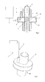
- the transmission means 8 may be rigid, semi-rigid or flexible (the choice is dictated by the need or not to shift the applicator 6 -and/or the emitter 4 as for example in Figure 8 - along the preform 7 during operation).
- the transmission means 8 can for example comprise a coaxial cable or a waveguide.
- a coaxial cable as exemplified in Figures 1-4
- advantageously a protruding portion of the central conductor, straight or curved is part of the emitter 4 for the excitation of the chamber 3.
- the excitation of the applicator 6 takes place through a coupling iris and a convenient transition in the waveguide, which constitute the emitter 4.
- the microwaves generation means 2 are variable and adjustable frequency microwave generation means (within the permitted ISM frequencies) for optimising energy efficiency, in particular for optimising the degree of absorption of the microwaves by the preform.
- the microwave generation means are also means of generating microwaves at a variable and conveniently adjustable power. In fact, the degree of absorption varies as parameters such as the geometry of the load or the temperature of the load vary.
- impedance matching is obtained through the controlled variation of the frequency emitted by the generation means 2.
- the impedance matching therefore envisages changing the frequency of the microwaves emitted by the generation means 2 so as to obtain resonance conditions at different frequencies.
- a resonance condition is sought to be found by varying the frequency of the microwaves so that the latter is equal or close to the actual frequency of the load (the load comprises the preform and potentially the applicator).
- the microwave generation means 2 comprise a "solid state generator” or more generally a generator that emits microwaves at a predetermined frequency that can be set by the user within permitted ranges (i.e. the "ISM frequencies" allocated for industrial, scientific and medical uses).
- the solid state generators in a predetermined operating configuration are able to emit microwaves all having a predetermined frequency value (and not a spectrum of frequencies centred around a nominal value).
- the solid state generators further allow both the power delivered and the on/off conditions to be varied extremely quickly in order to deliver power only when effectively necessary.
- the microwave generation means 2 generate microwaves having a precise frequency comprised between 2.4 and 2.5 GHz.
- the device 1 comprises gripping means for the preform, for example a gripper.
- the preform has an elongated development along a first imaginary straight line 71 integral with the preform itself.
- said gripper is suitable to grasp an end of the preform close to the neck of the preform.
- the device 1 further comprises shifting means of the gripping means of the preform relative to the applicator 6.
- the relative shifting means allow a relative shift of the applicator 6 and the gripping means along said first imaginary straight line 71 (as previously specified it is oriented along the elongation direction of the preform.
- a relative shift may be a translation or a roto-translation.
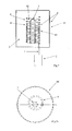
- the shell 44 identifies and surrounds the chamber 3.
- a chamber 3 is centrally symmetrical. This allows a distribution of the electric field according to a central symmetry.
- the microwaves are emitted by a surface of the emitter 4 that contributes to supplying the chamber 3.
- the shell 44 is a substantially cylindrical body with an axial cavity, said axial cavity being part of the chamber 3.
- the shell 44 is also centrally symmetrical.
- the shell 44 comprises at least one first opening 43 that puts the chamber 3 in communication with the outside and allows the insertion of the preform 7 into the chamber 3 and potentially the longitudinal motion relative to the applicator or of the emitter 4 with respect to the preform.
- the device 1 comprises two or more distinct transmission means 8 (for example coaxial cables) connecting an equal number of distinct emitters 4, to one or more distinct microwave generation means 2.
- the transmission means 8 are connected to the applicator 6 through emitters 4 situated at opposite points with respect to the preform housing chamber 3, (conveniently maintaining the central symmetry). This allows the power of the electromagnetic field to which the load is subject to be increased.
- the device 1 comprises a microwave reflector and/or concentration element 9.
- the element 9, in combination with the applicator 6 (in particular with the shell 44) and at least in one operating configuration defines an annular cavity 60 having one or more of the following characteristics:
- the element 9 in combination with the applicator 6 has the aim of concentrating the microwaves into said annular cavity 60.
- the intensity of the electromagnetic field is therefore higher in the annular cavity 60 in correspondence with the position of the preform.
- the element 9 comprises a portion that acts as a reflector and that is made of superficially conducting material; the element 9 comprises a portion that acts as a concentrator and that is made of low-loss dielectric material.
- the dielectric element 9 is used to disturb the distribution of the electromagnetic field in the applicator (in the chamber 3) so as to concentrate the electromagnetic field in the load positioning area.
- the element 9 is held in position through a low-loss dielectric support (PTFE, quartz, etc.).
- the combination of the applicator 6 and the element 9 allows the concentration of the microwaves in the annular cavity 60, that is, in the area in which the wall of the preform develops in thickness.
- the device 1 comprises relative shifting means of the preform-element 9 along the first straight line 71.
- the shift of the element 9 is integral with the shift of the applicator 6 (and/or the emitter 4).
- the element 9 in the operating configuration is introduced into a groove 70 defined inside the preform.
- the applicator 6 and the element 9 are coaxial.
- the element 9 (in particular a lateral wall facing a surface of the applicator delimiting the cavity 60) has a positive, negative or no curvature.
- the applicator 6 (or however the shell 44) is made of conducting material or insulating material covered with a conducting layer.
- the applicator 6 at two opposite ends of the applicator 6 there are two doors 45, 46 that allow the passage of at least one part of the preform. At least one of these doors 45, 46 is also useful for allowing the measurement of the temperature of the preform. The measurement of such temperature can conveniently be carried out indirectly based on the frequency emitted by the microwave generator 2 in the reflected power minimisation conditions. In fact, there is a biunivocal correspondence between the frequencies able to minimise the power reflected by the applicator 6 and the dielectric properties of the load at a determined temperature, and for a determined geometry of the load itself.
- the doors 45, 46 are shaped to prevent or minimise microwave leaks; in particular, they could comprise waveguides inserted in "cut-off” conditions or could be equipped with “chokes", which are well-known in the state of the art.
- the development of the emitter 4 along the first straight line 71 is determined by the spatial resolution that is desired for the thermal profiling of the preforms. Such resolution can be increased by varying the translation speed in the axial direction of the emitter with respect to the preform.
- the element 9 coaxial to the preform 7 could be integrated into the emitter 4. In such case, it is not necessarily used to concentrate the microwaves.
- the doors 45, 46 that allow the passage of the preform are afforded in two opposite ends of the containment shell 44.
- the shell 44 may also have larger dimensions than the preform, so that its presence does not excessively disturb the electromagnetic field in proximity to the emitter 4 and maintain the central symmetry of the electromagnetic field in proximity to the insertion area of the preform 7.
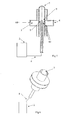
- the emitter 4 can be an elongated element and advantageously is intended to be inserted into the preform. Still as shown by way of example in Figures 5-6 , the emitter 4 preferably comprises/is constituted by the projecting internal conductor of a coaxial cable connected to the generation means 2. In that case, the emitter 4 is defined in technical jargon as an "antenna". The emitter 4 is also coaxial to the preform.
- the emitter 4 is shaped like a helical element 49 comprising one or more turns 41 which surround an area 42 housing the preform.
- the helical element 49 can have a variable pitch in order to perform differentiated heating in distinct portions of the preform located in the housing area 42 (see Figure 7 ). This embodiment is especially useful whenever the preform lies completely inside the area 42.
- the helical element 49 could have a substantially constant pitch (see Figure 8 ). Also in the embodiment of Figures 7-8 , the emitter 4 is conventionally defined as an antenna.
- the helical element 49 could also be positioned (at least partially, preferably completely) inside the preform.
- the centrally symmetrical chamber 3 has one or more section reducing areas in order to concentrate the electromagnetic field in correspondence with areas of the preform positioned close to such contractions.
- This section is evaluated orthogonally to the preponderant development direction of the preform in the chamber 3.
- the chamber 3 comprises an area with a reduced cross section interposed between two areas with an increased cross section.
- the excitement of the applicator 6 takes place through one or more emitters 4.
- the preform can be translated or roto-translated in the event of single section contractions, to reach the desired thermal profiling. In the event of multiple contractions, the preform can stay still or be simply rotated.
- This invention also relates to a method for heating a preform 7 in plastic material intended to become a container, such as a bottle.
- this method is implemented through a heating device 1 through microwaves having one or more of the characteristics previously described.
- the method comprises the steps of:
- preform 7 is subjected to stretch-blowing to allow the transformation into the final container.
- the microwave generating step and the microwave emitting step there is a step of transferring microwaves to the emitter 4 through transmission means 8 (as previously described with reference to the device 1).
- the emitter 4 could also be an introduction inlet for microwaves into the chamber 3, said inlet being an end of the transmission means 8.
- the method further comprises the step of varying the microwave generation frequency.
- the step of varying the frequency of the microwaves is advantageously performed during the heating of a same preform. In fact, the degree of absorption varies for example with the temperature of the preform 7. Therefore during the heating of the preform the microwave generation frequency varies.
- the microwave generation frequency is varied according to a preset profile (to be set by the user).
- the method further comprises a step for measuring the temperature of the preform 7; the step of varying the microwave generation frequency is controlled according to the feed-back from the step for measuring the temperature of the preform 7.
- step of positioning at least one part of the preform 7 inside the chamber 3 envisages that only a first tract of the part of the preform to be heated is introduced into the chamber 3 at first.
- the method comprises a step of shifting an applicator 6 (as defined with reference to the text relative to the device 1) with respect to the preform for submitting in succession various portions of the preform 7 to the microwaves coming from the emitter 4; this step can envisage the shift both of the applicator 6 and the preform 7 or the shift of the applicator 6 while keeping the preform 7 still or vice versa.
- the step of shifting the applicator 6 with respect to the preform can take place following a predefined law of motion; for example, such a shift can envisage alternate strokes along two opposite directions, each of said two strokes being able to envisage: an acceleration step, one or more constant speed steps and a deceleration step for performing the inversion of the motion.
- the step of shifting the applicator 6 with respect to the preform 7 can be controlled according to the feed-back from the step for measuring the temperature of the preform 7.
- the description that relates to the step of shifting the applicator 6 with respect to the preform 7 can be repeated for a step of shifting the emitter 4 with respect to the preform 7.
- the method envisages positioning at least one part of the preform 7 in a chamber 3 having a lateral surface integrated into the applicator 6.
- This envisages introducing the preform 7 through a first opening 43 in the chamber 3.
- the step of shifting the applicator 6 with respect to the preform 7 can comprise the step of making one part of the preform 7 already subjected to heating come out of the chamber 3, through a second opening 48.
- the second opening 48 and the first opening 43 are aligned (they are preferably coaxial) and are afforded in two opposite positions of the chamber 3.
- the method can envisage reflecting and concentrating the microwaves in correspondence with the thickness of the preform through a concentration and/or reflection element 9 preferably positioned in a groove 70 in the preform.
- the method further comprises the step of positioning a first element in a groove 70 in the preform 7 and a second annular element around the preform 7.
- a first element in a groove 70 in the preform 7 and a second annular element around the preform 7.
- Such second annular element identifies and surrounds the chamber 3 previously described.
- the first and the second annular element are an applicator 6 and a reflection and/or concentration element 9, which concentrates the microwaves into the thickness of the preform 7 interposed between at least one part of the applicator 6 and the element 9.
- the method comprises positioning the emitter 4 outside the preform and the element 9 inside another groove 70 defined by the preform.
- the step of shifting the applicator 6 with respect to the preform for submitting in succession various portions of the preform to the microwaves also envisages shifting the element 9 jointly with the applicator 6.
- the method comprises the step of positioning the emitter 4 inside the groove 70 in the preform 7.
- the method can envisage using such emitter 4 also as a reflection and/or concentration element 9 (the waves emitted by the emitter 4 are reflected by an annular element external to the preform and delimiting the chamber 3 and then return to the emitter 4 which acts as the reflection and/or concentration element).
- the method can further comprise the step for measuring the power reflected by the load (this is implemented in a known way by solid state generators).
- the step of generating the microwaves can be controlled according to the feed-back from the step for measuring the power reflected by the load.
- the method comprises the step of positioning the emitter 4, shaped like a helical element 49 comprising a plurality of turns, so that such turns surround the preform.
- the variable number of turns along the axis of the preform allows different heat generation to be obtained inside the preform (thermal profiling). In particular, this effect is obtained without the preform having to be subject to roto-translational motion with respect to the applicator 6.
- the step of positioning at least one part of a preform in the housing chamber 3 comprises the step of positioning such preform in a chamber 3 having one or more section variations along the development direction of the preform in order to concentrate the electromagnetic field in correspondence with areas of the preform positioned close to such section variations.
- the invention as it is conceived enables multiple advantages to be attained.
- the central symmetry of the electromagnetic field generated within the applicator 6 also makes it possible not to have to resort necessarily to load (preform) rotation systems, however maintaining a uniform temperature along the cross section of the load. In the event of a helical shaped variable pitch emitter, it will not even be necessary to have relative vertical translation between the applicator and the load, with a drastic simplification of the activations and a reduction in the number of components of the preform preheating system.
Landscapes
- Engineering & Computer Science (AREA)
- Manufacturing & Machinery (AREA)
- Mechanical Engineering (AREA)
- Physics & Mathematics (AREA)
- Thermal Sciences (AREA)
- Electromagnetism (AREA)
- Blow-Moulding Or Thermoforming Of Plastics Or The Like (AREA)
- Processing And Handling Of Plastics And Other Materials For Molding In General (AREA)
- Constitution Of High-Frequency Heating (AREA)
Applications Claiming Priority (1)
| Application Number | Priority Date | Filing Date | Title |
|---|---|---|---|
| IT000020A ITPR20120020A1 (it) | 2012-04-06 | 2012-04-06 | Dispositivo e metodo per il riscaldamento di una preforma in materiale plastico |
Publications (1)
| Publication Number | Publication Date |
|---|---|
| EP2647485A1 true EP2647485A1 (en) | 2013-10-09 |
Family
ID=46584130
Family Applications (1)
| Application Number | Title | Priority Date | Filing Date |
|---|---|---|---|
| EP13162571.7A Withdrawn EP2647485A1 (en) | 2012-04-06 | 2013-04-05 | Device and method for heating a preform in plastic material |
Country Status (2)
| Country | Link |
|---|---|
| EP (1) | EP2647485A1 (it) |
| IT (1) | ITPR20120020A1 (it) |
Cited By (5)
| Publication number | Priority date | Publication date | Assignee | Title |
|---|---|---|---|---|
| WO2016207546A1 (fr) | 2015-06-26 | 2016-12-29 | Sidel Participations | Procede de conditionnement thermique de preformes par micro-ondes avec detection de conformite des preformes |
| WO2017112585A1 (en) * | 2015-12-22 | 2017-06-29 | Mks Instruments, Inc. | Method and apparatus for processing dielectric materials using microwave energy |
| EP3313643B1 (fr) | 2015-06-26 | 2019-08-07 | Sidel Participations | Procede de chauffe hybride infrarouge et micro-ondes d'ebauches de recipients |
| JP2019202533A (ja) * | 2018-05-21 | 2019-11-28 | マイクロ波化学株式会社 | 成形装置、金型および成形品製造方法 |
| JP2020192817A (ja) * | 2018-05-21 | 2020-12-03 | マイクロ波化学株式会社 | 成形装置、金型および成形品製造方法 |
Citations (6)
| Publication number | Priority date | Publication date | Assignee | Title |
|---|---|---|---|---|
| GB1333450A (en) * | 1970-11-06 | 1973-10-10 | Raffinage Cie Francaise | Device for welding together sheets or strips of a material capable of absorbing ultra high-frequency waves |
| WO2006105769A1 (de) | 2005-04-07 | 2006-10-12 | Sig Technology Ltd. | Verfahren und vorrichtung zur temperierung von vorformlingen |
| WO2007131701A2 (de) * | 2006-05-11 | 2007-11-22 | Krones Ag | Mikrowellen-erwärmungsvorrichtung für kunststoffrohlinge und verfahren zum erwärmen von kunststoffrohlingen mit mikrowellen |
| EP2208597A2 (de) | 2009-01-16 | 2010-07-21 | Krones AG | Resonatoreinheit, Expansionsverfahren und Vorrichtung zur Erwärmung von Behältnissen |
| EP2281676A1 (de) * | 2009-07-31 | 2011-02-09 | Krones AG | Vorrichtung und Verfahren zum Umformen von Kunststoffvorformlingen mit synchroner Erwärmung und Reckung |
| EP2436507A2 (de) * | 2010-10-01 | 2012-04-04 | Krones AG | Vorrichtung und Verfahren zum Umformen von Kunstsoffvorformlingen zu Kunststoffbehältnissen mit variabler Ausstoßleistung |
-
2012
- 2012-04-06 IT IT000020A patent/ITPR20120020A1/it unknown
-
2013
- 2013-04-05 EP EP13162571.7A patent/EP2647485A1/en not_active Withdrawn
Patent Citations (6)
| Publication number | Priority date | Publication date | Assignee | Title |
|---|---|---|---|---|
| GB1333450A (en) * | 1970-11-06 | 1973-10-10 | Raffinage Cie Francaise | Device for welding together sheets or strips of a material capable of absorbing ultra high-frequency waves |
| WO2006105769A1 (de) | 2005-04-07 | 2006-10-12 | Sig Technology Ltd. | Verfahren und vorrichtung zur temperierung von vorformlingen |
| WO2007131701A2 (de) * | 2006-05-11 | 2007-11-22 | Krones Ag | Mikrowellen-erwärmungsvorrichtung für kunststoffrohlinge und verfahren zum erwärmen von kunststoffrohlingen mit mikrowellen |
| EP2208597A2 (de) | 2009-01-16 | 2010-07-21 | Krones AG | Resonatoreinheit, Expansionsverfahren und Vorrichtung zur Erwärmung von Behältnissen |
| EP2281676A1 (de) * | 2009-07-31 | 2011-02-09 | Krones AG | Vorrichtung und Verfahren zum Umformen von Kunststoffvorformlingen mit synchroner Erwärmung und Reckung |
| EP2436507A2 (de) * | 2010-10-01 | 2012-04-04 | Krones AG | Vorrichtung und Verfahren zum Umformen von Kunstsoffvorformlingen zu Kunststoffbehältnissen mit variabler Ausstoßleistung |
Cited By (11)
| Publication number | Priority date | Publication date | Assignee | Title |
|---|---|---|---|---|
| WO2016207546A1 (fr) | 2015-06-26 | 2016-12-29 | Sidel Participations | Procede de conditionnement thermique de preformes par micro-ondes avec detection de conformite des preformes |
| FR3037851A1 (fr) * | 2015-06-26 | 2016-12-30 | Sidel Participations | Procede de conditionnement thermique de preformes par micro-ondes avec detection de conformite des preformes |
| EP3313643B1 (fr) | 2015-06-26 | 2019-08-07 | Sidel Participations | Procede de chauffe hybride infrarouge et micro-ondes d'ebauches de recipients |
| WO2017112585A1 (en) * | 2015-12-22 | 2017-06-29 | Mks Instruments, Inc. | Method and apparatus for processing dielectric materials using microwave energy |
| KR20180096650A (ko) * | 2015-12-22 | 2018-08-29 | 엠케이에스 인스트루먼츠, 인코포레이티드 | 마이크로파 에너지를 사용하여 유전체 재료들을 프로세싱하기 위한 방법 및 장치 |
| US10071521B2 (en) | 2015-12-22 | 2018-09-11 | Mks Instruments, Inc. | Method and apparatus for processing dielectric materials using microwave energy |
| US10940635B2 (en) | 2015-12-22 | 2021-03-09 | Mks Instruments, Inc. | Method and apparatus for processing dielectric materials using microwave energy |
| KR102535795B1 (ko) | 2015-12-22 | 2023-05-22 | 엠케이에스 인스트루먼츠, 인코포레이티드 | 마이크로파 에너지를 사용하여 유전체 재료들을 프로세싱하기 위한 방법 및 장치 |
| JP2019202533A (ja) * | 2018-05-21 | 2019-11-28 | マイクロ波化学株式会社 | 成形装置、金型および成形品製造方法 |
| JP2020192817A (ja) * | 2018-05-21 | 2020-12-03 | マイクロ波化学株式会社 | 成形装置、金型および成形品製造方法 |
| JP7352965B2 (ja) | 2018-05-21 | 2023-09-29 | マイクロ波化学株式会社 | 成形装置、金型および成形品製造方法 |
Also Published As
| Publication number | Publication date |
|---|---|
| ITPR20120020A1 (it) | 2013-10-07 |
Similar Documents
| Publication | Publication Date | Title |
|---|---|---|
| EP2647485A1 (en) | Device and method for heating a preform in plastic material | |
| CN101454142B (zh) | 塑料坯加热装置 | |
| US9967925B2 (en) | RF oven with inverted F antenna | |
| US9018110B2 (en) | Apparatus and methods for microwave processing of semiconductor substrates | |
| EP1502489B1 (en) | Plasma generation and processing with multiple radiation sources | |
| HUP0204508A2 (en) | Microwave heating apparatus | |
| US8383999B2 (en) | Device for heating a sample by microwave radiation | |
| JP6812433B2 (ja) | マイクロ波エネルギーを用いて誘電体材料を処理するための方法及び装置 | |
| EP2395814A2 (en) | Microwave heating device | |
| KR20020013904A (ko) | 대면마이크로파처리 및 대면플라즈마생성을 위한직선연장형 장치 | |
| US20060237400A1 (en) | Surface cleaning and sterilization | |
| WO2019142578A1 (ja) | マイクロ波処理装置、および炭素繊維の製造方法 | |
| US8629379B2 (en) | Apparatus and method for heating plastic preforms | |
| JP2009100675A (ja) | 円偏波による食品の連続均一加熱装置 | |
| KR101636712B1 (ko) | 마이크로웨이브를 이용한 조리기기 | |
| EP2987388B1 (en) | A microwave emitting system | |
| EP2046093B1 (en) | Method and device for homogeneously heating materials by means of high-frequency electromagnetic radiation | |
| CN109417838A (zh) | 微波馈送系统 | |
| Lee et al. | Agricultural Process and Food Engineering; Design and Fabrication of a Dual Cylindrical Microwave and Ohmic Combination Heater for Processing of Particulate Foods | |
| KR20170073747A (ko) | 연료 처리 장치 | |
| JP2020098716A (ja) | マイクロ波処理装置、および炭素繊維の製造方法 | |
| KR20100024886A (ko) | 자외선 조사 장치 | |
| JP2004014831A5 (it) | ||
| DE60203314D1 (de) | Mikrowellen beheizte vorrichtung |
Legal Events
| Date | Code | Title | Description |
|---|---|---|---|
| PUAI | Public reference made under article 153(3) epc to a published international application that has entered the european phase |
Free format text: ORIGINAL CODE: 0009012 |
|
| AK | Designated contracting states |
Kind code of ref document: A1 Designated state(s): AL AT BE BG CH CY CZ DE DK EE ES FI FR GB GR HR HU IE IS IT LI LT LU LV MC MK MT NL NO PL PT RO RS SE SI SK SM TR |
|
| AX | Request for extension of the european patent |
Extension state: BA ME |
|
| 17P | Request for examination filed |
Effective date: 20140320 |
|
| RBV | Designated contracting states (corrected) |
Designated state(s): AL AT BE BG CH CY CZ DE DK EE ES FI FR GB GR HR HU IE IS IT LI LT LU LV MC MK MT NL NO PL PT RO RS SE SI SK SM TR |
|
| RIC1 | Information provided on ipc code assigned before grant |
Ipc: B29C 49/68 20060101ALN20160303BHEP Ipc: B29C 35/08 20060101ALN20160303BHEP Ipc: B29C 49/78 20060101ALI20160303BHEP Ipc: B29C 49/64 20060101AFI20160303BHEP Ipc: B29K 67/00 20060101ALI20160303BHEP |
|
| 17Q | First examination report despatched |
Effective date: 20160324 |
|
| STAA | Information on the status of an ep patent application or granted ep patent |
Free format text: STATUS: THE APPLICATION IS DEEMED TO BE WITHDRAWN |
|
| 18D | Application deemed to be withdrawn |
Effective date: 20181206 |