EP2647425B1 - Katalytischer reaktor mit einer härtungsvorrichtung, die mit einer tangentialen einspritzung einer härtungsflüssigkeit ausgestattet ist - Google Patents
Katalytischer reaktor mit einer härtungsvorrichtung, die mit einer tangentialen einspritzung einer härtungsflüssigkeit ausgestattet ist Download PDFInfo
- Publication number
- EP2647425B1 EP2647425B1 EP13305193.8A EP13305193A EP2647425B1 EP 2647425 B1 EP2647425 B1 EP 2647425B1 EP 13305193 A EP13305193 A EP 13305193A EP 2647425 B1 EP2647425 B1 EP 2647425B1
- Authority
- EP
- European Patent Office
- Prior art keywords
- nozzle
- fluid
- reactor
- enclosure
- range
- Prior art date
- Legal status (The legal status is an assumption and is not a legal conclusion. Google has not performed a legal analysis and makes no representation as to the accuracy of the status listed.)
- Active
Links
- 239000012530 fluid Substances 0.000 title claims description 63
- 238000010791 quenching Methods 0.000 title claims description 48
- 238000002347 injection Methods 0.000 title claims description 31
- 239000007924 injection Substances 0.000 title claims description 31
- 230000003197 catalytic effect Effects 0.000 title claims description 8
- 230000000171 quenching effect Effects 0.000 title description 26
- 239000007788 liquid Substances 0.000 claims description 27
- 239000011949 solid catalyst Substances 0.000 claims description 9
- 238000000034 method Methods 0.000 claims description 4
- 238000007599 discharging Methods 0.000 claims 1
- 239000007789 gas Substances 0.000 description 14
- 238000006243 chemical reaction Methods 0.000 description 12
- 238000002156 mixing Methods 0.000 description 7
- 229930195733 hydrocarbon Natural products 0.000 description 5
- 150000002430 hydrocarbons Chemical class 0.000 description 5
- 239000004215 Carbon black (E152) Substances 0.000 description 4
- UFHFLCQGNIYNRP-UHFFFAOYSA-N Hydrogen Chemical compound [H][H] UFHFLCQGNIYNRP-UHFFFAOYSA-N 0.000 description 3
- 229910052739 hydrogen Inorganic materials 0.000 description 3
- 239000001257 hydrogen Substances 0.000 description 3
- 239000007787 solid Substances 0.000 description 3
- XLYOFNOQVPJJNP-UHFFFAOYSA-N water Substances O XLYOFNOQVPJJNP-UHFFFAOYSA-N 0.000 description 3
- 239000003054 catalyst Substances 0.000 description 2
- 238000005984 hydrogenation reaction Methods 0.000 description 2
- 238000009434 installation Methods 0.000 description 2
- 239000011324 bead Substances 0.000 description 1
- 150000001722 carbon compounds Chemical class 0.000 description 1
- 238000004517 catalytic hydrocracking Methods 0.000 description 1
- 239000003153 chemical reaction reagent Substances 0.000 description 1
- 230000001143 conditioned effect Effects 0.000 description 1
- 230000000694 effects Effects 0.000 description 1
- 238000005516 engineering process Methods 0.000 description 1
- 230000005484 gravity Effects 0.000 description 1
- 238000000265 homogenisation Methods 0.000 description 1
- 150000002431 hydrogen Chemical class 0.000 description 1
- 239000000203 mixture Substances 0.000 description 1
- 239000003208 petroleum Substances 0.000 description 1
- 239000000376 reactant Substances 0.000 description 1
- 239000012429 reaction media Substances 0.000 description 1
- 238000007670 refining Methods 0.000 description 1
- 238000007634 remodeling Methods 0.000 description 1
- 239000000243 solution Substances 0.000 description 1
- 238000011144 upstream manufacturing Methods 0.000 description 1
Images


Classifications
-
- B—PERFORMING OPERATIONS; TRANSPORTING
- B01—PHYSICAL OR CHEMICAL PROCESSES OR APPARATUS IN GENERAL
- B01J—CHEMICAL OR PHYSICAL PROCESSES, e.g. CATALYSIS OR COLLOID CHEMISTRY; THEIR RELEVANT APPARATUS
- B01J8/00—Chemical or physical processes in general, conducted in the presence of fluids and solid particles; Apparatus for such processes
- B01J8/02—Chemical or physical processes in general, conducted in the presence of fluids and solid particles; Apparatus for such processes with stationary particles, e.g. in fixed beds
- B01J8/04—Chemical or physical processes in general, conducted in the presence of fluids and solid particles; Apparatus for such processes with stationary particles, e.g. in fixed beds the fluid passing successively through two or more beds
- B01J8/0496—Heating or cooling the reactor
-
- B—PERFORMING OPERATIONS; TRANSPORTING
- B01—PHYSICAL OR CHEMICAL PROCESSES OR APPARATUS IN GENERAL
- B01J—CHEMICAL OR PHYSICAL PROCESSES, e.g. CATALYSIS OR COLLOID CHEMISTRY; THEIR RELEVANT APPARATUS
- B01J8/00—Chemical or physical processes in general, conducted in the presence of fluids and solid particles; Apparatus for such processes
- B01J8/02—Chemical or physical processes in general, conducted in the presence of fluids and solid particles; Apparatus for such processes with stationary particles, e.g. in fixed beds
- B01J8/04—Chemical or physical processes in general, conducted in the presence of fluids and solid particles; Apparatus for such processes with stationary particles, e.g. in fixed beds the fluid passing successively through two or more beds
-
- B—PERFORMING OPERATIONS; TRANSPORTING
- B01—PHYSICAL OR CHEMICAL PROCESSES OR APPARATUS IN GENERAL
- B01J—CHEMICAL OR PHYSICAL PROCESSES, e.g. CATALYSIS OR COLLOID CHEMISTRY; THEIR RELEVANT APPARATUS
- B01J19/00—Chemical, physical or physico-chemical processes in general; Their relevant apparatus
- B01J19/26—Nozzle-type reactors, i.e. the distribution of the initial reactants within the reactor is effected by their introduction or injection through nozzles
-
- B—PERFORMING OPERATIONS; TRANSPORTING
- B01—PHYSICAL OR CHEMICAL PROCESSES OR APPARATUS IN GENERAL
- B01J—CHEMICAL OR PHYSICAL PROCESSES, e.g. CATALYSIS OR COLLOID CHEMISTRY; THEIR RELEVANT APPARATUS
- B01J37/00—Processes, in general, for preparing catalysts; Processes, in general, for activation of catalysts
-
- B—PERFORMING OPERATIONS; TRANSPORTING
- B01—PHYSICAL OR CHEMICAL PROCESSES OR APPARATUS IN GENERAL
- B01J—CHEMICAL OR PHYSICAL PROCESSES, e.g. CATALYSIS OR COLLOID CHEMISTRY; THEIR RELEVANT APPARATUS
- B01J8/00—Chemical or physical processes in general, conducted in the presence of fluids and solid particles; Apparatus for such processes
- B01J8/02—Chemical or physical processes in general, conducted in the presence of fluids and solid particles; Apparatus for such processes with stationary particles, e.g. in fixed beds
- B01J8/04—Chemical or physical processes in general, conducted in the presence of fluids and solid particles; Apparatus for such processes with stationary particles, e.g. in fixed beds the fluid passing successively through two or more beds
- B01J8/0446—Chemical or physical processes in general, conducted in the presence of fluids and solid particles; Apparatus for such processes with stationary particles, e.g. in fixed beds the fluid passing successively through two or more beds the flow within the beds being predominantly vertical
- B01J8/0449—Chemical or physical processes in general, conducted in the presence of fluids and solid particles; Apparatus for such processes with stationary particles, e.g. in fixed beds the fluid passing successively through two or more beds the flow within the beds being predominantly vertical in two or more cylindrical beds
- B01J8/0453—Chemical or physical processes in general, conducted in the presence of fluids and solid particles; Apparatus for such processes with stationary particles, e.g. in fixed beds the fluid passing successively through two or more beds the flow within the beds being predominantly vertical in two or more cylindrical beds the beds being superimposed one above the other
-
- B—PERFORMING OPERATIONS; TRANSPORTING
- B01—PHYSICAL OR CHEMICAL PROCESSES OR APPARATUS IN GENERAL
- B01J—CHEMICAL OR PHYSICAL PROCESSES, e.g. CATALYSIS OR COLLOID CHEMISTRY; THEIR RELEVANT APPARATUS
- B01J8/00—Chemical or physical processes in general, conducted in the presence of fluids and solid particles; Apparatus for such processes
- B01J8/02—Chemical or physical processes in general, conducted in the presence of fluids and solid particles; Apparatus for such processes with stationary particles, e.g. in fixed beds
- B01J8/04—Chemical or physical processes in general, conducted in the presence of fluids and solid particles; Apparatus for such processes with stationary particles, e.g. in fixed beds the fluid passing successively through two or more beds
- B01J8/0492—Feeding reactive fluids
-
- C—CHEMISTRY; METALLURGY
- C10—PETROLEUM, GAS OR COKE INDUSTRIES; TECHNICAL GASES CONTAINING CARBON MONOXIDE; FUELS; LUBRICANTS; PEAT
- C10G—CRACKING HYDROCARBON OILS; PRODUCTION OF LIQUID HYDROCARBON MIXTURES, e.g. BY DESTRUCTIVE HYDROGENATION, OLIGOMERISATION, POLYMERISATION; RECOVERY OF HYDROCARBON OILS FROM OIL-SHALE, OIL-SAND, OR GASES; REFINING MIXTURES MAINLY CONSISTING OF HYDROCARBONS; REFORMING OF NAPHTHA; MINERAL WAXES
- C10G49/00—Treatment of hydrocarbon oils, in the presence of hydrogen or hydrogen-generating compounds, not provided for in a single one of groups C10G45/02, C10G45/32, C10G45/44, C10G45/58 or C10G47/00
- C10G49/002—Apparatus for fixed bed hydrotreatment processes
-
- B—PERFORMING OPERATIONS; TRANSPORTING
- B01—PHYSICAL OR CHEMICAL PROCESSES OR APPARATUS IN GENERAL
- B01J—CHEMICAL OR PHYSICAL PROCESSES, e.g. CATALYSIS OR COLLOID CHEMISTRY; THEIR RELEVANT APPARATUS
- B01J2208/00—Processes carried out in the presence of solid particles; Reactors therefor
- B01J2208/00008—Controlling the process
- B01J2208/00017—Controlling the temperature
- B01J2208/00327—Controlling the temperature by direct heat exchange
- B01J2208/00336—Controlling the temperature by direct heat exchange adding a temperature modifying medium to the reactants
- B01J2208/00353—Non-cryogenic fluids
- B01J2208/00362—Liquid
-
- B—PERFORMING OPERATIONS; TRANSPORTING
- B01—PHYSICAL OR CHEMICAL PROCESSES OR APPARATUS IN GENERAL
- B01J—CHEMICAL OR PHYSICAL PROCESSES, e.g. CATALYSIS OR COLLOID CHEMISTRY; THEIR RELEVANT APPARATUS
- B01J2208/00—Processes carried out in the presence of solid particles; Reactors therefor
- B01J2208/00008—Controlling the process
- B01J2208/00017—Controlling the temperature
- B01J2208/00327—Controlling the temperature by direct heat exchange
- B01J2208/00336—Controlling the temperature by direct heat exchange adding a temperature modifying medium to the reactants
- B01J2208/00353—Non-cryogenic fluids
- B01J2208/00371—Non-cryogenic fluids gaseous
-
- B—PERFORMING OPERATIONS; TRANSPORTING
- B01—PHYSICAL OR CHEMICAL PROCESSES OR APPARATUS IN GENERAL
- B01J—CHEMICAL OR PHYSICAL PROCESSES, e.g. CATALYSIS OR COLLOID CHEMISTRY; THEIR RELEVANT APPARATUS
- B01J2208/00—Processes carried out in the presence of solid particles; Reactors therefor
- B01J2208/02—Processes carried out in the presence of solid particles; Reactors therefor with stationary particles
- B01J2208/023—Details
- B01J2208/024—Particulate material
- B01J2208/025—Two or more types of catalyst
-
- B—PERFORMING OPERATIONS; TRANSPORTING
- B01—PHYSICAL OR CHEMICAL PROCESSES OR APPARATUS IN GENERAL
- B01J—CHEMICAL OR PHYSICAL PROCESSES, e.g. CATALYSIS OR COLLOID CHEMISTRY; THEIR RELEVANT APPARATUS
- B01J2219/00—Chemical, physical or physico-chemical processes in general; Their relevant apparatus
- B01J2219/00002—Chemical plants
- B01J2219/00018—Construction aspects
- B01J2219/00024—Revamping, retrofitting or modernisation of existing plants
Definitions
- the present invention relates to the field of fixed bed type catalytic reactors, which are in particular implemented in the hydrotreatment operations of hydrocarbon feeds.
- the invention describes a system for injecting a quenching fluid into the reactor.
- Catalytic reactors are used in particular in the petroleum and petrochemical industry to treat hydrocarbon effluents by hydrotreatment reaction. These reactions cause the carbon compounds to react with hydrogen in hydrogenation, hydrodesulfurization, hydrogenation, hydrocracking and hydrodearomatization reactions.
- a catalytic reactor is generally composed of a chamber of cylindrical shape, comprising one or more catalytic beds, ie a bed of solids, for example in the form of extruded or sphere, whose role is to catalyze the hydrotreatment reaction.
- the reactor is fed at the top with a reaction fluid composed of the hydrocarbon effluent and hydrogen.
- the exothermic nature of the hydrotreatment reactions carried out in refining and in petrochemistry necessitates dividing the solid catalyst volume into several beds and performing cold fluid injections to cool the reaction medium and to supply the reactor with reagents.
- the injected fluid may be liquid, usually a hydrocarbon cut, or a gas, for example hydrogen, depending on the applications.
- the cold fluid is introduced into the reactor at a device called quench box, also commonly called “quench” box.
- quench box also commonly called “quench” box.
- the main purpose of the "quench” box technology is to mix the hot fluids from the upper bed with the cold injected fluid. Once the fluids are mixed, they are redistributed on the reactor section by a distribution device, before entering the catalytic bed located under the distributor plate.
- the documents US 5403560 and US 2010/0303685 propose to implement a rotational flow of the fluid on the collection tray, upstream of the passage in the quench box.
- the rotary flow is generated in these examples by a particular geometry of the collecting trays, for example by means of spiral-shaped elements positioned to force the flow to rotate on the collection tray before entering the quench box. Nevertheless, the positioning of inserts or spiral baffles is bulky and bulky in the reactor.
- the document US 2004/0234434 has a quenching device in which a rotational flow is generated on the collection tray.
- the flow is generated by the injection of the cold fluid by means of a toroidal circular injection rod having a plurality of outlet pipes.
- the jets of cold fluid are directed outwardly with respect to the axis of the reactor so as to induce a rotary flow.
- the injection cane is bulky and mechanically difficult to install and maintain in a reactor.
- the document US 2011/0123410 describes a quenching device in which a rotary flow is generated downstream of the quench box.
- the outlet of the quench box is positioned above a perforated plate so as to generate a rotary flow.
- the objective of the present invention is to improve the mixing of the quenching fluid with the hot fluids by positioning the injection nozzle of the fluid at the periphery of the reactor at the collector plate so as to generate a rotational flow on the tray.
- the present invention proposes to use a bent injection nozzle, opening above the collecting tray near the reactor enclosure and producing a jet whose direction is substantially tangential to the reactor enclosure in order to produce simple and effective rotational movement of the fluid on the collection tray.
- the present invention describes a catalytic reactor according to claim 1.
- the nozzle may open into the wall of the enclosure so as to inject a fluid in a direction forming an angle between -10 ° and + 10 ° relative to the horizontal direction .
- the end of the injection nozzle may be composed of a straight tubular portion forming an angle of between -10 ° and + 10 ° with respect to the direction tangent to the wall of the enclosure at the orifice of the nozzle.
- the straight tubular portion may form an angle between -10 ° and + 10 ° with respect to the horizontal direction.
- the nozzle can form a tube of length between 5 cm and 50 cm, measured in the collection space.
- the nozzle may be disposed at a distance of less than 30 cm from the enclosure and at a distance of less than 20 cm from the collection tray.
- the reactor may comprise a gas and liquid distributor plate disposed under the quench box.
- the reactor may comprise a perforated plate disposed between the quench box and the distributor plate.
- the invention also describes the use of a reactor according to the invention, in which it is possible to inject via said nozzle a fluid comprising at least 70% by volume of liquid.
- fluid can be injected through said nozzle at a speed of between 1 and 15 m / s.
- the invention also describes a method according to claim 11 for obtaining a reactor according to one of claims 1 to 8.
- the device according to the invention achieves excellent mixing performance as illustrated below in the examples.
- the injection cane according to the invention is of reduced size compared to similar solutions, particularly with respect to the device described by the document US 2004/0234434 .
- the mechanical assembly of the injection rod on the tray is easy, moderate cost.
- the height of the collection space above the collection tray can therefore be reduced. Therefore, for the same internal reactor volume, the implementation of the present invention allows a volume gain of solid catalyst.
- the present invention can be implemented in existing installations.
- the present invention can advantageously replace a quenching device with a straight injection pipe, in order to improve quenching performance.
- by changing the position of the grid supporting the bed of solid catalyst it is possible to reduce the collection space and thus to gain volume that can be used to carry out the reaction.
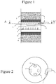
- the figure 1 represents a reactor portion, in which a hydrotreatment reaction is carried out.
- the reactor is composed of an enclosure 1 containing at least one bed of solid catalyst 2.
- the enclosure 1 may have the shape of a closed cylinder at its ends.
- the axis of the cylinder is oriented in the vertical direction.
- the cylinder may have a diameter of between 1 and 10 meters and a height of between 3 and 20 meters.
- the reactor is fed at the top with a reaction fluid, composed of a gas and a liquid, for example a charge of liquid hydrocarbons and hydrogen gas.
- the reaction fluid flows in a downward vertical direction in the chamber 1, in particular under the effect of gravity. In other words, the gas and the liquid flow co-current from top to bottom in the reactor.
- a solid catalyst which may be in the form of extrudates or beads arranged between two grids to form a bed that extends in general on a whole horizontal section of the interior volume of the enclosure. Due to the exothermic reaction, the volume of solid catalyst is divided into several beds. On the figure 1 two beds 2 and 11 of solid catalysts are shown.
- the bed 2 of solid catalyst is placed on a layer 3 of inert solid grains, commonly called "grading".
- Layer 3 is supported by a grid.
- An empty space 4 is located between the grid supporting the layer 3 and the collection tray 6.
- the gas and the liquid flowing through the bed 2 open into the empty space 4 hereinafter called the collection space.
- the collection tray 6 collects the liquid and the gas arriving in the collection space 4.
- the collection tray is the first mechanical member encountered by the liquid and the gas flowing in the collection space 4.
- the collection tray is a horizontal disk that covers the internal section of the enclosure 1.
- an injection rod 5 also called an injection nozzle, makes it possible to introduce a cold fluid from outside the reactor into the collection space 4.
- the cane 5 is composed of a portion of 4.
- the pipe has a single outlet in the space 4, this orifice being located at the end of the pipe.
- the figure 2 represents a view of the reactor of the figure 1 according to AA 'section.
- the shape and, possibly, the dimensions, of the pipe forming the rod 5 are chosen so that the direction of the jet of fluid at the outlet of the rod is directed in a substantially horizontal direction and substantially tangential to the wall of the pregnant 1.
- the Figures 2A and 2B represent two forms of shaped rod 5 according to the invention.
- the end of the rod is in the form of a tube, for example a straight tube that is to say that extends in a straight direction.
- the rod may be in the shape of a cylinder of circular section or of the shape of a truncated cone.
- the end of the rod 5 may be a cylinder of circular section of diameter D.
- the rod 5 may be tube-shaped whose axis is curved.
- cane 5 is a tube of circular section of constant diameter D, the axis 16 of the tube forming an arc concentric to the circle described by the chamber 1 in a horizontal plane.
- the rod 5 is dimensioned to direct the cold fluid in a direction substantially tangential to the wall of the enclosure 1.
- Figures 2A and 2B the end of the rod 5 is formed by a portion of tube which extends along the straight line 14.
- the direction tangential to the wall of the chamber 1 at the outlet orifice of the rod 5 is represented by the straight line 15.
- the direction of the jet of the fluid issuing from the rod is substantially tangential to the internal surface of the wall of the enclosure 1 at the outlet, that is to say that the direction of the jet forms an angle ⁇ between -10 ° and + 10 °, preferably between -5 ° and + 5 °, relative to the tangent to the inner surface of the enclosure 1 at the outlet of the cane 5, that is to say with respect to the line 15.
- the rod 5 is dimensioned to direct the cold fluid in a substantially horizontal direction.
- the direction of the jet of fluid from the rod that is to say the direction in which extends the tube forming the end of the rod at the outlet may be substantially horizontal.
- the direction of the jet forms an angle of between -10 ° and +10, preferably between -5 ° and + 5 °, with respect to a horizontal direction.
- the rod is positioned near the wall of the chamber 1 and near the collecting plate 6.
- the maximum spacing between the wall of the chamber 1 and the rod is between 0 and 40 cm, preferably between 0 and 30 cm.
- the maximum spacing between the surface of the collection tray and the cane is between 0 and 10 cm.
- the length of the cane 5 in the collection space 4 is reduced, for example between 5 and 50 cm, preferably between 5 and 20 cm.
- the orifice located at the end of the nozzle may open at a distance of less than 40 cm, preferably less than 30 cm from the chamber 1.
- the orifice may open at a distance of less than 10 cm. the collection tray.
- the collection plate 6 communicates with a quench box 7 which has the function of mixing the liquid and the gas collected on the plate 6.
- the box 7 may have various geometries.
- the quenching box comprises two inlet orifices 12 communicating with the collection space 4 through the plate 6.
- the fluids collected on the plate 6 flow into the quench box 7 via the orifices 12.
- gaseous and liquid fluids are mixed in the box 7 which may have different internal configurations.
- the mixing box 7 can be produced according to the teaching of the document FR 2824495 .
- the quench box 7 has two outlet orifices 13 communicating with the space below the box 7.
- the orifices 13 are located on the bottom of the box 7, in staggered inlet orifices 12.
- a fluid is injected comprising at least 70%, see 80% by volume of liquid, so that the inertia of the injected liquid generates a better rotational movement of the fluid on the plate 6.
- the cold fluid can be injected by the rod 5 at a speed preferably between 1 and 15 m / s.
- the shape and the dimensions can be adapted according to the pressure at which the cold fluid is available to inject the fluid at a speed of between 1 and 15 ms into the collection space 4.
- the quench box 7 is a distributor plate 9.
- the document US 6,093,373 describes an embodiment of a distributor plate.
- the plate 9 makes it possible to dispense the fluids coming from the box 7 onto the catalyst bed 11.
- the plate 9 is provided with distribution elements, for example chimneys, for distributing the gas and the liquid over the entire surface of the section. of the reactor.
- the plate 8 is composed a perforated plate.
- a layer 10 of inert solid grains, commonly called “grading” can be placed above the bed 11.
- the effectiveness of the system according to the proposed invention is compared to that of a straight rod device described by the figure 3 and to that of a circular cane device described by the figure 4 .
- the figure 3 has a straight rod quenching device similar to that disclosed in the document US 7,314,602 .
- the references of the figure 3 identical to those of the figure 1 designate the same elements.
- the injection rod 5A is a perforated straight tube, which distributes the cold fluid to different locations on the collection tray 6.
- the figure 4 has a quenching device with a circular injection rod 5B, similar to that disclosed by the document US 2004/0234434 .
- a cold model was used to compare the mixing performance between three different quench configurations according to the figure 2 , according to figure 3 and according to the figure 4 .
- the model is composed of a straight cylinder in a vertical position, whose section is 0.48 m in diameter.
- the model has a catalyst bed of 1 m height.
- the empty space 4 where the fluid collection is carried out, above the collection tray 6, has a height of 20 cm.
- the cylinder is fed at the top with a mixture of water and air at 1 bar at 50 ° C. Tests are performed at different surface velocities of gas (Vsg) and liquid (Vsl) at the upper bed entrance.
- the cold quenching fluid is either liquid (water) or gas (air). It is injected with a flow equal to half the flow of the same phase entering the upper bed.
- the quenching fluid is gaseous.
- the superficial velocity of liquid (Vs1) entering the upper bed is greater than 1 cm / s, the quenching fluid is liquid.
- the tests performed at 0.002 m / s, 0.005 m / s and 0.008 m / s are performed with injection of a gas (air) and the tests performed at 0.015 m / s and 0.02 m / s are made with injection of a liquid (water).
- the quench box is identical to the box 7 schematized by the Figures 1 and 2 .
- the orifices 12 and 13 are circular with a diameter of 3 cm.
- the injection rod is a bent tube, with a diameter D equal to 2 cm, bonded to the wall of the column and the collection tray.
- the end of the rod 5 is a straight cylinder whose axis is oriented perfectly tangential to the cylindrical wall of the model.
- the cane 5A is a straight cylinder 3 cm in internal diameter, comprising 6 holes of 1 cm in diameter.
- the cane 5B is circular forms a torus 20 cm in diameter, and 3 cm of internal diameter.
- the torus is equipped with seven exit holes, 1 cm in diameter, oriented at 45 ° to the tangential direction.
- thermocouples For each configuration tested, six thermocouples are positioned at the lower bed entrance and in the "grading" layer. The maximum temperature difference measured by these thermocouples defines the residual temperature difference, noted ⁇ T used to compare the configurations.
- the configuration 1 according to the invention gives better results than the rods according to the configurations 2 and 3, while being lighter, mechanical mounting easier, and less cumbersome.
- the benefits of the device according to the invention are therefore very important.
Landscapes
- Chemical & Material Sciences (AREA)
- Organic Chemistry (AREA)
- Chemical Kinetics & Catalysis (AREA)
- Engineering & Computer Science (AREA)
- Oil, Petroleum & Natural Gas (AREA)
- Materials Engineering (AREA)
- General Chemical & Material Sciences (AREA)
- Devices And Processes Conducted In The Presence Of Fluids And Solid Particles (AREA)
- Physical Or Chemical Processes And Apparatus (AREA)
- Production Of Liquid Hydrocarbon Mixture For Refining Petroleum (AREA)
Claims (11)
- Katalytischer Reaktor, umfassend einen Raum (1), der mindestens zwei feste Katalysatorbetten (2; 11) einschließt, die durch eine Zwischenzone getrennt sind, umfassend eine Sammelplatte (6), die mit einer Härtekammer (7) zusammenwirkt, die unter der Sammelplatte (6) angeordnet ist, wobei der Reaktor eine Einspritzdüse (5) eines Härtefluids umfasst, dadurch gekennzeichnet, dass die Einspritzdüse (5) in einem Sammelraum (4) angeordnet ist, der sich in der Zwischenzone über der Sammelplatte (6) und an der Peripherie des Reaktors befindet, dass die Einspritzdüse (5) in einem gebogenen Rohr besteht, umfassend eine einzige Öffnung, die in den Sammelraum mündet, wobei sich die Öffnung am Ende des Rohrs befindet, dass der maximale Abstand zwischen dem Raum (1) und der Einspritzdüse (5) zwischen 0 und 40 cm beträgt, und dass das Ende der Einspritzdüse (5) einen röhrenförmigen Abschnitt umfasst, der derart ausgeführt ist, dass das Härtefluid in den Sammelraum (4) in einer im Wesentlichen horizontalen Richtung eingespritzt wird, wobei ein Winkel zwischen -10° und +10° in Bezug zur Tangentialrichtung an die Innenfläche der Wand des Raums (1) im Bereich des Ausgangs des röhrenförmigen Abschnitts gebildet wird, um eine Drehbewegung des Fluids auf der Sammelplatte (6) zu erzeugen.
- Reaktor nach Anspruch 1, dadurch gekennzeichnet, dass die Düse (5) an der Wand des Raums (1) mündet, um ein Fluid in eine Richtung einzuspritzen, die einen Winkel zwischen - 10° und +10° in Bezug zur Horizontalrichtung bildet.
- Reaktor nach einem der Ansprüche 1 und 2, dadurch gekennzeichnet, dass die Einspritzdüse (5) aus einem geraden röhrenförmigen Abschnitt besteht, der einen Winkel (θ) zwischen -10° und +10° in Bezug zur Tangentialrichtung an die Wand des Raums (1) im Bereich der Öffnung der Düse bildet.
- Reaktor nach Anspruch 3, dadurch gekennzeichnet, dass der gerade röhrenförmige Abschnitt einen Winkel zwischen -10° und +10° in Bezug zur Horizontalrichtung bildet.
- Reaktor nach einem der vorhergehenden Ansprüche, dadurch gekennzeichnet, dass die Düse (5) ein Rohr mit einer Länge zwischen 5 cm und 50 cm, gemessen im Sammelraum (4), bildet.
- Reaktor nach einem der vorhergehenden Ansprüche, dadurch gekennzeichnet, dass die Düse (5) in einem Abstand unter 30 cm zum Raum (1) und in einem Abstand unter 20 cm zur Sammelplatte (6) angeordnet ist.
- Reaktor nach einem der vorhergehenden Ansprüche, umfassend eine Platte (9) zur Verteilung von Gas und Flüssigkeit, die unter der Härtekammer (7) angeordnet ist.
- Reaktor nach Anspruch 7, umfassend eine perforierte Platte (8), die zwischen der Härtekammer (7) und der Verteilungsplatte (9) angeordnet ist.
- Verfahren für den Einsatz eines Reaktors nach einem der Ansprüche 1 bis 8, dadurch gekennzeichnet, dass durch die Düse (5) ein Fluid, umfassend mindestens 70 % Volumen Flüssigkeit, eingespritzt wird.
- Verfahren nach Anspruch 9, bei dem durch die Düse (5) ein Fluid mit einer Geschwindigkeit zwischen 1 und 15 m/s eingespritzt wird.
- Verfahren, um einen Reaktor nach einem der Ansprüche 1 bis 8 zu erhalten, bei dem eine Neumodellierung eines bestehenden Reaktors erfolgt, wobei die alte Düse durch eine Einspritzdüse (5) ersetzt wird, deren Ende einen röhrenförmigen Abschnitt umfasst, der derart ausgeführt ist, dass das Fluid in den Sammelraum in einer im Wesentlichen horizontalen Richtung eingespritzt wird, wobei ein Winkel zwischen -10° und +10° in Bezug zur Tangentialrichtung an die Wand des Raums im Bereich des röhrenförmigen Abschnitts gebildet wird.
Priority Applications (1)
| Application Number | Priority Date | Filing Date | Title |
|---|---|---|---|
| HRP20171967TT HRP20171967T1 (hr) | 2012-04-04 | 2017-12-19 | Katalitički reaktor s ureðajem za gašenje predviðenim s tangencijalnim injektiranjem fluida za gašenje |
Applications Claiming Priority (1)
| Application Number | Priority Date | Filing Date | Title |
|---|---|---|---|
| FR1201009A FR2989006B1 (fr) | 2012-04-04 | 2012-04-04 | Reacteur catalytique avec dispositif de trempe muni d'une injection tangentielle d'un fluide de trempe |
Publications (2)
| Publication Number | Publication Date |
|---|---|
| EP2647425A1 EP2647425A1 (de) | 2013-10-09 |
| EP2647425B1 true EP2647425B1 (de) | 2017-10-04 |
Family
ID=47748555
Family Applications (1)
| Application Number | Title | Priority Date | Filing Date |
|---|---|---|---|
| EP13305193.8A Active EP2647425B1 (de) | 2012-04-04 | 2013-02-21 | Katalytischer reaktor mit einer härtungsvorrichtung, die mit einer tangentialen einspritzung einer härtungsflüssigkeit ausgestattet ist |
Country Status (10)
| Country | Link |
|---|---|
| EP (1) | EP2647425B1 (de) |
| JP (1) | JP6173744B2 (de) |
| KR (1) | KR102002651B1 (de) |
| CN (1) | CN103357356B (de) |
| ES (1) | ES2650082T3 (de) |
| FR (1) | FR2989006B1 (de) |
| HR (1) | HRP20171967T1 (de) |
| PT (1) | PT2647425T (de) |
| RU (1) | RU2627389C2 (de) |
| SG (2) | SG193774A1 (de) |
Families Citing this family (6)
| Publication number | Priority date | Publication date | Assignee | Title |
|---|---|---|---|---|
| ES2580531T3 (es) | 2014-06-11 | 2016-08-24 | Neste Oyj | Método y aparato para mezclar fluidos |
| FR3034324B1 (fr) | 2015-04-01 | 2017-03-17 | Ifp Energies Now | Dispositf de melange et de distribution comprenant un plateau de distribution avec ouvertures peripheriques |
| FR3034325B1 (fr) * | 2015-04-01 | 2017-03-17 | Ifp Energies Now | Dispositf compact de melange et de distribution combine |
| RU2674950C1 (ru) * | 2018-04-09 | 2018-12-13 | Игорь Анатольевич Мнушкин | Каталитический реактор |
| US10589244B1 (en) * | 2019-02-07 | 2020-03-17 | Uop Llc | Hydroprocessing reactor internals having reduced height |
| US11298670B2 (en) * | 2020-04-24 | 2022-04-12 | Uop Llc | Compact quench zone reactor internals |
Family Cites Families (21)
| Publication number | Priority date | Publication date | Assignee | Title |
|---|---|---|---|---|
| US3592612A (en) * | 1966-11-02 | 1971-07-13 | John H Ballard | Two-stage apparatus for mixing fluids in concurrent downflow relationship |
| JPS62194432U (de) * | 1986-05-30 | 1987-12-10 | ||
| US5403560A (en) | 1993-05-13 | 1995-04-04 | Texaco Inc. | Fluids mixing and distributing apparatus |
| DK171572B1 (da) * | 1994-01-12 | 1997-01-20 | Topsoe Haldor As | Fremgangsmåde og indretning til blanding af gasser |
| AU689553B2 (en) * | 1994-03-01 | 1998-04-02 | Methanol Casale S.A. | Mixing assembly for gaseous flows at different temperatures,in particular for heterogeneous exothermic synthesis reactors |
| FR2745202B1 (fr) | 1996-02-27 | 1998-04-30 | Inst Francais Du Petrole | Plateau pour distribuer un melange polyphasique a travers un lit catalytique |
| US6098965A (en) | 1996-06-04 | 2000-08-08 | Fluor Corporation | Reactor distribution apparatus and quench zone mixing apparatus |
| US5837208A (en) | 1996-06-12 | 1998-11-17 | Uop | Hydroprocessing reactor mixer/distributor |
| US5935413A (en) | 1997-12-03 | 1999-08-10 | Mobil Oil Corporation | Interbed gas-liquid mixing system for cocurrent downflow reactors |
| US6183702B1 (en) * | 1998-12-21 | 2001-02-06 | Chevron U.S.A. Inc. | Fluid distributor assembly for a multi-bed, downflow catalytic reactor |
| EP1341875B1 (de) | 2000-12-11 | 2004-08-11 | Shell Internationale Researchmaatschappij B.V. | Von oben nach unten durchströmter mehrbett-reaktor |
| FR2824495B1 (fr) * | 2001-05-09 | 2005-03-04 | Inst Francais Du Petrole | Enceinte reactionnelle de forme allongee le long d'un axe contenant au moins un lit de catalyseur solide et au moins une boite de contact, de melange et de trempe |
| FR2826594B1 (fr) * | 2001-07-02 | 2003-09-26 | Inst Francais Du Petrole | Boite de contact, de melange et de trempe de fluides comportant au moins une sortie annulaire peripherique et enceinte reactionnelle de forme allongee le long d'un axe comprenant ladite boite |
| EA007052B1 (ru) * | 2002-11-08 | 2006-06-30 | МОРТЕН МЮЛЛЕР ЛТД., АпС | Смесительное устройство для двухфазного потока в каталитическом реакторе |
| US7074372B2 (en) * | 2003-05-16 | 2006-07-11 | Exxonmobil Research And Engineering Company | Multiphase mixing device with improved quench injection for inducing rotational flow |
| US20070248510A1 (en) * | 2006-04-25 | 2007-10-25 | Dean Anne M | Dual gas-liquid spargers for catalytic processing units |
| JP5412054B2 (ja) * | 2008-05-02 | 2014-02-12 | 株式会社ワコール | 衣料用経編地及びその製造方法並びに衣料用経編地の編構造 |
| US8181942B2 (en) * | 2008-06-26 | 2012-05-22 | Uop Llc | Liquid redistribution device for multibed reactors |
| US8017095B2 (en) | 2009-05-29 | 2011-09-13 | Chevron U.S.A. Inc. | Mixing device for a down-flow reactor |
| FR2952835B1 (fr) * | 2009-11-20 | 2011-12-09 | Inst Francais Du Petrole | Dispositif compact de melange de fluides dans un reacteur a ecoulement descendant |
| US8673246B2 (en) * | 2011-03-23 | 2014-03-18 | Uop Llc | Process for contacting one or more fluids and a reactor relating thereto |
-
2012
- 2012-04-04 FR FR1201009A patent/FR2989006B1/fr active Active
-
2013
- 2013-02-21 EP EP13305193.8A patent/EP2647425B1/de active Active
- 2013-02-21 ES ES13305193.8T patent/ES2650082T3/es active Active
- 2013-02-21 PT PT133051938T patent/PT2647425T/pt unknown
- 2013-04-02 JP JP2013076508A patent/JP6173744B2/ja active Active
- 2013-04-03 RU RU2013114974A patent/RU2627389C2/ru active
- 2013-04-03 SG SG2013025101A patent/SG193774A1/en unknown
- 2013-04-03 CN CN201310115316.0A patent/CN103357356B/zh active Active
- 2013-04-03 SG SG10201505175UA patent/SG10201505175UA/en unknown
- 2013-04-04 KR KR1020130037059A patent/KR102002651B1/ko active IP Right Grant
-
2017
- 2017-12-19 HR HRP20171967TT patent/HRP20171967T1/hr unknown
Non-Patent Citations (1)
| Title |
|---|
| None * |
Also Published As
| Publication number | Publication date |
|---|---|
| CN103357356A (zh) | 2013-10-23 |
| JP2013223862A (ja) | 2013-10-31 |
| KR102002651B1 (ko) | 2019-07-23 |
| CN103357356B (zh) | 2018-01-23 |
| JP6173744B2 (ja) | 2017-08-02 |
| SG193774A1 (en) | 2013-10-30 |
| HRP20171967T1 (hr) | 2018-02-09 |
| EP2647425A1 (de) | 2013-10-09 |
| KR20130112807A (ko) | 2013-10-14 |
| FR2989006A1 (fr) | 2013-10-11 |
| FR2989006B1 (fr) | 2016-11-18 |
| PT2647425T (pt) | 2017-12-01 |
| RU2627389C2 (ru) | 2017-08-08 |
| RU2013114974A (ru) | 2014-10-10 |
| SG10201505175UA (en) | 2015-08-28 |
| ES2650082T3 (es) | 2018-01-16 |
Similar Documents
| Publication | Publication Date | Title |
|---|---|---|
| EP2647425B1 (de) | Katalytischer reaktor mit einer härtungsvorrichtung, die mit einer tangentialen einspritzung einer härtungsflüssigkeit ausgestattet ist | |
| EP2773450B1 (de) | Verteilerplatte für eine gas/flüssigkeitsmischung mit weitgehend gegen mangelnde horizontalität unempfindlichen verteilerelementen | |
| EP1866068B1 (de) | Vorrichtung zum mischen und verteilen eines gases und einer flüssigkeit vor einer granulatschüttung | |
| EP2151277B1 (de) | Gleichstrom aufsteigend Gas-Flüssigkeit Reaktor mit Verteilerplate | |
| CA2925656A1 (fr) | Dispositif de melange et de distribution avec zones de melange et d'echange | |
| FR3051375A1 (fr) | Dispositif de filtration et de distribution pour reacteur catalytique. | |
| EP3374073A1 (de) | Filterungs- und verteilungsvorrichtung für einen katalytischen reaktor | |
| EP0107986A1 (de) | Verfahren und Vorrichtung zur Wasserstoffumwandlung von Kohlenwasserstoffen | |
| EP3495037B1 (de) | System zur verteilung einer flüssigen und/oder gasförmigen phase in einer reaktionskammer | |
| FR3006607A1 (fr) | Dispositif de distribution d'un fluide | |
| WO2016155938A1 (fr) | Dispositif compact de melange et de distribution combine de fluides pour un reacteur catalytique | |
| EP3618947B1 (de) | Neue vorrichtung zum verteilen eines polyphasengemisches in einer kammer mit einem fluidisierten medium | |
| FR2993794A1 (fr) | Reacteur de regeneration en continu de catalyseur avec caisson de melange de gaz et de distribution de gaz dans la zone d'oxychloration | |
| EP2162207B1 (de) | Gehäuse mit einer granularen schicht und mit verteilung einer gasphase und einer flüssigphase, die entsprechend einem ansteigenden fluss in besagtem gehäuse fliessen | |
| EP2760575B1 (de) | Reaktor mit einem verteilungsschale zur verteilung einer mehrphasigen mischung mit geneigten peripheren leitungen | |
| FR3043339A1 (fr) | Dispositif de filtration et de distribution pour reacteur catalytique | |
| FR2818559A1 (fr) | Dispositif permettant de realiser une injection separee et une distribution homogene de deux fluides | |
| EP1646444B1 (de) | Ventilplatte zum verteilen einer gasförmigen phase und einer flüssigen phase | |
| FR2980719A1 (fr) | Plateau distributeur pour la distribution d'un melange polyphasique avec cheminees tronquees en peripherie. | |
| EP3536398A1 (de) | Vorrichtung zur mischung eines fluides für einen katalytischen bett | |
| FR3066411B1 (fr) | Dispositif de melange et de distribution avec systeme d'equilibrage des fluides | |
| FR3072306A1 (fr) | Dispositif de melange et de distribution avec ouverture longitudinale | |
| FR3083993A1 (fr) | Dispositif de melange et de distribution avec buse d'injection perfectionnee | |
| FR2889972A1 (fr) | Reacteur chimique a volume catalytique reduit |
Legal Events
| Date | Code | Title | Description |
|---|---|---|---|
| PUAI | Public reference made under article 153(3) epc to a published international application that has entered the european phase |
Free format text: ORIGINAL CODE: 0009012 |
|
| AK | Designated contracting states |
Kind code of ref document: A1 Designated state(s): AL AT BE BG CH CY CZ DE DK EE ES FI FR GB GR HR HU IE IS IT LI LT LU LV MC MK MT NL NO PL PT RO RS SE SI SK SM TR |
|
| AX | Request for extension of the european patent |
Extension state: BA ME |
|
| 17P | Request for examination filed |
Effective date: 20140409 |
|
| RBV | Designated contracting states (corrected) |
Designated state(s): AL AT BE BG CH CY CZ DE DK EE ES FI FR GB GR HR HU IE IS IT LI LT LU LV MC MK MT NL NO PL PT RO RS SE SI SK SM TR |
|
| GRAP | Despatch of communication of intention to grant a patent |
Free format text: ORIGINAL CODE: EPIDOSNIGR1 |
|
| RIC1 | Information provided on ipc code assigned before grant |
Ipc: C10G 49/00 20060101ALN20170413BHEP Ipc: B01J 8/04 20060101AFI20170413BHEP |
|
| INTG | Intention to grant announced |
Effective date: 20170512 |
|
| GRAS | Grant fee paid |
Free format text: ORIGINAL CODE: EPIDOSNIGR3 |
|
| GRAA | (expected) grant |
Free format text: ORIGINAL CODE: 0009210 |
|
| AK | Designated contracting states |
Kind code of ref document: B1 Designated state(s): AL AT BE BG CH CY CZ DE DK EE ES FI FR GB GR HR HU IE IS IT LI LT LU LV MC MK MT NL NO PL PT RO RS SE SI SK SM TR |
|
| REG | Reference to a national code |
Ref country code: GB Ref legal event code: FG4D Free format text: NOT ENGLISH |
|
| REG | Reference to a national code |
Ref country code: CH Ref legal event code: EP |
|
| REG | Reference to a national code |
Ref country code: AT Ref legal event code: REF Ref document number: 933482 Country of ref document: AT Kind code of ref document: T Effective date: 20171015 |
|
| RAP2 | Party data changed (patent owner data changed or rights of a patent transferred) |
Owner name: IFP ENERGIES NOUVELLES |
|
| REG | Reference to a national code |
Ref country code: IE Ref legal event code: FG4D Free format text: LANGUAGE OF EP DOCUMENT: FRENCH |
|
| REG | Reference to a national code |
Ref country code: DE Ref legal event code: R096 Ref document number: 602013027413 Country of ref document: DE |
|
| REG | Reference to a national code |
Ref country code: PT Ref legal event code: SC4A Ref document number: 2647425 Country of ref document: PT Date of ref document: 20171201 Kind code of ref document: T Free format text: AVAILABILITY OF NATIONAL TRANSLATION Effective date: 20171124 |
|
| REG | Reference to a national code |
Ref country code: RO Ref legal event code: EPE Ref country code: HR Ref legal event code: TUEP Ref document number: P20171967 Country of ref document: HR |
|
| REG | Reference to a national code |
Ref country code: NL Ref legal event code: FP |
|
| REG | Reference to a national code |
Ref country code: ES Ref legal event code: FG2A Ref document number: 2650082 Country of ref document: ES Kind code of ref document: T3 Effective date: 20180116 |
|
| REG | Reference to a national code |
Ref country code: HR Ref legal event code: T1PR Ref document number: P20171967 Country of ref document: HR |
|
| REG | Reference to a national code |
Ref country code: FR Ref legal event code: PLFP Year of fee payment: 6 |
|
| REG | Reference to a national code |
Ref country code: LT Ref legal event code: MG4D |
|
| PG25 | Lapsed in a contracting state [announced via postgrant information from national office to epo] |
Ref country code: NO Free format text: LAPSE BECAUSE OF FAILURE TO SUBMIT A TRANSLATION OF THE DESCRIPTION OR TO PAY THE FEE WITHIN THE PRESCRIBED TIME-LIMIT Effective date: 20180104 Ref country code: FI Free format text: LAPSE BECAUSE OF FAILURE TO SUBMIT A TRANSLATION OF THE DESCRIPTION OR TO PAY THE FEE WITHIN THE PRESCRIBED TIME-LIMIT Effective date: 20171004 Ref country code: LT Free format text: LAPSE BECAUSE OF FAILURE TO SUBMIT A TRANSLATION OF THE DESCRIPTION OR TO PAY THE FEE WITHIN THE PRESCRIBED TIME-LIMIT Effective date: 20171004 Ref country code: SE Free format text: LAPSE BECAUSE OF FAILURE TO SUBMIT A TRANSLATION OF THE DESCRIPTION OR TO PAY THE FEE WITHIN THE PRESCRIBED TIME-LIMIT Effective date: 20171004 |
|
| PG25 | Lapsed in a contracting state [announced via postgrant information from national office to epo] |
Ref country code: RS Free format text: LAPSE BECAUSE OF FAILURE TO SUBMIT A TRANSLATION OF THE DESCRIPTION OR TO PAY THE FEE WITHIN THE PRESCRIBED TIME-LIMIT Effective date: 20171004 Ref country code: BG Free format text: LAPSE BECAUSE OF FAILURE TO SUBMIT A TRANSLATION OF THE DESCRIPTION OR TO PAY THE FEE WITHIN THE PRESCRIBED TIME-LIMIT Effective date: 20180104 Ref country code: LV Free format text: LAPSE BECAUSE OF FAILURE TO SUBMIT A TRANSLATION OF THE DESCRIPTION OR TO PAY THE FEE WITHIN THE PRESCRIBED TIME-LIMIT Effective date: 20171004 Ref country code: IS Free format text: LAPSE BECAUSE OF FAILURE TO SUBMIT A TRANSLATION OF THE DESCRIPTION OR TO PAY THE FEE WITHIN THE PRESCRIBED TIME-LIMIT Effective date: 20180204 |
|
| REG | Reference to a national code |
Ref country code: GR Ref legal event code: EP Ref document number: 20170403546 Country of ref document: GR Effective date: 20180518 |
|
| REG | Reference to a national code |
Ref country code: DE Ref legal event code: R097 Ref document number: 602013027413 Country of ref document: DE |
|
| PG25 | Lapsed in a contracting state [announced via postgrant information from national office to epo] |
Ref country code: DK Free format text: LAPSE BECAUSE OF FAILURE TO SUBMIT A TRANSLATION OF THE DESCRIPTION OR TO PAY THE FEE WITHIN THE PRESCRIBED TIME-LIMIT Effective date: 20171004 Ref country code: EE Free format text: LAPSE BECAUSE OF FAILURE TO SUBMIT A TRANSLATION OF THE DESCRIPTION OR TO PAY THE FEE WITHIN THE PRESCRIBED TIME-LIMIT Effective date: 20171004 Ref country code: CZ Free format text: LAPSE BECAUSE OF FAILURE TO SUBMIT A TRANSLATION OF THE DESCRIPTION OR TO PAY THE FEE WITHIN THE PRESCRIBED TIME-LIMIT Effective date: 20171004 Ref country code: SK Free format text: LAPSE BECAUSE OF FAILURE TO SUBMIT A TRANSLATION OF THE DESCRIPTION OR TO PAY THE FEE WITHIN THE PRESCRIBED TIME-LIMIT Effective date: 20171004 |
|
| PLBE | No opposition filed within time limit |
Free format text: ORIGINAL CODE: 0009261 |
|
| STAA | Information on the status of an ep patent application or granted ep patent |
Free format text: STATUS: NO OPPOSITION FILED WITHIN TIME LIMIT |
|
| PG25 | Lapsed in a contracting state [announced via postgrant information from national office to epo] |
Ref country code: SM Free format text: LAPSE BECAUSE OF FAILURE TO SUBMIT A TRANSLATION OF THE DESCRIPTION OR TO PAY THE FEE WITHIN THE PRESCRIBED TIME-LIMIT Effective date: 20171004 Ref country code: IT Free format text: LAPSE BECAUSE OF FAILURE TO SUBMIT A TRANSLATION OF THE DESCRIPTION OR TO PAY THE FEE WITHIN THE PRESCRIBED TIME-LIMIT Effective date: 20171004 Ref country code: PL Free format text: LAPSE BECAUSE OF FAILURE TO SUBMIT A TRANSLATION OF THE DESCRIPTION OR TO PAY THE FEE WITHIN THE PRESCRIBED TIME-LIMIT Effective date: 20171004 |
|
| 26N | No opposition filed |
Effective date: 20180705 |
|
| REG | Reference to a national code |
Ref country code: CH Ref legal event code: PL |
|
| PG25 | Lapsed in a contracting state [announced via postgrant information from national office to epo] |
Ref country code: MC Free format text: LAPSE BECAUSE OF FAILURE TO SUBMIT A TRANSLATION OF THE DESCRIPTION OR TO PAY THE FEE WITHIN THE PRESCRIBED TIME-LIMIT Effective date: 20171004 Ref country code: MT Free format text: LAPSE BECAUSE OF FAILURE TO SUBMIT A TRANSLATION OF THE DESCRIPTION OR TO PAY THE FEE WITHIN THE PRESCRIBED TIME-LIMIT Effective date: 20171004 |
|
| REG | Reference to a national code |
Ref country code: IE Ref legal event code: MM4A |
|
| PG25 | Lapsed in a contracting state [announced via postgrant information from national office to epo] |
Ref country code: LU Free format text: LAPSE BECAUSE OF NON-PAYMENT OF DUE FEES Effective date: 20180221 Ref country code: LI Free format text: LAPSE BECAUSE OF NON-PAYMENT OF DUE FEES Effective date: 20180228 Ref country code: CH Free format text: LAPSE BECAUSE OF NON-PAYMENT OF DUE FEES Effective date: 20180228 Ref country code: SI Free format text: LAPSE BECAUSE OF FAILURE TO SUBMIT A TRANSLATION OF THE DESCRIPTION OR TO PAY THE FEE WITHIN THE PRESCRIBED TIME-LIMIT Effective date: 20171004 |
|
| PG25 | Lapsed in a contracting state [announced via postgrant information from national office to epo] |
Ref country code: IE Free format text: LAPSE BECAUSE OF NON-PAYMENT OF DUE FEES Effective date: 20180221 |
|
| REG | Reference to a national code |
Ref country code: HR Ref legal event code: ODRP Ref document number: P20171967 Country of ref document: HR Payment date: 20190129 Year of fee payment: 7 |
|
| REG | Reference to a national code |
Ref country code: AT Ref legal event code: UEP Ref document number: 933482 Country of ref document: AT Kind code of ref document: T Effective date: 20171004 |
|
| REG | Reference to a national code |
Ref country code: HR Ref legal event code: ODRP Ref document number: P20171967 Country of ref document: HR Payment date: 20200207 Year of fee payment: 8 |
|
| PG25 | Lapsed in a contracting state [announced via postgrant information from national office to epo] |
Ref country code: TR Free format text: LAPSE BECAUSE OF FAILURE TO SUBMIT A TRANSLATION OF THE DESCRIPTION OR TO PAY THE FEE WITHIN THE PRESCRIBED TIME-LIMIT Effective date: 20171004 |
|
| PG25 | Lapsed in a contracting state [announced via postgrant information from national office to epo] |
Ref country code: HU Free format text: LAPSE BECAUSE OF FAILURE TO SUBMIT A TRANSLATION OF THE DESCRIPTION OR TO PAY THE FEE WITHIN THE PRESCRIBED TIME-LIMIT; INVALID AB INITIO Effective date: 20130221 |
|
| PG25 | Lapsed in a contracting state [announced via postgrant information from national office to epo] |
Ref country code: MK Free format text: LAPSE BECAUSE OF NON-PAYMENT OF DUE FEES Effective date: 20171004 Ref country code: CY Free format text: LAPSE BECAUSE OF FAILURE TO SUBMIT A TRANSLATION OF THE DESCRIPTION OR TO PAY THE FEE WITHIN THE PRESCRIBED TIME-LIMIT Effective date: 20171004 |
|
| PG25 | Lapsed in a contracting state [announced via postgrant information from national office to epo] |
Ref country code: AL Free format text: LAPSE BECAUSE OF FAILURE TO SUBMIT A TRANSLATION OF THE DESCRIPTION OR TO PAY THE FEE WITHIN THE PRESCRIBED TIME-LIMIT Effective date: 20171004 |
|
| REG | Reference to a national code |
Ref country code: HR Ref legal event code: ODRP Ref document number: P20171967 Country of ref document: HR Payment date: 20210209 Year of fee payment: 9 |
|
| REG | Reference to a national code |
Ref country code: HR Ref legal event code: ODRP Ref document number: P20171967 Country of ref document: HR Payment date: 20220209 Year of fee payment: 10 |
|
| REG | Reference to a national code |
Ref country code: HR Ref legal event code: ODRP Ref document number: P20171967 Country of ref document: HR Payment date: 20230208 Year of fee payment: 11 |
|
| PGFP | Annual fee paid to national office [announced via postgrant information from national office to epo] |
Ref country code: GR Payment date: 20240221 Year of fee payment: 12 |
|
| PGFP | Annual fee paid to national office [announced via postgrant information from national office to epo] |
Ref country code: NL Payment date: 20240226 Year of fee payment: 12 Ref country code: ES Payment date: 20240307 Year of fee payment: 12 |
|
| PGFP | Annual fee paid to national office [announced via postgrant information from national office to epo] |
Ref country code: AT Payment date: 20240220 Year of fee payment: 12 |
|
| PGFP | Annual fee paid to national office [announced via postgrant information from national office to epo] |
Ref country code: RO Payment date: 20240213 Year of fee payment: 12 Ref country code: DE Payment date: 20240228 Year of fee payment: 12 Ref country code: GB Payment date: 20240220 Year of fee payment: 12 Ref country code: PT Payment date: 20240207 Year of fee payment: 12 |
|
| PGFP | Annual fee paid to national office [announced via postgrant information from national office to epo] |
Ref country code: FR Payment date: 20240226 Year of fee payment: 12 Ref country code: BE Payment date: 20240226 Year of fee payment: 12 |
|
| REG | Reference to a national code |
Ref country code: HR Ref legal event code: ODRP Ref document number: P20171967 Country of ref document: HR Payment date: 20240209 Year of fee payment: 12 |
|
| PGFP | Annual fee paid to national office [announced via postgrant information from national office to epo] |
Ref country code: HR Payment date: 20240809 Year of fee payment: 12 |