EP2647425B1 - Catalytic reactor with quenching device provided with tangential injection of a quenching fluid - Google Patents
Catalytic reactor with quenching device provided with tangential injection of a quenching fluid Download PDFInfo
- Publication number
- EP2647425B1 EP2647425B1 EP13305193.8A EP13305193A EP2647425B1 EP 2647425 B1 EP2647425 B1 EP 2647425B1 EP 13305193 A EP13305193 A EP 13305193A EP 2647425 B1 EP2647425 B1 EP 2647425B1
- Authority
- EP
- European Patent Office
- Prior art keywords
- nozzle
- fluid
- reactor
- enclosure
- range
- Prior art date
- Legal status (The legal status is an assumption and is not a legal conclusion. Google has not performed a legal analysis and makes no representation as to the accuracy of the status listed.)
- Active
Links
- 239000012530 fluid Substances 0.000 title claims description 63
- 238000010791 quenching Methods 0.000 title claims description 48
- 238000002347 injection Methods 0.000 title claims description 31
- 239000007924 injection Substances 0.000 title claims description 31
- 230000003197 catalytic effect Effects 0.000 title claims description 8
- 230000000171 quenching effect Effects 0.000 title description 26
- 239000007788 liquid Substances 0.000 claims description 27
- 239000011949 solid catalyst Substances 0.000 claims description 9
- 238000000034 method Methods 0.000 claims description 4
- 238000007599 discharging Methods 0.000 claims 1
- 239000007789 gas Substances 0.000 description 14
- 238000006243 chemical reaction Methods 0.000 description 12
- 238000002156 mixing Methods 0.000 description 7
- 229930195733 hydrocarbon Natural products 0.000 description 5
- 150000002430 hydrocarbons Chemical class 0.000 description 5
- 239000004215 Carbon black (E152) Substances 0.000 description 4
- UFHFLCQGNIYNRP-UHFFFAOYSA-N Hydrogen Chemical compound [H][H] UFHFLCQGNIYNRP-UHFFFAOYSA-N 0.000 description 3
- 229910052739 hydrogen Inorganic materials 0.000 description 3
- 239000001257 hydrogen Substances 0.000 description 3
- 239000007787 solid Substances 0.000 description 3
- XLYOFNOQVPJJNP-UHFFFAOYSA-N water Substances O XLYOFNOQVPJJNP-UHFFFAOYSA-N 0.000 description 3
- 239000003054 catalyst Substances 0.000 description 2
- 238000005984 hydrogenation reaction Methods 0.000 description 2
- 238000009434 installation Methods 0.000 description 2
- 239000011324 bead Substances 0.000 description 1
- 150000001722 carbon compounds Chemical class 0.000 description 1
- 238000004517 catalytic hydrocracking Methods 0.000 description 1
- 239000003153 chemical reaction reagent Substances 0.000 description 1
- 230000001143 conditioned effect Effects 0.000 description 1
- 230000000694 effects Effects 0.000 description 1
- 238000005516 engineering process Methods 0.000 description 1
- 230000005484 gravity Effects 0.000 description 1
- 238000000265 homogenisation Methods 0.000 description 1
- 150000002431 hydrogen Chemical class 0.000 description 1
- 239000000203 mixture Substances 0.000 description 1
- 239000003208 petroleum Substances 0.000 description 1
- 239000000376 reactant Substances 0.000 description 1
- 239000012429 reaction media Substances 0.000 description 1
- 238000007670 refining Methods 0.000 description 1
- 238000007634 remodeling Methods 0.000 description 1
- 239000000243 solution Substances 0.000 description 1
- 238000011144 upstream manufacturing Methods 0.000 description 1
Images


Classifications
-
- B—PERFORMING OPERATIONS; TRANSPORTING
- B01—PHYSICAL OR CHEMICAL PROCESSES OR APPARATUS IN GENERAL
- B01J—CHEMICAL OR PHYSICAL PROCESSES, e.g. CATALYSIS OR COLLOID CHEMISTRY; THEIR RELEVANT APPARATUS
- B01J8/00—Chemical or physical processes in general, conducted in the presence of fluids and solid particles; Apparatus for such processes
- B01J8/02—Chemical or physical processes in general, conducted in the presence of fluids and solid particles; Apparatus for such processes with stationary particles, e.g. in fixed beds
- B01J8/04—Chemical or physical processes in general, conducted in the presence of fluids and solid particles; Apparatus for such processes with stationary particles, e.g. in fixed beds the fluid passing successively through two or more beds
- B01J8/0496—Heating or cooling the reactor
-
- B—PERFORMING OPERATIONS; TRANSPORTING
- B01—PHYSICAL OR CHEMICAL PROCESSES OR APPARATUS IN GENERAL
- B01J—CHEMICAL OR PHYSICAL PROCESSES, e.g. CATALYSIS OR COLLOID CHEMISTRY; THEIR RELEVANT APPARATUS
- B01J8/00—Chemical or physical processes in general, conducted in the presence of fluids and solid particles; Apparatus for such processes
- B01J8/02—Chemical or physical processes in general, conducted in the presence of fluids and solid particles; Apparatus for such processes with stationary particles, e.g. in fixed beds
- B01J8/04—Chemical or physical processes in general, conducted in the presence of fluids and solid particles; Apparatus for such processes with stationary particles, e.g. in fixed beds the fluid passing successively through two or more beds
-
- B—PERFORMING OPERATIONS; TRANSPORTING
- B01—PHYSICAL OR CHEMICAL PROCESSES OR APPARATUS IN GENERAL
- B01J—CHEMICAL OR PHYSICAL PROCESSES, e.g. CATALYSIS OR COLLOID CHEMISTRY; THEIR RELEVANT APPARATUS
- B01J19/00—Chemical, physical or physico-chemical processes in general; Their relevant apparatus
- B01J19/26—Nozzle-type reactors, i.e. the distribution of the initial reactants within the reactor is effected by their introduction or injection through nozzles
-
- B—PERFORMING OPERATIONS; TRANSPORTING
- B01—PHYSICAL OR CHEMICAL PROCESSES OR APPARATUS IN GENERAL
- B01J—CHEMICAL OR PHYSICAL PROCESSES, e.g. CATALYSIS OR COLLOID CHEMISTRY; THEIR RELEVANT APPARATUS
- B01J37/00—Processes, in general, for preparing catalysts; Processes, in general, for activation of catalysts
-
- B—PERFORMING OPERATIONS; TRANSPORTING
- B01—PHYSICAL OR CHEMICAL PROCESSES OR APPARATUS IN GENERAL
- B01J—CHEMICAL OR PHYSICAL PROCESSES, e.g. CATALYSIS OR COLLOID CHEMISTRY; THEIR RELEVANT APPARATUS
- B01J8/00—Chemical or physical processes in general, conducted in the presence of fluids and solid particles; Apparatus for such processes
- B01J8/02—Chemical or physical processes in general, conducted in the presence of fluids and solid particles; Apparatus for such processes with stationary particles, e.g. in fixed beds
- B01J8/04—Chemical or physical processes in general, conducted in the presence of fluids and solid particles; Apparatus for such processes with stationary particles, e.g. in fixed beds the fluid passing successively through two or more beds
- B01J8/0446—Chemical or physical processes in general, conducted in the presence of fluids and solid particles; Apparatus for such processes with stationary particles, e.g. in fixed beds the fluid passing successively through two or more beds the flow within the beds being predominantly vertical
- B01J8/0449—Chemical or physical processes in general, conducted in the presence of fluids and solid particles; Apparatus for such processes with stationary particles, e.g. in fixed beds the fluid passing successively through two or more beds the flow within the beds being predominantly vertical in two or more cylindrical beds
- B01J8/0453—Chemical or physical processes in general, conducted in the presence of fluids and solid particles; Apparatus for such processes with stationary particles, e.g. in fixed beds the fluid passing successively through two or more beds the flow within the beds being predominantly vertical in two or more cylindrical beds the beds being superimposed one above the other
-
- B—PERFORMING OPERATIONS; TRANSPORTING
- B01—PHYSICAL OR CHEMICAL PROCESSES OR APPARATUS IN GENERAL
- B01J—CHEMICAL OR PHYSICAL PROCESSES, e.g. CATALYSIS OR COLLOID CHEMISTRY; THEIR RELEVANT APPARATUS
- B01J8/00—Chemical or physical processes in general, conducted in the presence of fluids and solid particles; Apparatus for such processes
- B01J8/02—Chemical or physical processes in general, conducted in the presence of fluids and solid particles; Apparatus for such processes with stationary particles, e.g. in fixed beds
- B01J8/04—Chemical or physical processes in general, conducted in the presence of fluids and solid particles; Apparatus for such processes with stationary particles, e.g. in fixed beds the fluid passing successively through two or more beds
- B01J8/0492—Feeding reactive fluids
-
- C—CHEMISTRY; METALLURGY
- C10—PETROLEUM, GAS OR COKE INDUSTRIES; TECHNICAL GASES CONTAINING CARBON MONOXIDE; FUELS; LUBRICANTS; PEAT
- C10G—CRACKING HYDROCARBON OILS; PRODUCTION OF LIQUID HYDROCARBON MIXTURES, e.g. BY DESTRUCTIVE HYDROGENATION, OLIGOMERISATION, POLYMERISATION; RECOVERY OF HYDROCARBON OILS FROM OIL-SHALE, OIL-SAND, OR GASES; REFINING MIXTURES MAINLY CONSISTING OF HYDROCARBONS; REFORMING OF NAPHTHA; MINERAL WAXES
- C10G49/00—Treatment of hydrocarbon oils, in the presence of hydrogen or hydrogen-generating compounds, not provided for in a single one of groups C10G45/02, C10G45/32, C10G45/44, C10G45/58 or C10G47/00
- C10G49/002—Apparatus for fixed bed hydrotreatment processes
-
- B—PERFORMING OPERATIONS; TRANSPORTING
- B01—PHYSICAL OR CHEMICAL PROCESSES OR APPARATUS IN GENERAL
- B01J—CHEMICAL OR PHYSICAL PROCESSES, e.g. CATALYSIS OR COLLOID CHEMISTRY; THEIR RELEVANT APPARATUS
- B01J2208/00—Processes carried out in the presence of solid particles; Reactors therefor
- B01J2208/00008—Controlling the process
- B01J2208/00017—Controlling the temperature
- B01J2208/00327—Controlling the temperature by direct heat exchange
- B01J2208/00336—Controlling the temperature by direct heat exchange adding a temperature modifying medium to the reactants
- B01J2208/00353—Non-cryogenic fluids
- B01J2208/00362—Liquid
-
- B—PERFORMING OPERATIONS; TRANSPORTING
- B01—PHYSICAL OR CHEMICAL PROCESSES OR APPARATUS IN GENERAL
- B01J—CHEMICAL OR PHYSICAL PROCESSES, e.g. CATALYSIS OR COLLOID CHEMISTRY; THEIR RELEVANT APPARATUS
- B01J2208/00—Processes carried out in the presence of solid particles; Reactors therefor
- B01J2208/00008—Controlling the process
- B01J2208/00017—Controlling the temperature
- B01J2208/00327—Controlling the temperature by direct heat exchange
- B01J2208/00336—Controlling the temperature by direct heat exchange adding a temperature modifying medium to the reactants
- B01J2208/00353—Non-cryogenic fluids
- B01J2208/00371—Non-cryogenic fluids gaseous
-
- B—PERFORMING OPERATIONS; TRANSPORTING
- B01—PHYSICAL OR CHEMICAL PROCESSES OR APPARATUS IN GENERAL
- B01J—CHEMICAL OR PHYSICAL PROCESSES, e.g. CATALYSIS OR COLLOID CHEMISTRY; THEIR RELEVANT APPARATUS
- B01J2208/00—Processes carried out in the presence of solid particles; Reactors therefor
- B01J2208/02—Processes carried out in the presence of solid particles; Reactors therefor with stationary particles
- B01J2208/023—Details
- B01J2208/024—Particulate material
- B01J2208/025—Two or more types of catalyst
-
- B—PERFORMING OPERATIONS; TRANSPORTING
- B01—PHYSICAL OR CHEMICAL PROCESSES OR APPARATUS IN GENERAL
- B01J—CHEMICAL OR PHYSICAL PROCESSES, e.g. CATALYSIS OR COLLOID CHEMISTRY; THEIR RELEVANT APPARATUS
- B01J2219/00—Chemical, physical or physico-chemical processes in general; Their relevant apparatus
- B01J2219/00002—Chemical plants
- B01J2219/00018—Construction aspects
- B01J2219/00024—Revamping, retrofitting or modernisation of existing plants
Definitions
- the present invention relates to the field of fixed bed type catalytic reactors, which are in particular implemented in the hydrotreatment operations of hydrocarbon feeds.
- the invention describes a system for injecting a quenching fluid into the reactor.
- Catalytic reactors are used in particular in the petroleum and petrochemical industry to treat hydrocarbon effluents by hydrotreatment reaction. These reactions cause the carbon compounds to react with hydrogen in hydrogenation, hydrodesulfurization, hydrogenation, hydrocracking and hydrodearomatization reactions.
- a catalytic reactor is generally composed of a chamber of cylindrical shape, comprising one or more catalytic beds, ie a bed of solids, for example in the form of extruded or sphere, whose role is to catalyze the hydrotreatment reaction.
- the reactor is fed at the top with a reaction fluid composed of the hydrocarbon effluent and hydrogen.
- the exothermic nature of the hydrotreatment reactions carried out in refining and in petrochemistry necessitates dividing the solid catalyst volume into several beds and performing cold fluid injections to cool the reaction medium and to supply the reactor with reagents.
- the injected fluid may be liquid, usually a hydrocarbon cut, or a gas, for example hydrogen, depending on the applications.
- the cold fluid is introduced into the reactor at a device called quench box, also commonly called “quench” box.
- quench box also commonly called “quench” box.
- the main purpose of the "quench” box technology is to mix the hot fluids from the upper bed with the cold injected fluid. Once the fluids are mixed, they are redistributed on the reactor section by a distribution device, before entering the catalytic bed located under the distributor plate.
- the documents US 5403560 and US 2010/0303685 propose to implement a rotational flow of the fluid on the collection tray, upstream of the passage in the quench box.
- the rotary flow is generated in these examples by a particular geometry of the collecting trays, for example by means of spiral-shaped elements positioned to force the flow to rotate on the collection tray before entering the quench box. Nevertheless, the positioning of inserts or spiral baffles is bulky and bulky in the reactor.
- the document US 2004/0234434 has a quenching device in which a rotational flow is generated on the collection tray.
- the flow is generated by the injection of the cold fluid by means of a toroidal circular injection rod having a plurality of outlet pipes.
- the jets of cold fluid are directed outwardly with respect to the axis of the reactor so as to induce a rotary flow.
- the injection cane is bulky and mechanically difficult to install and maintain in a reactor.
- the document US 2011/0123410 describes a quenching device in which a rotary flow is generated downstream of the quench box.
- the outlet of the quench box is positioned above a perforated plate so as to generate a rotary flow.
- the objective of the present invention is to improve the mixing of the quenching fluid with the hot fluids by positioning the injection nozzle of the fluid at the periphery of the reactor at the collector plate so as to generate a rotational flow on the tray.
- the present invention proposes to use a bent injection nozzle, opening above the collecting tray near the reactor enclosure and producing a jet whose direction is substantially tangential to the reactor enclosure in order to produce simple and effective rotational movement of the fluid on the collection tray.
- the present invention describes a catalytic reactor according to claim 1.
- the nozzle may open into the wall of the enclosure so as to inject a fluid in a direction forming an angle between -10 ° and + 10 ° relative to the horizontal direction .
- the end of the injection nozzle may be composed of a straight tubular portion forming an angle of between -10 ° and + 10 ° with respect to the direction tangent to the wall of the enclosure at the orifice of the nozzle.
- the straight tubular portion may form an angle between -10 ° and + 10 ° with respect to the horizontal direction.
- the nozzle can form a tube of length between 5 cm and 50 cm, measured in the collection space.
- the nozzle may be disposed at a distance of less than 30 cm from the enclosure and at a distance of less than 20 cm from the collection tray.
- the reactor may comprise a gas and liquid distributor plate disposed under the quench box.
- the reactor may comprise a perforated plate disposed between the quench box and the distributor plate.
- the invention also describes the use of a reactor according to the invention, in which it is possible to inject via said nozzle a fluid comprising at least 70% by volume of liquid.
- fluid can be injected through said nozzle at a speed of between 1 and 15 m / s.
- the invention also describes a method according to claim 11 for obtaining a reactor according to one of claims 1 to 8.
- the device according to the invention achieves excellent mixing performance as illustrated below in the examples.
- the injection cane according to the invention is of reduced size compared to similar solutions, particularly with respect to the device described by the document US 2004/0234434 .
- the mechanical assembly of the injection rod on the tray is easy, moderate cost.
- the height of the collection space above the collection tray can therefore be reduced. Therefore, for the same internal reactor volume, the implementation of the present invention allows a volume gain of solid catalyst.
- the present invention can be implemented in existing installations.
- the present invention can advantageously replace a quenching device with a straight injection pipe, in order to improve quenching performance.
- by changing the position of the grid supporting the bed of solid catalyst it is possible to reduce the collection space and thus to gain volume that can be used to carry out the reaction.
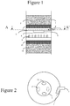
- the figure 1 represents a reactor portion, in which a hydrotreatment reaction is carried out.
- the reactor is composed of an enclosure 1 containing at least one bed of solid catalyst 2.
- the enclosure 1 may have the shape of a closed cylinder at its ends.
- the axis of the cylinder is oriented in the vertical direction.
- the cylinder may have a diameter of between 1 and 10 meters and a height of between 3 and 20 meters.
- the reactor is fed at the top with a reaction fluid, composed of a gas and a liquid, for example a charge of liquid hydrocarbons and hydrogen gas.
- the reaction fluid flows in a downward vertical direction in the chamber 1, in particular under the effect of gravity. In other words, the gas and the liquid flow co-current from top to bottom in the reactor.
- a solid catalyst which may be in the form of extrudates or beads arranged between two grids to form a bed that extends in general on a whole horizontal section of the interior volume of the enclosure. Due to the exothermic reaction, the volume of solid catalyst is divided into several beds. On the figure 1 two beds 2 and 11 of solid catalysts are shown.
- the bed 2 of solid catalyst is placed on a layer 3 of inert solid grains, commonly called "grading".
- Layer 3 is supported by a grid.
- An empty space 4 is located between the grid supporting the layer 3 and the collection tray 6.
- the gas and the liquid flowing through the bed 2 open into the empty space 4 hereinafter called the collection space.
- the collection tray 6 collects the liquid and the gas arriving in the collection space 4.
- the collection tray is the first mechanical member encountered by the liquid and the gas flowing in the collection space 4.
- the collection tray is a horizontal disk that covers the internal section of the enclosure 1.
- an injection rod 5 also called an injection nozzle, makes it possible to introduce a cold fluid from outside the reactor into the collection space 4.
- the cane 5 is composed of a portion of 4.
- the pipe has a single outlet in the space 4, this orifice being located at the end of the pipe.
- the figure 2 represents a view of the reactor of the figure 1 according to AA 'section.
- the shape and, possibly, the dimensions, of the pipe forming the rod 5 are chosen so that the direction of the jet of fluid at the outlet of the rod is directed in a substantially horizontal direction and substantially tangential to the wall of the pregnant 1.
- the Figures 2A and 2B represent two forms of shaped rod 5 according to the invention.
- the end of the rod is in the form of a tube, for example a straight tube that is to say that extends in a straight direction.
- the rod may be in the shape of a cylinder of circular section or of the shape of a truncated cone.
- the end of the rod 5 may be a cylinder of circular section of diameter D.
- the rod 5 may be tube-shaped whose axis is curved.
- cane 5 is a tube of circular section of constant diameter D, the axis 16 of the tube forming an arc concentric to the circle described by the chamber 1 in a horizontal plane.
- the rod 5 is dimensioned to direct the cold fluid in a direction substantially tangential to the wall of the enclosure 1.
- Figures 2A and 2B the end of the rod 5 is formed by a portion of tube which extends along the straight line 14.
- the direction tangential to the wall of the chamber 1 at the outlet orifice of the rod 5 is represented by the straight line 15.
- the direction of the jet of the fluid issuing from the rod is substantially tangential to the internal surface of the wall of the enclosure 1 at the outlet, that is to say that the direction of the jet forms an angle ⁇ between -10 ° and + 10 °, preferably between -5 ° and + 5 °, relative to the tangent to the inner surface of the enclosure 1 at the outlet of the cane 5, that is to say with respect to the line 15.
- the rod 5 is dimensioned to direct the cold fluid in a substantially horizontal direction.
- the direction of the jet of fluid from the rod that is to say the direction in which extends the tube forming the end of the rod at the outlet may be substantially horizontal.
- the direction of the jet forms an angle of between -10 ° and +10, preferably between -5 ° and + 5 °, with respect to a horizontal direction.
- the rod is positioned near the wall of the chamber 1 and near the collecting plate 6.
- the maximum spacing between the wall of the chamber 1 and the rod is between 0 and 40 cm, preferably between 0 and 30 cm.
- the maximum spacing between the surface of the collection tray and the cane is between 0 and 10 cm.
- the length of the cane 5 in the collection space 4 is reduced, for example between 5 and 50 cm, preferably between 5 and 20 cm.
- the orifice located at the end of the nozzle may open at a distance of less than 40 cm, preferably less than 30 cm from the chamber 1.
- the orifice may open at a distance of less than 10 cm. the collection tray.
- the collection plate 6 communicates with a quench box 7 which has the function of mixing the liquid and the gas collected on the plate 6.
- the box 7 may have various geometries.
- the quenching box comprises two inlet orifices 12 communicating with the collection space 4 through the plate 6.
- the fluids collected on the plate 6 flow into the quench box 7 via the orifices 12.
- gaseous and liquid fluids are mixed in the box 7 which may have different internal configurations.
- the mixing box 7 can be produced according to the teaching of the document FR 2824495 .
- the quench box 7 has two outlet orifices 13 communicating with the space below the box 7.
- the orifices 13 are located on the bottom of the box 7, in staggered inlet orifices 12.
- a fluid is injected comprising at least 70%, see 80% by volume of liquid, so that the inertia of the injected liquid generates a better rotational movement of the fluid on the plate 6.
- the cold fluid can be injected by the rod 5 at a speed preferably between 1 and 15 m / s.
- the shape and the dimensions can be adapted according to the pressure at which the cold fluid is available to inject the fluid at a speed of between 1 and 15 ms into the collection space 4.
- the quench box 7 is a distributor plate 9.
- the document US 6,093,373 describes an embodiment of a distributor plate.
- the plate 9 makes it possible to dispense the fluids coming from the box 7 onto the catalyst bed 11.
- the plate 9 is provided with distribution elements, for example chimneys, for distributing the gas and the liquid over the entire surface of the section. of the reactor.
- the plate 8 is composed a perforated plate.
- a layer 10 of inert solid grains, commonly called “grading” can be placed above the bed 11.
- the effectiveness of the system according to the proposed invention is compared to that of a straight rod device described by the figure 3 and to that of a circular cane device described by the figure 4 .
- the figure 3 has a straight rod quenching device similar to that disclosed in the document US 7,314,602 .
- the references of the figure 3 identical to those of the figure 1 designate the same elements.
- the injection rod 5A is a perforated straight tube, which distributes the cold fluid to different locations on the collection tray 6.
- the figure 4 has a quenching device with a circular injection rod 5B, similar to that disclosed by the document US 2004/0234434 .
- a cold model was used to compare the mixing performance between three different quench configurations according to the figure 2 , according to figure 3 and according to the figure 4 .
- the model is composed of a straight cylinder in a vertical position, whose section is 0.48 m in diameter.
- the model has a catalyst bed of 1 m height.
- the empty space 4 where the fluid collection is carried out, above the collection tray 6, has a height of 20 cm.
- the cylinder is fed at the top with a mixture of water and air at 1 bar at 50 ° C. Tests are performed at different surface velocities of gas (Vsg) and liquid (Vsl) at the upper bed entrance.
- the cold quenching fluid is either liquid (water) or gas (air). It is injected with a flow equal to half the flow of the same phase entering the upper bed.
- the quenching fluid is gaseous.
- the superficial velocity of liquid (Vs1) entering the upper bed is greater than 1 cm / s, the quenching fluid is liquid.
- the tests performed at 0.002 m / s, 0.005 m / s and 0.008 m / s are performed with injection of a gas (air) and the tests performed at 0.015 m / s and 0.02 m / s are made with injection of a liquid (water).
- the quench box is identical to the box 7 schematized by the Figures 1 and 2 .
- the orifices 12 and 13 are circular with a diameter of 3 cm.
- the injection rod is a bent tube, with a diameter D equal to 2 cm, bonded to the wall of the column and the collection tray.
- the end of the rod 5 is a straight cylinder whose axis is oriented perfectly tangential to the cylindrical wall of the model.
- the cane 5A is a straight cylinder 3 cm in internal diameter, comprising 6 holes of 1 cm in diameter.
- the cane 5B is circular forms a torus 20 cm in diameter, and 3 cm of internal diameter.
- the torus is equipped with seven exit holes, 1 cm in diameter, oriented at 45 ° to the tangential direction.
- thermocouples For each configuration tested, six thermocouples are positioned at the lower bed entrance and in the "grading" layer. The maximum temperature difference measured by these thermocouples defines the residual temperature difference, noted ⁇ T used to compare the configurations.
- the configuration 1 according to the invention gives better results than the rods according to the configurations 2 and 3, while being lighter, mechanical mounting easier, and less cumbersome.
- the benefits of the device according to the invention are therefore very important.
Description
La présente invention concerne le domaine des réacteurs catalytiques de type lits fixes, qui sont notamment mis en oeuvre dans les opérations d'hydrotraitement de charges d'hydrocarbures. L'invention décrit un système d'injection d'un fluide de trempe dans le réacteur.The present invention relates to the field of fixed bed type catalytic reactors, which are in particular implemented in the hydrotreatment operations of hydrocarbon feeds. The invention describes a system for injecting a quenching fluid into the reactor.
Les réacteurs catalytiques sont mis en oeuvre notamment dans l'industrie pétrolière et pétrochimique pour traiter des effluents hydrocarbonés par réaction d'hydrotraitement. Ces réactions font réagir les composés carbonés avec de l'hydrogène dans des réactions d'hydrogénation, d'hydrodésulfuration, d'hydrogéazotation, d'hydrocraquage, d'hydrodéaromatisation.Catalytic reactors are used in particular in the petroleum and petrochemical industry to treat hydrocarbon effluents by hydrotreatment reaction. These reactions cause the carbon compounds to react with hydrogen in hydrogenation, hydrodesulfurization, hydrogenation, hydrocracking and hydrodearomatization reactions.
Un réacteur catalytique est généralement composé d'une enceinte de forme cylindrique, comportant un ou plusieurs lits catalytiques, c'est à dire un lit de solides, par exemple sous la forme d'extrudé ou de sphère, qui ont pour rôle de catalyser la réaction d'hydrotraitement. Le réacteur est alimenté en tête par un fluide réactionnel, composé de l'effluent hydrocarboné et d'hydrogène.A catalytic reactor is generally composed of a chamber of cylindrical shape, comprising one or more catalytic beds, ie a bed of solids, for example in the form of extruded or sphere, whose role is to catalyze the hydrotreatment reaction. The reactor is fed at the top with a reaction fluid composed of the hydrocarbon effluent and hydrogen.
La nature exothermique des réactions d'hydrotraitement réalisées en raffinage et en pétrochimie nécessite de diviser le volume de solide catalyseur en plusieurs lits et d'effectuer des injections de fluide froid pour refroidir le milieu réactionnel et pour approvisionner le réacteur en réactifs. Le fluide injecté peut être du liquide, en général une coupe d'hydrocarbures, ou un gaz, par exemple de l'hydrogène, selon les applications. Le fluide froid est introduit dans le réacteur au niveau d'un dispositif appelé boite de trempe, également couramment nommé boite de "quench". La technologie de boite de "quench" a pour principal objectif de mélanger les fluides chauds venant du lit supérieur au fluide froid injecté. Une fois les fluides mélangés, ils sont redistribués sur la section de réacteur par un dispositif de distribution, avant de pénétrer dans le lit catalytique situé sous le plateau distributeur.The exothermic nature of the hydrotreatment reactions carried out in refining and in petrochemistry necessitates dividing the solid catalyst volume into several beds and performing cold fluid injections to cool the reaction medium and to supply the reactor with reagents. The injected fluid may be liquid, usually a hydrocarbon cut, or a gas, for example hydrogen, depending on the applications. The cold fluid is introduced into the reactor at a device called quench box, also commonly called "quench" box. The main purpose of the "quench" box technology is to mix the hot fluids from the upper bed with the cold injected fluid. Once the fluids are mixed, they are redistributed on the reactor section by a distribution device, before entering the catalytic bed located under the distributor plate.
Les documents
Les documents
Les documents
Le document
Le document
L'objectif de la présente invention est d'améliorer le mélange du fluide de trempe avec les fluides chaud en positionnant la canne d'injection du fluide en périphérie du réacteur au niveau du plateau collecteur de manière à générer un écoulement rotatif sur le plateau. La présente invention propose d'utiliser une canne d'injection coudée, débouchant au-dessus du plateau collecteur à proximité de l'enceinte du réacteur et produisant un jet dont la direction est sensiblement tangentielle à l'enceinte du réacteur afin de produire de manière simple et efficace un mouvement rotatif du fluide sur le plateau de collecte.The objective of the present invention is to improve the mixing of the quenching fluid with the hot fluids by positioning the injection nozzle of the fluid at the periphery of the reactor at the collector plate so as to generate a rotational flow on the tray. The present invention proposes to use a bent injection nozzle, opening above the collecting tray near the reactor enclosure and producing a jet whose direction is substantially tangential to the reactor enclosure in order to produce simple and effective rotational movement of the fluid on the collection tray.
La présente invention décrit un réacteur catalytique selon la revendication 1. La buse peut déboucher à la paroi de l'enceinte de manière à injecter un fluide selon une direction formant un angle compris entre -10° et +10° par rapport à la direction horizontale.The present invention describes a catalytic reactor according to
L'extrémité de la buse d'injection peut être composée d'une portion tubulaire droite formant un angle compris entre -10° et +10° par rapport à la direction tangente à la paroi de l'enceinte au niveau de l'orifice de la buse.The end of the injection nozzle may be composed of a straight tubular portion forming an angle of between -10 ° and + 10 ° with respect to the direction tangent to the wall of the enclosure at the orifice of the nozzle.
La portion tubulaire droite peut former un angle compris entre -10°et +10° par rapport à la direction horizontale.The straight tubular portion may form an angle between -10 ° and + 10 ° with respect to the horizontal direction.
La buse peut former un tube de longueur comprise entre 5 cm et 50 cm, mesurée dans l'espace de collecte.The nozzle can form a tube of length between 5 cm and 50 cm, measured in the collection space.
La buse peut être disposée à une distance inférieure à 30 cm de l'enceinte et à une distance inférieure à 20 cm du plateau de collecte.The nozzle may be disposed at a distance of less than 30 cm from the enclosure and at a distance of less than 20 cm from the collection tray.
Le réacteur peut comporter un plateau distributeur de gaz et de liquide, disposé sous la boite de trempe.The reactor may comprise a gas and liquid distributor plate disposed under the quench box.
Le réacteur peut comporter une plaque perforée disposée entre la boite de trempe et le plateau distributeur.The reactor may comprise a perforated plate disposed between the quench box and the distributor plate.
L'invention décrit également la mise en oeuvre d'un réacteur selon l'invention, dans laquelle on peut injecter par ladite buse un fluide comportant au moins 70% en volume de liquide. De plus, on peut injecter par ladite buse un fluide à une vitesse comprise entre 1 et 15 m/s.The invention also describes the use of a reactor according to the invention, in which it is possible to inject via said nozzle a fluid comprising at least 70% by volume of liquid. In addition, fluid can be injected through said nozzle at a speed of between 1 and 15 m / s.
L'invention décrit également un procédé selon la revendication 11 pour obtenir un réacteur selon l'une des revendications 1 à 8. Le dispositif selon l'invention permet d'atteindre d'excellentes performances de mélange comme illustré ci-après dans les exemples.The invention also describes a method according to
Par ailleurs, la canne d'injection selon l'invention est d'encombrement réduit par rapport aux solutions proches, notamment par rapport au dispositif décrit par le document
En outre, la présente invention peut être mise en oeuvre dans des installations existantes. En particulier, la présente invention peut remplacer avantageusement un dispositif de trempe à canne d'injection droite, afin d'en améliorer les performances de trempe. De plus, en modifiant la position de la grille supportant le lit de solide catalyseur, il est possible de réduire l'espace de collecte et donc de gagner du volume qui peut être utilisé pour réaliser la réaction.In addition, the present invention can be implemented in existing installations. In particular, the present invention can advantageously replace a quenching device with a straight injection pipe, in order to improve quenching performance. In addition, by changing the position of the grid supporting the bed of solid catalyst, it is possible to reduce the collection space and thus to gain volume that can be used to carry out the reaction.
D'autres caractéristiques et avantages de l'invention seront mieux compris et apparaîtront clairement à la lecture de la description faite ci-après en se référant aux dessins parmi lesquels :
- les
figures 1, 2 ,2A et 2B schématisent un dispositif de tempe dans un réacteur selon l'invention, - les
figures 3 et 4 représentent deux dispositifs de trempe selon l'art antérieur, - la
figure 5 représente des courbes de performance d'un dispositif de trempe selon l'invention et de deux dispositifs de trempe selon l'art antérieur.
- the
Figures 1, 2 ,2A and 2B schematize a temple device in a reactor according to the invention, - the
Figures 3 and 4 represent two quenching devices according to the prior art, - the
figure 5 represents performance curves of a quenching device according to the invention and two quenching devices according to the prior art.
La
Le lit 2 de solide catalyseur est posé sur une couche 3 de grains solides inertes, couramment nommé "grading". La couche 3 est supportée par une grille. Un espace vide 4 est situé entre la grille supportant la couche 3 et le plateau de collecte 6. Le gaz et le liquide s'écoulant à travers le lit 2 débouchent dans l'espace vide 4 appelé ci-après l'espace de collecte. Le plateau de collecte 6 permet de collecter le liquide et le gaz arrivant dans l'espace de collecte 4. Ainsi, le plateau de collecte constitue le premier organe mécanique rencontré par le liquide et le gaz circulant dans l'espace de collecte 4. Par exemple le plateau de collecte est un disque horizontal qui couvre la section interne de l'enceinte 1.The
Selon l'invention, une canne d'injection 5, également nommée buse d'injection, permet d'introduire un fluide froid depuis l'extérieur du réacteur dans l'espace de collecte 4. La canne 5 est composée d'une portion de tuyau qui débouche dans l'espace de collecte 4. De préférence, le tuyau comporte un seul orifice de sortie dans l'espace 4, cet orifice étant situé au niveau de l'extrémité du tuyau.According to the invention, an
La
La canne 5 est dimensionnée pour diriger le fluide froid dans une direction sensiblement tangentielle à la paroi de l'enceinte 1. En référence aux
De plus, la canne 5 est dimensionnée pour diriger le fluide froid selon une direction sensiblement horizontale. Par exemple, la direction du jet de fluide issu de la canne, c'est-à-dire la direction dans laquelle s'étend le tube formant l'extrémité de la canne au niveau de la sortie peut être sensiblement horizontale. Par exemple la direction du jet forme un angle compris entre -10° et +10, de préférence entre -5° et +5°, par rapport à une direction horizontale.In addition, the
La canne est positionnée à proximité de la paroi de l'enceinte 1 et à proximité du plateau de collecte 6. Par exemple l'écartement maximum entre la paroi de l'enceinte 1 et la canne est compris entre 0 et 40 cm, de préférence entre 0 et 30 cm. Par exemple, l'écartement maximum entre la surface du plateau de collecte et la canne est compris entre 0 et 10 cm. De préférence, la longueur de la canne 5 dans l'espace de collecte 4 est réduite, par exemple compris entre 5 et 50 cm, de préférence entre 5 et 20 cm. Ainsi, l'orifice situé à l'extrémité de la buse peut déboucher à une distance inférieure à 40 cm, de préférence inférieure à 30 cm de l'enceinte 1. De plus, l'orifice peut déboucher à une distance inférieure à 10 cm du plateau de collecte.The rod is positioned near the wall of the
La simplicité de la forme de la canne 5 et les dimensions réduites de la canne 5 par rapport à la taille du réacteur permettent de mettre en oeuvre le système d'injection selon l'invention dans le cadre d'un remodelage, couramment nommé "revamping", d'une installation. En effet, on peut installer la canne 5 en lieu et place d'une canne dans un réacteur existant, par exemple un réacteur décrit par les documents
En référence à la
L'injection horizontale et tangentielle du fluide froid par la canne 5 sur le plateau 6 permet de générer un écoulement rotatif du fluide sur le plateau 6. Du fait de l'emplacement de la canne à proximité de l'enceinte 1 et de la position centrale des orifices 12, l'écoulement rotatif s'effectue selon une spirale depuis l'extérieure vers l'intérieur du plateau 6. Cet écoulement rotatif améliore efficacement le mélange et l'homogénéisation des températures entre les fluides chauds issus du lit 2 et le fluide froid injecté par la canne 5. De préférence, on injecte un fluide comportant au moins 70%, voir 80% en volume de liquide, afin que l'inertie du liquide injecté engendre un meilleur mouvement de rotation du fluide sur le plateau 6. De plus, pour assurer le mouvement de rotation, le fluide froid peut être injecté par la canne 5 à une vitesse comprise de préférence entre 1 et 15 m/s. par exemple, la forme et les dimensions peuvent être adaptée en fonction de la pression à laquelle le fluide froid est disponible pour injecter le fluide à une vitesse comprise entre 1 et 15 ms dans l'espace de collecte 4.The horizontal and tangential injection of the cold fluid by the
En référence à la
Les exemples présentés ci-après permettent de comparer les performances d'une injection d'un fluide de trempe dans un réacteur selon l'invention par rapport à l'art antérieur.The examples presented below make it possible to compare the performance of an injection of a quenching fluid in a reactor according to the invention compared to the prior art.
L'efficacité du système selon l'invention proposée est comparée à celle d'un dispositif à canne droite décrit par la
La
La
Une maquette froide a été utilisée pour comparer les performances de mélange entre trois configurations distinctes de trempe selon la
La maquette est composée d'un cylindre droit en position verticale, dont la section a 0,48 m de diamètre. La maquette comporte un lit de catalyseur de 1 m de hauteur. L'espace vide 4 où est réalisée la collecte des fluides, au dessus du plateau de collecte 6, a une hauteur de 20 cm.The model is composed of a straight cylinder in a vertical position, whose section is 0.48 m in diameter. The model has a catalyst bed of 1 m height. The
Le cylindre est alimenté en tête par un mélange d'eau et d'air sous 1 bar à 50°C. Des essais sont réalisés à différentes vitesses superficielles de gaz (Vsg) et de liquide (Vsl) en entrée de lit supérieur.The cylinder is fed at the top with a mixture of water and air at 1 bar at 50 ° C. Tests are performed at different surface velocities of gas (Vsg) and liquid (Vsl) at the upper bed entrance.
Le fluide de trempe froid est soit du liquide (de l'eau) soit du gaz (de l'air). Il est injecté avec un débit égal à la moitié du débit de la même phase entrant dans le lit supérieur. Lorsque la vitesse superficielle de liquide (Vsl) entrant dans le lit supérieur est inférieure à 1 cm/s, le fluide de trempe est gazeux. Lorsque la vitesse superficielle de liquide (Vsl) entrant dans le lit supérieur est supérieure à 1 cm/s, le fluide de trempe est liquide. Pour les trois configurations, les tests effectués à 0,002 m/s, 0,005 m/s et 0,008 m/s sont réalisés avec injection d'un gaz (de l'air) et les tests effectués à 0,015 m/s et 0,02 m/s sont réalisés avec injection d'un liquide (de l'eau).The cold quenching fluid is either liquid (water) or gas (air). It is injected with a flow equal to half the flow of the same phase entering the upper bed. When the superficial velocity of liquid (Vs1) entering the upper bed is less than 1 cm / sec, the quenching fluid is gaseous. When the superficial velocity of liquid (Vs1) entering the upper bed is greater than 1 cm / s, the quenching fluid is liquid. For the three configurations, the tests performed at 0.002 m / s, 0.005 m / s and 0.008 m / s are performed with injection of a gas (air) and the tests performed at 0.015 m / s and 0.02 m / s are made with injection of a liquid (water).
Dans les trois configurations étudiées, on utilise la même boite de trempe, seule la forme de la canne d'injection du fluide de trempe diffère d'une configuration à une autre.In the three configurations studied, the same quench box is used, only the shape of the injection pipe of the quenching fluid differs from one configuration to another.
Pour les trois configurations, la boite de trempe est identique à la boite 7 schématisée par les
Dans la configuration 1 selon les
Dans la configuration 2 selon la
Dans la configuration 3 selon la
Pour chaque configuration testée, six thermocouples sont positionnés en entrée de lit inférieur et dans la couche de "grading". L'écart maximal de température mesuré par ces thermocouples définit l'écart de température résiduel, noté ΔT servant à comparer les configurations.For each configuration tested, six thermocouples are positioned at the lower bed entrance and in the "grading" layer. The maximum temperature difference measured by these thermocouples defines the residual temperature difference, noted ΔT used to compare the configurations.
Les résultats sont présentés sur la
On remarque plusieurs points importants sur les résultats donnés par la
- les meilleures performances sont obtenues avec la canne d'injection en tube coudé selon selon l'invention,
- les performances obtenues avec la canne coudée de la
configuration 1 sont meilleures avec un fluide de trempe liquide (Vsl>1 cm/s) qu'avec un fluide de trempe gazeux. Ceci est lié à l'inertie du liquide froid, plus importante que celle d'un gaz froid, ce qui permet de mettre en rotation plus facilement le liquide sur le plateau de collecte. - les performances obtenues avec la canne de forme torique de la
configuration 3 sont proches des résultats obtenus avec la canne en tube coudé dans laconfiguration 1 selon l'invention, avec un fluide de trempe gazeux, et légèrement moins bonnes avec un fluide de trempe liquide.
- the best performances are obtained with the injection tube in elbow tube according to the invention,
- the performances obtained with the bent rod of the
configuration 1 are better with a liquid quenching fluid (Vs1> 1 cm / s) than with a gaseous quenching fluid. This is related to the inertia of the cold liquid, greater than that of a cold gas, which makes it easier to rotate the liquid on the collection tray. - the performances obtained with the toroidal rod of the
configuration 3 are close to the results obtained with the rod elbow tube in theconfiguration 1 according to the invention, with a gaseous quenching fluid, and slightly worse with a liquid quenching fluid .
Par conséquent, la configuration 1 selon l'invention donne de meilleurs résultats que les cannes selon les configurations 2 et 3, tout en étant plus légère, de montage mécanique plus aisé, et moins encombrant. Les bénéfices du dispositif selon l'invention sont donc très importants.Therefore, the
Claims (11)
- A catalytic reactor comprising an enclosure (1) comprising at least two beds of solid catalyst (2; 11) separated by an intermediate zone comprising a collector plate (6) cooperating with a quench box (7) disposed below the collector plate (6), the reactor comprising a nozzle (5) for injecting a quench fluid, characterized in that the nozzle (5) is disposed in a collecting region (4) located in the intermediate zone above the collector plate (6) and at the periphery of the reactor, in that the injection nozzle (5) consists of a bent tube comprising a single orifice discharging into the collecting region, the orifice being located at the end of the tube, in that the maximum distance between the enclosure (1) and the injection nozzle (5) is in the range 0 to 40 cm, and in that the end of the injection nozzle (5) comprises a tubular portion configured so as to inject the quench fluid into the collecting region (4) in a substantially horizontal direction and forming an angle in the range -10° to +10° with respect to the direction tangential to the inner surface of the wall of the enclosure (1) at the level of the outlet of the tubular portion so as to generate a rotational flow over the collector plate (6).
- A reactor according to claim 1, characterized in that the nozzle (5) discharges at the wall of the enclosure (1) so as to inject a fluid in a direction forming an angle in the range -10° to +10° with respect to the horizontal direction.
- A reactor according to claim 1 or claim 2, characterized in that the end of the injection nozzle (5) is composed of a straight tubular portion forming an angle (θ) in the range - 10° to +10° with respect to the direction tangential to the wall of the enclosure (1) at the level of the nozzle orifice.
- A reactor according to claim 3, characterized in that the straight tubular portion forms an angle in the range -10° to +10° with respect to the horizontal direction.
- A reactor according to one of the preceding claims, characterized in that the nozzle (5) forms a tube with a length in the range 5 cm to 50 cm, measured in the collecting region (4).
- A reactor according to one of the preceding claims, characterized in that the nozzle (5) is disposed at a distance of less than 30 cm from the enclosure and at a distance of less than 20 cm from the collector plate (6).
- A reactor according to one of the preceding claims, comprising a distributor plate (9) for gas and liquid disposed beneath the quench box (7).
- A reactor according to claim 7, comprising a perforated plate (8) disposed between the quench box (7) and the distributor plate (9).
- A method for deploying a reactor according to one of claims 1 to 8, characterized in that a fluid comprising at least 70% by volume of liquid is injected via said nozzle (5).
- A method according to claim 9, in which a fluid is injected via said nozzle (5) at a rate in the range 1 to 15 m/s.
- A method of obtaining a reactor according to one of claims 1 to 8, in which an existing reactor is revamped by replacing the old nozzle with an injection nozzle (5) the end of which comprises a tubular portion configured so as to inject the fluid into the collecting region in a substantially horizontal direction and forming an angle in the range -10° to +10° with respect to the direction tangential to the wall of the enclosure at said tubular portion.
Priority Applications (1)
| Application Number | Priority Date | Filing Date | Title |
|---|---|---|---|
| HRP20171967TT HRP20171967T1 (en) | 2012-04-04 | 2017-12-19 | Catalytic reactor with quenching device provided with tangential injection of a quenching fluid |
Applications Claiming Priority (1)
| Application Number | Priority Date | Filing Date | Title |
|---|---|---|---|
| FR1201009A FR2989006B1 (en) | 2012-04-04 | 2012-04-04 | CATALYTIC REACTOR WITH TEMPERATURE DEVICE PROVIDED WITH TANGENTIAL INJECTION OF A TEMPERED FLUID |
Publications (2)
| Publication Number | Publication Date |
|---|---|
| EP2647425A1 EP2647425A1 (en) | 2013-10-09 |
| EP2647425B1 true EP2647425B1 (en) | 2017-10-04 |
Family
ID=47748555
Family Applications (1)
| Application Number | Title | Priority Date | Filing Date |
|---|---|---|---|
| EP13305193.8A Active EP2647425B1 (en) | 2012-04-04 | 2013-02-21 | Catalytic reactor with quenching device provided with tangential injection of a quenching fluid |
Country Status (10)
| Country | Link |
|---|---|
| EP (1) | EP2647425B1 (en) |
| JP (1) | JP6173744B2 (en) |
| KR (1) | KR102002651B1 (en) |
| CN (1) | CN103357356B (en) |
| ES (1) | ES2650082T3 (en) |
| FR (1) | FR2989006B1 (en) |
| HR (1) | HRP20171967T1 (en) |
| PT (1) | PT2647425T (en) |
| RU (1) | RU2627389C2 (en) |
| SG (2) | SG193774A1 (en) |
Families Citing this family (6)
| Publication number | Priority date | Publication date | Assignee | Title |
|---|---|---|---|---|
| EP2954945B1 (en) | 2014-06-11 | 2016-06-08 | Neste Oyj | Method and apparatus for mixing fluids |
| FR3034325B1 (en) * | 2015-04-01 | 2017-03-17 | Ifp Energies Now | COMPACT DISPOSITION OF MIXING AND COMBINED DISTRIBUTION |
| FR3034324B1 (en) * | 2015-04-01 | 2017-03-17 | Ifp Energies Now | MIXING AND DISPENSING DEVICE COMPRISING A DISPENSING TRAY WITH PERIPHERAL OPENINGS |
| RU2674950C1 (en) * | 2018-04-09 | 2018-12-13 | Игорь Анатольевич Мнушкин | Catalytic reactor |
| US10589244B1 (en) * | 2019-02-07 | 2020-03-17 | Uop Llc | Hydroprocessing reactor internals having reduced height |
| US11298670B2 (en) * | 2020-04-24 | 2022-04-12 | Uop Llc | Compact quench zone reactor internals |
Family Cites Families (21)
| Publication number | Priority date | Publication date | Assignee | Title |
|---|---|---|---|---|
| US3592612A (en) * | 1966-11-02 | 1971-07-13 | John H Ballard | Two-stage apparatus for mixing fluids in concurrent downflow relationship |
| JPS62194432U (en) * | 1986-05-30 | 1987-12-10 | ||
| US5403560A (en) | 1993-05-13 | 1995-04-04 | Texaco Inc. | Fluids mixing and distributing apparatus |
| DK171572B1 (en) * | 1994-01-12 | 1997-01-20 | Topsoe Haldor As | Method and device for mixing gases |
| DE69501154T2 (en) * | 1994-03-01 | 1998-07-02 | Methanol Casale Sa | MIXING DEVICE FOR FLOWING GASES AT DIFFERENT TEMPERATURES, ESPECIALLY FOR HETEROGENEOUS, EXOTHERMAL SYNTHESIS REACTORS |
| FR2745202B1 (en) | 1996-02-27 | 1998-04-30 | Inst Francais Du Petrole | TRAY FOR DISTRIBUTING A POLYPHASIC MIXTURE THROUGH A CATALYTIC BED |
| US6098965A (en) | 1996-06-04 | 2000-08-08 | Fluor Corporation | Reactor distribution apparatus and quench zone mixing apparatus |
| US5837208A (en) | 1996-06-12 | 1998-11-17 | Uop | Hydroprocessing reactor mixer/distributor |
| US5935413A (en) | 1997-12-03 | 1999-08-10 | Mobil Oil Corporation | Interbed gas-liquid mixing system for cocurrent downflow reactors |
| US6183702B1 (en) * | 1998-12-21 | 2001-02-06 | Chevron U.S.A. Inc. | Fluid distributor assembly for a multi-bed, downflow catalytic reactor |
| AU2002217112A1 (en) | 2000-12-11 | 2002-06-24 | Shell Internationale Research Maatschappij B.V. | Multiple bed downflow reactor |
| FR2824495B1 (en) * | 2001-05-09 | 2005-03-04 | Inst Francais Du Petrole | REACTIONAL REINFORCING SHAPE EXTENDED ALONG AN AXIS CONTAINING AT LEAST ONE SOLID CATALYST BED AND AT LEAST ONE CONTACT, MIXING AND TEMPERED BOX |
| FR2826594B1 (en) * | 2001-07-02 | 2003-09-26 | Inst Francais Du Petrole | CONTACT, MIXTURE AND TEMPERED FLUID BOX HAVING AT LEAST ONE PERIPHERAL ANNULAR OUTPUT AND REACTIONAL ENCLOSURE IN AN ELONGATE SHAPE ALONG A AXIS COMPRISING SAID BOX |
| CN100355494C (en) * | 2002-11-08 | 2007-12-19 | 莫藤米勒有限公司 | Mixing device for two-phase concurrent vessels |
| US7074372B2 (en) * | 2003-05-16 | 2006-07-11 | Exxonmobil Research And Engineering Company | Multiphase mixing device with improved quench injection for inducing rotational flow |
| US20070248510A1 (en) * | 2006-04-25 | 2007-10-25 | Dean Anne M | Dual gas-liquid spargers for catalytic processing units |
| JP5412054B2 (en) | 2008-05-02 | 2014-02-12 | 株式会社ワコール | Warp knitted fabric for clothing, production method thereof, and knitted structure of warp knitted fabric for clothing |
| US8181942B2 (en) * | 2008-06-26 | 2012-05-22 | Uop Llc | Liquid redistribution device for multibed reactors |
| US8017095B2 (en) | 2009-05-29 | 2011-09-13 | Chevron U.S.A. Inc. | Mixing device for a down-flow reactor |
| FR2952835B1 (en) * | 2009-11-20 | 2011-12-09 | Inst Francais Du Petrole | COMPACT DEVICE FOR MIXING FLUIDS IN A DOWNFLOW REACTOR |
| US8673246B2 (en) * | 2011-03-23 | 2014-03-18 | Uop Llc | Process for contacting one or more fluids and a reactor relating thereto |
-
2012
- 2012-04-04 FR FR1201009A patent/FR2989006B1/en active Active
-
2013
- 2013-02-21 ES ES13305193.8T patent/ES2650082T3/en active Active
- 2013-02-21 PT PT133051938T patent/PT2647425T/en unknown
- 2013-02-21 EP EP13305193.8A patent/EP2647425B1/en active Active
- 2013-04-02 JP JP2013076508A patent/JP6173744B2/en active Active
- 2013-04-03 CN CN201310115316.0A patent/CN103357356B/en active Active
- 2013-04-03 SG SG2013025101A patent/SG193774A1/en unknown
- 2013-04-03 RU RU2013114974A patent/RU2627389C2/en active
- 2013-04-03 SG SG10201505175UA patent/SG10201505175UA/en unknown
- 2013-04-04 KR KR1020130037059A patent/KR102002651B1/en active IP Right Grant
-
2017
- 2017-12-19 HR HRP20171967TT patent/HRP20171967T1/en unknown
Non-Patent Citations (1)
| Title |
|---|
| None * |
Also Published As
| Publication number | Publication date |
|---|---|
| JP6173744B2 (en) | 2017-08-02 |
| JP2013223862A (en) | 2013-10-31 |
| SG193774A1 (en) | 2013-10-30 |
| RU2627389C2 (en) | 2017-08-08 |
| EP2647425A1 (en) | 2013-10-09 |
| RU2013114974A (en) | 2014-10-10 |
| ES2650082T3 (en) | 2018-01-16 |
| KR20130112807A (en) | 2013-10-14 |
| FR2989006A1 (en) | 2013-10-11 |
| KR102002651B1 (en) | 2019-07-23 |
| PT2647425T (en) | 2017-12-01 |
| HRP20171967T1 (en) | 2018-02-09 |
| FR2989006B1 (en) | 2016-11-18 |
| CN103357356A (en) | 2013-10-23 |
| SG10201505175UA (en) | 2015-08-28 |
| CN103357356B (en) | 2018-01-23 |
Similar Documents
| Publication | Publication Date | Title |
|---|---|---|
| EP2647425B1 (en) | Catalytic reactor with quenching device provided with tangential injection of a quenching fluid | |
| CA2925656C (en) | Mixing and distribution device with mixture and exchange zones | |
| FR3001899A1 (en) | DEVICE FOR INJECTING AND MIXING FLUIDS IN A DOWNFLOW REACTOR. | |
| EP2151277B1 (en) | Up-flow co-current gas-liquid reactor with distribution plate | |
| WO2017080756A1 (en) | Filtering and distribution device for a catalytic reactor | |
| CA2925657C (en) | Mixing and distribution device including a distribution tray with peripheral openings | |
| EP2813283B1 (en) | Device for dispensing a fluid | |
| FR2883200A1 (en) | DEVICE FOR MIXING AND DISTRIBUTING A GAS AND A LIQUID BEFORE A GRANULAR BED | |
| FR3051375A1 (en) | FILTRATION AND DISTRIBUTION DEVICE FOR CATALYTIC REACTOR. | |
| EP0107986A1 (en) | Process and apparatus for the hydroconversion of hydrocarbons | |
| FR2952835A1 (en) | COMPACT DEVICE FOR MIXING FLUIDS IN A DOWNFLOW REACTOR | |
| EP3277417A1 (en) | Compact device for the combined mixing and distribution of fluids for a catalytic reactor | |
| EP2773450A1 (en) | Distributor plate for a gas/liquid mixture equipped with distributor elements largely insensitive to the lack of horizontality | |
| FR2993794A1 (en) | CATALYST CONTINUOUS REGENERATION REACTOR WITH GAS MIXING AND GAS DISTRIBUTION CASE IN THE OXYCHLORIZATION AREA | |
| EP2162207B1 (en) | Enclosure containing a granular bed and a distribution of a gaseous phase and a liquid phase flowing according to an ascending flow in said enclosure | |
| EP3618947B1 (en) | Novel device for distributing a polyphase mixture in a chamber comprising a fluidised medium | |
| EP2760575B1 (en) | Reactor with a distribution tray for distributing a polyphasic mixture with inclined peripheral conduits | |
| FR2818559A1 (en) | DEVICE FOR PROVIDING A SEPARATE INJECTION AND A HOMOGENEOUS DISTRIBUTION OF TWO FLUIDS | |
| EP1646444B1 (en) | Valve plate for distributing a gaseous and liquid phases | |
| CA3020940A1 (en) | Removable basket for catalytic reactor | |
| EP3536398A1 (en) | Mixing apparatus of a fluid for a catalytic bed | |
| FR3066411B1 (en) | MIXING AND DISPENSING DEVICE WITH FLUID BALANCING SYSTEM | |
| EP2078558B1 (en) | Device for reducing the effect of the speed of impact of a fluid on a fixed bed of solid particles, reaction chamber equipped with such a device and uses thereof | |
| FR3072306A1 (en) | DEVICE FOR MIXING AND DISPENSING WITH LONGITUDINAL OPENING | |
| FR3066409A1 (en) | MIXING AND DISPENSING DEVICE WITH IMPROVED TEMPERATURE FLUID INJECTION |
Legal Events
| Date | Code | Title | Description |
|---|---|---|---|
| PUAI | Public reference made under article 153(3) epc to a published international application that has entered the european phase |
Free format text: ORIGINAL CODE: 0009012 |
|
| AK | Designated contracting states |
Kind code of ref document: A1 Designated state(s): AL AT BE BG CH CY CZ DE DK EE ES FI FR GB GR HR HU IE IS IT LI LT LU LV MC MK MT NL NO PL PT RO RS SE SI SK SM TR |
|
| AX | Request for extension of the european patent |
Extension state: BA ME |
|
| 17P | Request for examination filed |
Effective date: 20140409 |
|
| RBV | Designated contracting states (corrected) |
Designated state(s): AL AT BE BG CH CY CZ DE DK EE ES FI FR GB GR HR HU IE IS IT LI LT LU LV MC MK MT NL NO PL PT RO RS SE SI SK SM TR |
|
| GRAP | Despatch of communication of intention to grant a patent |
Free format text: ORIGINAL CODE: EPIDOSNIGR1 |
|
| RIC1 | Information provided on ipc code assigned before grant |
Ipc: C10G 49/00 20060101ALN20170413BHEP Ipc: B01J 8/04 20060101AFI20170413BHEP |
|
| INTG | Intention to grant announced |
Effective date: 20170512 |
|
| GRAS | Grant fee paid |
Free format text: ORIGINAL CODE: EPIDOSNIGR3 |
|
| GRAA | (expected) grant |
Free format text: ORIGINAL CODE: 0009210 |
|
| AK | Designated contracting states |
Kind code of ref document: B1 Designated state(s): AL AT BE BG CH CY CZ DE DK EE ES FI FR GB GR HR HU IE IS IT LI LT LU LV MC MK MT NL NO PL PT RO RS SE SI SK SM TR |
|
| REG | Reference to a national code |
Ref country code: GB Ref legal event code: FG4D Free format text: NOT ENGLISH |
|
| REG | Reference to a national code |
Ref country code: CH Ref legal event code: EP |
|
| REG | Reference to a national code |
Ref country code: AT Ref legal event code: REF Ref document number: 933482 Country of ref document: AT Kind code of ref document: T Effective date: 20171015 |
|
| RAP2 | Party data changed (patent owner data changed or rights of a patent transferred) |
Owner name: IFP ENERGIES NOUVELLES |
|
| REG | Reference to a national code |
Ref country code: IE Ref legal event code: FG4D Free format text: LANGUAGE OF EP DOCUMENT: FRENCH |
|
| REG | Reference to a national code |
Ref country code: DE Ref legal event code: R096 Ref document number: 602013027413 Country of ref document: DE |
|
| REG | Reference to a national code |
Ref country code: PT Ref legal event code: SC4A Ref document number: 2647425 Country of ref document: PT Date of ref document: 20171201 Kind code of ref document: T Free format text: AVAILABILITY OF NATIONAL TRANSLATION Effective date: 20171124 |
|
| REG | Reference to a national code |
Ref country code: RO Ref legal event code: EPE Ref country code: HR Ref legal event code: TUEP Ref document number: P20171967 Country of ref document: HR |
|
| REG | Reference to a national code |
Ref country code: NL Ref legal event code: FP |
|
| REG | Reference to a national code |
Ref country code: ES Ref legal event code: FG2A Ref document number: 2650082 Country of ref document: ES Kind code of ref document: T3 Effective date: 20180116 |
|
| REG | Reference to a national code |
Ref country code: HR Ref legal event code: T1PR Ref document number: P20171967 Country of ref document: HR |
|
| REG | Reference to a national code |
Ref country code: FR Ref legal event code: PLFP Year of fee payment: 6 |
|
| REG | Reference to a national code |
Ref country code: LT Ref legal event code: MG4D |
|
| PG25 | Lapsed in a contracting state [announced via postgrant information from national office to epo] |
Ref country code: NO Free format text: LAPSE BECAUSE OF FAILURE TO SUBMIT A TRANSLATION OF THE DESCRIPTION OR TO PAY THE FEE WITHIN THE PRESCRIBED TIME-LIMIT Effective date: 20180104 Ref country code: FI Free format text: LAPSE BECAUSE OF FAILURE TO SUBMIT A TRANSLATION OF THE DESCRIPTION OR TO PAY THE FEE WITHIN THE PRESCRIBED TIME-LIMIT Effective date: 20171004 Ref country code: LT Free format text: LAPSE BECAUSE OF FAILURE TO SUBMIT A TRANSLATION OF THE DESCRIPTION OR TO PAY THE FEE WITHIN THE PRESCRIBED TIME-LIMIT Effective date: 20171004 Ref country code: SE Free format text: LAPSE BECAUSE OF FAILURE TO SUBMIT A TRANSLATION OF THE DESCRIPTION OR TO PAY THE FEE WITHIN THE PRESCRIBED TIME-LIMIT Effective date: 20171004 |
|
| PG25 | Lapsed in a contracting state [announced via postgrant information from national office to epo] |
Ref country code: RS Free format text: LAPSE BECAUSE OF FAILURE TO SUBMIT A TRANSLATION OF THE DESCRIPTION OR TO PAY THE FEE WITHIN THE PRESCRIBED TIME-LIMIT Effective date: 20171004 Ref country code: BG Free format text: LAPSE BECAUSE OF FAILURE TO SUBMIT A TRANSLATION OF THE DESCRIPTION OR TO PAY THE FEE WITHIN THE PRESCRIBED TIME-LIMIT Effective date: 20180104 Ref country code: LV Free format text: LAPSE BECAUSE OF FAILURE TO SUBMIT A TRANSLATION OF THE DESCRIPTION OR TO PAY THE FEE WITHIN THE PRESCRIBED TIME-LIMIT Effective date: 20171004 Ref country code: IS Free format text: LAPSE BECAUSE OF FAILURE TO SUBMIT A TRANSLATION OF THE DESCRIPTION OR TO PAY THE FEE WITHIN THE PRESCRIBED TIME-LIMIT Effective date: 20180204 |
|
| REG | Reference to a national code |
Ref country code: GR Ref legal event code: EP Ref document number: 20170403546 Country of ref document: GR Effective date: 20180518 |
|
| REG | Reference to a national code |
Ref country code: DE Ref legal event code: R097 Ref document number: 602013027413 Country of ref document: DE |
|
| PG25 | Lapsed in a contracting state [announced via postgrant information from national office to epo] |
Ref country code: DK Free format text: LAPSE BECAUSE OF FAILURE TO SUBMIT A TRANSLATION OF THE DESCRIPTION OR TO PAY THE FEE WITHIN THE PRESCRIBED TIME-LIMIT Effective date: 20171004 Ref country code: EE Free format text: LAPSE BECAUSE OF FAILURE TO SUBMIT A TRANSLATION OF THE DESCRIPTION OR TO PAY THE FEE WITHIN THE PRESCRIBED TIME-LIMIT Effective date: 20171004 Ref country code: CZ Free format text: LAPSE BECAUSE OF FAILURE TO SUBMIT A TRANSLATION OF THE DESCRIPTION OR TO PAY THE FEE WITHIN THE PRESCRIBED TIME-LIMIT Effective date: 20171004 Ref country code: SK Free format text: LAPSE BECAUSE OF FAILURE TO SUBMIT A TRANSLATION OF THE DESCRIPTION OR TO PAY THE FEE WITHIN THE PRESCRIBED TIME-LIMIT Effective date: 20171004 |
|
| PLBE | No opposition filed within time limit |
Free format text: ORIGINAL CODE: 0009261 |
|
| STAA | Information on the status of an ep patent application or granted ep patent |
Free format text: STATUS: NO OPPOSITION FILED WITHIN TIME LIMIT |
|
| PG25 | Lapsed in a contracting state [announced via postgrant information from national office to epo] |
Ref country code: SM Free format text: LAPSE BECAUSE OF FAILURE TO SUBMIT A TRANSLATION OF THE DESCRIPTION OR TO PAY THE FEE WITHIN THE PRESCRIBED TIME-LIMIT Effective date: 20171004 Ref country code: IT Free format text: LAPSE BECAUSE OF FAILURE TO SUBMIT A TRANSLATION OF THE DESCRIPTION OR TO PAY THE FEE WITHIN THE PRESCRIBED TIME-LIMIT Effective date: 20171004 Ref country code: PL Free format text: LAPSE BECAUSE OF FAILURE TO SUBMIT A TRANSLATION OF THE DESCRIPTION OR TO PAY THE FEE WITHIN THE PRESCRIBED TIME-LIMIT Effective date: 20171004 |
|
| 26N | No opposition filed |
Effective date: 20180705 |
|
| REG | Reference to a national code |
Ref country code: CH Ref legal event code: PL |
|
| PG25 | Lapsed in a contracting state [announced via postgrant information from national office to epo] |
Ref country code: MC Free format text: LAPSE BECAUSE OF FAILURE TO SUBMIT A TRANSLATION OF THE DESCRIPTION OR TO PAY THE FEE WITHIN THE PRESCRIBED TIME-LIMIT Effective date: 20171004 Ref country code: MT Free format text: LAPSE BECAUSE OF FAILURE TO SUBMIT A TRANSLATION OF THE DESCRIPTION OR TO PAY THE FEE WITHIN THE PRESCRIBED TIME-LIMIT Effective date: 20171004 |
|
| REG | Reference to a national code |
Ref country code: IE Ref legal event code: MM4A |
|
| PG25 | Lapsed in a contracting state [announced via postgrant information from national office to epo] |
Ref country code: LU Free format text: LAPSE BECAUSE OF NON-PAYMENT OF DUE FEES Effective date: 20180221 Ref country code: LI Free format text: LAPSE BECAUSE OF NON-PAYMENT OF DUE FEES Effective date: 20180228 Ref country code: CH Free format text: LAPSE BECAUSE OF NON-PAYMENT OF DUE FEES Effective date: 20180228 Ref country code: SI Free format text: LAPSE BECAUSE OF FAILURE TO SUBMIT A TRANSLATION OF THE DESCRIPTION OR TO PAY THE FEE WITHIN THE PRESCRIBED TIME-LIMIT Effective date: 20171004 |
|
| PG25 | Lapsed in a contracting state [announced via postgrant information from national office to epo] |
Ref country code: IE Free format text: LAPSE BECAUSE OF NON-PAYMENT OF DUE FEES Effective date: 20180221 |
|
| REG | Reference to a national code |
Ref country code: HR Ref legal event code: ODRP Ref document number: P20171967 Country of ref document: HR Payment date: 20190129 Year of fee payment: 7 |
|
| REG | Reference to a national code |
Ref country code: AT Ref legal event code: UEP Ref document number: 933482 Country of ref document: AT Kind code of ref document: T Effective date: 20171004 |
|
| REG | Reference to a national code |
Ref country code: HR Ref legal event code: ODRP Ref document number: P20171967 Country of ref document: HR Payment date: 20200207 Year of fee payment: 8 |
|
| PG25 | Lapsed in a contracting state [announced via postgrant information from national office to epo] |
Ref country code: TR Free format text: LAPSE BECAUSE OF FAILURE TO SUBMIT A TRANSLATION OF THE DESCRIPTION OR TO PAY THE FEE WITHIN THE PRESCRIBED TIME-LIMIT Effective date: 20171004 |
|
| PG25 | Lapsed in a contracting state [announced via postgrant information from national office to epo] |
Ref country code: HU Free format text: LAPSE BECAUSE OF FAILURE TO SUBMIT A TRANSLATION OF THE DESCRIPTION OR TO PAY THE FEE WITHIN THE PRESCRIBED TIME-LIMIT; INVALID AB INITIO Effective date: 20130221 |
|
| PG25 | Lapsed in a contracting state [announced via postgrant information from national office to epo] |
Ref country code: MK Free format text: LAPSE BECAUSE OF NON-PAYMENT OF DUE FEES Effective date: 20171004 Ref country code: CY Free format text: LAPSE BECAUSE OF FAILURE TO SUBMIT A TRANSLATION OF THE DESCRIPTION OR TO PAY THE FEE WITHIN THE PRESCRIBED TIME-LIMIT Effective date: 20171004 |
|
| PG25 | Lapsed in a contracting state [announced via postgrant information from national office to epo] |
Ref country code: AL Free format text: LAPSE BECAUSE OF FAILURE TO SUBMIT A TRANSLATION OF THE DESCRIPTION OR TO PAY THE FEE WITHIN THE PRESCRIBED TIME-LIMIT Effective date: 20171004 |
|
| REG | Reference to a national code |
Ref country code: HR Ref legal event code: ODRP Ref document number: P20171967 Country of ref document: HR Payment date: 20210209 Year of fee payment: 9 |
|
| REG | Reference to a national code |
Ref country code: HR Ref legal event code: ODRP Ref document number: P20171967 Country of ref document: HR Payment date: 20220209 Year of fee payment: 10 |
|
| REG | Reference to a national code |
Ref country code: HR Ref legal event code: ODRP Ref document number: P20171967 Country of ref document: HR Payment date: 20230208 Year of fee payment: 11 |
|
| PGFP | Annual fee paid to national office [announced via postgrant information from national office to epo] |
Ref country code: NL Payment date: 20230222 Year of fee payment: 11 |
|
| PGFP | Annual fee paid to national office [announced via postgrant information from national office to epo] |
Ref country code: RO Payment date: 20230208 Year of fee payment: 11 Ref country code: FR Payment date: 20230223 Year of fee payment: 11 Ref country code: ES Payment date: 20230321 Year of fee payment: 11 Ref country code: AT Payment date: 20230215 Year of fee payment: 11 |
|
| PGFP | Annual fee paid to national office [announced via postgrant information from national office to epo] |
Ref country code: PT Payment date: 20230207 Year of fee payment: 11 Ref country code: HR Payment date: 20230208 Year of fee payment: 11 Ref country code: GR Payment date: 20230220 Year of fee payment: 11 Ref country code: GB Payment date: 20230214 Year of fee payment: 11 Ref country code: DE Payment date: 20230227 Year of fee payment: 11 Ref country code: BE Payment date: 20230222 Year of fee payment: 11 |
|
| PGFP | Annual fee paid to national office [announced via postgrant information from national office to epo] |
Ref country code: GR Payment date: 20240221 Year of fee payment: 12 |