EP2646086B1 - Delivery mechanism for an autoinjector - Google Patents
Delivery mechanism for an autoinjector Download PDFInfo
- Publication number
- EP2646086B1 EP2646086B1 EP11808277.5A EP11808277A EP2646086B1 EP 2646086 B1 EP2646086 B1 EP 2646086B1 EP 11808277 A EP11808277 A EP 11808277A EP 2646086 B1 EP2646086 B1 EP 2646086B1
- Authority
- EP
- European Patent Office
- Prior art keywords
- drive member
- component
- autoinjector
- drug
- needle
- Prior art date
- Legal status (The legal status is an assumption and is not a legal conclusion. Google has not performed a legal analysis and makes no representation as to the accuracy of the status listed.)
- Active
Links
Images


Classifications
-
- A—HUMAN NECESSITIES
- A61—MEDICAL OR VETERINARY SCIENCE; HYGIENE
- A61M—DEVICES FOR INTRODUCING MEDIA INTO, OR ONTO, THE BODY; DEVICES FOR TRANSDUCING BODY MEDIA OR FOR TAKING MEDIA FROM THE BODY; DEVICES FOR PRODUCING OR ENDING SLEEP OR STUPOR
- A61M5/00—Devices for bringing media into the body in a subcutaneous, intra-vascular or intramuscular way; Accessories therefor, e.g. filling or cleaning devices, arm-rests
- A61M5/178—Syringes
- A61M5/20—Automatic syringes, e.g. with automatically actuated piston rod, with automatic needle injection, filling automatically
- A61M5/2033—Spring-loaded one-shot injectors with or without automatic needle insertion
-
- A—HUMAN NECESSITIES
- A61—MEDICAL OR VETERINARY SCIENCE; HYGIENE
- A61M—DEVICES FOR INTRODUCING MEDIA INTO, OR ONTO, THE BODY; DEVICES FOR TRANSDUCING BODY MEDIA OR FOR TAKING MEDIA FROM THE BODY; DEVICES FOR PRODUCING OR ENDING SLEEP OR STUPOR
- A61M5/00—Devices for bringing media into the body in a subcutaneous, intra-vascular or intramuscular way; Accessories therefor, e.g. filling or cleaning devices, arm-rests
- A61M5/178—Syringes
- A61M5/20—Automatic syringes, e.g. with automatically actuated piston rod, with automatic needle injection, filling automatically
- A61M2005/2006—Having specific accessories
- A61M2005/2013—Having specific accessories triggering of discharging means by contact of injector with patient body
-
- A—HUMAN NECESSITIES
- A61—MEDICAL OR VETERINARY SCIENCE; HYGIENE
- A61M—DEVICES FOR INTRODUCING MEDIA INTO, OR ONTO, THE BODY; DEVICES FOR TRANSDUCING BODY MEDIA OR FOR TAKING MEDIA FROM THE BODY; DEVICES FOR PRODUCING OR ENDING SLEEP OR STUPOR
- A61M5/00—Devices for bringing media into the body in a subcutaneous, intra-vascular or intramuscular way; Accessories therefor, e.g. filling or cleaning devices, arm-rests
- A61M5/178—Syringes
- A61M5/20—Automatic syringes, e.g. with automatically actuated piston rod, with automatic needle injection, filling automatically
- A61M2005/206—With automatic needle insertion
-
- A—HUMAN NECESSITIES
- A61—MEDICAL OR VETERINARY SCIENCE; HYGIENE
- A61M—DEVICES FOR INTRODUCING MEDIA INTO, OR ONTO, THE BODY; DEVICES FOR TRANSDUCING BODY MEDIA OR FOR TAKING MEDIA FROM THE BODY; DEVICES FOR PRODUCING OR ENDING SLEEP OR STUPOR
- A61M2205/00—General characteristics of the apparatus
- A61M2205/58—Means for facilitating use, e.g. by people with impaired vision
- A61M2205/581—Means for facilitating use, e.g. by people with impaired vision by audible feedback
Definitions
- This invention relates to devices for drug storage and drug administration to a patient.
- the invention relates to mechanisms for automated administration of a dose of drug to a patient.
- Autoinjector which contains a medical, therapeutic, diagnostic, pharmaceutical or cosmetic compound (drug) before it is administered, and which is used to administer the compound through the skin of the patient via a hollow needle.
- Autoinjectors may be used by the patient themselves or by a different user, and are also used to administer drugs to animals.
- Autoinjectors are typically used because they reduce the amount of training and effort needed by a user compared with that needed for a syringe, by automating either or both processes of inserting the needle into the patient and expelling the drug through the needle. They can also reduce the fear of injection by hiding the needle from the patient.
- Some autoinjectors use a single spring to provide the motive power to both insert the needle into the patient and deliver the drug. Examples of this approach include the EpiPen autoinjector from Meridian and the Humira autoinjector from Abbot.
- an autoinjector includes only one spring to provide the force to drive both functions
- the force that the spring provides for one of the functions may be higher than needed, to enable the spring to provide sufficient force for the other function.
- the two functions happen one after another rather than simultaneously in order that the drug is delivered only after the needle is correctly positioned.
- the force provided by a spring typically reduces as the spring delivers energy
- the spring inevitably provides a higher force for driving the first function, i.e. needle insertion, than for the following function i.e. drug delivery, whether or not this is desirable.
- the strength of the spring is determined by the requirement for the spring to be able to provide sufficient force and energy at every point during the drug delivery process. This often means that much higher force than is needed or desirable is provided during the needle insertion phase.
- an autoinjector includes two springs
- the force provided by each spring can be tailored to better suit the requirements of each function.
- the overall maximum stored spring force required in the autoinjector mechanism can be significantly reduced, because each spring on its own no longer needs to provide sufficient energy to drive both functions.
- the use of two springs in this way typically requires an interlock mechanism to coordinate the sequence of the two functions so that significant drug is not expelled through the needle before the needle is inserted correctly into the patient.
- the interlock mechanism typically adds size and complexity to the autoinjector.
- WO 2009/063030 relates to an injection device.
- the device comprises a housing including a container carrier having a medicament container and a needle attached to the medicament container.
- the device also comprises a needle shield, means for initiating a penetration, penetration means for automatic penetration of the needle, means for automatically injecting medicament, and means for automatically withdrawing the needle.
- the invention is characterized in an active triggering withdrawal mechanism capable of allowing the means for automatically withdrawing the needle to be triggered when the injection device starts to be removed from an injection site.
- the present invention provides a release mechanism to control the sequence of release of two drive members, such as springs, within an autoinjector, but which allows the size of the autoinjector to be kept to a minimum. It also provides accurate control of a sequence of needle insertion and drug delivery, and allows the number of components and cost of the autoinjector to be minimised. This is achieved by providing the release mechanism at least partially within the drive members.
- an autoinjector comprising a delivery mechanism, the autoinjector comprising a drug container (10) containing a drug (12) to be dispensed and a plunger (16) within the drug container, the delivery mechanism comprising:
- the release mechanism is positioned at least partially within both the first and the second drive member.
- first and second drive members are configured to drive the first and second components in the same direction, but it is possible for them to be different directions.
- the second direction may be parallel but opposite to the first direction.
- the first drive member comprises a helical spring.
- the second drive member also comprises a helical spring.
- Helical springs can be placed one within the other to provide a stable and compact delivery mechanism.
- one of the first and second drive members is mainly responsible for providing a force to insert a needle into a subject
- the other of the first and second drive members is mainly responsible for providing a force to expel a drug through the needle.
- the separate actions of the drive members may or may not correlate exactly with the separate functions of inserting the needle to the patient and delivering the drug; in other words, one drive member may provide the force needed for all of one function and part of the other, whereas the other drive member may provide only part of the force needed for the other function.
- the release mechanism comprises a locking surface, the locking surface being fixed to, or part of, the main body; and an inner retaining component configured to retain the second drive member until the locking surface is moved a predetermined distance relative to the inner retaining component, after which the second drive member is released; wherein release of the first drive member moves the inner retaining component relative to the locking surface in order to release the second drive member.
- the inner retaining component comprises a latch which engages on a bearing surface on the first component.
- the locking surface maintains the latch in an engaged position with the bearing surface before the first drive member is released.
- the latch may be fixed to or part of the second component.
- the first drive member moves from an initial position before it is released to a final position after it has been released
- the second drive member moves from an initial position before it is released to a final position after it has been released.
- the mechanism may comprise a noise-generating mechanism configured to generate a sound when the first and second drive members have moved to their final positions. The noise generating mechanism informs a user when drug delivery has been successfully completed.
- the noise-generating mechanism may be positioned at least partially, and preferably fully, within the first or second drive member. This allows the device to be made compact.
- the noise-generating mechanism is preferably positioned at least partially within both the first and second drive members.
- the release mechanism is part of an autoinjector.
- the autoinjector comprises a drug container and a plunger within the drug container, and the second component is a pusher configured to push the plunger within the drug container to deliver a drug.
- the autoinjector comprises a drug container containing a drug to be dispensed, and the first component is fixed to the drug container so that it is not displaced relative to the drug container when the second drive member is released.
- the invention provides a system for releasing a locking device that prevents the activation of the delivery mechanism, the releasing system being provided at a front end of the drug container, where the front end is the end to which the needle is attached and which is closest to the patient in use.
- an autoinjector may comprise: a housing; a drug container having a front end coupled to a needle; a releasable drive mechanism coupled to a rear end of the drug container, in use the drive mechanism moving from a initial configuration to a final configuration to move the drug container and needle relative to the housing in order to insert the needle into a subject; and a releasable locking mechanism retaining the drive mechanism in the initial configuration, the locking mechanism being fixed to the housing and engaging the front end of the drug container.
- the locking mechanism may comprise a resilient arm fixed relative to the housing.
- the releasable locking mechanism may be coupled to a skin sensor configured to sense a skin surface of a subject.
- the skin sensor may comprise a movable element that moves relative to the housing when it is pressed against a skin surface, movement of the movable element releasing the locking mechanism from engagement with the front end of the drug container.
- the movable element may be configured to be in contact with the locking mechanism when the locking mechanism is engaged with front end of the drug container.
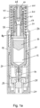
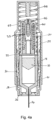
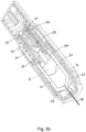
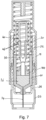
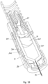
- Figure 1a shows a longitudinal cross-section of an autoinjector in accordance with a first embodiment of the invention, before administration of the drug to the patient.
- Figure 1b shows the section view of the autoinjector of Figure 1a from a different perspective.
- the autoinjector comprises a drug container 10 in which a dose of drug 12 is contained.
- a hollow hypodermic needle 14 is fixed to a front end of the drug container 10 and a plunger 16 provided within the drug container 10. Movement of the plunger 16 towards the needle 14 causes the drug to be expelled from the drug container through the needle.
- front refers to the end of the drug container or autoinjector closest to the patient in use, i.e. the end through which the drug is delivered to the patient.
- This basic syringe assembly is housed within a housing 18 that contains drive mechanisms for inserting the needle 14 into a subject and for moving the plunger 16 within the drug container 10 to expel the drug 12.
- the housing also contains a skin sensing mechanism for activating the drive mechanisms on contact with the skin of a subject and a noise generating mechanism to indicate to a user when delivery of the drug has been completed.
- the drive mechanism comprises two springs, one for inserting the needle and one for moving the plunger.
- helical springs formed from metal are used.
- other forms of spring may be used, such as gas springs or indeed any suitable mechanical drive incorporating a resilient member that can store potential energy to be subsequently released for driving the needle or plunger, and in any combination.
- the helical springs are arranged one within the other, in a coaxial relationship. However, it is not essential that they are coaxial, nor that they nest within each other, but there are advantages to both these features.
- the outer spring 20 is used for driving the drug container 10 and needle 14 forward through the housing 18 to insert the needle into a subject.
- the inner spring 22 is used to drive the plunger within the drug container to expel the drug 12 through the needle. However, in other embodiments the roles may be reversed with an inner spring driving the needle and an outer spring driving a plunger.
- Figures 1a and 1b show the autoinjector in an initial state as it is delivered to an end user.
- the autoinjector includes a needle cover 24 for safety, which must be removed prior to use of the autoinjector.
- the needle cover 24 can be simply pulled off by a user or caregiver to expose the skin sensor 26.
- Figures 2a and 2b show the autoinjector with the needle cover 24 removed.
- the skin sensor 26, which extends beyond the front end of the housing, is placed against the skin of a subject in a position where the drug is to be injected.
- Application of pressure to the body of the autoinjector towards the skin surface pushes the skin sensor 26 back relative to the autoinjector housing 18.
- the needle 14 is still covered by a front end housing 28, so the user applied pressure does not directly cause the needle 14 to be inserted through the skin. Instead the skin sensor acts as a trigger.
- the needle 14 and drug container 10 are retained relative to the front end housing 28 by needle insertion latches 30 that engage a front end of the drug container 10.
- the needle insertion latches 30 are released, as is explained in detail with reference to Figures 14 to 18 .
- the outer spring 20 pushes the drug container 10 and needle 14 forward through the housing 18 to insert the needle into the patient. This is illustrated in Figures 3a and 3b .
- the outer spring 20 is positioned between the main housing 18 and a first component 32, in this embodiment referred to as outer spring component 32.
- the outer spring component is coupled to the drug container, as can be seen more clearly in Figures 9a and 9b .
- the outer spring component 32 comprises engaging arms 34 that engage with lugs 36 formed on an outer surface of the drug container 10.
- any suitable means of engagement between the outer spring component and the drug container 10 may be used, or simply abutment of the outer spring component 32 against the drug container 10.
- the outer spring component 32 moves with the drug container 10 as the needle 14 is inserted.
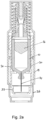
- the inner spring 22 is held between the outer spring component 32 and a second component 38, in this embodiment also referred to as an inner spring component 38.
- the inner spring component acts on the plunger during expulsion of the drug. But the outer spring component 32 retains the inner spring 22 in a compressed condition until the needle is partially or fully inserted.
- the outer spring component 32 extends around the inner spring 22, over a back side of the inner spring, and has leg portions 40 positioned within the inner spring.
- the leg potions 40 are clearly illustrated in Figure 10b .
- the inner spring component 38 comprises a front end pusher portion 44 that engages with the plunger, as will be described with reference to Figures 5a and 5b .
- the inner spring component 38 also comprises an inner retaining component in the form of inner resilient leg portions 42 that include inner spring retaining lobes 46 at their back ends.
- the inner resilient leg portions are pressed outwardly by a locking surface 48 that is part of (or rigidly fixed to) the main housing so that retaining lobes 46 engage with an inner spring retaining surface 47 on the outer spring component 32 and are prevented from disengagement by the locking surface 48.
- the inner spring is locked in a compressed state, and moves with the outer spring component 32, until the retaining lobes 46 can be released from the inner spring retaining surface 47.
- the locking surface 48 is dimensioned so that the inner resilient leg portions 42 disengage with the locking surface 48 as or just before the drug container 10 reaches the end of its travel within the main housing 18, i.e. as the outer spring reaches its fullest extension. As soon as the inner resilient leg portions 42 are disengaged from the locking surface 48, the lobes 46 disengage from the retaining surface 47. This disengagement is due to the action of the inner spring 22.
- Figures 4a and 4b show the autoinjector in a position when the inner spring 22 has been released and lobes 46 of the inner resilient leg portions 42 are pressed within the outer spring component 32.
- the front end pusher portion 44 of the inner spring component is driven towards the plunger 16.
- a seal 56 may be provided across the back end of the drug container 10 to maintain the drug in pristine condition during storage, and this seal is ruptured by the front end pusher portion 44.
- the front end pusher portion 44 then engages the plunger 16 and drives it within the drug container to expel the drug, as shown in Figures 5a and 5b .
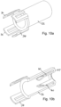
- leg portions 40 of the outer spring component are dimensioned so that at or just before the point when the plunger reaches the end of its travel, the lobes 46 on the inner spring component 42 are released from the leg portions 40. This release causes the inner resilient arms 42 to expand outwardly from their compressed state, and percussive surfaces 50 on the inner resilient arms above the lobes 46 strike the end of the leg portions 40 to generate an audible sound. This position is illustrated in Figures 6a and 6b . The sound indicates to the user that delivery of the drug is complete and that the needle can be withdrawn from the subject.
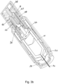
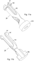
- Figure 7 illustrates the autoinjector after the drug has been expelled and the autoinjector has been removed from the patient, allowing a needle safety mechanism to extend to cover the needle.
- the materials used for the housing 18, cap 24, skin sensor 26, front end housing 28, needle insertion latches 30, outer spring component 32 and inner spring component 38 may be plastic, such as EVOH or polyamide, or metal.
- the inner surface of the drug container must be compatible with the drug and the drug container may be formed from glass or plastic.
- the various elements described as resilient must have suitable elasticity.
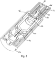
- the plunger may be a standard rubber plunger 16 or may be a cup seal plunger 52, as illustrated in Figure 8 .
- a cup seal plunger used in conjunction with a back end sealing element 56 which is ruptured by the inner spring component, provides for a more reliable and low friction engagement with the inner wall of the drug container 10.
- the cup seal plunger may be formed from a substantially non-elastomeric material such as polypropylene, polyethylene or FEP (Fluorinated Ethylene Propylene).
- the drive mechanism described with reference to Figures 1 to 11 allows for different drive members to be used for needle insertion and for drug expulsion.
- the release mechanism for the drug expulsion is provided internally of the both the drive means, i.e. the outer and inner springs 20, 22. This allows for compact springs to be used that supply an appropriate force for each stage of drug delivery, and for a compact overall device.
- the noise generating mechanism provided by the percussive surface 50 on the inner spring component striking the outer spring component 32 can be reversed or enhanced by forcing a surface on the outer spring component 32 to strike a portion of the inner spring component 38 as, or just before, drug delivery is completed.
- This can be achieved by forming legs 40 with an inwardly extending lower end 54, as shown in the Figures. When the lobes 46 pass the legs 40, the inwardly extending lower ends 54 are flexed outwardly by the lobes. The ends 54 then snap back to strike the percussive surface 50 once the lobes 46 have passed.
- the noise generating mechanism does not require the lower ends of the legs 40 to be inwardly extending; they may simply be straight, and struck by percussive surface 50 to generate a noise.
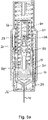
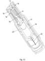
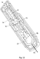
- Figures 12 and 13 show a second embodiment of an autoinjector, this second embodiment not being according to the claimed invention.
- Fig. 12 shows second embodiment of an autoinjector with a single drive spring 60 that drives both a needle 62 and a drug container 64 through a housing 66 for needle insertion and a drives a plunger 68 through the drug container 64 for expulsion of the drug.
- the drive mechanism is activated by a push button 70 that squeezes spring component 72 to release it from bearing surface 74.
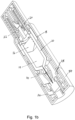
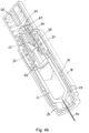
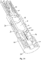
- Figures 14 to 18 illustrate more clearly the mechanism used to release the outer spring 20 of the first embodiment using the skin sensor 26.
- Figure 14 is a view of the autoinjector shown in Figure 1a from a different perspective, with the main housing 18 removed.
- Figure 14 illustrates more clearly that the skin sensor 26 extends to about midway up the drug container 10.
- the needle insertion latches 30 are resilient arms 300 on which heads 310 are provided. The heads engage the front end of the drug container 10 to retain the outer spring.
- the latches 30 may be formed as a single moulding with the front end body 24. In the position shown in Figure 14 heads 310 are held in engagement with the drug container by the skin sensor 26, including skin sensor lugs 260.
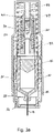
- Figure 15 is a view of the autoinjector shown in Fig. 2a from a different perspective, with the main housing 18 removed. The cap 26 has been removed.
- Figure 16 illustrates the autoinjector of Figure 15 with the skin sensor moved back as a result of contact with the skin of a patient.
- the skin sensor has cut out portions 262 that correspond to heads 310 which are moved into alignment with heads 310 in the position shown in Figure 16 .
- Figure 17 shows the autoinjector of Figure 16 a moment later.
- the space provided by cut out portions 262 allow the arms 300 to flex outwardly under the force provided by the outer spring 20 through the drug container 10.
- the heads 310 are thus moved out of engagement with the front end of the drug container and the drug container 10 can then move forward within the housing to insert the needle 14.
- Figure 18 is a view of the autoinjector shown in Fig. 3a from a different perspective, with the main housing 18 removed.
- the outer spring 20 is fully extended and the needle in an inserted position.
- the arms 300 remain flexed away from the drug container 10, and the heads remain within cut out portions 262.
- a skin sensor activation mechanism of this type which releases a front end of a drug container to activate a needle insertion mechanism may be used with an autoinjector having only a single drive means for either or both needle insertion and drug expulsion.
Landscapes
- Health & Medical Sciences (AREA)
- Vascular Medicine (AREA)
- Engineering & Computer Science (AREA)
- Anesthesiology (AREA)
- Biomedical Technology (AREA)
- Heart & Thoracic Surgery (AREA)
- Hematology (AREA)
- Life Sciences & Earth Sciences (AREA)
- Animal Behavior & Ethology (AREA)
- General Health & Medical Sciences (AREA)
- Public Health (AREA)
- Veterinary Medicine (AREA)
- Infusion, Injection, And Reservoir Apparatuses (AREA)
Applications Claiming Priority (2)
| Application Number | Priority Date | Filing Date | Title |
|---|---|---|---|
| GBGB1020475.8A GB201020475D0 (en) | 2010-12-02 | 2010-12-02 | Delivery mechanism for an autoinjector |
| PCT/GB2011/052378 WO2012073035A1 (en) | 2010-12-02 | 2011-12-01 | Delivery mechanism for an autoinjector |
Publications (2)
| Publication Number | Publication Date |
|---|---|
| EP2646086A1 EP2646086A1 (en) | 2013-10-09 |
| EP2646086B1 true EP2646086B1 (en) | 2023-03-22 |
Family
ID=43531387
Family Applications (1)
| Application Number | Title | Priority Date | Filing Date |
|---|---|---|---|
| EP11808277.5A Active EP2646086B1 (en) | 2010-12-02 | 2011-12-01 | Delivery mechanism for an autoinjector |
Country Status (6)
| Country | Link |
|---|---|
| US (1) | US10406288B2 (enExample) |
| EP (1) | EP2646086B1 (enExample) |
| JP (1) | JP5999657B2 (enExample) |
| CN (1) | CN103370091B (enExample) |
| GB (1) | GB201020475D0 (enExample) |
| WO (1) | WO2012073035A1 (enExample) |
Families Citing this family (57)
| Publication number | Priority date | Publication date | Assignee | Title |
|---|---|---|---|---|
| US8052645B2 (en) | 2008-07-23 | 2011-11-08 | Avant Medical Corp. | System and method for an injection using a syringe needle |
| US9974904B2 (en) | 2008-05-20 | 2018-05-22 | Avant Medical Corp. | Autoinjector system |
| US8177749B2 (en) | 2008-05-20 | 2012-05-15 | Avant Medical Corp. | Cassette for a hidden injection needle |
| CA3081980C (en) | 2009-10-16 | 2022-10-18 | Janssen Biotech, Inc. | Palm activated drug delivery device |
| US9233213B2 (en) | 2009-10-16 | 2016-01-12 | Janssen Biotech, Inc. | Palm activated drug delivery device |
| US9084849B2 (en) | 2011-01-26 | 2015-07-21 | Kaleo, Inc. | Medicament delivery devices for administration of a medicament within a prefilled syringe |
| HUE042822T2 (hu) | 2011-04-20 | 2019-07-29 | Amgen Inc | Automata befecskendezõ szerkezet |
| EP2572741A1 (en) | 2011-09-23 | 2013-03-27 | Sanofi-Aventis Deutschland GmbH | Medicament delivery device and actuation mechanism for a drug delivery device |
| USD898908S1 (en) | 2012-04-20 | 2020-10-13 | Amgen Inc. | Pharmaceutical product cassette for an injection device |
| US9522235B2 (en) | 2012-05-22 | 2016-12-20 | Kaleo, Inc. | Devices and methods for delivering medicaments from a multi-chamber container |
| GB201212238D0 (en) * | 2012-07-10 | 2012-08-22 | Oval Medical Technologies Ltd | Drug delivery device with stressed plunger rod |
| GB2504128A (en) * | 2012-07-20 | 2014-01-22 | Oval Medical Technologies Ltd | Automatic injector with a skin contact element |
| RU2621413C2 (ru) * | 2012-12-21 | 2017-06-05 | Кэрбей Юроп Лтд | Устройство подачи лекарственных средств |
| TWI614041B (zh) | 2013-03-15 | 2018-02-11 | 安美基公司 | 用於注射器之匣盒 |
| EA031953B1 (ru) * | 2013-03-15 | 2019-03-29 | Янссен Байотек, Инк. | Устройство для доставки лекарственных средств, приводимое в действие ладонью |
| JP6336564B2 (ja) | 2013-03-15 | 2018-06-06 | アムゲン・インコーポレーテッド | 薬物カセット、自動注入器、および自動注入器システム |
| EP2781230B2 (de) * | 2013-03-22 | 2025-05-14 | Ypsomed AG | Substanzabgabevorrichtung mit Signalvorrichtung |
| AT514484B1 (de) * | 2013-06-24 | 2015-05-15 | Pharma Consult Gmbh | Aktivator für einen Autoinjektor |
| JP6446042B2 (ja) | 2013-07-01 | 2018-12-26 | クレデンス メドシステムズ インコーポレイテッド | 安全注射器 |
| EP2823841A1 (en) | 2013-07-09 | 2015-01-14 | Sanofi-Aventis Deutschland GmbH | Autoinjector |
| GB201313782D0 (en) * | 2013-08-01 | 2013-09-18 | Oval Medical Technologies Ltd | Drug delivery device |
| RU2689762C2 (ru) * | 2013-08-29 | 2019-05-28 | Санофи-Авентис Дойчланд Гмбх | Оболочка и колпачок для устройства для инъекций, выполненные из наружной металлической части и внутренней пластиковой части |
| AU2014348292B2 (en) * | 2013-11-15 | 2019-05-23 | Credence Medsystems Inc. | System and method for drug delivery with a safety syringe |
| PL2745866T3 (pl) * | 2014-01-30 | 2017-04-28 | Tecpharma Licensing Ag | Zabezpieczenie przed uruchomieniem automatycznego iniektora |
| EP2923714A1 (en) | 2014-03-28 | 2015-09-30 | Sanofi-Aventis Deutschland GmbH | Autoinjector triggered by skin contact |
| US10010677B2 (en) | 2014-04-24 | 2018-07-03 | Credence Medsystems, Inc. | System and method for safety syringe |
| CN111840696B (zh) | 2014-06-03 | 2022-12-20 | 安姆根有限公司 | 可控制药物递送系统和使用方法 |
| EP3848072A1 (en) | 2014-12-19 | 2021-07-14 | Amgen Inc. | Drug delivery device with proximity sensor |
| US11357916B2 (en) | 2014-12-19 | 2022-06-14 | Amgen Inc. | Drug delivery device with live button or user interface field |
| WO2016154427A2 (en) | 2015-03-24 | 2016-09-29 | Kaleo, Inc. | Devices and methods for delivering a lyophilized medicament |
| US20200384209A1 (en) * | 2015-04-24 | 2020-12-10 | Shl Medical Ag | Drive mechanism |
| CN107438443B (zh) * | 2015-04-24 | 2020-09-01 | 艾斯曲尔医疗公司 | 驱动机构 |
| US10576206B2 (en) | 2015-06-30 | 2020-03-03 | Kaleo, Inc. | Auto-injectors for administration of a medicament within a prefilled syringe |
| CN109310822A (zh) | 2016-05-16 | 2019-02-05 | 艾斯曲尔医疗公司 | 注射装置 |
| US10603445B2 (en) | 2016-06-09 | 2020-03-31 | Becton, Dickinson And Company | Needle actuator assembly for drug delivery system |
| US10792432B2 (en) | 2016-06-09 | 2020-10-06 | Becton, Dickinson And Company | Drive assembly and spacer for drug delivery system |
| US10549044B2 (en) | 2016-06-09 | 2020-02-04 | Becton, Dickinson And Company | Spacer assembly for drug delivery system |
| US10773024B2 (en) * | 2016-06-09 | 2020-09-15 | Becton, Dickinson And Company | Drive assembly for drug delivery system |
| US10751476B2 (en) | 2016-06-09 | 2020-08-25 | Becton, Dickinson And Company | Actuator assembly for drug delivery system |
| WO2018060024A1 (en) * | 2016-09-27 | 2018-04-05 | Sanofi-Aventis Deutschland Gmbh | A medicament delivery device |
| GB201616709D0 (en) * | 2016-09-30 | 2016-11-16 | Owen Mumford Ltd | Injection device |
| EP3558420B1 (en) | 2016-12-23 | 2024-09-18 | Kaleo, Inc. | Medicament delivery device and methods for delivering drugs to infants and children |
| CN107308524B (zh) * | 2017-08-09 | 2019-02-15 | 甘肃成纪生物药业有限公司 | 一种快速自动注射装置 |
| EP3610907A1 (en) * | 2017-08-09 | 2020-02-19 | Gansu Changee Bio-pharmaceutical Co., Ltd. | Rapid and automatic syringe |
| EP4397336A3 (en) | 2017-10-16 | 2024-10-09 | Becton, Dickinson and Company | Spacer assembly for drug delivery device |
| US12569620B2 (en) | 2018-01-19 | 2026-03-10 | Birya Biotech, Inc. | Tool for servicing an auto-injector |
| US20200376199A1 (en) * | 2018-03-22 | 2020-12-03 | Daniel Harris Orol | Auto-injection device |
| US10835685B2 (en) * | 2018-05-30 | 2020-11-17 | Amgen Inc. | Thermal spring release mechanism for a drug delivery device |
| US20210260302A1 (en) * | 2018-08-17 | 2021-08-26 | Amgen Inc. | Activation mechanism for drug delivery device |
| EP3902584A4 (en) | 2018-12-29 | 2022-09-07 | Kaleo, Inc. | DEVICES AND METHODS FOR DELIVERING SUBSTANCES IN A PRE-FILLED SYRINGE |
| CA3145580A1 (en) | 2019-08-09 | 2021-02-18 | Kaleo, Inc. | Devices and methods for delivery of substances within a prefilled syringe |
| EP3795196B1 (de) | 2019-09-18 | 2022-05-11 | Heraeus Medical GmbH | Vorrichtung zur temporären, lokalen applikation von fluiden |
| CA3091601A1 (en) * | 2019-09-18 | 2021-03-18 | Heraeus Medical Gmbh | Device for temporarily, locally applying fluids |
| US12268847B1 (en) | 2021-02-10 | 2025-04-08 | Kaleo, Inc. | Devices and methods for delivery of substances within a medicament container |
| KR102807212B1 (ko) * | 2023-06-01 | 2025-05-16 | 주식회사 비에스엘 | 자동 약물 주입 장치 |
| KR102938216B1 (ko) | 2023-06-01 | 2026-03-12 | 주식회사 비에스엘 | 청각적 피드백 요소를 구비하는 자동 약물 주입 장치 |
| CN120860379A (zh) * | 2024-04-30 | 2025-10-31 | 贝克顿·迪金森公司 | 自动注射装置 |
Family Cites Families (19)
| Publication number | Priority date | Publication date | Assignee | Title |
|---|---|---|---|---|
| AU573369B2 (en) | 1984-07-31 | 1988-06-02 | N.J. Phillips Pty. Limited | A rumen injector |
| FR2733155B1 (fr) * | 1995-04-18 | 1997-09-19 | Tebro | Auto-injecteur rechargeable |
| SE9803662D0 (sv) | 1998-10-26 | 1998-10-26 | Pharmacia & Upjohn Ab | Autoinjector |
| GB0205066D0 (en) | 2002-03-05 | 2002-04-17 | Owen Mumford Ltd | Improvements relating to injection devices |
| WO2004047890A1 (de) * | 2002-11-25 | 2004-06-10 | Tecpharma Licensing Ag | Vorrichtung zum automatischen injizieren eines wirkstoffes |
| US7500963B2 (en) * | 2003-07-22 | 2009-03-10 | Safety Syringes, Inc. | Systems and methods for automatic medical injection with safeguard |
| DE10342059B4 (de) | 2003-09-11 | 2007-03-01 | Tecpharma Licensing Ag | Verabreichungsvorrichtung mit Einstech- und Ausschütteinrichtung |
| US20050101919A1 (en) * | 2003-11-07 | 2005-05-12 | Lennart Brunnberg | Device for an injector |
| US7449012B2 (en) * | 2004-08-06 | 2008-11-11 | Meridian Medical Technologies, Inc. | Automatic injector |
| US7918824B2 (en) * | 2005-06-21 | 2011-04-05 | Eli Lilly And Company | Needled pharmaceutical delivery device with triggered automatic needle insertion and manually controlled pharmaceutical injection |
| EP1904131A2 (en) * | 2005-06-21 | 2008-04-02 | Eli Lilly And Company | Apparatus and method for injecting a pharmaceutical |
| GB2443606B (en) | 2006-11-13 | 2011-07-20 | Cilag Gmbh Int | Injection device |
| DE102007013838A1 (de) * | 2007-03-22 | 2008-09-25 | Tecpharma Licensing Ag | Injektionsvorrichtung mit zeitkonstantem Ausschüttsignal |
| DK2162170T3 (da) * | 2007-07-06 | 2011-06-14 | Shl Group Ab | Enkeltskudsinjektionssprøjte med dobbeltfjedre |
| US8308695B2 (en) * | 2007-11-14 | 2012-11-13 | Shl Group Ab | Automatic injection device with actively triggered syringe withdrawal |
| WO2010035059A1 (en) * | 2008-09-29 | 2010-04-01 | Becton Dickinson France | Automatic injection device with audible indicator of completed injection |
| US8915886B2 (en) * | 2009-10-21 | 2014-12-23 | Owen Mumford Limited | Autoinjector |
| EP2438942A1 (en) | 2010-10-08 | 2012-04-11 | Sanofi-Aventis Deutschland GmbH | Auto-injector |
| NZ609117A (en) | 2010-10-08 | 2014-12-24 | Sanofi Aventis Deutschland | Auto-injector |
-
2010
- 2010-12-02 GB GBGB1020475.8A patent/GB201020475D0/en not_active Ceased
-
2011
- 2011-12-01 EP EP11808277.5A patent/EP2646086B1/en active Active
- 2011-12-01 CN CN201180064514.8A patent/CN103370091B/zh not_active Expired - Fee Related
- 2011-12-01 US US13/989,551 patent/US10406288B2/en active Active
- 2011-12-01 JP JP2013541429A patent/JP5999657B2/ja active Active
- 2011-12-01 WO PCT/GB2011/052378 patent/WO2012073035A1/en not_active Ceased
Also Published As
| Publication number | Publication date |
|---|---|
| JP2014500090A (ja) | 2014-01-09 |
| EP2646086A1 (en) | 2013-10-09 |
| WO2012073035A1 (en) | 2012-06-07 |
| CN103370091A (zh) | 2013-10-23 |
| US20140046259A1 (en) | 2014-02-13 |
| CN103370091B (zh) | 2016-11-09 |
| US10406288B2 (en) | 2019-09-10 |
| GB201020475D0 (en) | 2011-01-19 |
| JP5999657B2 (ja) | 2016-09-28 |
Similar Documents
| Publication | Publication Date | Title |
|---|---|---|
| EP2646086B1 (en) | Delivery mechanism for an autoinjector | |
| EP3125975B1 (en) | Autoinjector having needle shield triggering | |
| CN103328024B (zh) | 用于自动注射器的驱动组件以及组装自动注射器的方法 | |
| EP2605814B1 (en) | Medical auto-injection device for manual needle insertion having needle shield, damping mechanism and audible and tactile feedback | |
| EP3027247B1 (en) | Drug delivery device | |
| JP5905462B2 (ja) | 医療用注射器具 | |
| JP6100840B2 (ja) | 注射装置 | |
| CN104853787B (zh) | 自动药物输送装置 | |
| ES2862474T3 (es) | Inyector automático para inyección de epinefrina | |
| CN101912648B (zh) | 用于注射所分配剂量的液体药物的设备 | |
| EP3875130B1 (en) | Autoinjector with retracting needle | |
| US20210128836A1 (en) | Power unit for use in an autoinjector and method of assembling such power unit | |
| JP2020505202A (ja) | 自動注射器デバイス | |
| EP3240594B1 (en) | Drug delivery device with a hydraulic trigger mechanism | |
| GB2606984A (en) | Injection device | |
| GB2504128A (en) | Automatic injector with a skin contact element | |
| GB2603494A (en) | Injection device | |
| HK1110811B (en) | Medicine injection devices and methods | |
| HK1110811A1 (en) | Medicine injection devices and methods |
Legal Events
| Date | Code | Title | Description |
|---|---|---|---|
| PUAI | Public reference made under article 153(3) epc to a published international application that has entered the european phase |
Free format text: ORIGINAL CODE: 0009012 |
|
| 17P | Request for examination filed |
Effective date: 20130611 |
|
| AK | Designated contracting states |
Kind code of ref document: A1 Designated state(s): AL AT BE BG CH CY CZ DE DK EE ES FI FR GB GR HR HU IE IS IT LI LT LU LV MC MK MT NL NO PL PT RO RS SE SI SK SM TR |
|
| DAX | Request for extension of the european patent (deleted) | ||
| STAA | Information on the status of an ep patent application or granted ep patent |
Free format text: STATUS: EXAMINATION IS IN PROGRESS |
|
| 17Q | First examination report despatched |
Effective date: 20161027 |
|
| RAP1 | Party data changed (applicant data changed or rights of an application transferred) |
Owner name: OVAL MEDICAL TECHNOLOGIES LIMITED |
|
| GRAP | Despatch of communication of intention to grant a patent |
Free format text: ORIGINAL CODE: EPIDOSNIGR1 |
|
| STAA | Information on the status of an ep patent application or granted ep patent |
Free format text: STATUS: GRANT OF PATENT IS INTENDED |
|
| INTG | Intention to grant announced |
Effective date: 20221012 |
|
| GRAS | Grant fee paid |
Free format text: ORIGINAL CODE: EPIDOSNIGR3 |
|
| GRAA | (expected) grant |
Free format text: ORIGINAL CODE: 0009210 |
|
| STAA | Information on the status of an ep patent application or granted ep patent |
Free format text: STATUS: THE PATENT HAS BEEN GRANTED |
|
| AK | Designated contracting states |
Kind code of ref document: B1 Designated state(s): AL AT BE BG CH CY CZ DE DK EE ES FI FR GB GR HR HU IE IS IT LI LT LU LV MC MK MT NL NO PL PT RO RS SE SI SK SM TR |
|
| REG | Reference to a national code |
Ref country code: GB Ref legal event code: FG4D |
|
| REG | Reference to a national code |
Ref country code: CH Ref legal event code: EP |
|
| REG | Reference to a national code |
Ref country code: IE Ref legal event code: FG4D |
|
| REG | Reference to a national code |
Ref country code: DE Ref legal event code: R096 Ref document number: 602011073740 Country of ref document: DE |
|
| REG | Reference to a national code |
Ref country code: AT Ref legal event code: REF Ref document number: 1554910 Country of ref document: AT Kind code of ref document: T Effective date: 20230415 |
|
| REG | Reference to a national code |
Ref country code: LT Ref legal event code: MG9D |
|
| P01 | Opt-out of the competence of the unified patent court (upc) registered |
Effective date: 20230530 |
|
| REG | Reference to a national code |
Ref country code: NL Ref legal event code: MP Effective date: 20230322 |
|
| PG25 | Lapsed in a contracting state [announced via postgrant information from national office to epo] |
Ref country code: RS Free format text: LAPSE BECAUSE OF FAILURE TO SUBMIT A TRANSLATION OF THE DESCRIPTION OR TO PAY THE FEE WITHIN THE PRESCRIBED TIME-LIMIT Effective date: 20230322 Ref country code: NO Free format text: LAPSE BECAUSE OF FAILURE TO SUBMIT A TRANSLATION OF THE DESCRIPTION OR TO PAY THE FEE WITHIN THE PRESCRIBED TIME-LIMIT Effective date: 20230622 Ref country code: LV Free format text: LAPSE BECAUSE OF FAILURE TO SUBMIT A TRANSLATION OF THE DESCRIPTION OR TO PAY THE FEE WITHIN THE PRESCRIBED TIME-LIMIT Effective date: 20230322 Ref country code: LT Free format text: LAPSE BECAUSE OF FAILURE TO SUBMIT A TRANSLATION OF THE DESCRIPTION OR TO PAY THE FEE WITHIN THE PRESCRIBED TIME-LIMIT Effective date: 20230322 Ref country code: HR Free format text: LAPSE BECAUSE OF FAILURE TO SUBMIT A TRANSLATION OF THE DESCRIPTION OR TO PAY THE FEE WITHIN THE PRESCRIBED TIME-LIMIT Effective date: 20230322 |
|
| REG | Reference to a national code |
Ref country code: AT Ref legal event code: MK05 Ref document number: 1554910 Country of ref document: AT Kind code of ref document: T Effective date: 20230322 |
|
| PG25 | Lapsed in a contracting state [announced via postgrant information from national office to epo] |
Ref country code: SE Free format text: LAPSE BECAUSE OF FAILURE TO SUBMIT A TRANSLATION OF THE DESCRIPTION OR TO PAY THE FEE WITHIN THE PRESCRIBED TIME-LIMIT Effective date: 20230322 Ref country code: NL Free format text: LAPSE BECAUSE OF FAILURE TO SUBMIT A TRANSLATION OF THE DESCRIPTION OR TO PAY THE FEE WITHIN THE PRESCRIBED TIME-LIMIT Effective date: 20230322 Ref country code: GR Free format text: LAPSE BECAUSE OF FAILURE TO SUBMIT A TRANSLATION OF THE DESCRIPTION OR TO PAY THE FEE WITHIN THE PRESCRIBED TIME-LIMIT Effective date: 20230623 Ref country code: FI Free format text: LAPSE BECAUSE OF FAILURE TO SUBMIT A TRANSLATION OF THE DESCRIPTION OR TO PAY THE FEE WITHIN THE PRESCRIBED TIME-LIMIT Effective date: 20230322 |
|
| PG25 | Lapsed in a contracting state [announced via postgrant information from national office to epo] |
Ref country code: SM Free format text: LAPSE BECAUSE OF FAILURE TO SUBMIT A TRANSLATION OF THE DESCRIPTION OR TO PAY THE FEE WITHIN THE PRESCRIBED TIME-LIMIT Effective date: 20230322 Ref country code: RO Free format text: LAPSE BECAUSE OF FAILURE TO SUBMIT A TRANSLATION OF THE DESCRIPTION OR TO PAY THE FEE WITHIN THE PRESCRIBED TIME-LIMIT Effective date: 20230322 Ref country code: PT Free format text: LAPSE BECAUSE OF FAILURE TO SUBMIT A TRANSLATION OF THE DESCRIPTION OR TO PAY THE FEE WITHIN THE PRESCRIBED TIME-LIMIT Effective date: 20230724 Ref country code: ES Free format text: LAPSE BECAUSE OF FAILURE TO SUBMIT A TRANSLATION OF THE DESCRIPTION OR TO PAY THE FEE WITHIN THE PRESCRIBED TIME-LIMIT Effective date: 20230322 Ref country code: EE Free format text: LAPSE BECAUSE OF FAILURE TO SUBMIT A TRANSLATION OF THE DESCRIPTION OR TO PAY THE FEE WITHIN THE PRESCRIBED TIME-LIMIT Effective date: 20230322 Ref country code: AT Free format text: LAPSE BECAUSE OF FAILURE TO SUBMIT A TRANSLATION OF THE DESCRIPTION OR TO PAY THE FEE WITHIN THE PRESCRIBED TIME-LIMIT Effective date: 20230322 |
|
| PG25 | Lapsed in a contracting state [announced via postgrant information from national office to epo] |
Ref country code: SK Free format text: LAPSE BECAUSE OF FAILURE TO SUBMIT A TRANSLATION OF THE DESCRIPTION OR TO PAY THE FEE WITHIN THE PRESCRIBED TIME-LIMIT Effective date: 20230322 Ref country code: PL Free format text: LAPSE BECAUSE OF FAILURE TO SUBMIT A TRANSLATION OF THE DESCRIPTION OR TO PAY THE FEE WITHIN THE PRESCRIBED TIME-LIMIT Effective date: 20230322 Ref country code: IS Free format text: LAPSE BECAUSE OF FAILURE TO SUBMIT A TRANSLATION OF THE DESCRIPTION OR TO PAY THE FEE WITHIN THE PRESCRIBED TIME-LIMIT Effective date: 20230722 |
|
| REG | Reference to a national code |
Ref country code: DE Ref legal event code: R097 Ref document number: 602011073740 Country of ref document: DE |
|
| PLBE | No opposition filed within time limit |
Free format text: ORIGINAL CODE: 0009261 |
|
| STAA | Information on the status of an ep patent application or granted ep patent |
Free format text: STATUS: NO OPPOSITION FILED WITHIN TIME LIMIT |
|
| PG25 | Lapsed in a contracting state [announced via postgrant information from national office to epo] |
Ref country code: SI Free format text: LAPSE BECAUSE OF FAILURE TO SUBMIT A TRANSLATION OF THE DESCRIPTION OR TO PAY THE FEE WITHIN THE PRESCRIBED TIME-LIMIT Effective date: 20230322 Ref country code: DK Free format text: LAPSE BECAUSE OF FAILURE TO SUBMIT A TRANSLATION OF THE DESCRIPTION OR TO PAY THE FEE WITHIN THE PRESCRIBED TIME-LIMIT Effective date: 20230322 Ref country code: CZ Free format text: LAPSE BECAUSE OF FAILURE TO SUBMIT A TRANSLATION OF THE DESCRIPTION OR TO PAY THE FEE WITHIN THE PRESCRIBED TIME-LIMIT Effective date: 20230322 |
|
| 26N | No opposition filed |
Effective date: 20240102 |
|
| PG25 | Lapsed in a contracting state [announced via postgrant information from national office to epo] |
Ref country code: IT Free format text: LAPSE BECAUSE OF FAILURE TO SUBMIT A TRANSLATION OF THE DESCRIPTION OR TO PAY THE FEE WITHIN THE PRESCRIBED TIME-LIMIT Effective date: 20230322 |
|
| REG | Reference to a national code |
Ref country code: CH Ref legal event code: PL |
|
| PG25 | Lapsed in a contracting state [announced via postgrant information from national office to epo] |
Ref country code: LU Free format text: LAPSE BECAUSE OF NON-PAYMENT OF DUE FEES Effective date: 20231201 |
|
| PG25 | Lapsed in a contracting state [announced via postgrant information from national office to epo] |
Ref country code: MC Free format text: LAPSE BECAUSE OF FAILURE TO SUBMIT A TRANSLATION OF THE DESCRIPTION OR TO PAY THE FEE WITHIN THE PRESCRIBED TIME-LIMIT Effective date: 20230322 |
|
| REG | Reference to a national code |
Ref country code: BE Ref legal event code: MM Effective date: 20231231 |
|
| PG25 | Lapsed in a contracting state [announced via postgrant information from national office to epo] |
Ref country code: MC Free format text: LAPSE BECAUSE OF FAILURE TO SUBMIT A TRANSLATION OF THE DESCRIPTION OR TO PAY THE FEE WITHIN THE PRESCRIBED TIME-LIMIT Effective date: 20230322 Ref country code: LU Free format text: LAPSE BECAUSE OF NON-PAYMENT OF DUE FEES Effective date: 20231201 |
|
| REG | Reference to a national code |
Ref country code: IE Ref legal event code: MM4A |
|
| PG25 | Lapsed in a contracting state [announced via postgrant information from national office to epo] |
Ref country code: IE Free format text: LAPSE BECAUSE OF NON-PAYMENT OF DUE FEES Effective date: 20231201 |
|
| PG25 | Lapsed in a contracting state [announced via postgrant information from national office to epo] |
Ref country code: BE Free format text: LAPSE BECAUSE OF NON-PAYMENT OF DUE FEES Effective date: 20231231 |
|
| PG25 | Lapsed in a contracting state [announced via postgrant information from national office to epo] |
Ref country code: CH Free format text: LAPSE BECAUSE OF NON-PAYMENT OF DUE FEES Effective date: 20231231 |
|
| PG25 | Lapsed in a contracting state [announced via postgrant information from national office to epo] |
Ref country code: IE Free format text: LAPSE BECAUSE OF NON-PAYMENT OF DUE FEES Effective date: 20231201 Ref country code: CH Free format text: LAPSE BECAUSE OF NON-PAYMENT OF DUE FEES Effective date: 20231231 Ref country code: BE Free format text: LAPSE BECAUSE OF NON-PAYMENT OF DUE FEES Effective date: 20231231 |
|
| PG25 | Lapsed in a contracting state [announced via postgrant information from national office to epo] |
Ref country code: BG Free format text: LAPSE BECAUSE OF FAILURE TO SUBMIT A TRANSLATION OF THE DESCRIPTION OR TO PAY THE FEE WITHIN THE PRESCRIBED TIME-LIMIT Effective date: 20230322 |
|
| PG25 | Lapsed in a contracting state [announced via postgrant information from national office to epo] |
Ref country code: BG Free format text: LAPSE BECAUSE OF FAILURE TO SUBMIT A TRANSLATION OF THE DESCRIPTION OR TO PAY THE FEE WITHIN THE PRESCRIBED TIME-LIMIT Effective date: 20230322 |
|
| PG25 | Lapsed in a contracting state [announced via postgrant information from national office to epo] |
Ref country code: CY Free format text: LAPSE BECAUSE OF FAILURE TO SUBMIT A TRANSLATION OF THE DESCRIPTION OR TO PAY THE FEE WITHIN THE PRESCRIBED TIME-LIMIT; INVALID AB INITIO Effective date: 20111201 |
|
| PG25 | Lapsed in a contracting state [announced via postgrant information from national office to epo] |
Ref country code: HU Free format text: LAPSE BECAUSE OF FAILURE TO SUBMIT A TRANSLATION OF THE DESCRIPTION OR TO PAY THE FEE WITHIN THE PRESCRIBED TIME-LIMIT; INVALID AB INITIO Effective date: 20111201 |
|
| PG25 | Lapsed in a contracting state [announced via postgrant information from national office to epo] |
Ref country code: TR Free format text: LAPSE BECAUSE OF FAILURE TO SUBMIT A TRANSLATION OF THE DESCRIPTION OR TO PAY THE FEE WITHIN THE PRESCRIBED TIME-LIMIT Effective date: 20230322 |
|
| PGFP | Annual fee paid to national office [announced via postgrant information from national office to epo] |
Ref country code: GB Payment date: 20251219 Year of fee payment: 15 |
|
| PGFP | Annual fee paid to national office [announced via postgrant information from national office to epo] |
Ref country code: FR Payment date: 20251223 Year of fee payment: 15 |
|
| PGFP | Annual fee paid to national office [announced via postgrant information from national office to epo] |
Ref country code: DE Payment date: 20251229 Year of fee payment: 15 |