EP2646064B1 - Verfahren und vorrichtungen zur ultraviolettüberwachung - Google Patents
Verfahren und vorrichtungen zur ultraviolettüberwachung Download PDFInfo
- Publication number
- EP2646064B1 EP2646064B1 EP11846235.7A EP11846235A EP2646064B1 EP 2646064 B1 EP2646064 B1 EP 2646064B1 EP 11846235 A EP11846235 A EP 11846235A EP 2646064 B1 EP2646064 B1 EP 2646064B1
- Authority
- EP
- European Patent Office
- Prior art keywords
- controller
- light source
- ultraviolet light
- intensity
- time
- Prior art date
- Legal status (The legal status is an assumption and is not a legal conclusion. Google has not performed a legal analysis and makes no representation as to the accuracy of the status listed.)
- Active
Links
Images

Classifications
-
- A—HUMAN NECESSITIES
- A61—MEDICAL OR VETERINARY SCIENCE; HYGIENE
- A61L—METHODS OR APPARATUS FOR STERILISING MATERIALS OR OBJECTS IN GENERAL; DISINFECTION, STERILISATION OR DEODORISATION OF AIR; CHEMICAL ASPECTS OF BANDAGES, DRESSINGS, ABSORBENT PADS OR SURGICAL ARTICLES; MATERIALS FOR BANDAGES, DRESSINGS, ABSORBENT PADS OR SURGICAL ARTICLES
- A61L2/00—Disinfection or sterilisation of materials or objects, in general; Accessories therefor
- A61L2/02—Disinfection or sterilisation of materials or objects, in general; Accessories therefor using physical processes
- A61L2/08—Radiation
- A61L2/10—Ultraviolet [UV] radiation
-
- A—HUMAN NECESSITIES
- A61—MEDICAL OR VETERINARY SCIENCE; HYGIENE
- A61L—METHODS OR APPARATUS FOR STERILISING MATERIALS OR OBJECTS IN GENERAL; DISINFECTION, STERILISATION OR DEODORISATION OF AIR; CHEMICAL ASPECTS OF BANDAGES, DRESSINGS, ABSORBENT PADS OR SURGICAL ARTICLES; MATERIALS FOR BANDAGES, DRESSINGS, ABSORBENT PADS OR SURGICAL ARTICLES
- A61L9/00—Disinfection, sterilisation or deodorisation of air
- A61L9/16—Disinfection, sterilisation or deodorisation of air using physical phenomena
- A61L9/18—Radiation
-
- G—PHYSICS
- G01—MEASURING; TESTING
- G01J—MEASUREMENT OF INTENSITY, VELOCITY, SPECTRAL CONTENT, POLARISATION, PHASE OR PULSE CHARACTERISTICS OF INFRARED, VISIBLE OR ULTRAVIOLET LIGHT; COLORIMETRY; RADIATION PYROMETRY
- G01J1/00—Photometry, e.g. photographic exposure meter
- G01J1/42—Photometry, e.g. photographic exposure meter using electric radiation detectors
- G01J1/429—Photometry, e.g. photographic exposure meter using electric radiation detectors applied to measurement of ultraviolet light
-
- A—HUMAN NECESSITIES
- A61—MEDICAL OR VETERINARY SCIENCE; HYGIENE
- A61L—METHODS OR APPARATUS FOR STERILISING MATERIALS OR OBJECTS IN GENERAL; DISINFECTION, STERILISATION OR DEODORISATION OF AIR; CHEMICAL ASPECTS OF BANDAGES, DRESSINGS, ABSORBENT PADS OR SURGICAL ARTICLES; MATERIALS FOR BANDAGES, DRESSINGS, ABSORBENT PADS OR SURGICAL ARTICLES
- A61L9/00—Disinfection, sterilisation or deodorisation of air
- A61L9/16—Disinfection, sterilisation or deodorisation of air using physical phenomena
- A61L9/18—Radiation
- A61L9/20—Ultraviolet radiation
-
- B—PERFORMING OPERATIONS; TRANSPORTING
- B01—PHYSICAL OR CHEMICAL PROCESSES OR APPARATUS IN GENERAL
- B01D—SEPARATION
- B01D41/00—Regeneration of the filtering material or filter elements outside the filter for liquid or gaseous fluids
-
- B—PERFORMING OPERATIONS; TRANSPORTING
- B01—PHYSICAL OR CHEMICAL PROCESSES OR APPARATUS IN GENERAL
- B01D—SEPARATION
- B01D45/00—Separating dispersed particles from gases or vapours by gravity, inertia, or centrifugal forces
-
- B—PERFORMING OPERATIONS; TRANSPORTING
- B01—PHYSICAL OR CHEMICAL PROCESSES OR APPARATUS IN GENERAL
- B01D—SEPARATION
- B01D45/00—Separating dispersed particles from gases or vapours by gravity, inertia, or centrifugal forces
- B01D45/18—Cleaning-out devices
-
- B—PERFORMING OPERATIONS; TRANSPORTING
- B01—PHYSICAL OR CHEMICAL PROCESSES OR APPARATUS IN GENERAL
- B01D—SEPARATION
- B01D46/00—Filters or filtering processes specially modified for separating dispersed particles from gases or vapours
-
- B—PERFORMING OPERATIONS; TRANSPORTING
- B01—PHYSICAL OR CHEMICAL PROCESSES OR APPARATUS IN GENERAL
- B01D—SEPARATION
- B01D47/00—Separating dispersed particles from gases, air or vapours by liquid as separating agent
-
- B—PERFORMING OPERATIONS; TRANSPORTING
- B01—PHYSICAL OR CHEMICAL PROCESSES OR APPARATUS IN GENERAL
- B01D—SEPARATION
- B01D53/00—Separation of gases or vapours; Recovering vapours of volatile solvents from gases; Chemical or biological purification of waste gases, e.g. engine exhaust gases, smoke, fumes, flue gases, aerosols
- B01D53/007—Separation of gases or vapours; Recovering vapours of volatile solvents from gases; Chemical or biological purification of waste gases, e.g. engine exhaust gases, smoke, fumes, flue gases, aerosols by irradiation
-
- F—MECHANICAL ENGINEERING; LIGHTING; HEATING; WEAPONS; BLASTING
- F24—HEATING; RANGES; VENTILATING
- F24C—DOMESTIC STOVES OR RANGES ; DETAILS OF DOMESTIC STOVES OR RANGES, OF GENERAL APPLICATION
- F24C15/00—Details
- F24C15/20—Removing cooking fumes
- F24C15/2021—Arrangement or mounting of control or safety systems
-
- G—PHYSICS
- G01—MEASURING; TESTING
- G01N—INVESTIGATING OR ANALYSING MATERIALS BY DETERMINING THEIR CHEMICAL OR PHYSICAL PROPERTIES
- G01N21/00—Investigating or analysing materials by the use of optical means, i.e. using sub-millimetre waves, infrared, visible or ultraviolet light
-
- G—PHYSICS
- G01—MEASURING; TESTING
- G01N—INVESTIGATING OR ANALYSING MATERIALS BY DETERMINING THEIR CHEMICAL OR PHYSICAL PROPERTIES
- G01N21/00—Investigating or analysing materials by the use of optical means, i.e. using sub-millimetre waves, infrared, visible or ultraviolet light
- G01N21/17—Systems in which incident light is modified in accordance with the properties of the material investigated
- G01N21/25—Colour; Spectral properties, i.e. comparison of effect of material on the light at two or more different wavelengths or wavelength bands
- G01N21/31—Investigating relative effect of material at wavelengths characteristic of specific elements or molecules, e.g. atomic absorption spectrometry
- G01N21/33—Investigating relative effect of material at wavelengths characteristic of specific elements or molecules, e.g. atomic absorption spectrometry using ultraviolet light
-
- G—PHYSICS
- G01—MEASURING; TESTING
- G01N—INVESTIGATING OR ANALYSING MATERIALS BY DETERMINING THEIR CHEMICAL OR PHYSICAL PROPERTIES
- G01N21/00—Investigating or analysing materials by the use of optical means, i.e. using sub-millimetre waves, infrared, visible or ultraviolet light
- G01N21/17—Systems in which incident light is modified in accordance with the properties of the material investigated
- G01N21/47—Scattering, i.e. diffuse reflection
- G01N21/49—Scattering, i.e. diffuse reflection within a body or fluid
- G01N21/51—Scattering, i.e. diffuse reflection within a body or fluid inside a container, e.g. in an ampoule
-
- A—HUMAN NECESSITIES
- A61—MEDICAL OR VETERINARY SCIENCE; HYGIENE
- A61L—METHODS OR APPARATUS FOR STERILISING MATERIALS OR OBJECTS IN GENERAL; DISINFECTION, STERILISATION OR DEODORISATION OF AIR; CHEMICAL ASPECTS OF BANDAGES, DRESSINGS, ABSORBENT PADS OR SURGICAL ARTICLES; MATERIALS FOR BANDAGES, DRESSINGS, ABSORBENT PADS OR SURGICAL ARTICLES
- A61L2209/00—Aspects relating to disinfection, sterilisation or deodorisation of air
- A61L2209/10—Apparatus features
- A61L2209/11—Apparatus for controlling air treatment
- A61L2209/111—Sensor means, e.g. motion, brightness, scent, contaminant sensors
-
- B—PERFORMING OPERATIONS; TRANSPORTING
- B01—PHYSICAL OR CHEMICAL PROCESSES OR APPARATUS IN GENERAL
- B01D—SEPARATION
- B01D2259/00—Type of treatment
- B01D2259/45—Gas separation or purification devices adapted for specific applications
- B01D2259/4508—Gas separation or purification devices adapted for specific applications for cleaning air in buildings
-
- B—PERFORMING OPERATIONS; TRANSPORTING
- B01—PHYSICAL OR CHEMICAL PROCESSES OR APPARATUS IN GENERAL
- B01D—SEPARATION
- B01D2259/00—Type of treatment
- B01D2259/80—Employing electric, magnetic, electromagnetic or wave energy, or particle radiation
- B01D2259/804—UV light
Definitions
- the present invention is directed to maintenance of filtering systems that use ultraviolet light to degrade or sterilized contaminants.
- United States patent application US 2010/0044319 A1 describes a controller for a UV purification system having UV lamps including a sensor in communication with a given UV lamp as well as processor in communication with the sensor.
- the sensor provides the UV light intensity rate of the UV lamp (sensed rate) and transmits this information to the processor which compares the sensed rate with a memory stored desired UV light intensity rate (desired rate).
- An indicator in communication with the processor indicates when the UV lamp is producing a UV light intensity below the desired rate.
- a method of maintaining a ventilation treatment device according to the present invention is set out according to appended claim 1.
- a ventilation treatment device according to the present invention is set out according to appended claim 5.
- Embodiments of the invention are set out according to the appended dependent claims.
- Described herein is a control system for a UV air treatment system, especially one used for cleaning a fume stream such as in a kitchen exhaust system which detects a need for cleaning maintenance on the UV light source based on changes in light intensity.
- the system further detects the light intensity each time the UV light source is cleaned to determine if the drop in intensity after cleaning indicates that the UV light source should be replaced.
- the cleaning and replacement requirements are indicated automatically by a user interface.
- UV sources such as lamp bulbs tend to get dirty.
- oil droplets appear in grease smoke from kitchen, such as a commercial kitchen.
- Grease filters are not entirely effective to remove grease droplet making up the majority of the pollutants in such smoke because they only capture the larger droplets. UV can be used to degrade much finer droplets making up grease smoke.
- UV lamps must be exposed to grease smoke. However, even fine particles tend to stick to surfaces of the UV lamps reducing their output.
- the present invention is an intelligent detection and maintenance advisor device that monitors the intensity of UV sources over time and indicates to maintenance operators when to clean UV sources that have become dirty and when to replace the sources based on a historical record of the detected intensity.
- a ventilation treatment device 104 receives polluted air 118.
- the polluted air flows through the ventilation treatment device 104 where the polluted air 118 is exposed to light from a UV source 10.
- the treated air 120 then exits the ventilation treatment device 104.
- a sensor 102 continually monitors the intensity of light from the UV source 10 by detecting some of the light 112 that passes to the sensor 102.
- the sensor 102 may be protected from contamination by a flush stream of clean air 116 forced by a fan 114 into the ventilation treatment device 104, thereby preventing pollutants in the ventilation treatment device 104 from accumulating on the sensor 102.
- a controller 100 regularly polls the sensor 102 and creates a record, which is stored in a non-volatile memory 108 (e.g., a flash memory), of readings from the sensor 102.
- a non-volatile memory 108 e.g., a flash memory
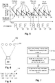
- a (sawtooth-shaped) curve 40 shows a history of the light intensity indicated by the sensor 102 according to axes of intensity versus time.
- a new UV source 10 generates an output as indicated at 1. When light from the UV source falls below a threshold intensity 39, as indicated by point 11, an indication is generated by the controller 100 to clean the UV source 10.
- the new UV source may be the result of a change of an expired UV source or more than one expired UV source.
- the indication is output on a user interface 106, for example, an LCD display or a lamp labeled "Clean.”
- the comparison between a stored threshold level and the detected level is made by the controller 100.
- the threshold level may be obtained upon replacement of the UV source 10 from a percentage calculation made by the controller, for example the threshold may be 50% of the intensity of the new UV source 10.
- the cleaning of the UV source 10 results in a higher intensity as indicated at 2, but the intensity is lower than the intensity 1 of a new lamp as indicated.
- the cleaned UV source 10 As the cleaned UV source 10 is used its intensity falls again to the threshold level 39 as indicated at 12 whereupon the signal to clean is again generated as indicated at 22.
- the cycle repeats with an indication to clean being output at 23 and 24 corresponding to intensity points 14 and 15.
- the corresponding clean intensity levels, 3, 4, and 5 progressively diminish with time.
- an indication 26 to replace the UV source is output at which time the intensity is restored to the level at point 6.
- 1 the time between intensity threshold crossings may diminish progressively as well providing an alternative indicator of the need to replace the UV source.
- the indication to clean may be determined by the intensity of the most recent new cycle, for example the percentage difference between the stored intensity value 2 and threshold intensity 39. If the difference exceeds a predetermined amount, the controller 100 generates a signal to clean. If it is below this predetermined level the indication to replace the UV source, e.g., a bulb, is generated. The cycle then repeats through commands 26, 27, 28 and so on coinciding with dirty points 18, 18, 19 to restore output to levels at clean points 7, 8, and 9. It should be clear that this profile can be repeated indefinitely.
- the predetermined intensity values may be stored in the nonvolatile storage 108. Other data than the intensity values can be stored. For example, the elapsed time since a cleaning indication may be stored.
- the system waits for an indication that the maintenance operation has been performed.
- a command is input by a user through the user interface to reset the maintenance indication currently being output (clean or replace).
- the system may detect the change in intensity and reset itself.
- an upper threshold may be defined which, when exceeded, indicates the UV source has been properly cleaned.
- Another upper threshold, higher than the other, is defined indicating the UV source has been properly replaced.
- the system may update the status of the UV source to a cleaned or replaced UV source.
- the controller could be configured to reset the status of the UV source if a positive change in the intensity of greater than a predefined amount is detected. So rather than having a particular threshold intensity that the light source exceeds, the reset is indicated when the positive change in intensity since a last recorded intensity is greater than a predefined amount.
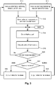
- a flow chart shows a procedure for outputting maintenance steps of cleaning and replacing UV light sources.
- Light output from a UV source is detected during normal operation of the ventilation system at S14.
- S18 from the current level of the light output measured or from an historical trend the need for either a cleaning operation or a replacement operation may be determined according to any of the criteria described elsewhere in the present specification.
- S20 if a maintenance output is indicated, control proceeds to S22 otherwise it loops back to S14.
- the type of control output may be determined and the corresponding output is generated at S24 or S25, respectively after which control proceeds to S10 or S11, respectively as indicated.
- the completion of the respective maintenance action is detected, or a command received indicating its completion, and an indication stored at S12 that the maintenance is done.
- the S12 operation may include storing a value of the intensity after a cleaning, or other data responsive thereto, for purposes of determining whether a replacement operation is, or will be, required according to criteria of any of the applicable embodiments described herein.
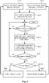
- a flow chart shows a further procedure for outputting maintenance steps of cleaning and replacing UV light sources, as an example only.
- the controller determines whether the elapsed time since a prior lamp check is beyond predefined interval TC at S214. If not the control loops, otherwise at S216, a procedure is performed in which the light output from each lamp of multiple lamps is performed to acquire the output of each lamp. At S218, the status of each lamp is determined according to criteria discussed in the present specification. If maintenance output indicator is required as determined at S220, control proceeds to S222 otherwise it loops back to S214. At S222, the type of control output is determined and the corresponding output is generated at S224 or S225, respectively after which control proceeds to S210 or S211, respectively as indicated.
- the completion of the respective maintenance action is detected, or a command received indicating its completion, and an indication stored at S212 that the maintenance is done.
- the S212 operation may include storing a value of the intensity after a cleaning, or other data responsive thereto, for purposes of determining whether a replacement operation is, or will be, required according to criteria of any of the applicable embodiments described herein.
- the system may allow operation of the lamp if a cleaning operation is required, except that the output of the user interface may continue to indicate a need for cleaning.
- the system may also prevent operation of the hood if there is no response after an output of a cleaning indication.
- the system may provide a grace period of a predefined period of time or a predefined number of startups of the ventilation system after the first output of an indication to clean or replace. The grace period may be different for each of the indications, namely clean or replace.
- the system provides a warning indication of a need for clean or replace after passing a first threshold intensity 51 but only begin enforcing the maintenance operation by preventing the use of the ventilation system after the intensity drops through a second, lower threshold 52.
- each lamp 400 in an array 402 is imaged simultaneously or individually by an imaging device such as a camera.
- the intensity of each lamp can be acquired separately by processing the image and segmenting the light intensity of each lamp 400 respectively.
- the status (here indicated as a predicted time till next required action) of each lamp can be listed on an output as a separate indication.
- a schematic of Fig. 8 can be generated by a UI with predicted hours till next cleaning or predicted hours to replacement indicated for each lamp 400 as indicated at 408.
- the data for the predicted time till indicated action can be listed in a data packet transmitted to a central controller as discussed above.
- the control system can generate a prediction of when the lamps will next need to be cleaned and when they will next need to be replaced.
- Such a system may provide an output indication of both pieces of information.
- This information may be output as a control signal to a central ventilation monitoring system so that the controller for the UV treated system does not need to have its own output display or other output terminal.
- An Internet-connected control system can automatically order a set of replacement sources when a predefined time is indicated between the current time and the predicted time for replacement.
- This feature may be implemented by providing the controller and software that runs on a general purpose computer ( Fig. 1 , 107) or one that is connected to a general control system ( Fig. 1 , GPCS 101). The latter may be a part of, for example, a control system for a commercial kitchen or the HVAC system for a building and may use a standard protocol to output status information and/or recommended actions to the general purpose control system.
- the status of the UV light source may be inferred from other detected data.
- the surface pattern of light of a lamp may be compared in terms of uniformity or in terms of a particular pattern of intensity over its surface such that the light distribution, rather than the overall intensity indicates the condition of the lamp.
- an irregular pattern of light or one or light blocking "blobs" may be imaged by a suitable camera to indicate fouling by fumes or aerosols in the ventilation air, for example.
- the control system may be configured to detect other anomalies in the output of the UV light source.
- the decay rate of intensity of the UV source may provide a useful indicator of the operating status of a filter (indicated at 127 in Fig. 1 ) upstream of the UV sources.
- a filter indicated at 127 in Fig. 1
- typically grease filters are used to trap particulates before further treatment by a UV source. If the grease filters are left out, not properly installed, or functioning poorly, the rate of fouling of the UV source may indicate this. This attending abnormally high rate of diminution of intensity may be indicated in any of the described systems according to any of the information output schemed described above or elsewhere.
- the failure of a lamp or power supply may be detected and indicated by any of the disclosed UI systems as well as diagnosis of performance and maintenance actions as discussed.
- a ventilation system is started after UV sources that were just replaced.
- the ventilation system is operated continuously or in multiple cycles (such as multiple mealtime cycles of operation of a kitchen or diurnal cycles of an office ventilation system).
- the UV source intensity is acquired (or otherwise acquired for example, the light sources may be imaged according to the respective example).
- the UV source or each element e.g., lamp
- the intensity data may be stored in original for and used at any selected time to generate a prediction or "action required" output such as an indication to clean or an indication to replace one lamp or a single UV source.
- a prediction or "action required" output such as an indication to clean or an indication to replace one lamp or a single UV source.
- the elapsed time may be calculated and output.
- a succession of status indications may be generated responsively to a request or automatically.
- the estimated time to next cleaning may be continuously output or output responsively to the crossing of a threshold (e.g., threshold 51 of Fig. 5 ) or output according to an expected time until the need for the maintenance operation.
- a threshold e.g., threshold 51 of Fig. 5
- estimating status or maintenance events by the controller may be done using any of a variety of techniques.
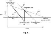
- the expected time until a maintenance operation may be derived from a line of best fit between respective points.
- two points one representing intensity after an actual cleaning or replacement 602, and another representing intensity after an actual cleaning 604 allow a line of best fit (if there were more points it would be a line of best fit according least squares or other scheme) to be drawn and extrapolated to a predicted threshold 612 for replacement, thereby yielding a predicted replacement point 610.
- the time scale may be operating hours or elapsed actual time.
- the disclosed subject matter includes a method of maintaining an ultraviolet air treatment system.
- the method includes detecting an intensity of at least one ultraviolet light source at successive points in time during operation thereof in an air treatment system.
- the method further includes applying signals representing the intensity to a controller and storing data responsive to the detected intensities in a data store.
- the controller at a first time, on a user output terminal, generates an indication that the at least one ultraviolet light source requires cleaning.
- the controller at a second time, on the user output terminal, generates an indication that the at least one ultraviolet light source requires replacement.
- the controller receives a maintenance indication where the maintenance indication is a signal indicating at least one of the completion of a cleaning of the ultraviolet light source and a replacement of the at least one ultraviolet light source.
- the generating operation that generates an indication that the at least one ultraviolet light source requires cleaning is responsive to the maintenance indication and stored data responsive to the intensity of the at least one ultraviolet light source immediately after maintenance indication.
- the disclosed subject matter includes a method of maintaining an ultraviolet air treatment system.
- the method includes detecting an intensity of at least one ultraviolet light source at successive points in time during operation thereof in an air treatment system.
- the method further includes applying signals representing the intensity to a controller and storing data responsive to the detected intensities in a data store.
- the controller at a first time, on a user output terminal, generates an indication that the at least one ultraviolet light source requires cleaning.
- the controller at a second time, on the user output terminal, generates an indication that the at least one ultraviolet light source requires replacement.
- the controller receives a maintenance indication where the maintenance indication is a signal indicating at least one of the completion of a cleaning of the ultraviolet light source and a replacement of the at least one ultraviolet light source.
- the generating an indication that the at least one ultraviolet light source requires replacing is responsive to the maintenance indication and stored data responsive to the intensity of the at least one ultraviolet light source at multiple points in time such that the indication that the ultraviolet lamp requires replacing is generated if multiple maintenance indications have been received by the controller indicating cleaning of the at least one ultraviolet light source.
- the disclosed subject matter includes a method of maintaining an ultraviolet air treatment system.
- the method applies to a system that includes a controller where the controller has at least one sensor and an output device and is configured to perform the method.
- the method includes detecting an intensity of at least one ultraviolet light source at successive points in time.
- the method further includes receiving an indication that the at least one ultraviolet light source has just been cleaned.
- the controller When the detected intensity is above a first threshold upon a first detecting after a receiving, the controller outputs no maintenance indication.
- the controller outputs a maintenance indication indicating to replace the ultraviolet light source.
- the controller When the detected intensity is below a second threshold upon a detecting subsequent to a first detecting after a receiving, the controller outputs a maintenance indication indicating to clean the ultraviolet light source.
- the first threshold corresponds to a lower intensity than the second threshold.
- the disclosed subject matter includes a method of maintaining an ultraviolet air treatment system, the system including a controller.
- the controller has at least one sensor and an output device and is configured to perform the method which includes detecting an intensity of at least one ultraviolet light source at successive points in time.
- the method further includes receiving an indication that the at least one ultraviolet light source has just been cleaned.
- the controller When the detected intensity is above a threshold upon a first detecting after a receiving, the controller outputs no maintenance indication.
- the controller outputs a maintenance indication indicating to replace the ultraviolet light source.
- the controller When the detected intensity is below the threshold upon a detecting subsequent to a first detecting after a receiving, the controller outputs a maintenance indication indicating to clean the ultraviolet light source.
- the at least one ultraviolet light sources may include multiple lamps in a ventilation plenum.
- the at least one ultraviolet light sources may include multiple lamps in a chamber downstream of at least one kitchen exhaust hood.
- the controller may include a programmable digital controller.
- the disclosed subject matter includes a system including an exhaust hood and a controller adapted for performing any of the methods described herein.
- the disclosed subject matter includes a controller configured for performing any of the recited methods.
- the disclosed subject matter includes a computer readable medium having instructions recorded thereon for performing any of the above recited methods.
- the foregoing medium may include instructions wherein the air treatment system includes a kitchen exhaust system.
- the foregoing controller may be configured for operation in a system that includes a kitchen exhaust system.
- the air treatment system may include a kitchen exhaust system in any of the foregoing embodiments.
- the maintenance indication may include an estimate of time until the maintenance is required.
- the disclosed subject matter includes a method of maintaining an ultraviolet air treatment system.
- the method includes detecting light output from an ultraviolet light source at multiple points in time. From a first trend in the data, the data representing multiple instances of the detecting, the a required first maintenance action is determined to elevate the light output from the light source and outputting an indication of the required maintenance action.
- the method further includes detecting a performance of the first maintenance action. From a second trend in the data representing multiple instance of the detecting in combination with the detecting a performance of the first maintenance event the method determines a required second maintenance action and outputting an indication of a need for the second maintenance action responsively thereto.
- the detecting a performance may include detecting a change in light output indicating the completion of the first maintenance action.
- the first maintenance action may include cleaning the ultraviolet light source.
- the second maintenance action may include replacing or repairing the ultraviolet light source.
- the outputting may include displaying a message on a user interface indicating, respectively, the need for the first and second maintenance actions.
- the detecting a performance may include receiving a user input indicating the completion of the first maintenance action.
- the disclosed subject matter includes a method of maintaining an ultraviolet air treatment system.
- the method includes detecting light output from an ultraviolet light source at multiple points in time and when the light output drops to a first level, outputting an indication that the ultraviolet light source needs to be cleaned.
- an indication that the ultraviolet light source needs to be changed is output by the controller.
- the outputting of an indication that the ultraviolet light source needs to be changed may be performed in response to a subsequent to the time approximately contemporaneous with the detection that the ultraviolet light source has been cleaned.
- the at least one ultraviolet light sources may include multiple lamps in a ventilation plenum.
- the at least one ultraviolet light sources may include multiple lamps in a chamber downstream of at least one kitchen exhaust hood.
- the controller may be a programmable digital controller.
- the disclosed subject matter includes a system including an exhaust hood and a controller adapted for performing any of the methods or a controller configured for performing any of the methods, or a computer readable medium having instructions recorded thereon for performing any of the methods.
- modules, processes, systems, and sections described above can be implemented in hardware, hardware programmed by software, software instruction stored on a non-transitory computer readable medium or a combination of the above.
- a method for indicating a maintenance operation can be implemented, for example, using a processor configured to execute a sequence of programmed instructions stored on a non-transitory computer readable medium.
- the processor can include, but not be limited to, a personal computer or workstation or other such computing system that includes a processor, microprocessor, microcontroller device, or is comprised of control logic including integrated circuits such as, for example, an Application Specific Integrated Circuit (ASIC).
- ASIC Application Specific Integrated Circuit
- the instructions can be compiled from source code instructions provided in accordance with a programming language such as Java, C++, C#.net or the like.
- the instructions can also comprise code and data objects provided in accordance with, for example, the Visual BasicTM language, LabVIEW, or another structured or object-oriented programming language.
- the sequence of programmed instructions and data associated therewith can be stored in a non-transitory computer-readable medium such as a computer memory or storage device which may be any suitable memory apparatus, such as, but not limited to read-only memory (ROM), programmable read-only memory (PROM), electrically erasable programmable read-only memory (EEPROM), random-access memory (RAM), flash memory, disk drive and the like.
- ROM read-only memory
- PROM programmable read-only memory
- EEPROM electrically erasable programmable read-only memory
- RAM random-access memory
- flash memory disk drive and the like.
- modules, processes, systems, and sections can be implemented as a single processor or as a distributed processor. Further, it should be appreciated that the steps mentioned above may be performed on a single or distributed processor (single and/or multi-core). Also, the processes, modules, and sub-modules described in the various figures of and for embodiments above may be distributed across multiple computers or systems or may be co-located in a single processor or system. Exemplary structural embodiment alternatives suitable for implementing the modules, sections, systems, means, or processes described herein are provided below.
- the modules, processors or systems described above can be implemented as a programmed general purpose computer, an electronic device programmed with microcode, a hard-wired analog logic circuit, software stored on a computer-readable medium or signal, an optical computing device, a networked system of electronic and/or optical devices, a special purpose computing device, an integrated circuit device, a semiconductor chip, and a software module or object stored on a computer-readable medium or signal, for example.
- Embodiments of the method and system may be implemented on a general-purpose computer, a special-purpose computer, a programmed microprocessor or microcontroller and peripheral integrated circuit element, an ASIC or other integrated circuit, a digital signal processor, a hardwired electronic or logic circuit such as a discrete element circuit, a programmed logic circuit such as a programmable logic device (PLD), programmable logic array (PLA), field-programmable gate array (FPGA), programmable array logic (PAL) device, or the like.
- PLD programmable logic device
- PLA programmable logic array
- FPGA field-programmable gate array
- PAL programmable array logic
- any process capable of implementing the functions or steps described herein can be used to implement embodiments of the method, system, or a computer program product (software program stored on a non-transitory computer readable medium).
- embodiments of the disclosed method, system, and computer program product may be readily implemented, fully or partially, in software using, for example, object or object-oriented software development environments that provide portable source code that can be used on a variety of computer platforms.
- embodiments of the disclosed method, system, and computer program product can be implemented partially or fully in hardware using, for example, standard logic circuits or a very-large-scale integration (VLSI) design.
- VLSI very-large-scale integration
- Other hardware or software can be used to implement embodiments depending on the speed and/or efficiency requirements of the systems, the particular function, and/or particular software or hardware system, microprocessor, or microcomputer being utilized.
- Embodiments of the method, system, and computer program product can be implemented in hardware and/or software using any known or later developed systems or structures, devices and/or software by those of ordinary skill in the applicable art from the function description provided herein and with a general basic knowledge of ventilation control and/or computer programming arts.
- embodiments of the disclosed method, system, and computer program product can be implemented in software executed on a programmed general purpose computer, a special purpose computer, a microprocessor, or the like.
Landscapes
- Chemical & Material Sciences (AREA)
- Health & Medical Sciences (AREA)
- Engineering & Computer Science (AREA)
- Life Sciences & Earth Sciences (AREA)
- General Health & Medical Sciences (AREA)
- Chemical Kinetics & Catalysis (AREA)
- Analytical Chemistry (AREA)
- Physics & Mathematics (AREA)
- Epidemiology (AREA)
- Veterinary Medicine (AREA)
- Public Health (AREA)
- Animal Behavior & Ethology (AREA)
- General Physics & Mathematics (AREA)
- Combustion & Propulsion (AREA)
- General Engineering & Computer Science (AREA)
- Mechanical Engineering (AREA)
- Toxicology (AREA)
- Spectroscopy & Molecular Physics (AREA)
- General Chemical & Material Sciences (AREA)
- Oil, Petroleum & Natural Gas (AREA)
- Biochemistry (AREA)
- Immunology (AREA)
- Pathology (AREA)
- Ventilation (AREA)
- Cleaning In General (AREA)
- Apparatus For Disinfection Or Sterilisation (AREA)
- Physical Or Chemical Processes And Apparatus (AREA)
- Air Conditioning Control Device (AREA)
- Investigating Or Analysing Materials By Optical Means (AREA)
- Circuit Arrangement For Electric Light Sources In General (AREA)
Claims (5)
- Verfahren zur Wartung einer Abluftbehandlungsvorrichtung (104), die nachgeordnet zu einer Dunstabzugshaube positioniert ist, umfassend:kontinuierliches Detektieren einer Intensität von mindestens einer Ultraviolettlichtquelle (10) mittels eines Sensors (102);an aufeinander folgenden Zeitpunkten während des Betriebs desselben in der Abluftbehandlungsvorrichtung (104) Pollen des Sensors (102) mit einer Steuerung (100), um Signale, welche die Intensität repräsentieren, an eine Steuerung (100) anzulegen; Speichern von Daten in Reaktion auf die detektierten Intensitäten in einem Datenspeicher (108);dadurch gekennzeichnet, dass das Verfahren des Weiteren umfasst:die Steuerung generiert zu einer ersten Zeit an einem Benutzerausgabeendgerät (106) eine Angabe, dass die mindestens eine Ultraviolettlichtquelle (10) gereinigt werden muss, wenn die detektierte Intensität unter einem zweiten Schwellenwert liegt;die Steuerung ermittelt zu einer zweiten Zeit nach der ersten Zeit, ob ein erster Befehl von einem Benutzer über das Benutzerausgabeendgerät (106) als eine erste Wartungsangabe eingegeben worden ist, die den Abschluss einer Reinigung der mindestens einen Ultraviolettlichtquelle (10) angibt;die Steuerung (100) generiert zu einer dritten Zeit nach der zweiten Zeit an dem Benutzerausgabeendgerät (106) eine Angabe, dass die mindestens eine Ultraviolettlichtquelle (10) ersetzt werden muss, falls die Intensität der mindestens einen Ultraviolettlichtquelle (10) nach der Reinigung nicht oberhalb eines ersten Schwellenwerts liegt, wobei der erste Schwellenwert einer niedrigeren Intensität als der zweite Schwellenwert entspricht;die Steuerung (100) ermittelt zu einer vierten Zeit nach der dritten Zeit, ob ein zweiter Befehl von einem Benutzer über das Benutzerausgabeendgerät (106) als eine zweite Wartungsangabe eingegeben worden ist, die den Abschluss eines Ersetzens der mindestens einen Ultraviolettlichtquelle (10) angibt, und empfangen worden ist; unddie Steuerung (100) verhindert den Betrieb der Dunstabzugshaube, falls keine Wartungsangabe über eine Eingabe seitens des Benutzers über das Benutzerausgabeendgerät innerhalb eines vordefinierten Zeitraums oder einer vordefinierten Anzahl von Hochfahrvorgängen des Systems empfangen wurde.
- Verfahren nach Anspruch 1, wobei die mindestens eine Ultraviolettlichtquelle (10) mehrere Lampen in einem Abluftsammelraum einschließt.
- Verfahren nach einem der vorhergehenden Ansprüche, wobei die mindestens eine Ultraviolettlichtquelle (10) mehrere Lampen in einer Kammer nachgeordnet zu mindestens einer Küchendunstabzugshaube einschließt.
- Verfahren nach einem der vorhergehenden Ansprüche, wobei die Steuerung (100) eine programmierbare digitale Steuerung ist.
- Abluftbehandlungsvorrichtung, umfassend:eine Dunstabzugshaube;mindestens eine Ultraviolettlichtquelle (10), die nachgeordnet zu der Dunstabzugshaube positioniert ist;eine Steuerung (100), die ausgestaltet ist, um jedwedes der Verfahren der Ansprüche 1 bis 4 durchzuführen;einen Sensor (102), der ausgestaltet ist, um kontinuierlich die Intensität der mindestens einen Ultraviolettlichtquelle (10) zu detektieren und mit der Steuerung (100) zu kommunizieren;einen Datenspeicher (108) zum Speichern von Daten in Reaktion auf die detektierten Intensitäten; und ein Benutzerausgabeendgerät (106) zum Bereitstellen einer Angabe an einen Benutzer, wenn eine Aufforderung durch die Steuerung (100) erfolgt, und zum Kommunizieren von Benutzereingaben an die Steuerung (100).
Priority Applications (1)
| Application Number | Priority Date | Filing Date | Title |
|---|---|---|---|
| PL11846235T PL2646064T3 (pl) | 2010-12-05 | 2011-12-05 | Sposoby i urządzenia do monitorowania z wykorzystaniem promieniowania ultrafioletowego |
Applications Claiming Priority (2)
| Application Number | Priority Date | Filing Date | Title |
|---|---|---|---|
| US41986710P | 2010-12-05 | 2010-12-05 | |
| PCT/US2011/063344 WO2012078529A1 (en) | 2010-12-05 | 2011-12-05 | Ultraviolet monitoring systems, methods, and devices |
Publications (3)
| Publication Number | Publication Date |
|---|---|
| EP2646064A1 EP2646064A1 (de) | 2013-10-09 |
| EP2646064A4 EP2646064A4 (de) | 2014-10-15 |
| EP2646064B1 true EP2646064B1 (de) | 2022-04-27 |
Family
ID=46207470
Family Applications (1)
| Application Number | Title | Priority Date | Filing Date |
|---|---|---|---|
| EP11846235.7A Active EP2646064B1 (de) | 2010-12-05 | 2011-12-05 | Verfahren und vorrichtungen zur ultraviolettüberwachung |
Country Status (15)
| Country | Link |
|---|---|
| US (2) | US9119891B2 (de) |
| EP (1) | EP2646064B1 (de) |
| JP (1) | JP6017444B2 (de) |
| KR (1) | KR101760979B1 (de) |
| CN (2) | CN103429275B (de) |
| AU (1) | AU2011338675B2 (de) |
| BR (1) | BR112013013941B1 (de) |
| CA (1) | CA2820243C (de) |
| DK (1) | DK2646064T3 (de) |
| GB (1) | GB2500137B (de) |
| MX (1) | MX2013006280A (de) |
| PL (1) | PL2646064T3 (de) |
| SG (2) | SG10201509968TA (de) |
| WO (1) | WO2012078529A1 (de) |
| ZA (1) | ZA201304991B (de) |
Families Citing this family (13)
| Publication number | Priority date | Publication date | Assignee | Title |
|---|---|---|---|---|
| CA2989812C (en) * | 2015-06-26 | 2023-09-26 | Kenall Manufacturing Company | Method of providing doses of light sufficient to deactivate dangerous pathogens throughout a volumetric space over a period of time |
| US10363325B2 (en) | 2015-06-26 | 2019-07-30 | Kenall Manufacturing Company | Lighting device that deactivates dangerous pathogens while providing visually appealing light |
| CN106287884A (zh) * | 2016-08-26 | 2017-01-04 | 建研科技发展(深圳)有限公司 | 一种uv除油烟罩的清洗方法及系统 |
| US10488056B2 (en) | 2017-06-01 | 2019-11-26 | Illinois Tool Works Inc. | Cooking exhaust hood ventilation system |
| TWI746907B (zh) * | 2017-12-05 | 2021-11-21 | 日商斯庫林集團股份有限公司 | 煙霧判定方法、基板處理方法及基板處理裝置 |
| EP4029355B1 (de) * | 2019-09-12 | 2024-01-10 | Trojan Technologies Group ULC | Ausgangsmodulation einer ultravioletten lampe |
| JP7536039B2 (ja) * | 2019-12-13 | 2024-08-19 | 株式会社荏原製作所 | 基板洗浄装置、研磨装置、バフ処理装置、基板洗浄方法、基板処理装置、および機械学習器 |
| US20220143257A1 (en) * | 2020-11-10 | 2022-05-12 | GE Precision Healthcare LLC | Uvc sterilization systems and methods for patient ventilation |
| US12259151B2 (en) * | 2021-01-21 | 2025-03-25 | Evolution Controls Inc. | HVAC motor automation control unit and adjustment methods and apparatus for same |
| CN113465039B (zh) * | 2021-04-29 | 2022-08-19 | 青岛海尔空调器有限总公司 | 用于空调器的控制方法及空调器 |
| CA3222094A1 (en) * | 2021-06-09 | 2022-12-15 | John Johnston | System and method for disinfection with ultraviolet light |
| CN114484746B (zh) * | 2022-01-11 | 2023-05-02 | Tcl空调器(中山)有限公司 | 空调器自清洁方法、装置、电子设备及存储介质 |
| JP7780471B2 (ja) * | 2022-04-26 | 2025-12-04 | ダイキン工業株式会社 | 空気処理装置 |
Family Cites Families (21)
| Publication number | Priority date | Publication date | Assignee | Title |
|---|---|---|---|---|
| JP2522866B2 (ja) | 1991-07-02 | 1996-08-07 | 日立造船株式会社 | プレス機におけるワ―ク搬送装置 |
| JPH1057954A (ja) * | 1996-08-14 | 1998-03-03 | Nippon Photo Sci:Kk | 紫外線照射装置の紫外線照射量測定装置 |
| US6037598A (en) | 1998-01-28 | 2000-03-14 | Tetra Laval Holdings & Finance, Sa | Arrangement on an ultraviolet sterilization system |
| US7318856B2 (en) * | 1998-11-05 | 2008-01-15 | Sharper Image Corporation | Air treatment apparatus having an electrode extending along an axis which is substantially perpendicular to an air flow path |
| US6818177B1 (en) * | 1999-11-09 | 2004-11-16 | Mark Turcotte | Ultraviolet air purification systems |
| US6849234B2 (en) * | 2001-11-26 | 2005-02-01 | Honeywell International Inc. | System and method for controlling an ultraviolet air treatment device for return air duct applications |
| US20030170151A1 (en) * | 2002-03-08 | 2003-09-11 | Hunter Charles Eric | Biohazard treatment systems |
| US20040200975A1 (en) | 2003-04-14 | 2004-10-14 | Brown Dale Marius | Ultraviolet sensors for monitoring energy in the germicidal wavelengths |
| US20040224417A1 (en) | 2003-05-01 | 2004-11-11 | Ziyi Wang | Ultraviolet lamp performance measurement |
| CN2855519Y (zh) * | 2004-01-22 | 2007-01-10 | 高超明智公司 | 空气输送调节装置 |
| ES2329056T3 (es) | 2004-04-20 | 2009-11-20 | Guido Kohler | Dispositivo de esterilizacion de fluidos. |
| US7332124B2 (en) * | 2004-04-23 | 2008-02-19 | Miller Thomson, Llp | Ultraviolet device |
| CN2699891Y (zh) * | 2004-06-17 | 2005-05-18 | 北京市知识产权服务中心 | 光触媒空气消毒机 |
| US20060130663A1 (en) * | 2004-12-20 | 2006-06-22 | General Electric Company | System and method of air quality control for air-conditioning devices |
| JP4468221B2 (ja) * | 2005-03-29 | 2010-05-26 | 株式会社東芝 | 紫外線照射を利用した水処理システム |
| SE528877C2 (sv) * | 2005-07-07 | 2007-03-06 | Lars-Erik Lejondahl | System för behandling av förorenad luft med UV-ljus |
| CN201007679Y (zh) * | 2005-11-16 | 2008-01-16 | 黄志坚 | 紫外线强度检测/指示装置 |
| US7705744B2 (en) * | 2007-05-24 | 2010-04-27 | Cutsforth Products, Inc. | Monitoring systems and methods for monitoring the condition of one or more components of an electrical device |
| EP2669651B1 (de) * | 2007-06-13 | 2020-12-09 | OY Halton Group, Ltd. | Verschmutzungsdetektor zur erkennung von schmierfettablagerungen in kanälen |
| CA2675869A1 (en) * | 2008-08-18 | 2010-02-18 | Sanuvox Technologies Inc. | Controller for uv light purification system |
| WO2012009353A1 (en) | 2010-07-12 | 2012-01-19 | Nordson Corporation | Ultraviolet lamp system and method for controlling emitted ultraviolet light |
-
2011
- 2011-12-05 EP EP11846235.7A patent/EP2646064B1/de active Active
- 2011-12-05 WO PCT/US2011/063344 patent/WO2012078529A1/en not_active Ceased
- 2011-12-05 CA CA2820243A patent/CA2820243C/en active Active
- 2011-12-05 JP JP2013543240A patent/JP6017444B2/ja active Active
- 2011-12-05 KR KR1020137017523A patent/KR101760979B1/ko active Active
- 2011-12-05 PL PL11846235T patent/PL2646064T3/pl unknown
- 2011-12-05 CN CN201180066864.8A patent/CN103429275B/zh active Active
- 2011-12-05 MX MX2013006280A patent/MX2013006280A/es active IP Right Grant
- 2011-12-05 DK DK11846235.7T patent/DK2646064T3/da active
- 2011-12-05 CN CN201510225250.XA patent/CN104898544B/zh active Active
- 2011-12-05 AU AU2011338675A patent/AU2011338675B2/en active Active
- 2011-12-05 BR BR112013013941-2A patent/BR112013013941B1/pt active IP Right Grant
- 2011-12-05 SG SG10201509968TA patent/SG10201509968TA/en unknown
- 2011-12-05 US US13/991,642 patent/US9119891B2/en active Active
- 2011-12-05 GB GB1309792.8A patent/GB2500137B/en active Active
- 2011-12-05 SG SG2013043153A patent/SG190995A1/en unknown
-
2013
- 2013-07-03 ZA ZA2013/04991A patent/ZA201304991B/en unknown
-
2015
- 2015-07-09 US US14/795,756 patent/US9645009B2/en active Active
Also Published As
| Publication number | Publication date |
|---|---|
| PL2646064T3 (pl) | 2022-06-20 |
| CN104898544A (zh) | 2015-09-09 |
| EP2646064A4 (de) | 2014-10-15 |
| GB2500137A (en) | 2013-09-11 |
| AU2011338675B2 (en) | 2016-04-14 |
| US20150308890A1 (en) | 2015-10-29 |
| KR20130138286A (ko) | 2013-12-18 |
| CN103429275A (zh) | 2013-12-04 |
| SG190995A1 (en) | 2013-07-31 |
| JP6017444B2 (ja) | 2016-11-02 |
| BR112013013941B1 (pt) | 2019-10-15 |
| SG10201509968TA (en) | 2016-01-28 |
| MX2013006280A (es) | 2013-08-01 |
| ZA201304991B (en) | 2016-02-24 |
| CA2820243A1 (en) | 2012-06-14 |
| JP2014501581A (ja) | 2014-01-23 |
| EP2646064A1 (de) | 2013-10-09 |
| BR112013013941A2 (pt) | 2016-08-16 |
| CA2820243C (en) | 2017-10-17 |
| AU2011338675A1 (en) | 2013-07-18 |
| US9645009B2 (en) | 2017-05-09 |
| GB2500137B (en) | 2014-09-03 |
| US9119891B2 (en) | 2015-09-01 |
| CN104898544B (zh) | 2018-11-06 |
| US20130287627A1 (en) | 2013-10-31 |
| DK2646064T3 (da) | 2022-05-16 |
| GB201309792D0 (en) | 2013-07-17 |
| WO2012078529A1 (en) | 2012-06-14 |
| KR101760979B1 (ko) | 2017-07-24 |
| CN103429275B (zh) | 2015-11-25 |
Similar Documents
| Publication | Publication Date | Title |
|---|---|---|
| CA2820243C (en) | Ultraviolet monitoring systems, methods, and devices | |
| US7771589B2 (en) | Screen blockage measurement and flow performance optimization system | |
| CN105299839B (zh) | 过滤网状态检测方法和装置 | |
| US20170189846A1 (en) | Air Purifier, Method for Determining Time to Replace Filter Thereof, and Device and Method for Determining Filer Replacement Time Pressure Differential Therefor | |
| KR20180134515A (ko) | 초미세먼지 측정 장치 및 그 방법 | |
| EP2946219B2 (de) | Verfahren, vorrichtung und computerprogrammprodukt zum bestimmen von störungen in einem beleuchtungssystem | |
| CN105080205A (zh) | 净化器滤网过期提示方法和装置及净化器 | |
| CN110160211A (zh) | 空调室内机滤网清洗提醒系统及其方法和空调器 | |
| TWI646420B (zh) | 空調設備的濾網壽命告警系統及告警方法 | |
| TW201727073A (zh) | 真空泵之判斷系統及真空泵 | |
| CN113906259B (zh) | 用于检测颗粒过滤器的状态的系统和方法 | |
| KR20160016504A (ko) | 공기정화기 및 이의 필터교체시기 결정 방법 | |
| GB2512708A (en) | Ultraviolet monitoring systems, methods, and devices | |
| EP4462195A1 (de) | Luftqualitätsüberwachung | |
| CN112439265B (zh) | 过滤件寿命提醒方法、过滤件寿命提醒系统及空气净化器 | |
| US20230221175A1 (en) | Prediction and detection of filter clogs | |
| CN112944549A (zh) | 用于清理集尘单元的方法、装置、静电集尘模块及空调器 | |
| CN111649400A (zh) | 一种空气净化组件的控制方法、装置及空调器 | |
| JP2026060338A (ja) | 性能評価システム、汚染物質除去装置、情報処理装置 | |
| CN121004154A (zh) | 蒸烤箱净化装置、蒸烤箱净化控制方法和蒸烤箱 | |
| JP2025173715A (ja) | 制御装置及び処理システム | |
| CN114234351A (zh) | 用于空调器内风扇清洁的方法及装置、空调器、可读存储介质 | |
| CN101217984A (zh) | 用紫外光处理污染的空气的系统 |
Legal Events
| Date | Code | Title | Description |
|---|---|---|---|
| PUAI | Public reference made under article 153(3) epc to a published international application that has entered the european phase |
Free format text: ORIGINAL CODE: 0009012 |
|
| 17P | Request for examination filed |
Effective date: 20130610 |
|
| AK | Designated contracting states |
Kind code of ref document: A1 Designated state(s): AL AT BE BG CH CY CZ DE DK EE ES FI FR GB GR HR HU IE IS IT LI LT LU LV MC MK MT NL NO PL PT RO RS SE SI SK SM TR |
|
| RIN1 | Information on inventor provided before grant (corrected) |
Inventor name: LIVCHAK, ANDREY, V. Inventor name: RACZEWSKI, CHESTER |
|
| DAX | Request for extension of the european patent (deleted) | ||
| RAP1 | Party data changed (applicant data changed or rights of an application transferred) |
Owner name: OY HALTON GROUP LTD. |
|
| A4 | Supplementary search report drawn up and despatched |
Effective date: 20140916 |
|
| RIC1 | Information provided on ipc code assigned before grant |
Ipc: A61L 9/20 20060101AFI20140910BHEP |
|
| STAA | Information on the status of an ep patent application or granted ep patent |
Free format text: STATUS: EXAMINATION IS IN PROGRESS |
|
| 17Q | First examination report despatched |
Effective date: 20170324 |
|
| REG | Reference to a national code |
Ref country code: DE Ref legal event code: R079 Ref document number: 602011072820 Country of ref document: DE Free format text: PREVIOUS MAIN CLASS: A61L0009200000 Ipc: F24C0015200000 |
|
| RIC1 | Information provided on ipc code assigned before grant |
Ipc: B01D 53/00 20060101ALI20210205BHEP Ipc: F24C 15/20 20060101AFI20210205BHEP |
|
| GRAP | Despatch of communication of intention to grant a patent |
Free format text: ORIGINAL CODE: EPIDOSNIGR1 |
|
| STAA | Information on the status of an ep patent application or granted ep patent |
Free format text: STATUS: GRANT OF PATENT IS INTENDED |
|
| INTG | Intention to grant announced |
Effective date: 20211004 |
|
| GRAS | Grant fee paid |
Free format text: ORIGINAL CODE: EPIDOSNIGR3 |
|
| GRAA | (expected) grant |
Free format text: ORIGINAL CODE: 0009210 |
|
| STAA | Information on the status of an ep patent application or granted ep patent |
Free format text: STATUS: THE PATENT HAS BEEN GRANTED |
|
| RAP3 | Party data changed (applicant data changed or rights of an application transferred) |
Owner name: OY HALTON GROUP LTD. |
|
| AK | Designated contracting states |
Kind code of ref document: B1 Designated state(s): AL AT BE BG CH CY CZ DE DK EE ES FI FR GR HR HU IE IS IT LI LT LU LV MC MK MT NL NO PL PT RO RS SE SI SK SM TR |
|
| RBV | Designated contracting states (corrected) |
Designated state(s): AL AT BE BG CH CY CZ DE DK EE ES FI FR GR HR HU IE IS IT LI LT LU LV MC MK MT NL NO PL PT RO RS SE SI SK SM TR |
|
| REG | Reference to a national code |
Ref country code: CH Ref legal event code: EP |
|
| REG | Reference to a national code |
Ref country code: AT Ref legal event code: REF Ref document number: 1487193 Country of ref document: AT Kind code of ref document: T Effective date: 20220515 |
|
| REG | Reference to a national code |
Ref country code: DK Ref legal event code: T3 Effective date: 20220509 |
|
| REG | Reference to a national code |
Ref country code: SE Ref legal event code: TRGR |
|
| REG | Reference to a national code |
Ref country code: DE Ref legal event code: R096 Ref document number: 602011072820 Country of ref document: DE |
|
| REG | Reference to a national code |
Ref country code: FI Ref legal event code: FGE |
|
| REG | Reference to a national code |
Ref country code: IE Ref legal event code: FG4D |
|
| REG | Reference to a national code |
Ref country code: NL Ref legal event code: FP |
|
| REG | Reference to a national code |
Ref country code: NO Ref legal event code: T2 Effective date: 20220427 |
|
| REG | Reference to a national code |
Ref country code: LT Ref legal event code: MG9D |
|
| PG25 | Lapsed in a contracting state [announced via postgrant information from national office to epo] |
Ref country code: PT Free format text: LAPSE BECAUSE OF FAILURE TO SUBMIT A TRANSLATION OF THE DESCRIPTION OR TO PAY THE FEE WITHIN THE PRESCRIBED TIME-LIMIT Effective date: 20220829 Ref country code: LT Free format text: LAPSE BECAUSE OF FAILURE TO SUBMIT A TRANSLATION OF THE DESCRIPTION OR TO PAY THE FEE WITHIN THE PRESCRIBED TIME-LIMIT Effective date: 20220427 Ref country code: HR Free format text: LAPSE BECAUSE OF FAILURE TO SUBMIT A TRANSLATION OF THE DESCRIPTION OR TO PAY THE FEE WITHIN THE PRESCRIBED TIME-LIMIT Effective date: 20220427 Ref country code: GR Free format text: LAPSE BECAUSE OF FAILURE TO SUBMIT A TRANSLATION OF THE DESCRIPTION OR TO PAY THE FEE WITHIN THE PRESCRIBED TIME-LIMIT Effective date: 20220728 Ref country code: ES Free format text: LAPSE BECAUSE OF FAILURE TO SUBMIT A TRANSLATION OF THE DESCRIPTION OR TO PAY THE FEE WITHIN THE PRESCRIBED TIME-LIMIT Effective date: 20220427 Ref country code: BG Free format text: LAPSE BECAUSE OF FAILURE TO SUBMIT A TRANSLATION OF THE DESCRIPTION OR TO PAY THE FEE WITHIN THE PRESCRIBED TIME-LIMIT Effective date: 20220727 |
|
| PG25 | Lapsed in a contracting state [announced via postgrant information from national office to epo] |
Ref country code: RS Free format text: LAPSE BECAUSE OF FAILURE TO SUBMIT A TRANSLATION OF THE DESCRIPTION OR TO PAY THE FEE WITHIN THE PRESCRIBED TIME-LIMIT Effective date: 20220427 Ref country code: LV Free format text: LAPSE BECAUSE OF FAILURE TO SUBMIT A TRANSLATION OF THE DESCRIPTION OR TO PAY THE FEE WITHIN THE PRESCRIBED TIME-LIMIT Effective date: 20220427 Ref country code: IS Free format text: LAPSE BECAUSE OF FAILURE TO SUBMIT A TRANSLATION OF THE DESCRIPTION OR TO PAY THE FEE WITHIN THE PRESCRIBED TIME-LIMIT Effective date: 20220827 |
|
| REG | Reference to a national code |
Ref country code: DE Ref legal event code: R097 Ref document number: 602011072820 Country of ref document: DE |
|
| PG25 | Lapsed in a contracting state [announced via postgrant information from national office to epo] |
Ref country code: SM Free format text: LAPSE BECAUSE OF FAILURE TO SUBMIT A TRANSLATION OF THE DESCRIPTION OR TO PAY THE FEE WITHIN THE PRESCRIBED TIME-LIMIT Effective date: 20220427 Ref country code: SK Free format text: LAPSE BECAUSE OF FAILURE TO SUBMIT A TRANSLATION OF THE DESCRIPTION OR TO PAY THE FEE WITHIN THE PRESCRIBED TIME-LIMIT Effective date: 20220427 Ref country code: RO Free format text: LAPSE BECAUSE OF FAILURE TO SUBMIT A TRANSLATION OF THE DESCRIPTION OR TO PAY THE FEE WITHIN THE PRESCRIBED TIME-LIMIT Effective date: 20220427 Ref country code: EE Free format text: LAPSE BECAUSE OF FAILURE TO SUBMIT A TRANSLATION OF THE DESCRIPTION OR TO PAY THE FEE WITHIN THE PRESCRIBED TIME-LIMIT Effective date: 20220427 Ref country code: CZ Free format text: LAPSE BECAUSE OF FAILURE TO SUBMIT A TRANSLATION OF THE DESCRIPTION OR TO PAY THE FEE WITHIN THE PRESCRIBED TIME-LIMIT Effective date: 20220427 |
|
| PLBE | No opposition filed within time limit |
Free format text: ORIGINAL CODE: 0009261 |
|
| STAA | Information on the status of an ep patent application or granted ep patent |
Free format text: STATUS: NO OPPOSITION FILED WITHIN TIME LIMIT |
|
| PG25 | Lapsed in a contracting state [announced via postgrant information from national office to epo] |
Ref country code: AL Free format text: LAPSE BECAUSE OF FAILURE TO SUBMIT A TRANSLATION OF THE DESCRIPTION OR TO PAY THE FEE WITHIN THE PRESCRIBED TIME-LIMIT Effective date: 20220427 |
|
| 26N | No opposition filed |
Effective date: 20230130 |
|
| PG25 | Lapsed in a contracting state [announced via postgrant information from national office to epo] |
Ref country code: SI Free format text: LAPSE BECAUSE OF FAILURE TO SUBMIT A TRANSLATION OF THE DESCRIPTION OR TO PAY THE FEE WITHIN THE PRESCRIBED TIME-LIMIT Effective date: 20220427 |
|
| P01 | Opt-out of the competence of the unified patent court (upc) registered |
Effective date: 20230505 |
|
| REG | Reference to a national code |
Ref country code: BE Ref legal event code: MM Effective date: 20221231 |
|
| PG25 | Lapsed in a contracting state [announced via postgrant information from national office to epo] |
Ref country code: LU Free format text: LAPSE BECAUSE OF NON-PAYMENT OF DUE FEES Effective date: 20221205 |
|
| PG25 | Lapsed in a contracting state [announced via postgrant information from national office to epo] |
Ref country code: IE Free format text: LAPSE BECAUSE OF NON-PAYMENT OF DUE FEES Effective date: 20221205 |
|
| PG25 | Lapsed in a contracting state [announced via postgrant information from national office to epo] |
Ref country code: BE Free format text: LAPSE BECAUSE OF NON-PAYMENT OF DUE FEES Effective date: 20221231 |
|
| PG25 | Lapsed in a contracting state [announced via postgrant information from national office to epo] |
Ref country code: HU Free format text: LAPSE BECAUSE OF FAILURE TO SUBMIT A TRANSLATION OF THE DESCRIPTION OR TO PAY THE FEE WITHIN THE PRESCRIBED TIME-LIMIT; INVALID AB INITIO Effective date: 20111205 |
|
| REG | Reference to a national code |
Ref country code: AT Ref legal event code: UEP Ref document number: 1487193 Country of ref document: AT Kind code of ref document: T Effective date: 20220427 |
|
| PG25 | Lapsed in a contracting state [announced via postgrant information from national office to epo] |
Ref country code: CY Free format text: LAPSE BECAUSE OF FAILURE TO SUBMIT A TRANSLATION OF THE DESCRIPTION OR TO PAY THE FEE WITHIN THE PRESCRIBED TIME-LIMIT Effective date: 20220427 |
|
| PG25 | Lapsed in a contracting state [announced via postgrant information from national office to epo] |
Ref country code: MK Free format text: LAPSE BECAUSE OF FAILURE TO SUBMIT A TRANSLATION OF THE DESCRIPTION OR TO PAY THE FEE WITHIN THE PRESCRIBED TIME-LIMIT Effective date: 20220427 |
|
| PG25 | Lapsed in a contracting state [announced via postgrant information from national office to epo] |
Ref country code: MC Free format text: LAPSE BECAUSE OF FAILURE TO SUBMIT A TRANSLATION OF THE DESCRIPTION OR TO PAY THE FEE WITHIN THE PRESCRIBED TIME-LIMIT Effective date: 20220427 |
|
| PG25 | Lapsed in a contracting state [announced via postgrant information from national office to epo] |
Ref country code: TR Free format text: LAPSE BECAUSE OF FAILURE TO SUBMIT A TRANSLATION OF THE DESCRIPTION OR TO PAY THE FEE WITHIN THE PRESCRIBED TIME-LIMIT Effective date: 20220427 Ref country code: MC Free format text: LAPSE BECAUSE OF FAILURE TO SUBMIT A TRANSLATION OF THE DESCRIPTION OR TO PAY THE FEE WITHIN THE PRESCRIBED TIME-LIMIT Effective date: 20220427 |
|
| PG25 | Lapsed in a contracting state [announced via postgrant information from national office to epo] |
Ref country code: MT Free format text: LAPSE BECAUSE OF FAILURE TO SUBMIT A TRANSLATION OF THE DESCRIPTION OR TO PAY THE FEE WITHIN THE PRESCRIBED TIME-LIMIT Effective date: 20220427 |
|
| PG25 | Lapsed in a contracting state [announced via postgrant information from national office to epo] |
Ref country code: BG Free format text: LAPSE BECAUSE OF FAILURE TO SUBMIT A TRANSLATION OF THE DESCRIPTION OR TO PAY THE FEE WITHIN THE PRESCRIBED TIME-LIMIT Effective date: 20220427 |
|
| PG25 | Lapsed in a contracting state [announced via postgrant information from national office to epo] |
Ref country code: BG Free format text: LAPSE BECAUSE OF FAILURE TO SUBMIT A TRANSLATION OF THE DESCRIPTION OR TO PAY THE FEE WITHIN THE PRESCRIBED TIME-LIMIT Effective date: 20220427 |
|
| REG | Reference to a national code |
Ref country code: CH Ref legal event code: U11 Free format text: ST27 STATUS EVENT CODE: U-0-0-U10-U11 (AS PROVIDED BY THE NATIONAL OFFICE) Effective date: 20260101 |
|
| PGFP | Annual fee paid to national office [announced via postgrant information from national office to epo] |
Ref country code: NO Payment date: 20251231 Year of fee payment: 15 |
|
| PGFP | Annual fee paid to national office [announced via postgrant information from national office to epo] |
Ref country code: AT Payment date: 20251230 Year of fee payment: 15 |
|
| PGFP | Annual fee paid to national office [announced via postgrant information from national office to epo] |
Ref country code: IT Payment date: 20251219 Year of fee payment: 15 Ref country code: FI Payment date: 20251226 Year of fee payment: 15 Ref country code: DK Payment date: 20251226 Year of fee payment: 15 |
|
| PGFP | Annual fee paid to national office [announced via postgrant information from national office to epo] |
Ref country code: NL Payment date: 20251226 Year of fee payment: 15 Ref country code: FR Payment date: 20251226 Year of fee payment: 15 |
|
| PGFP | Annual fee paid to national office [announced via postgrant information from national office to epo] |
Ref country code: SE Payment date: 20251227 Year of fee payment: 15 |
|
| PGFP | Annual fee paid to national office [announced via postgrant information from national office to epo] |
Ref country code: PL Payment date: 20251119 Year of fee payment: 15 |
|
| PGFP | Annual fee paid to national office [announced via postgrant information from national office to epo] |
Ref country code: DE Payment date: 20251229 Year of fee payment: 15 |
|
| PGFP | Annual fee paid to national office [announced via postgrant information from national office to epo] |
Ref country code: CH Payment date: 20260101 Year of fee payment: 15 |