EP2645079A2 - Härtetester - Google Patents
Härtetester Download PDFInfo
- Publication number
- EP2645079A2 EP2645079A2 EP13157368.5A EP13157368A EP2645079A2 EP 2645079 A2 EP2645079 A2 EP 2645079A2 EP 13157368 A EP13157368 A EP 13157368A EP 2645079 A2 EP2645079 A2 EP 2645079A2
- Authority
- EP
- European Patent Office
- Prior art keywords
- sample
- stage
- image
- indenter
- offset
- Prior art date
- Legal status (The legal status is an assumption and is not a legal conclusion. Google has not performed a legal analysis and makes no representation as to the accuracy of the status listed.)
- Granted
Links
- 0 CCC(C)[C@@](C)(CCC(C1)OCNC1*=C)O Chemical compound CCC(C)[C@@](C)(CCC(C1)OCNC1*=C)O 0.000 description 1
Images





Classifications
-
- G—PHYSICS
- G01—MEASURING; TESTING
- G01N—INVESTIGATING OR ANALYSING MATERIALS BY DETERMINING THEIR CHEMICAL OR PHYSICAL PROPERTIES
- G01N3/00—Investigating strength properties of solid materials by application of mechanical stress
- G01N3/40—Investigating hardness or rebound hardness
- G01N3/42—Investigating hardness or rebound hardness by performing impressions under a steady load by indentors, e.g. sphere, pyramid
-
- G—PHYSICS
- G01—MEASURING; TESTING
- G01N—INVESTIGATING OR ANALYSING MATERIALS BY DETERMINING THEIR CHEMICAL OR PHYSICAL PROPERTIES
- G01N2203/00—Investigating strength properties of solid materials by application of mechanical stress
- G01N2203/0001—Type of application of the stress
- G01N2203/0003—Steady
-
- G—PHYSICS
- G01—MEASURING; TESTING
- G01N—INVESTIGATING OR ANALYSING MATERIALS BY DETERMINING THEIR CHEMICAL OR PHYSICAL PROPERTIES
- G01N2203/00—Investigating strength properties of solid materials by application of mechanical stress
- G01N2203/0014—Type of force applied
- G01N2203/0016—Tensile or compressive
- G01N2203/0019—Compressive
-
- G—PHYSICS
- G01—MEASURING; TESTING
- G01N—INVESTIGATING OR ANALYSING MATERIALS BY DETERMINING THEIR CHEMICAL OR PHYSICAL PROPERTIES
- G01N2203/00—Investigating strength properties of solid materials by application of mechanical stress
- G01N2203/0058—Kind of property studied
- G01N2203/0076—Hardness, compressibility or resistance to crushing
- G01N2203/0078—Hardness, compressibility or resistance to crushing using indentation
- G01N2203/008—Residual indentation measurement
Definitions
- the present invention relates to a hardness tester.
- a process to increase hardness of a surface is performed on metal components using a heat process in order to improve mechanical characteristics sought for the components. Then, a hardness test is performed to evaluate whether the hardness of the surface has attained the required hardness or whether a specified hardness has been obtained to a specific depth from the surface using the heat process.
- hardness testing methods of a pressing type are well known, such as the Vickers hardness test and the Knoop hardness test, which employ a hardness tester in which an indenter having a planar polygonal shape is pressed against a surface of a sample, then a degree of hardness of the sample is measured from a length of a diagonal line in a resulting polygonal indentation in the sample surface.
- Such hardness testing methods are widely used in evaluating mechanical characteristics of metallic materials (see, e.g., Japanese Patent Laid-open Publication No. 2004-286541 ).
- the Vickers hardness test employs a quadrangular pyramid diamond indenter and indicates the degree of hardness by a relationship between an average value for the length of the two diagonal lines of the quadrangular pyramid indentation formed in the surface of the sample and a pressing load of the indenter on the sample.
- the Knoop hardness test employs a rhomboid pyramid diamond indenter and indicates the degree of hardness by a relationship between the length of the longer of the diagonal lines of the rhomboid pyramid indentation formed in the surface of the sample and the pressing load of the indenter on the sample.
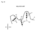
- test positions P are frequently specified at a predetermined pitch along straight lines L1, L2, and so on, which are oriented from an edge of a sample S toward a horizontal-direction interior of the sample S.
- a shape of the sample S is complex. Therefore, the test positions P are specified along the straight lines L1, L2, and so on, which are oriented in various directions.
- a layout of the test positions P is plotted on a PC.
- an amount of displacement necessary to dispose the desired test positions P in a position where the indentation will be formed is computed automatically by the PC.
- the XY stage is thus automatically displaced to position the sample S.
- the present invention provides a hardness tester capable of facilitating positioning of a sample even when the hardness tester includes a manual XY stage.
- One aspect of the present invention is a hardness tester measuring hardness of a sample placed on a sample stage by loading a predetermined test force on a surface of the sample with an indenter to form an indentation in the surface, then measuring dimensions of the indentation.
- the hardness tester includes an XY stage, an image capturer, a display, a test position specifier, and a controller.
- the XY stage displaces the sample stage in a horizontal direction.
- the image capturer captures an image of the surface of the sample via a field lens.
- the display displays the image of the surface of the sample captured by the image capturer.
- the test position specifier specifies a test position at which the indentation is to be formed, the test position being specified on the image displayed on the display.
- the controller calculates, in conjunction with displacement of the XY stage, an amount of offset in the horizontal direction between the test position and a center position of the indenter when forming the indentation, then displaying the calculated amount of offset on the
- Another preferred aspect of the present invention is the hardness tester, in which the controller causes a notifier to perform notification of proximity in a distance between the test position and the center position of the indenter, based on the calculated amount of offset.
- Another preferred aspect of the present invention is the hardness tester, in which the controller causes the notifier to perform notification that the test position has reached the center position of the indenter when the calculated amount of offset is zero.
- Another preferred aspect of the present invention is the hardness tester, in which the controller causes the notifier to perform notification that displacement is in an opposite direction when the controller determines that the test position is moving away from the center position of the indenter based on the calculated amount of offset.
- the present invention is capable of displaying an amount by which an XY stage must be displaced for a test position on a sample, which is to be disposed in a position of an indenter forming an indentation, the amount by which the XY stage must be displaced being displayed in real time on a display in conjunction with displacement of the XY stage. Therefore, even when the XY stage is a manual XY stage, the sample can be positioned easily.
- an X direction is a left-right direction
- a Y direction is a front-back direction
- a Z direction is an up-down direction, with reference to Fig. 1 .
- an X-Y plane is a horizontal plane.
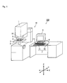
- a hardness tester 100 is a Vickers hardness tester, for example, and includes a tester main body 10, a controller 6, an operator 7, and a monitor 8, as shown in Figs. 1 and 2 .
- the tester main body 10 includes a hardness measurer 1 performing a measurement of hardness of a sample S; a sample stage 2 on which the sample S is placed; an XY stage 3 displacing the sample stage 2 in the horizontal direction; and an elevator mechanism 5 raising and lowering the sample stage 2 and the XY stage 3 in a vertical direction so as to focus on a surface of the sample S.
- the hardness measurer 1 is configured with an illuminating device 11 illuminating the surface of the sample S; a CCD camera 12 capturing an image of the surface of the sample S; and a turret 16.
- the turret 16 includes an indenter axis 14, which includes an indenter 141, and a field lens 15.
- the turret 16 is capable of switching between the indenter axis 14 and the field lens 15 by rotating.
- the illuminating device 11 shines a light to illuminate the surface of the sample S.
- the light shone by the illuminating device 11 reaches the surface of the sample S via a lens 1a, a half mirror 1d, a mirror 1e, and the field lens 15.
- the CCD camera 12 Based on reflected light input from the surface of the sample S via the field lens 15, the mirror 1e, the half mirror 1d, a mirror 1g, and a lens 1h, the CCD camera 12 obtains image data by capturing an image of the surface of the sample S as well as an indentation formed in the surface of the sample S by the indenter 141. The CCD camera 12 then outputs the image data to the controller 6 via a frame grabber 17, which is capable of simultaneously accumulating and storing a plurality of frames of image data. Thus, the CCD camera 12 is an image capturer.
- a plurality of indenter axes 14 are held on a bottom surface of the turret 16 and are disposed above the sample S by rotating the turret 16. Thereby, the indenter axis 14 is displaced toward the sample S placed on the sample stage 2 by a load mechanism (not shown in the drawings), which is driven in response to a control signal output by the controller 6.
- the indenter axis 14 thus presses the indenter 141 against the surface of the sample S with a predetermined test force, the indenter 141 being provided on a tip of the indenter axis 14 and having a quadrangular pyramid diamond tip.
- the field lenses 15 are collective lenses each configured with a different magnification.
- a plurality of the field lenses 15 are held on the bottom surface of the turret 16 and are disposed above the sample S by rotating the turret 16. Thereby, the light shone by the illuminating device 11 uniformly illuminates the surface of the sample S.
- the turret 16 is configured so as to be capable of switching to and disposing above the sample S any one of the plurality of indenter axes 14 and the plurality of field lenses 15, which are attached to the bottom surface of the turret 16, by rotating the turret 16 around a Z-axis direction.
- the indentation can be formed in the surface of the sample S by disposing the indenter axis 14 above the sample S, and the formed indentation can be observed by disposing the field lens 15 above the sample S.
- the sample S is placed on an upper surface of the sample stage 2 and fixed in place with a sample holder 2a.
- the XY stage 3 is manually driven by a user and displaces the sample stage 2 in a direction (X-axis or Y-axis direction) perpendicular to a displacement direction (Z-axis direction) of the indenter 141 (i.e., in the horizontal direction).
- the elevator mechanism 5 is manually driven by the user and raises and lowers the sample stage 2 and the XY stage 3 in the vertical direction (the Z-axis direction), thereby changing a relative distance between the sample stage 2 and the field lens 15.
- the operator 7 is configured with a keyboard 71 and a mouse 72.
- the operator 7 executes an input operation by the user when performing a hardness test.
- a predetermined input operation is performed by the operator 7, a predetermined operation signal corresponding to the input operation is output to the controller 6.
- the operator 7 enables the user to input a test condition value when carrying out the hardness test with the hardness tester 100.
- the input test condition value is transmitted to the controller 6.
- the test condition value is a value such as a material of the sample S, a test force (N) loaded on the sample S by the indenter 141, or a magnification power of the field lens 15, for example.
- the operator 7 enables the user to specify a test position where the indentation is to be formed, the test position being specified on the image of the surface of the sample S displayed on the monitor 8.
- the operator 7 is a test position specifier.
- the monitor 8 is configured with a display device such as an LCD, for example.
- the monitor 8 displays, for example, settings of the hardness test input on the operator 7, a layout for the test positions, results of the hardness test, and an image of the surface of the sample S as well as the indentation formed in the surface of the sample S captured by the CCD camera 12.
- the monitor 8 is a display.
- the controller 6 is configured to include a CPU (Central Processing Unit) 61, a RAM (Random Access Memory) 62, and a memory 63.
- the controller 6 performs operation control for performing a predetermined hardness test by executing a predetermined program stored in the memory 63.
- the CPU 61 retrieves a processing program stored in the memory 63, then opens and executes the processing program in the RAM 62.
- the CPU 61 thus performs overall control of the hardness tester 100.
- the RAM 62 opens the processing program executed by the CPU 61 in a program storage region within the RAM 62 and stores input data as well as processing results generated when the processing program is executed in a data storage region.
- the memory 63 includes, for example, a recording medium (not shown in the drawings) storing a program, data, and the like.
- the recording medium is configured with a semiconductor memory.
- the memory 63 stores various kinds of data allowing the CPU 61 to perform overall control of the hardness tester 100, various kinds of processing programs, and data processed by running the programs.
- the image data for the surface of the sample S is obtained by the CCD camera 12 (step S1). Specifically, the user places the sample S undergoing the hardness test on the sample stage 2 and fixes the sample S in place with the sample holder 2a. The user then rotates the turret 16 to dispose the field lens 15 above the sample S. The CCD camera 12 captures an image of the surface of the sample S via the field lens 15 to obtain the image data, then outputs the image data to the controller 6.
- step S2 the image of the surface of the sample S is displayed on the monitor 8 (step S2). Specifically, the CPU 61 displays an image G of the surface of the sample S on the monitor 8 based on the image data for the surface of the sample S output from the CCD camera 12 (see Fig. 6 ).
- the desired test positions are plotted on the image G (step S3).
- the user operates the operator 7 to specify desired test positions P1, P2, and so on where the indentation is to be formed, the test positions P1, P2, and so on being specified on the image G of the surface of the sample S displayed on the monitor 8 (see Fig. 7 ).
- the user operates the operator 7 to input an instruction that specification of the test positions is complete.
- an amount of offset in the XY direction (horizontal direction) between a center position O on the image G and the first test position P1 is displayed (step S4).
- the CPU 61 calculates the amount of offset in the XY direction between the first desired test position P1 and the center position O on the image G, which is the center position of the indenter 141 when forming the indentation in the sample S.
- the calculated amount of offset i.e., the amount by which the XY stage 3 must be displaced in order for the first test position P1 to be disposed in the center position O on the image G, is displayed on the monitor 8 (see Fig.
- the display indicates that the first test position P1 is offset "-5.00" in the X direction and "1.00” in the Y direction from the center position O on the image G.
- the CPU 61 is a controller calculating the amount of offset in the XY direction between the test positions P1, P2, and so on and the center position of the indenter 141 when forming the indentation, the amount of offset being calculated in conjunction with displacement of the XY stage 3, and displaying the calculated amount of offset on the monitor 8.
- the sample S is positioned such that the first test position P1 is disposed on the center position O on the image G (step S5).
- the user references the amount of offset in the XY direction displayed in step S4, then displaces the XY stage 3 in the XY direction.
- the CPU 61 continuously calculates the amount of offset in the XY direction between the first test position P1 and the center position O on the image G, then displays the calculated amount of offset in the XY direction on the monitor 8 in real time. Then, the user displaces the XY stage 3 until reaching a position where the amount of displacement in the XY direction is "0" in both the X and Y directions (see Fig. 9 ).
- the indentation is formed by the indenter 141 in the first test position P1 (step S6).
- the user rotates the turret 16 to dispose the indenter 141 above the sample S, then operates the operator 7 to input an indentation instruction.
- the CPU 61 receives the operation signal corresponding to the input operation from the operator 7, the load mechanism is driven, thereby lowering the indenter 141 and forming the indentation in the first test position P1.
- indentations are formed at the remaining test positions P2 and so on by repeating the processes of steps S4 to S6 such that indentations are formed at all of the test positions P1, P2, and so on.
- the image data for the surface of the sample S is obtained by the CCD camera 12 (step S7). Specifically, the user rotates the turret 16 to dispose the field lens 15 above the sample S. The CCD camera 12 captures the image of the surface of the sample S via the field lens 15 to obtain the image data, then outputs the image data to the controller 6.
- a degree of hardness of the sample S is calculated (step S8).
- the CPU 61 analyzes the image data for the surface of the sample S output from the CCD camera 12, then measures a length of diagonal lines in the indentation formed in the surface of the sample S. The CPU 61 then calculates the hardness value for the sample S based on the measured length of the diagonal lines.
- the hardness tester 100 includes the XY stage 3 displacing the sample stage 2 in the horizontal direction; the CCD camera 12 capturing the image of the surface of the sample S via the field lens 15; the monitor 8 displaying the image G of the surface of the sample S captured by the CCD camera 12; the operator 7 specifying the test positions P1, P2, and so on where the indentation is to be formed, the test positions P1, P2, and so on being specified on the image G displayed on the monitor 8; and the CPU 61 calculating the amount of offset in the XY direction between the test positions P1, P2, and so on and the center position of the indenter 141 when forming the indentation, the amount of offset being calculated in conjunction with displacement of the XY stage 3, and displaying the calculated amount of offset on the monitor 8.
- the amount of displacement necessary for the test positions P1, P2, and so on on the sample S to be disposed at the position of the indenter 141 forming the indentation can be displayed on the monitor 8 in real time in conjunction with displacement of the XY stage 3.
- the sample S can be positioned easily.
- the amount of offset in the XY direction between the desired test positions P1, P2, and so on and the center position O on the image G which is the center position of the indenter 141 when forming the indentation in the sample S, is calculated, then the calculated amount of offset is displayed on the monitor 8.
- the user may also be notified of proximity in a distance between the desired test positions P1, P2, and so on and the center position O on the image G through a control of the CPU 61.
- the amount of offset may be displayed in red and when the desired test positions P1, P2, and so on have moved away to a predetermined distance or greater from the center position O on the image G, the amount of offset may be displayed in blue.
- the monitor 8 is a notifier.
- a speaker (not shown in the drawings) or the like may be provided capable of sound output.
- the speaker is the notifier.
- the XY stage 3 may be vibrated when the desired test positions P1, P2, and so on are within the predetermined distance, and the load placed on the XY stage 3 during displacement may be increased when the desired test positions P1, P2, and so on have moved away to the predetermined distance or greater. In such a case, the XY stage 3 is the notifier.
- the combinations of color, sound, and feedback described above are merely exemplary and may be modified as appropriate within a range capable of notifying the user of the proximity.
- the CPU 61 notifies the user of the proximity in the distance between the desired test positions P1, P2, and so on and the center position of the indenter 141 (the center position O on the image G) using the notifier (the monitor 8, the speaker, the XY stage 3) based on the calculated amount of offset. Therefore, the user can recognize the proximity in the distance to the target while displacing the XY stage 3. Thus, the sample S can be positioned more easily.
- the user is notified of the proximity in the distance between the desired test positions P1, P2, and so on and the center position of the indenter 141 (the center position O on the image G).
- the user may be notified that the desired test positions P1, P2, and so on have reached the center position O on the image G through a control of the CPU 61.
- a character "0" displayed on the monitor 8 may be displayed in yellow.
- the character "0" may flash.
- the voice may be output saying "You have reached the target position.”
- the XY stage 3 may lock.
- the color, sound, and feedback described above are merely exemplary and may be modified as appropriate within a range capable of notifying the user that the target has been reached.
- the CPU 61 when the calculated amount of offset is zero, notifies the user that the desired test positions P1, P2, and so on have reached the center position of the indenter 141 using the notifier (the monitor 8, the speaker, the XY stage 3). Therefore, the user can recognize that the target has been reached while displacing the XY stage 3. Thus, the sample S can be positioned more easily.
- the user is notified of the proximity in the distance between the desired test positions P1, P2, and so on and the center position of the indenter 141 (the center position O on the image G).
- the user is notified that the desired test positions P1, P2, and so on have reached the center position O on the image G.
- the CPU 61 determines that the desired test positions P1, P2, and so on are moving away from the center position O on the image G based on the calculated amount of offset
- the user may be notified that displacement is in the opposite direction, for example, through a control of the CPU 61.
- the CPU 61 determines that the desired test positions P1, P2, and so on are moving away from the center position O on the image G, the amount of offset displayed on the monitor 8 may be displayed in green. Alternatively, the amount of offset may be erased from the display.
- the voice may be output saying "The target is in the opposite direction.”
- the load placed on the XY stage 3 during displacement may be increased.
- the color, sound, and feedback described above are merely exemplary and may be modified as appropriate within a range capable of notifying the user that displacement is in the opposite direction.
- the CPU 61 determines that the desired test positions P1, P2, and so on are moving away from the center position of the indenter 141 based on the calculated amount of offset, the CPU 61 notifies the user that displacement is in the opposite direction using the notifier (the monitor 8, the speaker, the XY stage 3). Therefore, the user can recognize that the XY stage 3 is being operated in the wrong direction while displacing the XY stage 3. Thus, the sample S can be positioned efficiently.
- the first through third modification examples may each be used in isolation or may be combined, as desired.
- the Vickers hardness tester was described to exemplify the hardness tester 100 in the above-described embodiment.
- the present invention is not limited to this.
- the present invention may be applied to a Knoop hardness tester having an indenter with a rhomboid pyramid diamond indenter, or to a Brinell hardness tester having a spherical indenter.
Landscapes
- Physics & Mathematics (AREA)
- Health & Medical Sciences (AREA)
- Life Sciences & Earth Sciences (AREA)
- Chemical & Material Sciences (AREA)
- Analytical Chemistry (AREA)
- Biochemistry (AREA)
- General Health & Medical Sciences (AREA)
- General Physics & Mathematics (AREA)
- Immunology (AREA)
- Pathology (AREA)
- Investigating Strength Of Materials By Application Of Mechanical Stress (AREA)
- Microscoopes, Condenser (AREA)
Applications Claiming Priority (1)
| Application Number | Priority Date | Filing Date | Title |
|---|---|---|---|
| JP2012070584A JP5977557B2 (ja) | 2012-03-27 | 2012-03-27 | 硬さ試験機 |
Publications (3)
| Publication Number | Publication Date |
|---|---|
| EP2645079A2 true EP2645079A2 (de) | 2013-10-02 |
| EP2645079A3 EP2645079A3 (de) | 2017-09-13 |
| EP2645079B1 EP2645079B1 (de) | 2023-02-22 |
Family
ID=47826956
Family Applications (1)
| Application Number | Title | Priority Date | Filing Date |
|---|---|---|---|
| EP13157368.5A Active EP2645079B1 (de) | 2012-03-27 | 2013-03-01 | Härtetester |
Country Status (4)
| Country | Link |
|---|---|
| US (1) | US9417171B2 (de) |
| EP (1) | EP2645079B1 (de) |
| JP (1) | JP5977557B2 (de) |
| CN (1) | CN103364292B (de) |
Families Citing this family (13)
| Publication number | Priority date | Publication date | Assignee | Title |
|---|---|---|---|---|
| JP6094457B2 (ja) * | 2013-11-05 | 2017-03-15 | 株式会社島津製作所 | 硬さ試験機 |
| CN104007014B (zh) * | 2014-06-18 | 2016-03-02 | 哈尔滨工业大学 | 微构件综合力学性能测试装置 |
| CN106546501A (zh) * | 2016-09-09 | 2017-03-29 | 上海尚材试验机有限公司 | 设有ccd图像采集系统的硬度计 |
| WO2018138943A1 (ja) | 2017-01-25 | 2018-08-02 | パナソニックIpマネジメント株式会社 | 剛性測定装置および剛性測定方法 |
| CN107132139A (zh) * | 2017-05-08 | 2017-09-05 | 吉林大学 | 悬挂式旋转快速定位原位压痕/变深弧形划痕测试装置 |
| JP7144267B2 (ja) * | 2018-10-03 | 2022-09-29 | 株式会社ミツトヨ | 硬さ試験機 |
| JP7141296B2 (ja) | 2018-10-03 | 2022-09-22 | 株式会社ミツトヨ | 硬さ試験機 |
| CN109900585A (zh) * | 2019-03-29 | 2019-06-18 | 河南省计量科学研究院 | 一种标准布氏硬度计 |
| CN109900584A (zh) * | 2019-03-29 | 2019-06-18 | 河南省计量科学研究院 | 一种布氏硬度计标准机 |
| JP7348040B2 (ja) | 2019-11-21 | 2023-09-20 | 株式会社ミツトヨ | 硬さ試験機及びプログラム |
| JP7303530B2 (ja) * | 2021-01-14 | 2023-07-05 | 国立大学法人東海国立大学機構 | 被測定物の硬さ測定装置および被測定物の硬さ測定方法 |
| US11768141B2 (en) | 2021-01-14 | 2023-09-26 | National University Corporation Tokai National Higher Education And Research System | Object hardness measuring device and method |
| CN119688510A (zh) * | 2025-02-27 | 2025-03-25 | 靖江新舟合金材料有限公司 | 一种合金生产用硬度测试装置 |
Citations (1)
| Publication number | Priority date | Publication date | Assignee | Title |
|---|---|---|---|---|
| JP2004286541A (ja) | 2003-03-20 | 2004-10-14 | Akashi Corp | 硬さ試験機 |
Family Cites Families (21)
| Publication number | Priority date | Publication date | Assignee | Title |
|---|---|---|---|---|
| JPS5093687A (de) * | 1973-12-20 | 1975-07-25 | ||
| JP2758760B2 (ja) * | 1992-01-17 | 1998-05-28 | 株式会社三協精機製作所 | 硬度測定方法 |
| WO1996039619A1 (en) * | 1995-06-06 | 1996-12-12 | Kla Instruments Corporation | Optical inspection of a specimen using multi-channel responses from the specimen |
| US6288780B1 (en) * | 1995-06-06 | 2001-09-11 | Kla-Tencor Technologies Corp. | High throughput brightfield/darkfield wafer inspection system using advanced optical techniques |
| US5616857A (en) * | 1996-01-25 | 1997-04-01 | Instron Corporation | Penetration hardness tester |
| WO1998008073A1 (en) * | 1996-08-23 | 1998-02-26 | Osteobiologics, Inc. | Handheld materials tester |
| US6641893B1 (en) * | 1997-03-14 | 2003-11-04 | Massachusetts Institute Of Technology | Functionally-graded materials and the engineering of tribological resistance at surfaces |
| JP2000146794A (ja) * | 1998-11-06 | 2000-05-26 | Nippon Steel Corp | ロックウェル硬度計 |
| US6247356B1 (en) * | 1999-03-30 | 2001-06-19 | Instron Corporation | Hardness tester |
| DE60231032D1 (de) * | 2001-04-12 | 2009-03-19 | Cellavision Ab | Verfahren in der mikroskopie und mikroskop, wobei teilbilder aufgezeichnet und in demselben koordinatensystem im puzzle-verfahren angeordnet werden, um eine präzise positionierung der mikroskopstufe zu ermöglichen |
| JP2003166923A (ja) * | 2001-11-30 | 2003-06-13 | Akashi Corp | 硬さ試験機及び硬さ試験方法 |
| CN1316417C (zh) * | 2002-10-18 | 2007-05-16 | 莱克公司 | 刻痕硬度测试系统 |
| US7121136B2 (en) * | 2002-12-25 | 2006-10-17 | Mitutoyo Corporation | Hardness testing apparatus |
| JP2004286542A (ja) * | 2003-03-20 | 2004-10-14 | Akashi Corp | 硬さ試験機 |
| JP4417121B2 (ja) * | 2004-01-19 | 2010-02-17 | 株式会社ミツトヨ | 被測定物の通り出し方法、及び表面性状測定装置 |
| CN101194263B (zh) * | 2005-06-13 | 2012-02-22 | 三路影像公司 | 利用显微镜成像装置再定位载片上样品中的目标的系统和方法 |
| US8201440B2 (en) * | 2008-11-21 | 2012-06-19 | Blake Brougher | Large diameter hardness tester |
| US8401339B1 (en) * | 2010-01-06 | 2013-03-19 | Marseille Networks, Inc. | Apparatus for partitioning and processing a digital image using two or more defined regions |
| JP2012078306A (ja) | 2010-10-06 | 2012-04-19 | Mitsutoyo Corp | 硬さ試験機 |
| JP5501189B2 (ja) | 2010-10-06 | 2014-05-21 | 株式会社ミツトヨ | 硬さ試験機 |
| JP5841379B2 (ja) | 2011-08-31 | 2016-01-13 | 株式会社ミツトヨ | 硬さ試験機 |
-
2012
- 2012-03-27 JP JP2012070584A patent/JP5977557B2/ja active Active
-
2013
- 2013-03-01 EP EP13157368.5A patent/EP2645079B1/de active Active
- 2013-03-14 US US13/828,164 patent/US9417171B2/en active Active
- 2013-03-27 CN CN201310101092.8A patent/CN103364292B/zh active Active
Patent Citations (1)
| Publication number | Priority date | Publication date | Assignee | Title |
|---|---|---|---|---|
| JP2004286541A (ja) | 2003-03-20 | 2004-10-14 | Akashi Corp | 硬さ試験機 |
Also Published As
| Publication number | Publication date |
|---|---|
| EP2645079B1 (de) | 2023-02-22 |
| CN103364292A (zh) | 2013-10-23 |
| US20130255362A1 (en) | 2013-10-03 |
| JP2013205020A (ja) | 2013-10-07 |
| EP2645079A3 (de) | 2017-09-13 |
| US9417171B2 (en) | 2016-08-16 |
| CN103364292B (zh) | 2017-06-23 |
| JP5977557B2 (ja) | 2016-08-24 |
Similar Documents
| Publication | Publication Date | Title |
|---|---|---|
| US9417171B2 (en) | Hardness tester | |
| EP2645080A2 (de) | Härtetester | |
| US8578284B2 (en) | Hardness testing device with a user interface for setting test locations | |
| JP6016620B2 (ja) | 硬さ試験機、及び硬さ試験方法 | |
| US9366609B2 (en) | Hardness tester and method for hardness test | |
| US9111332B2 (en) | Method and apparatus for hardness tester | |
| US20120087567A1 (en) | Hardness tester | |
| US10024774B2 (en) | Hardness test apparatus and hardness testing method | |
| US8887558B2 (en) | Hardness tester and testing method | |
| US20130047713A1 (en) | Hardness tester | |
| US10663381B2 (en) | Hardness tester and program | |
| JP2013050382A (ja) | 硬さ試験機 | |
| CN104458462A (zh) | 硬度试验机 | |
| US20170076436A1 (en) | Hardness test apparatus and hardness testing method | |
| CN104614263B (zh) | 硬度试验机 | |
| CN106525624B (zh) | 硬度测试设备和硬度测试方法 | |
| JP2016180737A (ja) | 硬さ試験機 | |
| JP6858038B2 (ja) | 硬さ試験機及びプログラム | |
| JP2002357524A (ja) | 硬度計 |
Legal Events
| Date | Code | Title | Description |
|---|---|---|---|
| PUAI | Public reference made under article 153(3) epc to a published international application that has entered the european phase |
Free format text: ORIGINAL CODE: 0009012 |
|
| AK | Designated contracting states |
Kind code of ref document: A2 Designated state(s): AL AT BE BG CH CY CZ DE DK EE ES FI FR GB GR HR HU IE IS IT LI LT LU LV MC MK MT NL NO PL PT RO RS SE SI SK SM TR |
|
| AX | Request for extension of the european patent |
Extension state: BA ME |
|
| PUAL | Search report despatched |
Free format text: ORIGINAL CODE: 0009013 |
|
| RIC1 | Information provided on ipc code assigned before grant |
Ipc: G01N 3/42 20060101AFI20170803BHEP |
|
| AK | Designated contracting states |
Kind code of ref document: A3 Designated state(s): AL AT BE BG CH CY CZ DE DK EE ES FI FR GB GR HR HU IE IS IT LI LT LU LV MC MK MT NL NO PL PT RO RS SE SI SK SM TR |
|
| AX | Request for extension of the european patent |
Extension state: BA ME |
|
| STAA | Information on the status of an ep patent application or granted ep patent |
Free format text: STATUS: REQUEST FOR EXAMINATION WAS MADE |
|
| 17P | Request for examination filed |
Effective date: 20171012 |
|
| RBV | Designated contracting states (corrected) |
Designated state(s): AL AT BE BG CH CY CZ DE DK EE ES FI FR GB GR HR HU IE IS IT LI LT LU LV MC MK MT NL NO PL PT RO RS SE SI SK SM TR |
|
| STAA | Information on the status of an ep patent application or granted ep patent |
Free format text: STATUS: EXAMINATION IS IN PROGRESS |
|
| 17Q | First examination report despatched |
Effective date: 20200221 |
|
| GRAP | Despatch of communication of intention to grant a patent |
Free format text: ORIGINAL CODE: EPIDOSNIGR1 |
|
| STAA | Information on the status of an ep patent application or granted ep patent |
Free format text: STATUS: GRANT OF PATENT IS INTENDED |
|
| INTG | Intention to grant announced |
Effective date: 20220901 |
|
| GRAS | Grant fee paid |
Free format text: ORIGINAL CODE: EPIDOSNIGR3 |
|
| GRAA | (expected) grant |
Free format text: ORIGINAL CODE: 0009210 |
|
| STAA | Information on the status of an ep patent application or granted ep patent |
Free format text: STATUS: THE PATENT HAS BEEN GRANTED |
|
| AK | Designated contracting states |
Kind code of ref document: B1 Designated state(s): AL AT BE BG CH CY CZ DE DK EE ES FI FR GB GR HR HU IE IS IT LI LT LU LV MC MK MT NL NO PL PT RO RS SE SI SK SM TR |
|
| REG | Reference to a national code |
Ref country code: GB Ref legal event code: FG4D |
|
| REG | Reference to a national code |
Ref country code: CH Ref legal event code: EP |
|
| REG | Reference to a national code |
Ref country code: DE Ref legal event code: R096 Ref document number: 602013083336 Country of ref document: DE |
|
| REG | Reference to a national code |
Ref country code: AT Ref legal event code: REF Ref document number: 1549807 Country of ref document: AT Kind code of ref document: T Effective date: 20230315 Ref country code: IE Ref legal event code: FG4D |
|
| REG | Reference to a national code |
Ref country code: LT Ref legal event code: MG9D |
|
| REG | Reference to a national code |
Ref country code: NL Ref legal event code: MP Effective date: 20230222 |
|
| REG | Reference to a national code |
Ref country code: AT Ref legal event code: MK05 Ref document number: 1549807 Country of ref document: AT Kind code of ref document: T Effective date: 20230222 |
|
| PG25 | Lapsed in a contracting state [announced via postgrant information from national office to epo] |
Ref country code: RS Free format text: LAPSE BECAUSE OF FAILURE TO SUBMIT A TRANSLATION OF THE DESCRIPTION OR TO PAY THE FEE WITHIN THE PRESCRIBED TIME-LIMIT Effective date: 20230222 Ref country code: PT Free format text: LAPSE BECAUSE OF FAILURE TO SUBMIT A TRANSLATION OF THE DESCRIPTION OR TO PAY THE FEE WITHIN THE PRESCRIBED TIME-LIMIT Effective date: 20230622 Ref country code: NO Free format text: LAPSE BECAUSE OF FAILURE TO SUBMIT A TRANSLATION OF THE DESCRIPTION OR TO PAY THE FEE WITHIN THE PRESCRIBED TIME-LIMIT Effective date: 20230522 Ref country code: NL Free format text: LAPSE BECAUSE OF FAILURE TO SUBMIT A TRANSLATION OF THE DESCRIPTION OR TO PAY THE FEE WITHIN THE PRESCRIBED TIME-LIMIT Effective date: 20230222 Ref country code: LV Free format text: LAPSE BECAUSE OF FAILURE TO SUBMIT A TRANSLATION OF THE DESCRIPTION OR TO PAY THE FEE WITHIN THE PRESCRIBED TIME-LIMIT Effective date: 20230222 Ref country code: LT Free format text: LAPSE BECAUSE OF FAILURE TO SUBMIT A TRANSLATION OF THE DESCRIPTION OR TO PAY THE FEE WITHIN THE PRESCRIBED TIME-LIMIT Effective date: 20230222 Ref country code: HR Free format text: LAPSE BECAUSE OF FAILURE TO SUBMIT A TRANSLATION OF THE DESCRIPTION OR TO PAY THE FEE WITHIN THE PRESCRIBED TIME-LIMIT Effective date: 20230222 Ref country code: ES Free format text: LAPSE BECAUSE OF FAILURE TO SUBMIT A TRANSLATION OF THE DESCRIPTION OR TO PAY THE FEE WITHIN THE PRESCRIBED TIME-LIMIT Effective date: 20230222 Ref country code: AT Free format text: LAPSE BECAUSE OF FAILURE TO SUBMIT A TRANSLATION OF THE DESCRIPTION OR TO PAY THE FEE WITHIN THE PRESCRIBED TIME-LIMIT Effective date: 20230222 |
|
| PG25 | Lapsed in a contracting state [announced via postgrant information from national office to epo] |
Ref country code: SE Free format text: LAPSE BECAUSE OF FAILURE TO SUBMIT A TRANSLATION OF THE DESCRIPTION OR TO PAY THE FEE WITHIN THE PRESCRIBED TIME-LIMIT Effective date: 20230222 Ref country code: PL Free format text: LAPSE BECAUSE OF FAILURE TO SUBMIT A TRANSLATION OF THE DESCRIPTION OR TO PAY THE FEE WITHIN THE PRESCRIBED TIME-LIMIT Effective date: 20230222 Ref country code: IS Free format text: LAPSE BECAUSE OF FAILURE TO SUBMIT A TRANSLATION OF THE DESCRIPTION OR TO PAY THE FEE WITHIN THE PRESCRIBED TIME-LIMIT Effective date: 20230622 Ref country code: GR Free format text: LAPSE BECAUSE OF FAILURE TO SUBMIT A TRANSLATION OF THE DESCRIPTION OR TO PAY THE FEE WITHIN THE PRESCRIBED TIME-LIMIT Effective date: 20230523 Ref country code: FI Free format text: LAPSE BECAUSE OF FAILURE TO SUBMIT A TRANSLATION OF THE DESCRIPTION OR TO PAY THE FEE WITHIN THE PRESCRIBED TIME-LIMIT Effective date: 20230222 |
|
| PG25 | Lapsed in a contracting state [announced via postgrant information from national office to epo] |
Ref country code: SM Free format text: LAPSE BECAUSE OF FAILURE TO SUBMIT A TRANSLATION OF THE DESCRIPTION OR TO PAY THE FEE WITHIN THE PRESCRIBED TIME-LIMIT Effective date: 20230222 Ref country code: RO Free format text: LAPSE BECAUSE OF FAILURE TO SUBMIT A TRANSLATION OF THE DESCRIPTION OR TO PAY THE FEE WITHIN THE PRESCRIBED TIME-LIMIT Effective date: 20230222 Ref country code: EE Free format text: LAPSE BECAUSE OF FAILURE TO SUBMIT A TRANSLATION OF THE DESCRIPTION OR TO PAY THE FEE WITHIN THE PRESCRIBED TIME-LIMIT Effective date: 20230222 Ref country code: DK Free format text: LAPSE BECAUSE OF FAILURE TO SUBMIT A TRANSLATION OF THE DESCRIPTION OR TO PAY THE FEE WITHIN THE PRESCRIBED TIME-LIMIT Effective date: 20230222 Ref country code: CZ Free format text: LAPSE BECAUSE OF FAILURE TO SUBMIT A TRANSLATION OF THE DESCRIPTION OR TO PAY THE FEE WITHIN THE PRESCRIBED TIME-LIMIT Effective date: 20230222 |
|
| REG | Reference to a national code |
Ref country code: CH Ref legal event code: PL |
|
| REG | Reference to a national code |
Ref country code: DE Ref legal event code: R097 Ref document number: 602013083336 Country of ref document: DE |
|
| PG25 | Lapsed in a contracting state [announced via postgrant information from national office to epo] |
Ref country code: SK Free format text: LAPSE BECAUSE OF FAILURE TO SUBMIT A TRANSLATION OF THE DESCRIPTION OR TO PAY THE FEE WITHIN THE PRESCRIBED TIME-LIMIT Effective date: 20230222 |
|
| REG | Reference to a national code |
Ref country code: BE Ref legal event code: MM Effective date: 20230331 |
|
| PG25 | Lapsed in a contracting state [announced via postgrant information from national office to epo] |
Ref country code: LU Free format text: LAPSE BECAUSE OF NON-PAYMENT OF DUE FEES Effective date: 20230301 |
|
| PLBE | No opposition filed within time limit |
Free format text: ORIGINAL CODE: 0009261 |
|
| STAA | Information on the status of an ep patent application or granted ep patent |
Free format text: STATUS: NO OPPOSITION FILED WITHIN TIME LIMIT |
|
| PG25 | Lapsed in a contracting state [announced via postgrant information from national office to epo] |
Ref country code: MC Free format text: LAPSE BECAUSE OF FAILURE TO SUBMIT A TRANSLATION OF THE DESCRIPTION OR TO PAY THE FEE WITHIN THE PRESCRIBED TIME-LIMIT Effective date: 20230222 |
|
| REG | Reference to a national code |
Ref country code: IE Ref legal event code: MM4A |
|
| GBPC | Gb: european patent ceased through non-payment of renewal fee |
Effective date: 20230522 |
|
| 26N | No opposition filed |
Effective date: 20231123 |
|
| PG25 | Lapsed in a contracting state [announced via postgrant information from national office to epo] |
Ref country code: SI Free format text: LAPSE BECAUSE OF FAILURE TO SUBMIT A TRANSLATION OF THE DESCRIPTION OR TO PAY THE FEE WITHIN THE PRESCRIBED TIME-LIMIT Effective date: 20230222 Ref country code: MC Free format text: LAPSE BECAUSE OF FAILURE TO SUBMIT A TRANSLATION OF THE DESCRIPTION OR TO PAY THE FEE WITHIN THE PRESCRIBED TIME-LIMIT Effective date: 20230222 Ref country code: LI Free format text: LAPSE BECAUSE OF NON-PAYMENT OF DUE FEES Effective date: 20230331 Ref country code: IE Free format text: LAPSE BECAUSE OF NON-PAYMENT OF DUE FEES Effective date: 20230301 Ref country code: FR Free format text: LAPSE BECAUSE OF NON-PAYMENT OF DUE FEES Effective date: 20230422 Ref country code: CH Free format text: LAPSE BECAUSE OF NON-PAYMENT OF DUE FEES Effective date: 20230331 |
|
| PG25 | Lapsed in a contracting state [announced via postgrant information from national office to epo] |
Ref country code: BE Free format text: LAPSE BECAUSE OF NON-PAYMENT OF DUE FEES Effective date: 20230331 |
|
| PG25 | Lapsed in a contracting state [announced via postgrant information from national office to epo] |
Ref country code: GB Free format text: LAPSE BECAUSE OF NON-PAYMENT OF DUE FEES Effective date: 20230522 |
|
| PG25 | Lapsed in a contracting state [announced via postgrant information from national office to epo] |
Ref country code: IT Free format text: LAPSE BECAUSE OF FAILURE TO SUBMIT A TRANSLATION OF THE DESCRIPTION OR TO PAY THE FEE WITHIN THE PRESCRIBED TIME-LIMIT Effective date: 20230222 |
|
| PG25 | Lapsed in a contracting state [announced via postgrant information from national office to epo] |
Ref country code: BG Free format text: LAPSE BECAUSE OF FAILURE TO SUBMIT A TRANSLATION OF THE DESCRIPTION OR TO PAY THE FEE WITHIN THE PRESCRIBED TIME-LIMIT Effective date: 20230222 |
|
| PG25 | Lapsed in a contracting state [announced via postgrant information from national office to epo] |
Ref country code: BG Free format text: LAPSE BECAUSE OF FAILURE TO SUBMIT A TRANSLATION OF THE DESCRIPTION OR TO PAY THE FEE WITHIN THE PRESCRIBED TIME-LIMIT Effective date: 20230222 |
|
| PG25 | Lapsed in a contracting state [announced via postgrant information from national office to epo] |
Ref country code: CY Free format text: LAPSE BECAUSE OF FAILURE TO SUBMIT A TRANSLATION OF THE DESCRIPTION OR TO PAY THE FEE WITHIN THE PRESCRIBED TIME-LIMIT; INVALID AB INITIO Effective date: 20130301 |
|
| PG25 | Lapsed in a contracting state [announced via postgrant information from national office to epo] |
Ref country code: HU Free format text: LAPSE BECAUSE OF FAILURE TO SUBMIT A TRANSLATION OF THE DESCRIPTION OR TO PAY THE FEE WITHIN THE PRESCRIBED TIME-LIMIT; INVALID AB INITIO Effective date: 20130301 |
|
| PG25 | Lapsed in a contracting state [announced via postgrant information from national office to epo] |
Ref country code: TR Free format text: LAPSE BECAUSE OF FAILURE TO SUBMIT A TRANSLATION OF THE DESCRIPTION OR TO PAY THE FEE WITHIN THE PRESCRIBED TIME-LIMIT Effective date: 20230222 |
|
| PGFP | Annual fee paid to national office [announced via postgrant information from national office to epo] |
Ref country code: DE Payment date: 20260319 Year of fee payment: 14 |