EP2644363A2 - Method of RTM molding - Google Patents
Method of RTM molding Download PDFInfo
- Publication number
- EP2644363A2 EP2644363A2 EP20130173648 EP13173648A EP2644363A2 EP 2644363 A2 EP2644363 A2 EP 2644363A2 EP 20130173648 EP20130173648 EP 20130173648 EP 13173648 A EP13173648 A EP 13173648A EP 2644363 A2 EP2644363 A2 EP 2644363A2
- Authority
- EP
- European Patent Office
- Prior art keywords
- resin
- reinforcing fiber
- distribution medium
- fiber substrate
- mold
- Prior art date
- Legal status (The legal status is an assumption and is not a legal conclusion. Google has not performed a legal analysis and makes no representation as to the accuracy of the status listed.)
- Granted
Links
Images


Classifications
-
- B—PERFORMING OPERATIONS; TRANSPORTING
- B29—WORKING OF PLASTICS; WORKING OF SUBSTANCES IN A PLASTIC STATE IN GENERAL
- B29C—SHAPING OR JOINING OF PLASTICS; SHAPING OF MATERIAL IN A PLASTIC STATE, NOT OTHERWISE PROVIDED FOR; AFTER-TREATMENT OF THE SHAPED PRODUCTS, e.g. REPAIRING
- B29C45/00—Injection moulding, i.e. forcing the required volume of moulding material through a nozzle into a closed mould; Apparatus therefor
- B29C45/0005—Injection moulding, i.e. forcing the required volume of moulding material through a nozzle into a closed mould; Apparatus therefor using fibre reinforcements
-
- B—PERFORMING OPERATIONS; TRANSPORTING
- B29—WORKING OF PLASTICS; WORKING OF SUBSTANCES IN A PLASTIC STATE IN GENERAL
- B29C—SHAPING OR JOINING OF PLASTICS; SHAPING OF MATERIAL IN A PLASTIC STATE, NOT OTHERWISE PROVIDED FOR; AFTER-TREATMENT OF THE SHAPED PRODUCTS, e.g. REPAIRING
- B29C70/00—Shaping composites, i.e. plastics material comprising reinforcements, fillers or preformed parts, e.g. inserts
- B29C70/04—Shaping composites, i.e. plastics material comprising reinforcements, fillers or preformed parts, e.g. inserts comprising reinforcements only, e.g. self-reinforcing plastics
- B29C70/28—Shaping operations therefor
- B29C70/40—Shaping or impregnating by compression not applied
- B29C70/42—Shaping or impregnating by compression not applied for producing articles of definite length, i.e. discrete articles
- B29C70/44—Shaping or impregnating by compression not applied for producing articles of definite length, i.e. discrete articles using isostatic pressure, e.g. pressure difference-moulding, vacuum bag-moulding, autoclave-moulding or expanding rubber-moulding
- B29C70/443—Shaping or impregnating by compression not applied for producing articles of definite length, i.e. discrete articles using isostatic pressure, e.g. pressure difference-moulding, vacuum bag-moulding, autoclave-moulding or expanding rubber-moulding and impregnating by vacuum or injection
-
- B—PERFORMING OPERATIONS; TRANSPORTING
- B29—WORKING OF PLASTICS; WORKING OF SUBSTANCES IN A PLASTIC STATE IN GENERAL
- B29C—SHAPING OR JOINING OF PLASTICS; SHAPING OF MATERIAL IN A PLASTIC STATE, NOT OTHERWISE PROVIDED FOR; AFTER-TREATMENT OF THE SHAPED PRODUCTS, e.g. REPAIRING
- B29C70/00—Shaping composites, i.e. plastics material comprising reinforcements, fillers or preformed parts, e.g. inserts
- B29C70/04—Shaping composites, i.e. plastics material comprising reinforcements, fillers or preformed parts, e.g. inserts comprising reinforcements only, e.g. self-reinforcing plastics
- B29C70/28—Shaping operations therefor
- B29C70/54—Component parts, details or accessories; Auxiliary operations, e.g. feeding or storage of prepregs or SMC after impregnation or during ageing
- B29C70/546—Measures for feeding or distributing the matrix material in the reinforcing structure
- B29C70/547—Measures for feeding or distributing the matrix material in the reinforcing structure using channels or porous distribution layers incorporated in or associated with the product
-
- B—PERFORMING OPERATIONS; TRANSPORTING
- B29—WORKING OF PLASTICS; WORKING OF SUBSTANCES IN A PLASTIC STATE IN GENERAL
- B29C—SHAPING OR JOINING OF PLASTICS; SHAPING OF MATERIAL IN A PLASTIC STATE, NOT OTHERWISE PROVIDED FOR; AFTER-TREATMENT OF THE SHAPED PRODUCTS, e.g. REPAIRING
- B29C70/00—Shaping composites, i.e. plastics material comprising reinforcements, fillers or preformed parts, e.g. inserts
- B29C70/04—Shaping composites, i.e. plastics material comprising reinforcements, fillers or preformed parts, e.g. inserts comprising reinforcements only, e.g. self-reinforcing plastics
- B29C70/28—Shaping operations therefor
- B29C70/54—Component parts, details or accessories; Auxiliary operations, e.g. feeding or storage of prepregs or SMC after impregnation or during ageing
- B29C70/546—Measures for feeding or distributing the matrix material in the reinforcing structure
- B29C70/548—Measures for feeding or distributing the matrix material in the reinforcing structure using distribution constructions, e.g. channels incorporated in or associated with the mould
-
- B—PERFORMING OPERATIONS; TRANSPORTING
- B29—WORKING OF PLASTICS; WORKING OF SUBSTANCES IN A PLASTIC STATE IN GENERAL
- B29C—SHAPING OR JOINING OF PLASTICS; SHAPING OF MATERIAL IN A PLASTIC STATE, NOT OTHERWISE PROVIDED FOR; AFTER-TREATMENT OF THE SHAPED PRODUCTS, e.g. REPAIRING
- B29C70/00—Shaping composites, i.e. plastics material comprising reinforcements, fillers or preformed parts, e.g. inserts
- B29C70/68—Shaping composites, i.e. plastics material comprising reinforcements, fillers or preformed parts, e.g. inserts by incorporating or moulding on preformed parts, e.g. inserts or layers, e.g. foam blocks
Definitions
- the present invention relates to improvement of a method of Resin Transfer Molding (hereinafter, referred to as "RTM") for molding a structural material of a fiber reinforced plastic (hereinafter, referred to as "FRP”), and specifically, to a method of RTM molding in which it is possible to mold a thick material, and further, it is possible to improve a quality of surface property or to increase a fiber volume content (hereinafter, also referred to as "Vf”) of an FRP molded material to be molded.
- RTM Resin Transfer Molding
- FRP fiber reinforced plastic
- Vf fiber volume content
- FRP has been used in various fields, as a method for producing an FRP structural material, general is a so-called prepreg/autoclave molding method wherein, after a preform having a shape of a structural material to be molded is formed beforehand by prepregs, the preform is cured in an autoclave set at a predetermined condition in temperature and pressure.
- RTM molding is paid attention to in order to reduce the production cost, and this method is developed gradually.
- Many methods are proposed as RTM molding methods for producing panels and beam materials which are structural members for air planes or architecture requiring high strength, lightweight and low cost or for producing FRP molded products such as outer panels of vehicles.
- peel plys/resin distribution media are disposed on both surfaces of a reinforcing fiber substrate comprising a laminate of reinforcing fiber materials, the whole thereof is covered with a bag material, and a resin injection gate and an evacuation gate for reducing a pressure are provided relative to the inside covered with the bag material.
- a resin is injected from the resin injection gate while being reduced in pressure by evacuating the inside of the bag material through the evacuation gate, and basically, the resin is flown from the upper surface side to the lower surface side of the reinforcing fiber substrate, or from the lower surface side to the upper surface side, to impregnate the resin into the reinforcing fiber substrate.
- the resin is cured at a room temperature or under a heated atmosphere condition, and after curing, the molded product is taken out from the mold by removing the bag material.
- the permeability corresponds to a distance (thickness) of resin impregnation into the substrate.
- the above-described resin distribution medium is formed as a member having a relatively large surface irregularity with a low resistance for gas permeation in order to increase the resin distribution property.
- the resin distribution media having such a relatively large surface irregularity are disposed on both surfaces of the reinforcing fiber substrate and the molding is carried out in this condition, the relatively large surface irregularity of the resin distribution medium is reflected to the design surface which is one surface of the molded product. As a result, the designability is damaged and an irregularity is formed on the surface of the molded product, and therefore, there is a problem that the properties such as aerodynamic property decrease.
- the degree of the irregularity of the resin distribution medium affects the resin distribution and gas permeation performances
- the irregularity of the resin distribution medium for improving resin distribution and gas permeation performances (a relatively large irregularity)
- the irregularity of the resin distribution medium for improving the surface property of the molded product (a relatively small irregularity) are in a relationship opposite to each other. Therefore, in the conventional method wherein substantially same resin distribution media are disposed on both surfaces of a reinforcing fiber substrate, it is difficult to achieve both of increase of the resin impregnation property and improvement of the surface property of a molded product, and it becomes particularly difficult in the molding using a thick reinforcing fiber substrate.
- a reinforcing fiber substrate is placed on a mold and a resin distribution medium is disposed at a position opposite to the mold, a resin injection port and an evacuation port are disposed, they are covered with a bag material from the upper side, and a matrix resin is injected at a condition where the inside of a cavity is reduced in pressure by evacuation.
- the flowing-in route of the resin into the substrate is formed as a route in which the resin is distributed mainly from the injection port along the surface direction of the substrate disposed in the mold and the distributed resin is impregnated in the thickness direction of the substrate.
- the Vf of the reinforcing fibers is, for example, 45% and the gap between reinforcing fibers is relatively great, because the fiber volume content of the final molded product becomes low although a good resin impregnation property can be obtained, only a product having poor strength and lightweight property can be obtained. Namely, the resin impregnation property and the fiber volume content Vf are in a relationship opposite to each other, and it is difficult to achieve both improvement of the resin impregnation property and increase of the fiber volume content together. Moreover, although it is preferred depending on a molded product to control the fiber volume content from the necessity of stabilization of the quality, it is also difficult to satisfy such a requirement.
- the reinforcing fiber substrate is formed as a laminate of a plurality of reinforcing fiber materials in order to obtain an FRP molded product with a predetermined thickness, as to the thickness direction, that is, as to the direction perpendicular to the lamination surface in the reinforcing fiber material laminate, the resistance against the resin flow is generally high, and there is a limit in the reaching distance of the resin being impregnated in the thickness direction of the substrate.
- an object of the present invention is to provide a method of RTM molding (method for producing an FRP) which can solve the above-described various problems in the conventional methods, which can mold even a thick FRP structural material with a good resin impregnation property, and which can realize improvement of the surface quality, increase of the lightweight property and achievement of an excellent strength.
- a method of RTM molding according to the present invention wherein a reinforcing fiber substrate is placed in a mold, resin distribution media each exhibiting a resin flow resistance lower than a resin flow resistance of the reinforcing fiber substrate are placed on both surfaces of the reinforcing fiber substrate, and after a pressure in the mold is reduced by evacuation, a resin is injected into the mold through the resin distribution media to impregnate the reinforcing fiber substrate with the resin injected, is characterized in that a resin flow resistance of a first resin distribution medium placed on a first surface of the reinforcing fiber substrate is set lower than a resin flow resistance of a second resin distribution medium placed on a second surface of the reinforcing fiber substrate, and the evacuation is carried out through the second resin distribution medium while the resin is injected into the first resin distribution medium to impregnate the reinforcing fiber substrate with the resin injected (a first method).
- the resin flow resistance can be determined by measuring a gas permeation resistance and determining it as a value corresponding to the measured gas permeation resistance.
- the reinforcing fiber substrate may be a single layer or may be formed as a laminate of a plurality of reinforcing fiber materials
- the method of RTM molding according to the present invention is suitable particularly for molding of a thick product, namely, for molding for impregnating a resin into a thick reinforcing fiber substrate
- the target of the present invention is mainly a case where a reinforcing fiber substrate comprising a laminate of a plurality of reinforcing fiber materials is used.
- the resin flow resistance of the above-described second resin distribution medium is set lower than the resin flow resistance of the above-described reinforcing fiber substrate.
- the resin flow resistance of the above-described first resin distribution medium is set at 1/3 of the resin flow resistance of the reinforcing fiber substrate or less, because the resin can be distributed into the medium quickly. Further, more preferably, it is set at 1/10 or less to distribute the resin more quickly.
- the distribution property of the resin injected into the first resin distribution medium in the surface direction of the reinforcing fiber substrate is ensured to be sufficiently high, the resin injected into the first resin distribution medium is quickly impregnated in the thickness direction of the reinforcing fiber substrate while the resin is distributed quickly in a direction along the surface. Under such a condition where the resin flow resistance of the first resin distribution medium and the resin flow resistance of the second resin distribution medium are satisfied, the large/small relationship is given to the resin flow resistance of the first resin distribution medium and the resin flow resistance of the second resin distribution medium.
- a peel ply capable of being removed together with a resin distribution medium after molding is interposed between at least one resin distribution medium and the reinforcing fiber substrate.
- the resin distribution medium can be easily delaminated.
- at least one resin distribution medium may be left in the molded product without delaminating it from the molded product. In this case, the peel ply is not necessary for the side where the resin distribution medium is left.
- a method may be employed wherein a porous sheet is interposed between at least one resin distribution medium and the reinforcing fiber substrate.
- This porous sheet has a function different from that of the above-described peel ply, and it is a sheet for suppressing a transfer of the irregularity of the resin distribution medium to the reinforcing fiber substrate side while maintaining the resin distribution function of the resin distribution medium. Therefore, the sheet is preferably disposed on the design surface side of the molded product.
- At least one resin distribution medium may be formed by providing a groove as a resin flow path on an inner surface of the mold. In this case, even if a separate resin distribution medium is not made, it is possible to use the inner surface of the mold itself as a resin distribution medium.
- a method can be employed wherein, in a case where at least two resin injection gates are disposed above the first resin distribution medium, the resin injection is carried out simultaneously from at least two resin injection gates adjacent to each other, or from all resin injection gates. Since the evacuation through the second resin distribution medium as well as the resin injection are carried out simultaneously while the quick resin impregnation is achieved, the generation of resin non-impregnation portions can be prevented.
- a method of RTM molding according to the present invention is characterized in that a reinforcing fiber substrate is placed in a mold, a resin distribution medium exhibiting a resin flow resistance lower than a resin flow resistance of the reinforcing fiber substrate is placed on a surface of the reinforcing fiber substrate opposite to the mold, a degasification medium comprising a gas permeation film and a gas permeable substrate is provided between the reinforcing fiber substrate and the mold, a resin is injected into the mold through the resin distribution medium after a pressure in the mold is reduced by evacuation, and the resin injected is impregnated into the reinforcing fiber substrate by evacuating the resin injected from a degasification space formed between the gas permeation film and the mold (a second method).
- the above-described reinforcing fiber substrate comprises, for example, a laminate of reinforcing fiber materials.
- the above-described gas permeation film has a releasability capable of being delaminated from a molded product after molding.
- At least two resin injection gates are disposed above the resin distribution medium, and resin injection is carried out simultaneously from at least two resin injection gates adjacent to each other, or from all resin injection gates.
- At least one evacuation route is provided in the mold in addition to an evacuation route from the degasific ation space formed between the gas permeation film and the mold.
- the resin is injected into the first resin distribution medium having a lower resin flow resistance, and the injected resin is quickly impregnated into the reinforcing fiber substrate in the thickness direction while the resin is distributed quickly and broadly in a direction along the first surface of the reinforcing fiber substrate. Then, basically the inside of the mold is reduced in pressure by evacuation via the second resin distribution medium having a higher resin flow resistance, and the above-described injected resin is impregnated into the reinforcing fiber substrate having an evacuated and pressure-reduced condition.
- the resin flow resistance (gas permeation resistance) of the second resin distribution medium is suppressed sufficiently low as compared with the resin flow resistance (gas permeation resistance) of the reinforcing fiber substrate although it is higher than the resin flow resistance (gas permeation resistance) of the first resin distribution medium, it is suppressed to reduce the vacuum degree in the substrate by deterioration of gas permeation from the reinforcing fiber substrate, and a quick resin impregnation can be ensured. Therefore, even for a thick reinforcing fiber substrate, a sufficiently good resin impregnation can be ensured.
- the second resin distribution medium can be formed as a medium with a small irregularity as compared with the first resin distribution medium, and even if a transfer of the surface form of this second resin distribution medium to the surface of a molded product occurs, the degree of the irregularity on the surface of the molded product ascribed to the transfer can be suppressed small. Therefore, by setting this surface side to be a design surface side, a desirable design surface of the molded product having a small irregularity can be obtained.
- the resin impregnation can be supplemented for a portion in which the resin is hardly impregnated into the reinforcing fiber substrate sufficiently, that is, for a portion of the second surface side, and it becomes possible to impregnate the resin sufficiently over the entire region of the reinforcing fiber substrate in the thickness direction.
- the resin impregnation in the thickness direction of the reinforcing fiber substrate is carried out mainly by the impregnation from the first resin distribution medium side, and a lack of the impregnation is supplemented by the impregnation from the second resin distribution medium side.
- the resin impregnation is supplemented, and voids pushed out from the first resin distribution medium side by the impregnated resin are pushed out at a relatively slow speed toward side portions, that is, in a direction along the second surface of the reinforcing fiber substrate, without being enclosed in the reinforcing fiber substrate by the resin impregnated from the second resin distribution medium side.
- the aforementioned method of RTM molding according to the present invention (the second method) is effective for the following cases namely, in a case where a flatness of a molded surface (a design surface) at the mold side is required further strongly, and in a molding where a resin impregnation into a thick and broad-area reinforcing fiber substrate is required, in particular, a degasification medium comprising a gas permeation film and a gas permeable substrate can be provided between the reinforcing fiber substrate and the surface of the mold as means for always effectively operating the degasification route from any portion of the mold surface.
- the gas permeation film for example, preferably has fine holes on the surface and forms a flat surface. If such a film is employed, together with using a thin and small-irregularity substrate as the above-mentioned gas permeable substrate, the surface quality of a molded product can be improved.
- the present invention also provides the following method of RTM molding from the viewpoint of high Vf molding.
- the method of RTM molding according to the present invention wherein a reinforcing fiber substrate is placed in a mold, a resin injection line and an evacuation line each communicating with an inside of the mold are provided, a pressure in the mold is reduced by evacuation and a resin is injected into the mold and impregnated into the reinforcing fiber substrate to form an FRP molded material, is characterized in that , after the resin is impregnated into the reinforcing fiber substrate so as to achieve a fiber volume content lower than a target fiber volume content of the FRP molded material, the injection of resin is stopped, and thereafter, evacuation of resin is continued until reaching the target fiber volume content (a third method).
- a method can be employed wherein, after the injection of resin is stopped, at least one line of resin injection lines is changed to an evacuation line, and the evacuation of resin is continued until reaching the target fiber volume content.
- the above-described target fiber volume content is preferably, for example, in a range of 55 to 65% to achieve a high Vf.
- the above-described fiber volume content lower than the target fiber volume content is preferably, for example, in a range of 45 to 60%.
- the resin impregnation property is required to be further increased, it is preferably in a range of 45 to 55%.
- the above-described reinforcing fiber substrate can be formed as a preform having a fiber volume content, which is a rate of a volume of reinforcing fibers relative to a bulk volume of the reinforcing fiber substrate, lower than the target fiber volume content.
- a woven fabric preformed at an arbitrary fiber volume content within a range lower than the target fiber volume content, or a laminate can be used as the reinforcing fiber substrate.
- the laminate may be formed by laminating layers of reinforcing fibers by an arbitrary number, and a structure, where reinforcing fiber layers are bonded to each other, is more preferable because a stability is given to the fiber volume content.
- the determination whether reaching the target fiber volume content or not can be carried out, for example, by measurement of the thickness of the reinforcing fiber substrate, and it may be determined whether an excessive resin is evacuated and removed by a predetermined amount or not by measuring this thickness during the continuation of the resin evacuation.
- a method can be employed wherein an injection amount of resin corresponding to the fiber volume content lower than the target fiber volume content is preset, and the injection of resin is stopped at the time reaching the injection amount preset. Further, a method can be employed wherein an evacuation amount for reaching the target fiber volume content is preset relative to an injection amount of resin, and the evacuation of resin is stopped at the time reaching the evacuation amount preset.
- At least one layer of the reinforcing fiber substrate comprises a carbon fiber layer, in order to obtain a high-strength and lightweight FRP molded material.
- This carbon fiber layer can be formed as a woven fabric, for example, a unidirectional woven fabric in which carbon fibers are oriented unidirectionally.
- the third method because first the resin is impregnated into the reinforcing fiber substrate so that the fiber volume content becomes lower than the target fiber volume content of the FRP molded material, the porosity is high, the resin is impregnated sufficiently over the entire area of the reinforcing fiber substrate, and at that time, generation of resin non-impregnated portions can be prevented. After this resin impregnation, the resin injection is stopped, and thereafter, by the time when the resin is cured, the evacuation of resin is continued until reaching the target fiber volume content, and excessive resin is evacuated from the inside of the reinforcing fiber substrate, thereby achieving a target high Vf of the molded material.
- the present invention also provides the following method of RTM molding as another method for solving the aforementioned problems.
- the method of RTM molding according to the present invention is characterized in that a plurality of reinforcing fiber materials are laminated in a mold to form a reinforcing fiber material laminate, and a resin is impregnated into the reinforcing fiber material laminate by injecting a resin in a direction from an end surface of the reinforcing fiber material laminate along a laminate surface while reducing a pressure in the mold by evacuation (a fourth method).
- the resin is injected from the end surface of the reinforcing fiber material laminate mainly into a portion between layers of the reinforcing fiber materials, and the resin injected is impregnated into respective reinforcing fiber materials.
- the resin is injected from the end surface of the reinforcing fiber material laminate in the direction along the laminate surface, first, the resin is injected quickly into a portion between the layers of the reinforcing fiber materials forming the reinforcing fiber material laminate, which is low in flow resistance, and thereafter, the resin is impregnated from the portion between the layers in the thickness direction of the respective reinforcing fiber materials, namely, in the lamination direction of the reinforcing fiber materials, and therefore, the matrix resin can be quickly injected and impregnated over the entire reinforcing fiber material laminate.
- the limit in thickness such as a conventional limit does not exist, and the aforementioned problems can be solved at a time.
- the resin flow resistance in the direction parallel to the surfaces of the reinforcing fiber materials is about 1/5-1/10 of the resin flow resistance in the direction perpendicular to the surfaces of the reinforcing fiber materials, according to experiment, although it is different depending on the kinds of the reinforcing fiber material and the resin, and the resin distribution speed in the direction parallel to the surfaces of the reinforcing fiber materials is very fast as compared with that in the perpendicular direction.
- the molding condition is considered that the distance required for progressing the resin between the layers should be about 600 mm or less.
- the restriction in thickness of the reinforcing fiber material laminate substantially does not exist, and the molding can be well carried out up to a thick molded material.
- the irregularity of the resin distribution medium is not transferred, the surface property can be improved and a great cost down can be achieved by saving the processes for preparing and removing the resin distribution medium.
- the gross length of the reinforcing fiber material laminate in a case where there is a bend or/and a curve, it is a total length along the shape
- the resin injection from the above-described end surface into the portions between layers.
- this length is more than 600 mm, the resin is hardly impregnated and there is a fear that a resin non-impregnated portion is generated.
- the length is 300 mm or less, the resin impregnation becomes possible in a shorter time, and such a condition is more preferable.
- the resin viscosity at a temperature for liquid resin injection is maintained in a range of 10 to 1500 mPa ⁇ s during a time from starting of the resin impregnation to expiration of one hour, a resin impregnation in a short period of time is possible.
- the resin viscosity is less than 10 mPa ⁇ s, because the resin viscosity is too low, although the resin is quickly permeated in the portions between layers in the direction along the laminate surface, particularly in a case where the reinforcing fiber material is formed from a strand and the like, because the resin impregnation from the portion around the strand toward the inside of the strand progresses substantially simultaneously, a resin non-impregnated portion is liable to occur in the strand.
- the resin viscosity at the temperature of liquid resin injection is maintained in a range of 10 to 1500 mPa ⁇ s during the time from starting of the resin impregnation to expiration of one hour.
- the sectional shape of the reinforcing fiber material laminate is not particularly restricted, and it may be a rectangular, C-type, I-type, L-type, Z-type, T-type, J-type or hat shape, other than a flat plate shape.
- the skin material is frequently formed in a simple flat plate shape but the stringer material is frequently formed in a relatively complicated shape, and in such a case, the present invention is suitably applied particularly to the part for forming the stringer material.
- the present invention is suitable particularly for molding of this part for forming the stringer material.
- the resin is injected from the end surface of the part for forming the stringer material of the laminate mainly into portions between layers of the respective reinforcing fiber materials, the resin injected is impregnated into the entire part for forming the stringer material.
- these part for forming the stringer material and part for forming the skin material may be molded integrally.
- the resin is injected from the end surface of the part for forming the stringer material, restriction in thickness of stringer material does not exist, and because it is not necessary to dispose a resin distribution medium, an improvement ofsurface property, and a great cost down due to saving of the preparing operation and the removing operation of the resin distribution medium, can be achieved.
- a method can be employed wherein, for the part for forming the skin material, the resin is impregnated in the thickness direction while distributed in the direction along the surface of the part for forming the skin material via a resin distribution medium, and a reinforcing panel formed from the skin material and the stringer material is molded integrally.
- a method can be employed wherein an upper mold provided with a resin distribution medium or a resin flow path groove is further disposed on the end surface of the reinforcing fiber material laminate.
- Fig. 1 is a schematic vertical sectional view of a molding apparatus used for a method of RTM molding according to a first embodiment of the present invention.
- a mold 1 forming a base is made, for example, from a stainless steel or an aluminum alloy, or another metal for mold or an FRP, and formed in, for example, a flat-plate like shape.
- the shape of the mold 1 is processed depending on the shape of a desired molded product, and is not particularly restricted.
- a breather 2 is disposed on mold 1 as a second resin distribution medium.
- the "breather” has a resin flow resistance lower than a flow resistance of a resin flowing in a reinforcing fiber substrate although its resin flow resistance is not low as the flow resistance of the aforementioned conventional resin distribution medium.
- the surface irregularity (surface roughness) of breather 2 is preferably 1.3 times or less of the surface irregularity (surface roughness) of the reinforcing fiber substrate.
- a surface mat a plain weave woven fabric or a mesh woven fabric comprising glass fibers or carbon fibers which are reinforcing fibers and having a low weight (100 g/m 2 or less), or a woven fabric or a knit fabric comprising synthetic fibers and having a large denier (200 denier or more), is preferred.
- a peel ply 3a is placed on breather 2. Peel ply 3a is laid in order to easily remove media and the like from a molded material, and as peel ply 3a, for example, a woven fabric having a releasing function such as a nylon taffeta is used.
- reinforcing fiber substrate 4 is placed on peel ply 3a.
- reinforcing fiber substrate 4 is formed as a laminate of a plurality of reinforcing fiber materials, in particular, a plurality of reinforcing fiber woven fabrics.
- the present invention is suitable particularly for the molding using such a thick reinforcing fiber substrate 4 laminated with a plurality of reinforcing fiber materials.
- the present invention can be applied, and also in such a case, the present invention is suitable particularly for the molding using a thick reinforcing fiber substrate.
- a first resin distribution medium 5 is placed on reinforcing fiber substrate 4 via peel ply 3b.
- First resin distribution medium 5 has an irregularity on the surface, and in this embodiment, the medium has a resin flow resistance of 1/10 or less of the resin flow resistance of reinforcing fiber substrate 4 (reinforcing fiber material laminate).
- a large/small relationship in resin flow resistance is given between first resin distribution medium 5 and breather 2 as a second resin distribution medium, and the resin flow resistance of breather 2 is set higher than the resin flow resistance of first resin distribution medium 5.
- first resin distribution medium 5 concretely, a mesh woven fabric made of polyethylene or polypropylene resin and having a mesh size of #400 or less is preferred. As the result of such a disposition, first resin distribution medium 5 is disposed relative to the first surface of reinforcing fiber substrate 4, and breather 2 as the second resin distribution medium is disposed relative to the second surface at the opposite side.
- bag material 8 comprises a gas-tight material for forming a pressure-reduced cavity, for this bag material 8, in consideration of thermal resistance, etc., for example, a nylon film is preferably used.
- a resin injection gate 6c is provided relatively to first resin distribution medium 5 in the inside covered with bag material 8, and evacuation gates 6a, 6b for reducing the pressure of the inside by evacuation are provided relatively to breather 2 provided as the second resin distribution medium.
- These gates 6a, 6b, 6c are formed, for example, by using C channel materials made of aluminum and the like, and these channel materials are connected to external members via plastic tubes.
- a sealant 7 made of a synthetic rubber with a high adhesive property is interposed between the edge portion of bag material 8 and mold 1, and by sealing therebetween, flowing in of air from outside is prevented in order to maintain a pressure-reduced condition of the inside of bag material 8.
- a thermoplastic resin 10 prepared as an FRP matrix resin to be impregnated is stored in a resin pot 12 made of a plastic, and by opening a valve 9 at an appropriate timing, the resin is injected via resin injection gate 6c.
- the inside of the cavity covered with bag material 8 is maintained at a pressure-reduced condition by a vacuum pump 11 via evacuation gates 6a, 6b.
- bag material 8 is a double bag having a first bag material and a second bag material covering the first bag material, an air leakage can be prevented, and as a result, the fiber volume content (Vf) of reinforcing fibers can be increased.
- bag material 8 is a single bag
- the air leakage can be prevented by disposing sealant 7 at the outer edge portion as a parallel double disposition style, and an effect similar to that due to the double bag can be obtained.
- the amount used for sub materials and the attachment time can be reduced rather than those in the double bag system, and there ir a merit capable of performing the molding more inexpensively.
- ply 3b/resin distribution medium 5 are disposed on reinforcing fiber substrate 4 and peel ply 3a/breather 2 are disposed under the reinforcing fiber substrate 4 as in a conventional molding, it may be carried out that, after molding without disposing peel ply 3a, breather 2 is left in the molded material as it is.
- the laminate having a structure shown in Fig. 1 is placed on mold 1 (a tool), and the whole of the materials and members including resin injection gate 6c disposed at the upper side and evacuation gates 6a, 6b disposed at the lower side is covered with bag material 8.
- bag material 8 In this state, when the resin is injected from resin injection gate 6c while the inside of bag material 8 is reduced in pressure by the evacuation through evacuation gates 6a, 6b, while matrix resin 10 is quickly distributed in first resin distribution medium 5 in a direction along the upper surface of reinforcing fiber substrate 4, the resin flows in a direction from the upper surface toward the lower surface and is impregnated into the reinforcing fiber substrate 4.
- the resin is cured under a room temperature or a heated atmosphere, and thereafter, bag material 8 is delaminated and the molded material is released from the mold. Thereafter, peel plies 3a, 3b, resin distribution medium 5 and breather 2 are released and removed from the molded product.
- breather 2 may be left in the molded product as it is.
- first resin distribution medium 5 because the resin flow resistance of first resin distribution medium 5 is set low, the resin injected into the first resin distribution medium 5 is quickly impregnated into reinforcing fiber substrate 4 in the thickness direction while the resin is distributed in the direction along the first surface of the reinforcing fiber substrate 4 quickly and sufficiently broadly.
- bag material 8 is evacuated via breather 2 provided as the second resin distribution medium in order to reduce the pressure in the bag material 8, because the resin flow resistance (gas permeation resistance) of breather 2 is suppressed sufficiently low as compared with the resin flow resistance (gas permeation resistance) of reinforcing fiber substrate 4 although it is higher than the resin flow resistance (gas permeation resistance) of first resin distribution medium 5, the reduction of vacuum degree in the substrate due to the deterioration of gas permeability from the reinforcing fiber substrate can be suppressed, and a quick resin impregnation property can be ensured. Therefore, even for a thick reinforcing fiber substrate 4, a sufficiently good resin impregnation property from the side of first resin distribution medium 5 can be ensured.
- the breather 2 can be formed as a medium having a small irregularity as compared with the first resin distribution medium 5. Therefore, even if the surface pattern of such a breather 2 is transferred to the surface of a molded product, the degree of the irregularity of the surface of the molded product due to the transfer can be suppressed small. Namely, while a good resin impregnation property can be ensured, the irregularity of the surface of the molded product at the second resin distribution medium side can be suppressed small. By setting this surface side of the molded product having a small irregularity at a design surface side, a molded product having a desirable surface property can be obtained. Namely, it is possible to extinguish the traces of the medium which have been present in the tool surface side of the molded product by curing of the resin in the conventional method.
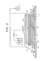
- Fig. 2 is a schematic vertical sectional view of a molding apparatus according to a second embodiment of the present invention, and Fig. 2 shows an embodiment wherein, instead of the breather, a resin distribution medium 5a and a porous sheet 20 are disposed on one surface of the reinforcing fiber substrate.
- Fig. 3 is a schematic vertical sectional view of a molding apparatus according to a third embodiment of the present invention, and Fig. 3 shows an embodiment wherein, instead of the resin distribution medium disposed on the surface of the mold in Fig. 2 , the surface of the mold itself is formed as a resin distribution medium of the resin injection side by processing grooves on the mold.
- the apparatus shown in Fig. 1 will be explained.
- Symbol 20 indicates a porous sheet, and as the material of porous sheet 20, it is preferred to use a metal thin plate material (aluminum or stainless steel material), a steel punching metal with a thickness of 0.1 mm or more, a resin film with a thickness of 0.2 mm or more (a nylon, polyester, polyethylene, polypropylene or polyimide film), or an FRP sheet with a thickness of 0.2 mm or more.
- a metal thin plate material aluminum or stainless steel material
- a steel punching metal with a thickness of 0.1 mm or more
- a resin film with a thickness of 0.2 mm or more a nylon, polyester, polyethylene, polypropylene or polyimide film
- an FRP sheet with a thickness of 0.2 mm or more.
- the hole is preferred to be circular-type from the viewpoint of processing, the shape is not particularly limited.
- the hole diameter is preferably 3 mm or less, and more preferably 15 mm or less.
- the arrangement of the holes may be either random or regular. Although a desirable pitch of the holes varies depending on the specification of the reinforcing fiber substrate to be used, it is preferably 15 mm or less, more preferably 10 mm or less.
- the functions required for porous sheet 20 are as follows.
- each groove 30 has a width of 0.5 mm to 5 mm and a depth of 1 mm to 6 mm and a pitch of the grooves is in a range of 2 mm to 25 mm, and the sectional shape is formed as a rectangular, reverse trapezoid or triangular shape. More preferably, the sectional shape of the groove is a rectangular shape having a width of about 1 mm and a depth of about 3 mm, and the pitch of the grooves is about 8 mm.
- peel ply 3a/porous sheet 20/second resin distribution medium 5a are disposed in this order from the side contacting reinforcing fiber substrate 4 on the lower surface of the reinforcing fiber substrate 4.
- the arrangement of porous sheet 20 and peel ply 3a may be reversed.
- grooves for resin injection (example shown in the figure) or for evacuation may be provided on the tool surface (molding surface).
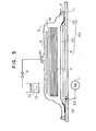
- Fig. 4 is a schematic vertical sectional view of a molding apparatus according to a fourth embodiment of the present invention, and Fig. 4 shows an embodiment wherein two evacuation gates 6d, 6e for reducing the pressure are provided on the reinforcing fiber substrate shown in Fig. 3 , and the resin is injected from both sides of the reinforcing fiber substrate by switching one gate 6d to a resin injection port on the way.
- two evacuation gates 6d, 6e for reducing the pressure are provided on the reinforcing fiber substrate shown in Fig. 3 , and the resin is injected from both sides of the reinforcing fiber substrate by switching one gate 6d to a resin injection port on the way.
- Evacuation gate 6d is switched to the resin injection port on the way of the molding.
- valve 41 is opened, and when it is switched to a resin injection gate, after valve 41 is closed, valve 42 is opened.
- reinforcing fiber substrate 4 is placed on the surface of the mold (tool) processed with grooves 30 via porous sheet 20 and peel ply 3a, and the whole of the materials and members including evacuation gates 6d, 6e disposed in plural on the upper surface side for reducing the pressure and the resin injection gate (grooves 30) disposed on the lower surface side is covered with the bag material.
- valve 41 when valve 41 is opened, valve 42 and valve 9 are closed, while the inside of bag material 8 is evacuated and reduced in pressure by the evacuation through the evacuation gate, valve 9 is opened and the resin is injected into grooves 30 provided as the resin injection gate, matrix resin 10 flows and is impregnated from the lower surface to the upper surface of reinforcing fiber substrate 4.
- the thickness of reinforcing fiber substrate 4 is 10 mm or more, depending on the combination of the resin and the reinforcing fiber substrate, there is a case that it is difficult to impregnate the resin completely up to the upper surface.
- valve 41 can be closed and valve 42 can be opened, thereby switching at least one of the evacuation gates at the upper surface side (evacuation gate 6d in Fig. 4 ) to a resin injection gate.
- the resin is injected also from the upper surface side, and the above-described lack of the resin impregnation can be supplemented.
- the resin is flown from the side of gate 6d to the side of evacuation gate 6e, voids can be pushed out in the direction toward evacuation gate 6e accompanying with this resin flow.
- porous sheet 20 having an appropriate stiffness interrupts the influence of the irregularity of the medium itself and a curing drop of the resin stored in the medium which occurs at the time of curing. Therefore, the surface property of the tool surface side of the molded product taken out after delaminating porous sheet 20/peel plies 3a, 3b/resin distribution medium 5 after releasing from the mold is exhibited as a surface property to which the flatness of the tool surface is almost reflected.
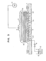
- Fig. 5 is a schematic vertical sectional view of a molding apparatus used for a method of RTM molding according to a fifth embodiment of the present invention, and although the basic portions are the same as those in the aforementioned embodiments, it is different in that a degasification medium 54 comprising gas permeation film 50, gas permeable substrate 51 and seal tape 52 is provided on mold 1, and evacuation can be carried out from the degasification space formed between the gas permeation film 50 and the mold 1 through degasification port 53.
- a degasification medium 54 comprising gas permeation film 50, gas permeable substrate 51 and seal tape 52 is provided on mold 1, and evacuation can be carried out from the degasification space formed between the gas permeation film 50 and the mold 1 through degasification port 53.
- reinforcing fiber material laminate 4 is placed on the surface of mold 1 (tool), the whole of the materials and members including resin injection gate 6f disposed on the upper side and gas permeation film 50 and gas permeable substrate 51 disposed between mold 1 and laminate 4 is covered with bag material 8. In this case, all of the outer edge of gas permeation film 50 is sealed by a dhering it to the mold surface with seal tape 52.
- gas permeation film 50 any material may be used as long as gas can be permeated but a resin and a liquid cannot be permeated, such as a fine porous sheet or resin film, or a substrate formed by coating a fine porous membrane onto a paper or fabric. Further, a film having a flatness on its surface can achieve a good surface quality of a molded product. Furthermore, although it is desirable that gas permeation film 50 has a releasing property, as the case may be, it is possible to integrate it with a molded product.
- Gas permeable substrate 51 preferably has a good gas permeability in order to increase the impregnation property, and preferably has an irregularity as little as possible in order to improve the flatness of a molded product.
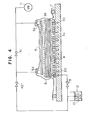
- Fig. 6 shows a sixth embodiment, and this embodiment is an application example of the fifth embodiment shown in Fig. 5 .
- This method is a method for injecting a resin from at least two adjacent resin injection gates among a plurality of resin injection gates 6g, 6h, and the method is effective for a large molded product having a wide area.
- laminate 5 is formed in a flat-plate like shape in Fig. 6 , even in a case of a molded product having a projection or a variation in thickness or a laminate difficult to control a resin flow such as a curved plate, it becomes possible to distribute a resin over the entire material.
- evacuation gate 6a an evacuation route
- evacuation gate 6a can be provided in addition to the above-described evacuation route from the degasification space, and this can be served to the control of impregnation direction at the time of resin injection or the evacuation of excessive resin after resin impregnation.
- Fig. 7 shows an example of a molding apparatus used for a method of RTM molding according to a seventh embodiment of the present invention.
- mold 1 forming a base is made, for example, from a stainless steel or an aluminum alloy, or another metal for mold or an FRP, and formed in, for example, a flat-plate like shape.
- Reinforcing fiber substrate 4 is placed in this mold 1, in the figure, on mold 1.
- Reinforcing fiber substrate 4 is formed, for example, as a laminate of a plurality of reinforcing fiber woven fabrics.
- medium 5 for distributing a resin is placed on reinforcing fiber substrate 4 via peel ply 3.
- Resin distribution medium 5 preferably has a resin flow resistance of 1/10 or less of the resin flow resistance in reinforcing fiber substrate 4, and concretely, a mesh woven fabric made of polyethylene or polypropylene resin and having a mesh size of #400 or less is preferred.
- bag material 8 comprising a gas-tight material.
- bag material 8 in consideration of gas-tight property and thermal resistance, for example, a nylon film is preferably used.
- Sealant 7 made of a synthetic rubber with a high adhesive property prevents the flowing in of air from outside so that a pressure-reduced condition of the inside of bag material 8 can be maintained.
- bag material 8 is formed as a double bag having a first bag material and a second bag material covering the first bag material, an air leakage can be prevented, and as a result, the Vf can be increased.
- Resin injection port 6j and evacuation port 6i for reducing the pressure in bag material 8 by evacuation are provided in the sealed bag material 8, and the respective ports are connected to a resin injection line and an evacuation line.
- resin injection port 6j and evacuation port 6i for example, aluminum C channel materials can be used, and these channel materials may be connected to external members via plastic tubes forming the resin injection line and the evacuation line.
- a thermoplastic resin 10 prepared as a matrix resin for an FRP molded material is stored in a resin pot for example.
- Vacuum trap 13 accumulates an excessive resin evacuated from the molded material through evacuation port 6i.
- Vacuum pump 11 evacuates from the inside covered with bag material 8 through vacuum trap 13 and evacuation port 6i, and maintains a pressure-reduced condition in the inside. Peel ply 3 is interposed for easily removing resin distribution medium 5 from the molded material, and for it, for example, a woven fabric having a releasing function such as a nylon taffeta is used.
- reinforcing fiber substrate 4 is not particularly restricted, for example, glass fibers, carbon fibers, aramide fibers, etc. can be raised. Further, a hybrid structure using or laminating two or more kinds of these fibers may be employed. Further, a sandwich structure interposing a core material such as a foam material or a hollow core between reinforcing fiber layers may be used. As reinforcing fiber substrate 4, it is preferred to use a woven fabric which is preformed at an arbitrary fiber content lower than a target fiber content or a laminate.
- the woven fabric is preferably formed as a two-dimensional or three -dimensional structure
- the laminate may be a laminate in which an arbitrary number of woven fabrics are laminated, and a preform in which woven fabrics are bonded to each other is more preferred from the viewpoint of stabilization of fiber content.
- resin distribution medium 5 for example, a mesh-like material may be used, and a structure may be also employed wherein a resin flow path is formed on mold 1 by grooves and the like and the surface of the mold 1 formed with the resin flow path itself is formed as a resin distribution medium. Further, it is possible to use the reinforcing fiber substrate itself as a resin distribution medium.
- the matrix resin for example, a polyester resin, a vinylester resin, an epoxy resin, a phenol resin, etc. can be raised.
- Fig. 8 shows a molding apparatus used for a method of RTM molding according to an eighth embodiment of the present invention, and shows an apparatus wherein a substantial resin distribution medium is formed on the lower surface side of the reinforcing fiber substrate by processing grooves on the mold instead of disposing a resin distribution medium separately, and the thickness (thickness corresponding to the thickness of the molded material or the reinforcing fiber substrate impregnated with the resin) can be measured by a dial gauge during evacuation of resin. Point different from the apparatus shown in Fig. 7 are as follows.
- Dial gauge 21 measures the thickness of the reinforcing fiber substrate during evacuation of resin.
- Grooves 30 are processed on the mold for distributing the resin instead of a resin distribution medium, and it is preferred that each groove 30 has a width of 0.5 mm to 5 mm and a depth of 1 mm to 6 mm, the arrangement pitch of the grooves is in a range of 2 mm to 25 mm, and the cross-sectional shape of the groove is a reverse trapezoid, a triangle, etc. More preferably, the width is about 1 mm, the depth is about 3 mm, the sectional shape is rectangular, and the pitch is about 8 mm.
- a micrometer or laser measuring device can be raised.
- reinforcing fiber substrate 4 is placed on the molding surface of mold 1, and thereon, peel ply 3 for releasing (for example, a nylon taffeta) and gas permeable material 23 (a polyester nonwoven fabric) are disposed.
- peel ply 3 for releasing for example, a nylon taffeta
- gas permeable material 23 a polyester nonwoven fabric
- reinforcing fiber substrate 4 it is preferred to use a woven fabric which is preformed at an arbitrary fiber content lower than a target fiber volume content or a laminate. Because, when a resin is impregnated, it can be controlled at an arbitrary fiber content, and the impregnation is good and can be stabilized.
- resin injection port 6j and evacuation port 6i are disposed, for example, at the end portion and the central portion ( Fig. 8 ) or at both end portions ( Fig. 7 ), and thereto a resin injection line and an evacuation line are connected, respectively.
- resin injection port 6j are the resin injection line and evacuation port 6i and the evacuation line are provided at least one line, respectively.
- bag material 8 is covered over the whole of the respective members laminated on mold 1 from the upper side, and the portion therearound is sealed by sealant 7 relatively to outside in order to maintain the inside of reinforcing fiber substrate 4, etc. at a pressure-reduced condition.
- valves A1, A2 are closed, valve A3 is opened, and the inside is evacuated by vacuum pump 11 through evacuation port 6i, a vacuum line and vacuum trap 13, and the inside of the cavity (the inside covered with bag material 8) is reduced in pressure at 0.1 MPa or less.
- mold 1 is placed in an oven for heating, and the whole of the mold is heated up to a predetermined temperature.
- valve A1 is opened, and resin 10 is injected into the cavity through resin injection port 6j
- the resin is distributed in gas permeable material 23 toward the evacuation line, and the resin in the gas permeable material 23 is started to be impregnated into reinforcing fiber substrate 4.
- valve A1 is closed and the supply of resin is stopped.
- the fiber volume content Vf at the time of this stopping of resin injection is set in a range of 45% to 60%, more preferably, in a range of 50% to 55%. This is because of suppressing a resin loss due to evacuation as little as possible.
- resin evacuation to resin trap 13 is carried out through evacuation port 6i communicated the vacuum line and resin injection port 6j after valve A2 is opened, until reaching the predetermined fiber volume content.
- the resin evacuation may be continued until the resin becomes gel or the resin is cured, the evacuation is carried out until finally reaching the target fiber volume content of 55% to 65%.
- To set the target fiber volume content in such a range is because, for example, in a case of members for air planes, it is necessary to set the Vf at 55% or more from the comparison in cost and performance with metal materials, and further, if the fiber volume content becomes a high Vf more than 65%, problems are liable to occur such as void generation by bad impregnation, reduction in shear strength between layers in the molded material, etc.
- the target fiber volume content Vf can be set, for example, by the following method.
- a method may be employed wherein a device for measuring the thickness of the laminate (reinforcing fiber substrate) ir disposed beforehand, and when the thickness reaches a thickness corresponding to the target fiber volume content while the thickness of the laminate is measured, valves A2 and A3 are closed.
- the fiber volume content can be defined by the amounts of fibers and resin in the laminate
- a method can be also employed wherein the amount of resin injection and the amount of evacuation corresponding to the predetermined fiber volume content is preset, the resin injection is stopped at the time reaching the target injection amount, and at the stage reaching the target evacuation amount, the resin evacuation is stopped.
- the resin is cured at predetermined temperature and period of time.
- all the submembers including the gas permeable material and members used for the resin injection and evacuation lines together with the bag material and the peel ply are removed, and finally, a molded product is released from the surface of the mold.
- the molded material obtained is served to an aftercuring at predetermined temperature and period of time, as needed.
- Fig. 9 shows an example of a molding apparatus used for a method of RTM molding according to a ninth embodiment of the present invention.
- mold 1 forming a base is made, for example, from a stainless steel or an aluminum alloy, or another metal for mold or an FRP, and formed in, for example, a flat-plate like shape.
- a concave-type cavity is formed in mold 1.
- Reinforcing fiber material laminate 4A is placed in this mold 1, in the figure, on mold 1.
- Reinforcing fiber material laminate 4A is formed as a laminate of a plurality of reinforcing fiber materials 4, and each reinforcing fiber material 4 comprises, for example, a reinforcing fiber woven fabric.
- Symbols 4a, 4b indicate the respective end surfaces of reinforcing fiber material laminate 4A formed in a thick flat plate-like shape.
- resin distribution medium 5 for distributing a resin is disposed via peel ply 3.
- peel ply 3 is disposed so as to cover the whole of reinforcing fiber material laminate 4A.
- This resin distribution medium 5 preferably has a low resin flow resistance of 1/10 or less of the resin flow resistance in reinforcing fiber material laminate 4A, and concretely, a mesh woven fabric made of polyethylene or polypropylene resin and having a mesh size of #400 or less is preferred.
- bag material 8 comprising a gas-tight material.
- bag material 8 in consideration of gas-tight property and thermal resistance, for example, a nylon film is preferably used.
- Sealant 7 made of a synthetic rubber with a high adhesive property prevents the flowing in of air from outside so that a pressure-reduced condition of the inside of bag material 8 can be maintained.
- peel ply 3 is laid in order to easily remove resin distribution medium 5 and the like from a molded material, and as peel ply 3, for example, a woven fabric having a releasing function such as a nylon taffeta can be used.
- Resin injection port 6m and evacuation port 6k for reducing the pressure in bag material 8 by evacuation are provided in the sealed bag material 8, and the respective ports are connected to a resin injection line and an evacuation line.
- resin injection port 6m and evacuation port 6k for example, aluminum C channel materials can be used, and these channel materials may be connected to external members via plastic tubes forming the resin injection line and the evacuation line.
- a thermoplastic resin 10 prepared as a matrix resin for an FRP molded material is stored in a plastic pot for example.
- Vacuum trap 13 accumulates an excessive resin evacuated from the molded material through evacuation port 6k.
- Vacuum pump 11 evacuates from the inside covered with bag material 8 through vacuum trap 13 and evacuation port 6k, and maintains a pressure-reduced condition in the inside.
- Valves A1, B1 are provided for openin/closing the tubes of the resin injection line and the evacuation line, and for these, for example, joints with valves or pinch-off pliers can be used.
- bag material 8 in a double-bag system having a first bag material and a second bag material covering the first bag material, an air leakage can be prevented, and as a result, the volume content of the reinforcing fibers (Vf) can be increased.
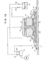
- Fig. 10 shows-a molding apparatus used for a method of RTM molding according to a tenth embodiment of the present invention, and shows an apparatus for molding a molded material with an integral composite formation comprising a stringer material with a composite shape, particularly, with an I-type cross section, and a flat plate-like skin material, as a fiber reinforced resin molded material with a so-called skin/stringer integral structure.
- Point different from the apparatus shown in Fig. 9 are as follows.
- a laminate 4B (reinforcing fiber material laminate) of reinforcing fiber woven fabrics having a flat-plate like cross section forms a part for forming a skin material
- a laminate 4C (reinforcing fiber material laminate) of reinforcing fiber woven fabrics having an I-type cross section forms a part for forming a stringer material.
- Evacuation port 6l for reducing pressure and resin injection port 6n for injecting resin are provided, and C channel materials made of aluminum are preferably used for these ports. The channel materials are connected to external members via plastic tubes.
- Jigs 14 are provided for fixing reinforcing fiber material laminate 4C forming the part for forming the stringer material at a C-type shape from both sides, respectively, and for the jigs 14, for example, metals or foamed cores can be used.
- A5, A4 are valves for opening/closing the tubes, and for these valves, for example, joints with valves or pinch-off pliers can be used.
- the injected resin flows in resin distribution medium 5 disposed over the exposed upper surface portion of part for forming the skin material 4B and the lower end surface portions of the reinforcing fiber material laminate of part for forming the stringer material 4C with an I-type cross section, and the resin is impregnated mainly in the thickness direction relatively to the part for forming the skin material 4B, and impregnated in the direction toward the portions between layers (a direction along the surface of the laminate of the reinforcing fiber materials) from the end surfaces of the reinforcing fiber material laminate relatively to the part for forming the stringer material 4C
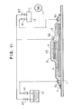
- Fig 11 shows a molding apparatus used for a method of RTM molding according to an eleventh embodiment of the present invention, and shows an apparatus for molding a reinforcing fiber material laminate having a step.
- 4D is a reinforcing fiber material laminate disposed partially on the upper surface of the laminate of reinforcing fiber materials 4 similar to those shown in Fig. 9 .
- the injected resin flows in resin distribution medium 5 disposed so as to extend up to one end surface of reinforcing fiber material laminate 4D, and the resin is permeated in the lamination direction (thickness direction) relatively to the thin plate portion (a portion where the laminate 4D is not laminated), and impregnated in the direction parallel to the lamination direction (namely, the direction toward the portions between layers) from the end surface of the reinforcing fiber material laminate 4D via the resin distribution medium 5 disposed on the surface perpendicular to the lamination direction relatively to the thick plate portion (a portion where the laminate 4D is laminated).
- a plurality of reinforcing fiber materials 4 are laminated on the molding surface of mold 1 to form reinforcing fiber material laminate 4A, and thereon, peel ply 3 for releasing (for example, nylon taffeta) is disposed so as to cover the whole of the laminate 4A.
- peel ply 3 for releasing for example, nylon taffeta
- the outer edge of peel ply 3 is disposed so as to reach up to sealant 7, as shown in Fig. 9 .
- resin distribution medium 5 is disposed near both end portions of reinforcing fiber material laminate 4A so as to extend up to both end surfaces 4a, 4b of the laminate 4A, and further, thereon, resin injection port 6m and evacuation port 6k are disposed, respectively. Then, the whole of these materials is covered with bag material 8 (bag film), and the portion between the edge portion and mold 1 is sealed by sealant 7 over the entire circumference.
- bag material 8 bag film
- valve A1 is closed, and vacuum pump 11 is driven.
- valve B1 is opened, and the inside of the cavity (the inside of bag material b) is evacuated from evacuation port 6k through vacuum trap 13.
- the whole of the members on mold 1 is heated up to a predetermined molding temperature.
- valve A4 is opened, matrix resin 10 is injected through resin injection port 6m by the reduced pressure in bag material 8. After the resin 10 is distributed through one resin distribution medium 5, first, the resin flows quickly in the portions between layers of reinforcing fiber material laminate 4A having a low flow resistance, and the resin reaches the opposite end portion of the laminate 4A.
- the resin is impregnated in the thickness direction of the respective reinforcing fiber materials 4 from the respective portions between layers, namely in the lamination direction of reinforcing fiber materials 4, and at the time when the flow resistance reaches a balanced condition, the resin is impregnated uniformly over the entire area of the reinforcing fiber material laminate 4A.
- the supply of the resin is stopped by closing valve A1. Thereafter, the resin is cured at predetermined temperature and period of time.
- breather 2 glass fiber surface mat, weight: 80 g/m 2
- evacuation gates 6a, 6b were disposed at both end portions, and vacuum pump was connected.
- Peel ply 3a was disposed on breather 2, and thereon, reinforcing fiber substrate 4 comprising carbon fiber woven fabrics (produced by Toray Industries, Inc., plain weave fabric CO6343 using carbon fibers T300, weight: 200 g/m 2 ) laminated by 120 plies was disposed.
- Peel ply 3b was disposed on reinforcing fiber substrate 4, thereon resin distribution medium 5 of a polypropylene mesh material (produced by Tokyo Polymer Corporation, "Netron"TSX-400P) was disposed, and thereon resin injection gate 6c was disposed and it was connected to resin pot 12 via valve 9.
- the whole of these members was covered with bag material 8 (bag sheet), and the circumferential portion was sealed by sealant 7 (where, although omitted in the figure, a double-bag system was employed).
- Valve 9 was closed, the inside of the cavity covered with bag material 8 was evacuated and reduced in pressure by vacuum pump 11, and the whole was heated at 60°C in an oven and the state was maintained for one hour.
- thermoplastic epoxy matrix resin 10 (the resin viscosity at 60°C (injection temperature): 200 mPa ⁇ s, the resin viscosity after expiration of one hour at 60°C : 300 mPa ⁇ s) was stored in resin pot 12 and valve 9 was opened, while the matrix resin 10 was distributed into the medium 5 through the resin injection line, the resin was impregnated in the thickness direction from the upper side toward the lower side, the substrate with a thickness of about 25 mm was completely impregnated with the resin without generating a non-impregnated portion.
- valve 9 was closed to stop the supply of the resin, the whole was heated up to 130°C at about 2 °C/min., and the state was held for 2 hours, the matrix resin was cured. Thereafter, the temperature was lowered down to a room temperature at about 2°C/min., and the whole was taken out from the mold and the bag material 8 was removed. By delaminating the peel ply from the cured material, the cured resin on the surface of the molded product, the medium and the breather were removed. A surface good in surface flatness was obtained for the surface having contacted with the breather, although an irregularity was observed on the surface having contacted with the medium.
- Porous sheet 20 (stainless steel punching metal with a thickness of 0.2 mm, in which holes each having a diameter of 1 mm were processed at a pitch of 10 mm) was disposed on the medium 5a, thereon peel ply 3a was disposed, and thereon, reinforcing fiber substrate 4 comprising carbon fiber woven fabrics (produced by Toray Industries, Inc., plain weave fabric C06343 using carbon fibers T300, weight: 200 g/m 2 ) laminated by 1 20 plies was disposed.
- carbon fiber woven fabrics produced by Toray Industries, Inc., plain weave fabric C06343 using carbon fibers T300, weight: 200 g/m 2
- Peel ply 3b was disposed on reinforcing fiber substrate 4, thereon medium 5b was disposed, and thereon resin injection port 6c was disposed and it was connected to resin pot 12 via valve 9 as a resin injection gate. At that time, a porous sheet may be disposed between peel ply 3b and medium 5b.
- the whole of these members was covered with bag material 8 by a double bag system, and the circumferential portion was sealed by sealant 7.
- Valve 9 was closed, the inside of the cavity covered with bag material 8 was reduced in pressure by vacuum pump 11, and the whole was heated at 60 °C in an oven and the state was maintained for one hour.
- thermoplastic epoxy matrix resin 10 (the resin viscosity at 60°C (injection temperature): 200 mPa ⁇ s, the resin viscosity after expiration of one hour at 60°C : 300 mPa ⁇ s) was stored in resin pot 12 and valve 9 was opened, while the matrix resin 10 was distributed into the upper medium 5b through the resin injection line, the resin was impregnated in the thickness direction of carbon fiber woven fabric laminate 4 from the upper side toward the lower side, the reinforcing fiber material laminate 4 with a thickness of about 25 mm was completely impregnated with the resin without generating a non-impregnated portion.
- valve 9 was closed to stop the supply of the resin, the whole was heated up to 130°C at about 2°C/min., and the state was held for 2 hours, the matrix resin was cured, and thereafter, the temperature was lowered down to a room temperature at about 2°C/min., and the whole was taken out from the mold and the bag material 8 was removed.
- the medium and the porous sheet a surface good in surface flatness was obtained for the surface having contacted with the porous sheet, although an irregularity was observed on the surface having contacted with the medium.
- Porous sheet 20 (stainless steel punching metal with a thickness of 0.2 mm, in which holes each having a diameter of 1 mm were processed at a pitch of 10 mm) was disposed on the molding surface, thereon peel ply 3a was disposed, and thereon, reinforcing fiber substrate 4 comprising carbon fiber woven fabrics (produced by Toray Industries, Inc., plain weave fabric C06343 using carbon fibers T300, weight: 200 g/m 2 ) laminated by 120 plies was disposed.
- carbon fiber woven fabrics produced by Toray Industries, Inc., plain weave fabric C06343 using carbon fibers T300, weight: 200 g/m 2
- Peel ply 3b was disposed on reinforcing fiber substrate 4, thereon medium 5 of a polypropylene mesh material (produced by Tokyo Polymer Corporation, "Netron”TSX-400P) was disposed, and thereon, evacuation gate 6 was placed and it was connected to vacuum pump 11.
- the whole of these members was covered with bag material 8 by a double bag system, and the circumferential portion was sealed by sealant 7.
- Valve 9 was closed, the inside of the cavity covered with bag material 8 was reduced in pressure by vacuum pump 11, and the whole was heated at 60°C in an oven and the state was maintained for one hour.
- thermoplastic epoxy matrix resin 10 (the resin viscosity at 60°C (injection temperature): 200 mPa ⁇ s, the resin viscosity after expiration of one hour at 60°C: 300 mPa ⁇ s) was stored in resin pot 12 and valve 9 was opened, while the matrix resin 10 was distributed into the molding surface with grooves through the resin injection line, the resin was impregnated in the thickness direction of carbon fiber woven fabric laminate 4 from the lower side toward the upper side, the laminate 4 with a thickness of 25 mm was completely impregnated with the resin without generating a non-impregnated portion.
- valve 9 was closed to stop the supply of the resin, the whole was heated up to 130°C at about 2°C/min., and the state was held for 2 hours, the matrix resin was cured, and thereafter, the temperature was lowered down to a room temperature at about 2°C/min., and the whole was taken out from the mold and the bag material 8 was removed.
- Porous sheet 20 (stainless steel punching metal with a thickness of 0.2 mm, in which holes each having a diameter of 1 mm were processed at a pitch of 15 mm) was disposed on the molding surface, thereon peel ply 3a was disposed, and thereon, reinforcing fiber substrate 4 comprising carbon fiber woven fabrics (produced by Toray Industries, Inc., unidirectional woven fabric using carbon fibers T800S, weight: 190 g/m 2 ) laminated by 128 plies was disposed.
- carbon fiber woven fabrics produced by Toray Industries, Inc., unidirectional woven fabric using carbon fibers T800S, weight: 190 g/m 2
- Peel ply 3b was disposed on reinforcing fiber substrate 4, thereon medium 5 of a polypropylene mesh material (produced by Tokyo Polymer Corporation, "Netron”TSX-400P) was disposed, and thereon, evacuation gates 6d, 6e were placed and they were connected to vacuum pump 11.
- the whole of these members was covered with bag material 8 by a double bag system, and the circumferential portion was sealed by sealant 7.
- Valve 9 was closed, the inside of the cavity covered with bag material 8 was reduced in pressure by vacuum pump 11, and the whole was heated at 60°C in an oven and the state was maintained for one hour.
- thermoplastic epoxy matrix resin 10 (the resin viscosity at 60°C (injection temperature): 200 mPa ⁇ s, the resin viscosity after expiration of one hour at 60°C: 300 mPa ⁇ s) was stored in resin pot 12 and valve 9 was opened, while the matrix resin 10 was distributed into the molding surface with grooves through the resin injection line, the resin was impregnated in the thickness direction of carbon fiber woven fabric laminate 4 from the lower side toward the upper side. However, in a case where the state is held, at the time when the impregnation progresses up to a position of about 2/3 of the thickness of reinforcing fiber substrate 4, the resin impregnation becomes astringent.
- valve 41 when the resin was impregnated up to a position of 1/2 of the thickness of reinforcing fiber substrate 4, valve 41 was stopped, valve 42 was opened, and evacuation gate 6d was switched to a resin injection gate.
- the resin injected from gate 6d was distributed in distribution medium 5 in a direction toward evacuation gate 6e, and the resin was impregnated into the substrate in the downward direction via the inside of the medium 5. Finally, the resin was impregnated over the entire area of the inside of the substrate. Then, valve 9, 42 were closed to stop the supply of the resin.
- the whole was heated up to 130°C at about 2°C/min., and the state was held for 2 hours, the matrix resin was cured, and thereafter, the temperature was lowered down to a room temperature at about 2°C/min., and the whole was taken out from the mold and the bag material 8 was removed.
- reinforcing fiber substrate 4 (thickness: about 25 mm) comprising carbon fiber woven fabrics (produced by Toray Industries, Inc., plain weave fabric CO6343 using carbon fibers T300, weight: 200 g/m 2 ) laminated by 120 plies was disposed on gas permeation film 50.
- peel ply 3b was disposed on reinforcing fiber substrate 4, thereon resin distribution medium 5 of a polypropylene mesh material (produced by Tokyo Polymer Corporation, "Netron”TSX-400P) was disposed, and thereon, resin injection gate 6f was placed and it was connected to resin pot 12 via valve 9.
- the whole of these members was covered with bag material 8, and the circumferential portion was sealed by sealant 7.
- Valve 9 was closed, the inside of the cavity covered with bag material 8 was evacuated and reduced in pressure by vacuum pump 11, and the whole was heated at 70°C in an oven and the state was maintained for one hour.
- thermoplastic epoxy matrix resin 10 (the resin viscosity at 70°C (injection temperature): 130 mPa ⁇ s, the resin viscosity after expiration of one hour at 70°C : 320 mPa ⁇ s) was stored in the resin pot and valve 9 was opened, while the matrix resin 10 was distributed into the medium 5 through the resin injection line, the resin was impregnated in the thickness direction of reinforcing fiber substrate 4 from the upper side toward the lower side.
- gas permeation film 50 does not exist, the gas present near the lower surface of the substrate is not well exhausted, the surface of the molded material obtained becomes "pockmarked-like", but, in this example, by providing gas permeation film 50, a degasification space was formed between the film and mold 1, the above-described gas was completely degasified from the entire area of the lower surface of reinforcing fiber substrate 4 through gas permeable substrate 51, and therefore, in spite of the thickness of the substrate of 25 mm, the resin was completely impregnated without any non-impregnated portion, and in particular, the surface quality was remarkably improved.
- valve 9 was closed to stop the supply of the resin, the whole was heated up to 130°C at about 2°C/min., and the state was held for 2 hours, the matrix resin was cured. Thereafter, the temperature was lowered down to a room temperature at about 2°C/min., and the whole was taken out from the mold and the bag material 8 was removed. The lower surface of the cured molded product was obtained as a surface having a good surface flatness by delaminating gas permeation film 50.
- reinforcing fiber substrate 4 (thickness: about 25 mm) comprising carbon fiber woven fabrics (produced by Toray Industries, Inc., plain weave fabric C06343 using carbon fibers T300, weight: 200 g/m 2 ) laminated by 120 plies was disposed on gas permeation film 50.
- evacuation gate 6a was disposed also on one side of the lower surface of the reinforcing fiber substrate.
- Peel ply 3b was disposed on reinforcing fiber substrate 4, thereon resin distribution medium 5 of a polypropylene mesh material (produced by Tokyo Polymer Corporation, "Netron"TSX-400P) was disposed, and thereon, two resin injection gates 6g, 6h were placed and they were connected to resin pot 12 via valve 9. The whole of these members was covered with bag material 8, and the circumferential portion was sealed by sealant 7. Valve 9 was closed, the inside of the cavity covered with bag material 8 was evacuated and reduced in pressure by vacuum pump 11, and the whole was heated at 70°C in an oven and the state was maintained for one hour.
- resin distribution medium 5 of a polypropylene mesh material (produced by Tokyo Polymer Corporation, "Netron"TSX-400P) was disposed, and thereon, two resin injection gates 6g, 6h were placed and they were connected to resin pot 12 via valve 9.
- the whole of these members was covered with bag material 8, and the circumferential portion was sealed by sealant 7.
- Valve 9 was closed, the inside of the cavity
- thermoplastic epoxy matrix resin 10 (the resin viscosity at 70 °C (injection temperature): 130 mPa ⁇ s, the resin viscosity after expiration of one hour at 70°C: 320 mPa ⁇ s) was stored in the resin pot and valve 9 was opened, while the matrix resin 10 flowed in medium 5 simultaneously through two resin injection lines and the resin was distributed on the surface, the resin was impregnated in the thickness direction of reinforcing fiber substrate 4 from the upper side toward the lower side, and the substrate with a thickness of about 25 mm was impregnated completely without any non-impregnated portion.
- valve 9 was closed to stop the supply of the resin, the whole was heated up to 130°C at about 2°C/min., and the state was held for 2 hours, the matrix resin was cured.
- the time for resin impregnation was short by the evacuation also through evacuation gate 6a, as compared with that in Example 5.
- the temperature was lowered down to a room temperature at about 2 °C/min., and the whole was taken out from the mold and the bag material 8 was removed.
- the lower surface of the cured molded product was obtained as a surface having a good surface flatness by delaminating gas permeation film 50.
- a carbon fiber woven fabric cut at a length of 500 mm and a width of 500 mm was laid up on mold 1 comprising a stainless steel flat plate.
- a reinforcing fiber material used for forming a reinforcing fiber substrate was a unidirectional woven fabric CZ8431DP (weight: 190 g/m 2 ) of "TORAYCA" T800S produced by Toray Industries, Inc., and it was laminated by 128 plies totally.
- valves A1, A2 were closed, valve A3 was opened, and the evacuation was carried out through the evacuation port via the vacuum line and vacuum trap 13 to reduce the pressure in the cavity down to 0.1 MPa or less.
- the mold was placed in an electric oven and the inside of the oven was heated at 60°C.
- valve A1 was opened and matrix resin 10 was injected through resin injection port 6j at a vacuum pressure.
- an epoxy resin (the resin viscosity at 60°C (injection temperature): 200 mPa ⁇ s, the resin viscosity after expiration of one hour at 60°C: 300 mPa ⁇ s) was used.
- the injected resin was impregnated into the substrate 4 while flowing in resin distribution medium 5 having a low flow resistance.
- valve A1 was closed to stop the supply of the resin.
- the fiber volume content of the substrate capable of being estimated from the thickness of the reinforcing fiber substrate was about 48 %.
- valve A2 was opened, the resin injection line was opened to the vacuum side via the vacuum trap, and excessive resin in the reinforcing fiber substrate was evacuated into the vacuum trap 13 from the end portion of the reinforcing fiber substrate. Thereafter, at the time when the evacuation amount of the resin reached a predetermined amount of 1150 cm 3 , valves A2, A3 were closed to stop the supply of the resin. Then, the temperature in the electric oven was elevated up to 130°C, and heated and cured for about two hours. After the heat-curing, the sub members such as the bag material were removed, CFRP (carbon fiber reinforced plastic) molded material was released from the molding surface.
- CFRP carbon fiber reinforced plastic
- the fiber volume content of the CFRP molded material As the result of determination of the fiber volume content of the CFRP molded material at positions of the resin injection side, the evacuation side and an intermediate point therebetween, they were in a range of 57.2 % to 58.2 %. Namely, as compared with the time before resin evacuation immediately after resin impregnation, the fiber volume content could be increased up to a value within the range of the target value.
- a carbon fiber woven fabric 4 cut at a length of 500 mm and a width of 500 mm was laid up on mold 1 comprising a stainless steel flat plate, on which #-type grooves 30 (width: 1 mm, depth: 4 mm, pitch: 15 mm) were processed as a flow path of resin.
- the used carbon fiber woven fabric 4 was a unidirectional woven fabric CZ8431DP (weight: 190 g/m 2 ) of "TORAYCA" T800S produced by Toray Industries, Inc., and it was laminated by 128 plies totally.
- gas permeable material 23 (polyester non-woven fabric) was disposed via peel ply 3, and thereon, evacuation port 6i was disposed.
- resin injection port 6j was disposed on the grooves 30 for resin flow path formed on mold 1, the whole of these members was covered with bag material 8 (nylon film) by a double bag system and the circumferential portion was sealed by sealant 7 made of a synthetic rubber having a high adhesive property.
- valves A1, A2 were closed, valve A3 was opened, and the evacuation was carried out through evacuation port 6i via the vacuum line and vacuum trap 13 to reduce the pressure in the cavity down to 0.1 MPa or less.
- the mold was placed in an electric oven and the inside of the oven was heated at 60°C.
- valve A1 was opened and matrix resin 10 was injected through resin injection port 6j at a vacuum pressure.
- the resin the epoxy resin of Example 1 was used.
- the injected resin was distributed in the grooves for distributing resin, and the resin in the grooves was impregnated into the substrate.
- the fiber volume content was 48 %.
- valve A1 was closed and valve A2 was opened, and excessive resin in the reinforcing fiber substrate was evacuated into vacuum trap 13.
- the target fiber volume content of the CFRP molded material was set at 55 to 60 %. Since it was recognized from the experimental result beforehand that the curing shrinkage of the molded material in the thickness direction was about 1.2 %, at the time when the thickness became 23.8 mm, valves A2, A3 were closed to stop the evacuation of the resin. Thereafter, the temperature in the oven was elevated up to 130°C, and heated and cured for about two hours.
- the present invention was applied to the molding of a thick flat plate.
- a carbon fiber woven fabric 4 (reinforcing fiber material) cut at a length of 300 mm and a width of 300 mm was laid up on mold 1, comprising a stainless steel flat plate, by 128 plies, to form reinforcing fiber material laminate 4A having a total thickness of about 25 mm.
- the used reinforcing fiber material was a unidirectional woven fabric CZ8431DP (weight: 190 g/m 2 ) of "TORAYCA" T800S produced by Toray Industries, Inc.
- peel ply 3 nylon taffeta
- resin distribution medium 5 polypropylene mesh material
- resin injection port 6m and evacuation port 6k were disposed so as to communicate with both ends of the laminate 4A
- bag material 8 nylon film
- sealant 7 made of a synthetic rubber having a high adhesive property
- valve A1 was closed, valve B1 was opened, and evacuation port 6k was communicated with the vacuum line via vacuum trap 13 communicated with the evacuation line, and the pressure in the cavity was reduced down to 0.1 MPa or less.
- valve A1 was opened and matrix resin 10 was injected through resin injection port 6m under a pressure-reduced atmosphere with 0.08 to 0.1 MPa.
- an epoxy resin the resin viscosity at 60°C (injection temperature): 200 mPa ⁇ s, the resin viscosity after expiration of one hour at 60°C : 300 mPa ⁇ s
- an epoxy resin the resin viscosity at 60°C (injection temperature): 200 mPa ⁇ s, the resin viscosity after expiration of one hour at 60°C : 300 mPa ⁇ s
- the injected resin first flowed in resin distribution medium 5 having a low flow resistance, and at the time reaching the end of reinforcing fiber material laminate 4A, the resin flowed therefrom mainly in the laminate 4A in the direction along the lamination surface of the laminate 4A, and thereafter, the resin was impregnated in the thickness direction, and this resin flow was observed from the above position of transparent bag material 8.
- valve A1 was closed to stop the supply of the resin. Thereafter, the temperature in the oven was elevated up to 130°C, and heated and cured for about two hours. After the heat-curing, the sub members such as the bag material 8 were removed, and the CFRP molded material was taken out from the molding surface. As a result, the CFRP molded material was completely impregnated with resin in spite of a relatively small thickness of 25 mm. Further, the surface property of the molded material was flat.
- the present invention was applied to the molding of a skin/stringer integrally structural material.
- a carbon fiber woven fabric 4 (reinforcing fiber material) cut at a length of 500 mm and a width of 500 mm was laid up on mold 1 to form reinforcing fiber material laminate 4B.
- the used reinforcing fiber material was a unidirectional woven fabric (weight: 190 g/m 2 ) of "TORAYCA” T800S produced by Toray Industries, Inc., and it was laminated by 128 plies totally (hereinafter, referred to as "reinforcing fiber material laminate for forming a skin material 4B").
- a carbon fiber woven fabric 4 cut at a width of 98 mm and a length of 500 mm was placed by 32 plies using jig 14 for fixing a C-type shape.
- Another laminate of the carbon fiber woven fabric 4 was further prepared, and the two laminates were disposed so as to form a structure back to back symmetrically with jigs 14 disposed at both sides to form a reinforcing fiber material laminate having an I-type cross section, and it was placed on the reinforcing fiber material laminate for forming a skin material 4B which had been already 1 aid up.
- reinforcing fiber material laminate placed on the reinforcing fiber material laminate for forming a skin material 4B is referred to as "reinforcing fiber material laminate for forming a stringer material 4C").
- peel ply 3 nylon taffeta
- resin distribution medium 5 polypropylene mesh material
- resin injection ports 6m, 6n and evacuation ports 6k, 6l were disposed on these reinforcing fiber material laminates, as shown in Fig. 10 .
- bag material 8 nylon film
- sealant 7 made of a synthetic rubber having a high adhesive property.
- valves A4, A5 were closed, valves B1, B2 were opened, and evacuation ports 6k, 6l were opened via vacuum trap 13 communicated with the vacuum line, and the pressure in the cavity was reduced down to 0.1 MPa or less.
- the mold was placed in an electric oven and the inside of the oven was heated at 70°C.
- valves A4, A5 were opened and matrix resin 10 was injected through resin injection ports 6m, 6n under a pressure-reduced condition.
- an epoxy resin the resin viscosity at 70C (injection temperature): 130 mPa ⁇ s, the resin viscosity after expiration of one hour at 60°C: 320 mPa ⁇ s
- the injected resin flowed in the resin distribution medium having a low flow resistance, and was impregnated into the substrate.
- the resin was impregnated in the thickness direction relatively to the reinforcing fiber material laminate for forming a skin material 4B, relatively to the reinforcing fiber material laminate for forming a stringer material 4C, the resin flowed in the direction of portions between layers of the laminate from the end surface of the lower side of the I-type reinforcing fiber material laminate, and was impregnated mainly in the thickness direction of the respective reinforcing fiber materials (namely, the thickness direction of the I-type reinforcing fiber material laminate) after being permeated into the I-type reinforcing fiber material laminate.
- valves A4, A5 were closed to stop the supply of the resin.
- the temperature in the oven was elevated up to 130°C, and heated and cured for about two hours.
- the sub members such as the bag material 8 were removed, and the CFRP molded material was taken out from the molding surface.
- the CFRP molded material obtained the resin was completely impregnated particularly up to the corners of the stringer part. Further, the surface property of the stringer part was flat.
- the present invention was applied to the molding of a panel with a step.
- a carbon fiber woven fabric 4 (produced by Toray Industries, Inc., plain weave fabric C06343 using carbon fibers T300, weight: 190 g/m 2 ) cut at a length of 500 mm and a width of 500 mm was laid up by 24 plies on mold 1 of an aluminum flat plate, and thereon, the carbon fiber woven fabric cut at a length of 150 mm and a width of 500 mm was laid up by 56 plies was laid up as a thick plate portion, to form reinforcing fiber material laminate 4D.
- Fig. 11 a carbon fiber woven fabric 4 (produced by Toray Industries, Inc., plain weave fabric C06343 using carbon fibers T300, weight: 190 g/m 2 ) cut at a length of 500 mm and a width of 500 mm was laid up by 24 plies on mold 1 of an aluminum flat plate, and thereon, the carbon fiber woven fabric cut at a length of 150 mm and
- valves A1, A2 were closed to stop the resin injection, the electric oven was heated up to 130°C, and the resin was cured for about two hours at a condition keeping the temperature.
- the sub members such as the bag material 8 were removed, and the CFRP molded material was taken out from the molding surface.
- the resin was completely impregnated particularly as to all portions of the thin plate portion and the thick plate portion, and the surface property of the stringer part was flat.
- the method of RTM molding according to the present invention is suitable particularly for molding of a thick FRP structural material, and according to the present invention, an FRP structural material, having an excellent designability, or having excellent lightweight property and strength by increase of fiber volume content, can be molded.
Abstract
Description
- The present invention relates to improvement of a method of Resin Transfer Molding (hereinafter, referred to as "RTM") for molding a structural material of a fiber reinforced plastic (hereinafter, referred to as "FRP"), and specifically, to a method of RTM molding in which it is possible to mold a thick material, and further, it is possible to improve a quality of surface property or to increase a fiber volume content (hereinafter, also referred to as "Vf") of an FRP molded material to be molded. Although the title of the present invention is referred to as "method of RTM molding" in this specification, the technical concept according to the present invention includes this molding method due to RTM itself and a method for producing an FRP molded material using the molding method.
- Although FRP has been used in various fields, as a method for producing an FRP structural material, general is a so-called prepreg/autoclave molding method wherein, after a preform having a shape of a structural material to be molded is formed beforehand by prepregs, the preform is cured in an autoclave set at a predetermined condition in temperature and pressure. However, recently a method of RTM molding is paid attention to in order to reduce the production cost, and this method is developed gradually. Many methods are proposed as RTM molding methods for producing panels and beam materials which are structural members for air planes or architecture requiring high strength, lightweight and low cost or for producing FRP molded products such as outer panels of vehicles. For example, there are a method of RTM molding for molding a large FRP structural material (for example,
JP-A 12-145042 U.S. Patent 5,052,906 ). - In the method of RTM molding disclosed in
JP-A 12-145042 - As the problem in the above-described molding method, although resin distribution media are disposed on both surfaces of the reinforcing fiber substrate, because the resin impregnation is carried out basically from one surface side relatively to the reinforcing fiber substrate, there is a limit in a distance capable of being impregnated in the thickness direction of the substrate. Therefore, if the reinforcing fiber substrate is too thick, a predetermined impregnation becomes impossible.
- Where, it is known that the permeability of resin into the reinforcing fiber substrate can be determined generally by the following equation.

I: permeability, ε: resistance of substrate, α: constant,
P: vacuum pressure in substrate, µ(t): viscosity,
t: expiration time - Here, the permeability corresponds to a distance (thickness) of resin impregnation into the substrate.
- With respect to resin impregnation into a reinforcing fiber substrate, although the constant and the viscosity in the above-described equation are different depending on the kinds of the substrate and the resin, because the impregnation distance is astringent accompanying with expiration of time, and further, there occurs an increase of the viscosity and the resin gradually becomes gel, a limit is generated in the distance at which the resin can impregnate, and if the thickness of the reinforcing fiber substrate is a certain thickness or more, it becomes impossible to impregnate the resin any longer in the above-described conventional method.
- In order to impregnate the resin into a thick reinforcing fiber substrate, it is considered to impregnate the resin into the reinforcing fiber substrate from both the resin distribution media on both surfaces of the reinforcing fiber substrate. In the above-described molding method, however, because the resin distribution media having substantially same shape and property are disposed on both surfaces, when merely the resin is impregnated from the both surface sides, the resin is impregnated in the thickness direction of the substrate simultaneously and in a same manner, voids are hard to be pushed out in the side directions, and the voids are likely to be enclosed in the substrate. If the voids are enclosed, it is difficult to obtain a target property of a molded product. In order to avoid such an enclosure of voids, the resin impregnation is carried out basically from one surface side.
- Further, as another problem on the above-described molding method, there is a problem that it is difficult to obtain a good flatness on the design surface of the molded product. Namely, the above-described resin distribution medium is formed as a member having a relatively large surface irregularity with a low resistance for gas permeation in order to increase the resin distribution property. However, if the resin distribution media having such a relatively large surface irregularity are disposed on both surfaces of the reinforcing fiber substrate and the molding is carried out in this condition, the relatively large surface irregularity of the resin distribution medium is reflected to the design surface which is one surface of the molded product. As a result, the designability is damaged and an irregularity is formed on the surface of the molded product, and therefore, there is a problem that the properties such as aerodynamic property decrease.
- In order to solve such problems, it is considered to use a resin distribution medium having a small surface irregularity, but if done so, the resistance for gas permeation becomes too great, and a target resin distribution property cannot be obtained. Further, because the gas permeation from the reinforcing fiber substrate at the time of evacuation also deteriorates, the vacuum degree does not increase, and it becomes difficult to completely impregnate the resin in the thickness direction particularly for a thick substrate.
- Thus, although the degree of the irregularity of the resin distribution medium affects the resin distribution and gas permeation performances, the irregularity of the resin distribution medium for improving resin distribution and gas permeation performances (a relatively large irregularity) and the irregularity of the resin distribution medium for improving the surface property of the molded product (a relatively small irregularity) are in a relationship opposite to each other. Therefore, in the conventional method wherein substantially same resin distribution media are disposed on both surfaces of a reinforcing fiber substrate, it is difficult to achieve both of increase of the resin impregnation property and improvement of the surface property of a molded product, and it becomes particularly difficult in the molding using a thick reinforcing fiber substrate.
- In order to improve the quality on the surface property of a molded product, a condition is frequently employed wherein a gas permeable material is not disposed on a tool surface side. In such a case, however, because the gas permeation in the substrate deteriorates and the vacuum degree does not increase, reduction in impregnation may occur.
- In the method of RTM molding disclosed in
U.S. Patent 5,052,906 , a reinforcing fiber substrate is placed on a mold and a resin distribution medium is disposed at a position opposite to the mold, a resin injection port and an evacuation port are disposed, they are covered with a bag material from the upper side, and a matrix resin is injected at a condition where the inside of a cavity is reduced in pressure by evacuation. The flowing-in route of the resin into the substrate is formed as a route in which the resin is distributed mainly from the injection port along the surface direction of the substrate disposed in the mold and the distributed resin is impregnated in the thickness direction of the substrate. - In the above-described method, when the resin injection is carried out at a so-called high Vf condition where the fiber volume content (Vf) of the reinforcing fiber substrate is 55% or more, namely, at a condition where a gap between reinforcing fibers is small, although the fiber volume content of a final molded product itself becomes high, the impregnation property of the resin into the molded product is poor. Therefore, in a case of a thick molded product having a plate thickness of, for example, 25 mm or more, the resin does not reach corners of the molded product, and only a product having a defect due to a resin non-impregnated portion is produced as a structural material.
- On the other hand, in a case where the Vf of the reinforcing fibers is, for example, 45% and the gap between reinforcing fibers is relatively great, because the fiber volume content of the final molded product becomes low although a good resin impregnation property can be obtained, only a product having poor strength and lightweight property can be obtained. Namely, the resin impregnation property and the fiber volume content Vf are in a relationship opposite to each other, and it is difficult to achieve both improvement of the resin impregnation property and increase of the fiber volume content together. Moreover, although it is preferred depending on a molded product to control the fiber volume content from the necessity of stabilization of the quality, it is also difficult to satisfy such a requirement.
- Further, although usually the reinforcing fiber substrate is formed as a laminate of a plurality of reinforcing fiber materials in order to obtain an FRP molded product with a predetermined thickness, as to the thickness direction, that is, as to the direction perpendicular to the lamination surface in the reinforcing fiber material laminate, the resistance against the resin flow is generally high, and there is a limit in the reaching distance of the resin being impregnated in the thickness direction of the substrate. Therefore, in a case where it is required to increase the number of lamination of the reinforcing fiber materials such as a case of planning to mold a high-strength product, it may be difficult to completely impregnate the resin into the corners of the reinforcing fiber material laminate, and consequently, an FRP structural material having a certain thickness or more substantially cannot be molded.
- Accordingly, an object of the present invention is to provide a method of RTM molding (method for producing an FRP) which can solve the above-described various problems in the conventional methods, which can mold even a thick FRP structural material with a good resin impregnation property, and which can realize improvement of the surface quality, increase of the lightweight property and achievement of an excellent strength.
- To accomplish the above object, a method of RTM molding according to the present invention wherein a reinforcing fiber substrate is placed in a mold, resin distribution media each exhibiting a resin flow resistance lower than a resin flow resistance of the reinforcing fiber substrate are placed on both surfaces of the reinforcing fiber substrate, and after a pressure in the mold is reduced by evacuation, a resin is injected into the mold through the resin distribution media to impregnate the reinforcing fiber substrate with the resin injected, is characterized in that a resin flow resistance of a first resin distribution medium placed on a first surface of the reinforcing fiber substrate is set lower than a resin flow resistance of a second resin distribution medium placed on a second surface of the reinforcing fiber substrate, and the evacuation is carried out through the second resin distribution medium while the resin is injected into the first resin distribution medium to impregnate the reinforcing fiber substrate with the resin injected (a first method).
- Namely, in the method of RTM molding according to the present invention, an intentional large/small relationship is given to the resin flow resistances of the resin distribution media placed on both surfaces of the reinforcing fiber substrate. In practice, the resin flow resistance can be determined by measuring a gas permeation resistance and determining it as a value corresponding to the measured gas permeation resistance. Alternatively, because the permeability generally shown bu the following equation has the same meaning as that of the resin flow resistance, such a value may be employed.

L: impregnation distance (m)
K: permeability (m2)
β : constant
P: vacuum pressure in substrate (kg/m2)
µ(t): viscosity (kg · s/m2)
t: expiration time - In the present invention, although the reinforcing fiber substrate may be a single layer or may be formed as a laminate of a plurality of reinforcing fiber materials, because the method of RTM molding according to the present invention is suitable particularly for molding of a thick product, namely, for molding for impregnating a resin into a thick reinforcing fiber substrate, the target of the present invention is mainly a case where a reinforcing fiber substrate comprising a laminate of a plurality of reinforcing fiber materials is used.
- In this method of RTM molding according to the present invention, it is preferred that the resin flow resistance of the above-described second resin distribution medium is set lower than the resin flow resistance of the above-described reinforcing fiber substrate. By this, because the resin flow resistance (gas permeation resistance) of the second resin distribution medium is suppressed sufficiently low as compared with the resin flow resistance (gas permeation resistance) of the reinforcing fiber substrate although the resin flow resistance (gas permeation resistance) of the second resin distribution medium is higher than the resin flow resistance (gas permeation resistance) of the first resin distribution medium, the reduction of the vacuum degree in the substrate due to deterioration of gas permeation from the reinforcing fiber substrate is suppressed, and damage to the resin impregnation into a thick reinforcing fiber substrate can be avoided.
- Further, it is preferred that the resin flow resistance of the above-described first resin distribution medium is set at 1/3 of the resin flow resistance of the reinforcing fiber substrate or less, because the resin can be distributed into the medium quickly. Further, more preferably, it is set at 1/10 or less to distribute the resin more quickly. By this, the distribution property of the resin injected into the first resin distribution medium in the surface direction of the reinforcing fiber substrate is ensured to be sufficiently high, the resin injected into the first resin distribution medium is quickly impregnated in the thickness direction of the reinforcing fiber substrate while the resin is distributed quickly in a direction along the surface. Under such a condition where the resin flow resistance of the first resin distribution medium and the resin flow resistance of the second resin distribution medium are satisfied, the large/small relationship is given to the resin flow resistance of the first resin distribution medium and the resin flow resistance of the second resin distribution medium.
- Further, in the method of RTM molding according to the present invention, it is preferred that a peel ply capable of being removed together with a resin distribution medium after molding is interposed between at least one resin distribution medium and the reinforcing fiber substrate. By this, the resin distribution medium can be easily delaminated. However, after releasing the molded product from the mold, at least one resin distribution medium may be left in the molded product without delaminating it from the molded product. In this case, the peel ply is not necessary for the side where the resin distribution medium is left.
- Further, in the method of RTM molding according to the present invention, a method may be employed wherein a porous sheet is interposed between at least one resin distribution medium and the reinforcing fiber substrate. This porous sheet has a function different from that of the above-described peel ply, and it is a sheet for suppressing a transfer of the irregularity of the resin distribution medium to the reinforcing fiber substrate side while maintaining the resin distribution function of the resin distribution medium. Therefore, the sheet is preferably disposed on the design surface side of the molded product.
- Further, in the method of RTM molding according to the present invention, at least one resin distribution medium may be formed by providing a groove as a resin flow path on an inner surface of the mold. In this case, even if a separate resin distribution medium is not made, it is possible to use the inner surface of the mold itself as a resin distribution medium.
- Further, in the method of RTM molding according to the present invention, it is preferred that injection of a resin is started also through the second resin distribution medium before the above-described resin reaches the above-described second surface. Namely, from this time, the resin impregnation from both surfaces is substantially started.
- Further, in the method of RTM molding according to the present invention, a method can be employed wherein, in a case where at least two resin injection gates are disposed above the first resin distribution medium, the resin injection is carried out simultaneously from at least two resin injection gates adjacent to each other, or from all resin injection gates. Since the evacuation through the second resin distribution medium as well as the resin injection are carried out simultaneously while the quick resin impregnation is achieved, the generation of resin non-impregnation portions can be prevented.
- Further, the present invention the following method of RTM molding from the viewpoint of molding particularly an excellent design surface. Namely, a method of RTM molding according to the present invention is characterized in that a reinforcing fiber substrate is placed in a mold, a resin distribution medium exhibiting a resin flow resistance lower than a resin flow resistance of the reinforcing fiber substrate is placed on a surface of the reinforcing fiber substrate opposite to the mold, a degasification medium comprising a gas permeation film and a gas permeable substrate is provided between the reinforcing fiber substrate and the mold, a resin is injected into the mold through the resin distribution medium after a pressure in the mold is reduced by evacuation, and the resin injected is impregnated into the reinforcing fiber substrate by evacuating the resin injected from a degasification space formed between the gas permeation film and the mold (a second method).
- In this second method, the above-described reinforcing fiber substrate comprises, for example, a laminate of reinforcing fiber materials.
- Further, in the above-described second method, it is preferred that the above-described gas permeation film has a releasability capable of being delaminated from a molded product after molding.
- Further, in the above-described second method, particularly in a case where a product with a wide area is molded, it is preferred that at least two resin injection gates are disposed above the resin distribution medium, and resin injection is carried out simultaneously from at least two resin injection gates adjacent to each other, or from all resin injection gates.
- Furthermore, in the above-described second method, particularly in a case where a product with a wide area is molded, it is also preferred that at least one evacuation route is provided in the mold in addition to an evacuation route from the degasific ation space formed between the gas permeation film and the mold.
- In the above-described method of RTM molding according to the present invention (the first method), the resin is injected into the first resin distribution medium having a lower resin flow resistance, and the injected resin is quickly impregnated into the reinforcing fiber substrate in the thickness direction while the resin is distributed quickly and broadly in a direction along the first surface of the reinforcing fiber substrate. Then, basically the inside of the mold is reduced in pressure by evacuation via the second resin distribution medium having a higher resin flow resistance, and the above-described injected resin is impregnated into the reinforcing fiber substrate having an evacuated and pressure-reduced condition. At that time, since the resin flow resistance (gas permeation resistance) of the second resin distribution medium is suppressed sufficiently low as compared with the resin flow resistance (gas permeation resistance) of the reinforcing fiber substrate although it is higher than the resin flow resistance (gas permeation resistance) of the first resin distribution medium, it is suppressed to reduce the vacuum degree in the substrate by deterioration of gas permeation from the reinforcing fiber substrate, and a quick resin impregnation can be ensured. Therefore, even for a thick reinforcing fiber substrate, a sufficiently good resin impregnation can be ensured. Since the resin flow resistance (gas permeation resistance) of the second resin distribution medium is set higher than that of the first resin distribution medium, the second resin distribution medium can be formed as a medium with a small irregularity as compared with the first resin distribution medium, and even if a transfer of the surface form of this second resin distribution medium to the surface of a molded product occurs, the degree of the irregularity on the surface of the molded product ascribed to the transfer can be suppressed small. Therefore, by setting this surface side to be a design surface side, a desirable design surface of the molded product having a small irregularity can be obtained.
- In a molding requiring resin impregnation into a further thick reinforcing fiber substrate, in particular, in a case where it is difficult to impregnate the resin sufficiently up to the surface at the second resin distribution medium side of the reinforcing fiber substrate only by the above-described resin impregnation from the first resin distribution medium side into the reinforcing fiber substrate (in a case exceeding the conventional resin impregnation limit), before the resin impregnated from the first resin distribution medium side into the reinforcing fiber substrate reaches the second surface of the reinforcing fiber substrate, the resin injection through the second resin distribution medium can be started. By this resin injection from the second resin distribution medium side, the resin impregnation can be supplemented for a portion in which the resin is hardly impregnated into the reinforcing fiber substrate sufficiently, that is, for a portion of the second surface side, and it becomes possible to impregnate the resin sufficiently over the entire region of the reinforcing fiber substrate in the thickness direction. Namely, in this process, the resin impregnation in the thickness direction of the reinforcing fiber substrate is carried out mainly by the impregnation from the first resin distribution medium side, and a lack of the impregnation is supplemented by the impregnation from the second resin distribution medium side. Further, because a latge/small relationship is given between the gas permeation resistances (resin flow resistances) of the first and second resin distribution media, while a quick resin impregnation is carried out from the first resin distribution medium side, in the second resin distribution medium side, the resin impregnation is supplemented, and voids pushed out from the first resin distribution medium side by the impregnated resin are pushed out at a relatively slow speed toward side portions, that is, in a direction along the second surface of the reinforcing fiber substrate, without being enclosed in the reinforcing fiber substrate by the resin impregnated from the second resin distribution medium side. As a result, in spite of resin impregnation from both surface sides, it can be avoided to enclose voids in the reinforcing fiber substrate, and besides, the resin impregnation at the second surface side is supplemented, and therefore, it becomes possible to well mold a thick material without accompanying with the problem of void enclosure. Moreover, in this case, by setting the second resin distribution medium side to be a design surface as described above, an excellent design surface with small irregularity can be obtained at the same time. Namely, molding of a thick material and improvement of the surface quality can be both achieved.
- Further, the aforementioned method of RTM molding according to the present invention (the second method) is effective for the following cases namely, in a case where a flatness of a molded surface (a design surface) at the mold side is required further strongly, and in a molding where a resin impregnation into a thick and broad-area reinforcing fiber substrate is required, in particular, a degasification medium comprising a gas permeation film and a gas permeable substrate can be provided between the reinforcing fiber substrate and the surface of the mold as means for always effectively operating the degasification route from any portion of the mold surface. By this, at the time of resin injection, even if there is a difference in time for reaching of resin to the lower surface side (design surface forming side) of the reinforcing fiber substrate and a portion late in impregnation is liable to occur, by evacuation from the degasification formed between the gas permeation film and the mold, finally it becomes possible to completely impregnate the resin over the entire surface. Consequently, a design surface along the mold surface and good in flatness can be obtained.
- Further, in a case where the resin is injected simultaneously from at least adjacent resin injection gates or from all resin injection gates, although usually there occur regions in which resin flows overlap and in which evacuation is hard and non-impregnated portions are frequently generated, in the above-described method, because a degasification route is always ensured, finally it becomes possible to completely impregnate the resin over the entire surface.
- Further, the gas permeation film, for example, preferably has fine holes on the surface and forms a flat surface. If such a film is employed, together with using a thin and small-irregularity substrate as the above-mentioned gas permeable substrate, the surface quality of a molded product can be improved.
- Further, the present invention also provides the following method of RTM molding from the viewpoint of high Vf molding. Namely, the method of RTM molding according to the present invention wherein a reinforcing fiber substrate is placed in a mold, a resin injection line and an evacuation line each communicating with an inside of the mold are provided, a pressure in the mold is reduced by evacuation and a resin is injected into the mold and impregnated into the reinforcing fiber substrate to form an FRP molded material, is characterized in that, after the resin is impregnated into the reinforcing fiber substrate so as to achieve a fiber volume content lower than a target fiber volume content of the FRP molded material, the injection of resin is stopped, and thereafter, evacuation of resin is continued until reaching the target fiber volume content (a third method). Namely, when the resin is cured after the resin is flown over the entire area of the substrate and impregnated, before the resin is cured, the evacuation of resin is continued until reaching the target fiber volume content and excessive resin is evacuated from the inside of the reinforcing fiber substrate, thereby realizing a method of RTM molding capable of increasing the fiber volume content up to the target value.
- In this method of RTM molding, a method can be employed wherein, after the injection of resin is stopped, at least one line of resin injection lines is changed to an evacuation line, and the evacuation of resin is continued until reaching the target fiber volume content.
- The above-described target fiber volume content is preferably, for example, in a range of 55 to 65% to achieve a high Vf. In this case, in consideration of decreasing the amount of waste resin as little as possible and increasing the resin impregnation property, the above-described fiber volume content lower than the target fiber volume content is preferably, for example, in a range of 45 to 60%. Furthermore, in a case where the resin impregnation property is required to be further increased, it is preferably in a range of 45 to 55%.
- In this method of RTM molding, the above-described reinforcing fiber substrate can be formed as a preform having a fiber volume content, which is a rate of a volume of reinforcing fibers relative to a bulk volume of the reinforcing fiber substrate, lower than the target fiber volume content. In particular, as the reinforcing fiber substrate, a woven fabric preformed at an arbitrary fiber volume content within a range lower than the target fiber volume content, or a laminate can be used. The laminate may be formed by laminating layers of reinforcing fibers by an arbitrary number, and a structure, where reinforcing fiber layers are bonded to each other, is more preferable because a stability is given to the fiber volume content.
- In the above-described method of RTM molding, the determination whether reaching the target fiber volume content or not can be carried out, for example, by measurement of the thickness of the reinforcing fiber substrate, and it may be determined whether an excessive resin is evacuated and removed by a predetermined amount or not by measuring this thickness during the continuation of the resin evacuation.
- Further, in the above-described method of RTM molding, it is possible to preset the injection amount of the resin or the evacuation amount. Namely, a method can be employed wherein an injection amount of resin corresponding to the fiber volume content lower than the target fiber volume content is preset, and the injection of resin is stopped at the time reaching the injection amount preset. Further, a method can be employed wherein an evacuation amount for reaching the target fiber volume content is preset relative to an injection amount of resin, and the evacuation of resin is stopped at the time reaching the evacuation amount preset.
- Further, in the above-described method of RTM molding, it is preferred that at least one layer of the reinforcing fiber substrate comprises a carbon fiber layer, in order to obtain a high-strength and lightweight FRP molded material. This carbon fiber layer can be formed as a woven fabric, for example, a unidirectional woven fabric in which carbon fibers are oriented unidirectionally.
- In the above-described method of RTM molding according to the present invention (the third method), because first the resin is impregnated into the reinforcing fiber substrate so that the fiber volume content becomes lower than the target fiber volume content of the FRP molded material, the porosity is high, the resin is impregnated sufficiently over the entire area of the reinforcing fiber substrate, and at that time, generation of resin non-impregnated portions can be prevented. After this resin impregnation, the resin injection is stopped, and thereafter, by the time when the resin is cured, the evacuation of resin is continued until reaching the target fiber volume content, and excessive resin is evacuated from the inside of the reinforcing fiber substrate, thereby achieving a target high Vf of the molded material.
- Further, the present invention also provides the following method of RTM molding as another method for solving the aforementioned problems. Namely, the method of RTM molding according to the present invention is characterized in that a plurality of reinforcing fiber materials are laminated in a mold to form a reinforcing fiber material laminate, and a resin is impregnated into the reinforcing fiber material laminate by injecting a resin in a direction from an end surface of the reinforcing fiber material laminate along a laminate surface while reducing a pressure in the mold by evacuation (a fourth method). Namely, the resin is injected from the end surface of the reinforcing fiber material laminate mainly into a portion between layers of the reinforcing fiber materials, and the resin injected is impregnated into respective reinforcing fiber materials.
- In this fourth method, by the above-described constitution, the resin is injected from the end surface of the reinforcing fiber material laminate in the direction along the laminate surface, first, the resin is injected quickly into a portion between the layers of the reinforcing fiber materials forming the reinforcing fiber material laminate, which is low in flow resistance, and thereafter, the resin is impregnated from the portion between the layers in the thickness direction of the respective reinforcing fiber materials, namely, in the lamination direction of the reinforcing fiber materials, and therefore, the matrix resin can be quickly injected and impregnated over the entire reinforcing fiber material laminate. Therefore, even if the molded material to be molded has a large thickness, the limit in thickness such as a conventional limit does not exist, and the aforementioned problems can be solved at a time. Namely, it is recognized that the resin flow resistance in the direction parallel to the surfaces of the reinforcing fiber materials is about 1/5-1/10 of the resin flow resistance in the direction perpendicular to the surfaces of the reinforcing fiber materials, according to experiment, although it is different depending on the kinds of the reinforcing fiber material and the resin, and the resin distribution speed in the direction parallel to the surfaces of the reinforcing fiber materials is very fast as compared with that in the perpendicular direction. However, because there exist lower limits in flow resistance of reinforcing fiber material and in resin viscosity and there exists a limit in distance at which the resin can progress between the layers, the molding condition is considered that the distance required for progressing the resin between the layers should be about 600 mm or less. Thus, by impregnating the resin from the end surface of the reinforcing fiber material laminate in the direction along the laminate surface through the portions between layers, the restriction in thickness of the reinforcing fiber material laminate substantially does not exist, and the molding can be well carried out up to a thick molded material. Further, because basically it is not necessary to dispose a resin distribution medium in this objective molding portion, the irregularity of the resin distribution medium is not transferred, the surface property can be improved and a great cost down can be achieved by saving the processes for preparing and removing the resin distribution medium.
- Further, in the above-described fourth method, if the gross length of the reinforcing fiber material laminate (in a case where there is a bend or/and a curve, it is a total length along the shape) is 600 mm or less, it is possible to impregnate the resin sufficiently into the respective reinforcing fiber materials by the above-described resin injection from the above-described end surface into the portions between layers. Namely, if this length is more than 600 mm, the resin is hardly impregnated and there is a fear that a resin non-impregnated portion is generated. In a case where the length is 300 mm or less, the resin impregnation becomes possible in a shorter time, and such a condition is more preferable.
- Further, in the above-described fourth method, if the resin viscosity at a temperature for liquid resin injection is maintained in a range of 10 to 1500 mPa · s during a time from starting of the resin impregnation to expiration of one hour, a resin impregnation in a short period of time is possible. Namely, if the resin viscosity is less than 10 mPa · s, because the resin viscosity is too low, although the resin is quickly permeated in the portions between layers in the direction along the laminate surface, particularly in a case where the reinforcing fiber material is formed from a strand and the like, because the resin impregnation from the portion around the strand toward the inside of the strand progresses substantially simultaneously, a resin non-impregnated portion is liable to occur in the strand. On the other hand, if the resin viscosity is more than 1500 mPa · s, because the resin viscosity is too high, the distance for resin permeation in the portions between layers in the direction along the laminate surface decreases and the resin is hardly impregnated into the respective reinforcing fiber materials, and a resin non-impregnated portion is liable to occur. Therefore, it is preferred that the resin viscosity at the temperature of liquid resin injection is maintained in a range of 10 to 1500 mPa · s during the time from starting of the resin impregnation to expiration of one hour.
- The sectional shape of the reinforcing fiber material laminate is not particularly restricted, and it may be a rectangular, C-type, I-type, L-type, Z-type, T-type, J-type or hat shape, other than a flat plate shape. Further, in a case of a reinforcing panel formed from a skin material (a skin plate material) and a stringer material (a beam material), the skin material is frequently formed in a simple flat plate shape but the stringer material is frequently formed in a relatively complicated shape, and in such a case, the present invention is suitably applied particularly to the part for forming the stringer material. For example, in a case where the reinforcing fiber material laminate comprises a part for forming a stringer material having a section of a rectangular, C-type, I-type, L-type, Z-type, T-type, J-type or hat shape, and a part for forming a skin material, the present invention is suitable particularly for molding of this part for forming the stringer material. Namely, in the method, after the resin is injected from the end surface of the part for forming the stringer material of the laminate mainly into portions between layers of the respective reinforcing fiber materials, the resin injected is impregnated into the entire part for forming the stringer material. Where, these part for forming the stringer material and part for forming the skin material may be molded integrally. Because the resin is injected from the end surface of the part for forming the stringer material, restriction in thickness of stringer material does not exist, and because it is not necessary to dispose a resin distribution medium, an improvement ofsurface property, and a great cost down due to saving of the preparing operation and the removing operation of the resin distribution medium, can be achieved. In this case, a method can be employed wherein, for the part for forming the skin material, the resin is impregnated in the thickness direction while distributed in the direction along the surface of the part for forming the skin material via a resin distribution medium, and a reinforcing panel formed from the skin material and the stringer material is molded integrally.
- Furthermore, in the above-described fourth method, a method can be employed wherein an upper mold provided with a resin distribution medium or a resin flow path groove is further disposed on the end surface of the reinforcing fiber material laminate.
-
-
Fig. 1 is a schematic vertical sectional view of a molding apparatus used for a method of RTM molding according to a first embodiment of the present invention. -
Fig. 2 is a schematic vertical sectional view of a molding apparatus used for a method of RTM molding according to a second embodiment of the present invention. -
Fig. 3 is a schematic vertical sectional view of a molding apparatus used for a method of RTM molding according to a third embodiment of the present invention. -
Fig. 4 is a schematic vertical sectional view of a molding apparatus used for a method of RTM molding according to a fourth embodiment of the present invention. -
Fig. 5 is a schematic vertical sectional view of a molding apparatus used for a method of RTM molding according to a fifth embodiment of the present invention. -
Fig. 6 is a schematic vertical sectional view of a molding apparatus used for a method of RTM molding according to a sixth embodiment of the present-invention. -
Fig. 7 is a schematic vertical sectional view of a molding apparatus used for a method of RTM molding according to a seventh embodiment of the present invention. -
Fig. 8 is a schematic vertical sectional view of a molding apparatus used for a method ofRTM molding according to an eighth embodiment of the present invention. -
Fig. 9 is a schematic vertical sectional view of a molding apparatus used for a method of RTM molding according to a ninth embodiment of the present invention. -
Fig. 10 is a schematic vertical sectional view of a molding apparatus used for a method of RTM molding according to a tenth embodiment of the present invention. -
Fig. 11 is a schematic vertical sectional view of a molding apparatus used for a method of RTM molding according to an eleventh embodiment of the present invention. -
- 1: mold
- 2: breather
- 3, 3a, 3b: peel ply
- 4: reinforcing fiber substrate
- 4A, 4B, 4C, 4D: reinforcing fiber material laminate
- 4a, 4b: end surface of laminate
- 5, 5a, 5b: resin distribution medium
- 6, 6a, 6b, 6d, 6e, 6i, 6k, 6l: evacuation gate
- 6c, 6f, 6g, 6h, 6j, 6m, 6n, 6o: resin injection gate
- 7: sealant
- 8: bag material
- 9, 41, 42, A1, A2, A3, A4, A5, B1, B2: valve
- 10: matrix resin
- 11 vacuum pump
- 12: resin pot
- 13: vacuum trap
- 14: shape fixing jig
- 20: porous sheet
- 21: dial gauge
- 23: gas permeable material
- 30: mold groove for resin distribution
- 50: gas permeation film
- 51: gas permeable substrate
- 52: seal tape
- 53: degasification port
- 54: degasification medium
- Hereinafter, desirable embodiments of the present invention will be explained referring to figures.
-
Fig. 1 is a schematic vertical sectional view of a molding apparatus used for a method of RTM molding according to a first embodiment of the present invention. A mold 1 forming a base is made, for example, from a stainless steel or an aluminum alloy, or another metal for mold or an FRP, and formed in, for example, a flat-plate like shape. The shape of the mold 1 is processed depending on the shape of a desired molded product, and is not particularly restricted. - In this embodiment, a
breather 2 is disposed on mold 1 as a second resin distribution medium. Where, the "breather" has a resin flow resistance lower than a flow resistance of a resin flowing in a reinforcing fiber substrate although its resin flow resistance is not low as the flow resistance of the aforementioned conventional resin distribution medium. The surface irregularity (surface roughness) ofbreather 2 is preferably 1.3 times or less of the surface irregularity (surface roughness) of the reinforcing fiber substrate. Asbreather 2, concretely, a surface mat, a plain weave woven fabric or a mesh woven fabric comprising glass fibers or carbon fibers which are reinforcing fibers and having a low weight (100 g/m2 or less), or a woven fabric or a knit fabric comprising synthetic fibers and having a large denier (200 denier or more), is preferred. - A
peel ply 3a is placed onbreather 2.Peel ply 3a is laid in order to easily remove media and the like from a molded material, and as peel ply 3a, for example, a woven fabric having a releasing function such as a nylon taffeta is used. - A reinforcing
fiber substrate 4 is placed onpeel ply 3a. In this embodiment, reinforcingfiber substrate 4 is formed as a laminate of a plurality of reinforcing fiber materials, in particular, a plurality of reinforcing fiber woven fabrics. The present invention is suitable particularly for the molding using such a thick reinforcingfiber substrate 4 laminated with a plurality of reinforcing fiber materials. However, even in a case where a reinforcing fiber substrate comprising a single reinforcing fiber material is used, of course, the present invention can be applied, and also in such a case, the present invention is suitable particularly for the molding using a thick reinforcing fiber substrate. - A first
resin distribution medium 5 is placed on reinforcingfiber substrate 4 viapeel ply 3b. Firstresin distribution medium 5 has an irregularity on the surface, and in this embodiment, the medium has a resin flow resistance of 1/10 or less of the resin flow resistance of reinforcing fiber substrate 4 (reinforcing fiber material laminate). A large/small relationship in resin flow resistance is given between firstresin distribution medium 5 andbreather 2 as a second resin distribution medium, and the resin flow resistance ofbreather 2 is set higher than the resin flow resistance of firstresin distribution medium 5. As firstresin distribution medium 5, concretely, a mesh woven fabric made of polyethylene or polypropylene resin and having a mesh size of #400 or less is preferred. As the result of such a disposition, firstresin distribution medium 5 is disposed relative to the first surface of reinforcingfiber substrate 4, andbreather 2 as the second resin distribution medium is disposed relative to the second surface at the opposite side. - The whole of the materials thus disposed on mold 1 is covered with a
bag material 8. Althoughbag material 8 comprises a gas-tight material for forming a pressure-reduced cavity, for thisbag material 8, in consideration of thermal resistance, etc., for example, a nylon film is preferably used. Aresin injection gate 6c is provided relatively to firstresin distribution medium 5 in the inside covered withbag material 8, andevacuation gates breather 2 provided as the second resin distribution medium. Thesegates bag material 8 and mold 1, and by sealing therebetween, flowing in of air from outside is prevented in order to maintain a pressure-reduced condition of the inside ofbag material 8. Athermoplastic resin 10 prepared as an FRP matrix resin to be impregnated is stored in aresin pot 12 made of a plastic, and by opening avalve 9 at an appropriate timing, the resin is injected viaresin injection gate 6c. The inside of the cavity covered withbag material 8 is maintained at a pressure-reduced condition by a vacuum pump 11 viaevacuation gates bag material 8 as a double bag having a first bag material and a second bag material covering the first bag material, an air leakage can be prevented, and as a result, the fiber volume content (Vf) of reinforcing fibers can be increased. - Further, even if
bag material 8 is a single bag, the air leakage can be prevented by disposing sealant 7 at the outer edge portion as a parallel double disposition style, and an effect similar to that due to the double bag can be obtained. In this case, the amount used for sub materials and the attachment time can be reduced rather than those in the double bag system, and there ir a merit capable of performing the molding more inexpensively. - In the molding apparatus shown in
Fig. 1 , althoughply 3b/resin distribution medium 5 are disposed on reinforcingfiber substrate 4 and peelply 3a/breather 2 are disposed under the reinforcingfiber substrate 4 as in a conventional molding, it may be carried out that, after molding without disposingpeel ply 3a,breather 2 is left in the molded material as it is. - Under a room temperature or a heated atmosphere, the laminate having a structure shown in
Fig. 1 is placed on mold 1 (a tool), and the whole of the materials and members includingresin injection gate 6c disposed at the upper side andevacuation gates bag material 8. In this state, when the resin is injected fromresin injection gate 6c while the inside ofbag material 8 is reduced in pressure by the evacuation throughevacuation gates matrix resin 10 is quickly distributed in firstresin distribution medium 5 in a direction along the upper surface of reinforcingfiber substrate 4, the resin flows in a direction from the upper surface toward the lower surface and is impregnated into the reinforcingfiber substrate 4. After the resin impregnation is finished, the resin is cured under a room temperature or a heated atmosphere, and thereafter,bag material 8 is delaminated and the molded material is released from the mold. Thereafter, peel plies 3a, 3b,resin distribution medium 5 andbreather 2 are released and removed from the molded product. However, as one embodiment,breather 2 may be left in the molded product as it is. - In this molding, because the resin flow resistance of first
resin distribution medium 5 is set low, the resin injected into the firstresin distribution medium 5 is quickly impregnated into reinforcingfiber substrate 4 in the thickness direction while the resin is distributed in the direction along the first surface of the reinforcingfiber substrate 4 quickly and sufficiently broadly. Although the inside ofbag material 8 is evacuated viabreather 2 provided as the second resin distribution medium in order to reduce the pressure in thebag material 8, because the resin flow resistance (gas permeation resistance) ofbreather 2 is suppressed sufficiently low as compared with the resin flow resistance (gas permeation resistance) of reinforcingfiber substrate 4 although it is higher than the resin flow resistance (gas permeation resistance) of firstresin distribution medium 5, the reduction of vacuum degree in the substrate due to the deterioration of gas permeability from the reinforcing fiber substrate can be suppressed, and a quick resin impregnation property can be ensured. Therefore, even for a thick reinforcingfiber substrate 4, a sufficiently good resin impregnation property from the side of firstresin distribution medium 5 can be ensured. Further, since the resin flow resistance (gas permeation resistance) ofbreather 2 is set higher than that of firstresin distribution medium 5, thebreather 2 can be formed as a medium having a small irregularity as compared with the firstresin distribution medium 5. Therefore, even if the surface pattern of such abreather 2 is transferred to the surface of a molded product, the degree of the irregularity of the surface of the molded product due to the transfer can be suppressed small. Namely, while a good resin impregnation property can be ensured, the irregularity of the surface of the molded product at the second resin distribution medium side can be suppressed small. By setting this surface side of the molded product having a small irregularity at a design surface side, a molded product having a desirable surface property can be obtained. Namely, it is possible to extinguish the traces of the medium which have been present in the tool surface side of the molded product by curing of the resin in the conventional method. -
Fig. 2 is a schematic vertical sectional view of a molding apparatus according to a second embodiment of the present invention, andFig. 2 shows an embodiment wherein, instead of the breather, aresin distribution medium 5a and aporous sheet 20 are disposed on one surface of the reinforcing fiber substrate.Fig. 3 is a schematic vertical sectional view of a molding apparatus according to a third embodiment of the present invention, andFig. 3 shows an embodiment wherein, instead of the resin distribution medium disposed on the surface of the mold inFig. 2 , the surface of the mold itself is formed as a resin distribution medium of the resin injection side by processing grooves on the mold. Hereinafter, only points different from the apparatus shown inFig. 1 will be explained. -
Symbol 20 indicates a porous sheet, and as the material ofporous sheet 20, it is preferred to use a metal thin plate material (aluminum or stainless steel material), a steel punching metal with a thickness of 0.1 mm or more, a resin film with a thickness of 0.2 mm or more (a nylon, polyester, polyethylene, polypropylene or polyimide film), or an FRP sheet with a thickness of 0.2 mm or more. Although the hole is preferred to be circular-type from the viewpoint of processing, the shape is not particularly limited. In order to almost extinguish the traces of the porous sheet on the surface of a molded material after delaminating theporous sheet 20 from the molded material, the hole diameter is preferably 3 mm or less, and more preferably 15 mm or less. The arrangement of the holes may be either random or regular. Although a desirable pitch of the holes varies depending on the specification of the reinforcing fiber substrate to be used, it is preferably 15 mm or less, more preferably 10 mm or less. The functions required forporous sheet 20 are as follows. The flatness is required to be equal to the surface roughness required for a final product or more, the stiffness is required to be a stiffness so that the influence of the irregularity of the resin distribution medium is not reflected, and many holes are opened so that the resin can be passed while the above-described stiffness can be maintained.Symbol 30 indicates grooves processed on the mold, and it is preferred that eachgroove 30 has a width of 0.5 mm to 5 mm and a depth of 1 mm to 6 mm and a pitch of the grooves is in a range of 2 mm to 25 mm, and the sectional shape is formed as a rectangular, reverse trapezoid or triangular shape. More preferably, the sectional shape of the groove is a rectangular shape having a width of about 1 mm and a depth of about 3 mm, and the pitch of the grooves is about 8 mm. - In the molding apparatus shown in
Fig. 2 , peelply 3a/porous sheet 20/secondresin distribution medium 5a are disposed in this order from the side contacting reinforcingfiber substrate 4 on the lower surface of the reinforcingfiber substrate 4. However, the arrangement ofporous sheet 20 andpeel ply 3a may be reversed. Further, in the molding apparatus shown inFig. 2 , as another embodiment, as shown inFig. 3 , without usingresin distribution medium 5a, grooves for resin injection (example shown in the figure) or for evacuation may be provided on the tool surface (molding surface). In this case, because it becomes possible to perform the resin injection or the evacuation more uniformly over the entire surface rather than the case using the above-described resin distribution medium, a good product with less voids or defects can be obtained easily and stably. On the upper surface of reinforcingfiber substrate 4, peelply 3b/resin distribution medium 5 as used in the conventional method, or those similar to those disposed at the lower surface side of the reinforcingfiber substrate 4, may be disposed, and thereafter, the molding is carried out in a manner similar to that shown inFig. 1 . -
Fig. 4 is a schematic vertical sectional view of a molding apparatus according to a fourth embodiment of the present invention, andFig. 4 shows an embodiment wherein twoevacuation gates 6d, 6e for reducing the pressure are provided on the reinforcing fiber substrate shown inFig. 3 , and the resin is injected from both sides of the reinforcing fiber substrate by switching one gate 6d to a resin injection port on the way. Hereinafter, only points different from the apparatuses shown inFigs. 1-3 will be explained. - Evacuation gate 6d is switched to the resin injection port on the way of the molding. When it is used as an evacuation gate, after
valve 42 is closed,valve 41 is opened, and when it is switched to a resin injection gate, aftervalve 41 is closed,valve 42 is opened. - In the molding apparatus shown in
Fig. 4 , under a room temperature or a heated atmosphere, reinforcingfiber substrate 4 is placed on the surface of the mold (tool) processed withgrooves 30 viaporous sheet 20 and peel ply 3a, and the whole of the materials and members includingevacuation gates 6d, 6e disposed in plural on the upper surface side for reducing the pressure and the resin injection gate (grooves 30) disposed on the lower surface side is covered with the bag material. In this state, whenvalve 41 is opened,valve 42 andvalve 9 are closed, while the inside ofbag material 8 is evacuated and reduced in pressure by the evacuation through the evacuation gate,valve 9 is opened and the resin is injected intogrooves 30 provided as the resin injection gate,matrix resin 10 flows and is impregnated from the lower surface to the upper surface of reinforcingfiber substrate 4. Where, in a case where the thickness of reinforcingfiber substrate 4 is 10 mm or more, depending on the combination of the resin and the reinforcing fiber substrate, there is a case that it is difficult to impregnate the resin completely up to the upper surface. Therefore, in a case where the resin cannot be well impregnated up to the upper surface, before the resin reaches the upper surface of reinforcingfiber substrate 4,valve 41 can be closed andvalve 42 can be opened, thereby switching at least one of the evacuation gates at the upper surface side (evacuation gate 6d inFig. 4 ) to a resin injection gate. When switched to a resin injection gate, the resin is injected also from the upper surface side, and the above-described lack of the resin impregnation can be supplemented. At the same time, because the resin is flown from the side of gate 6d to the side ofevacuation gate 6e, voids can be pushed out in the direction towardevacuation gate 6e accompanying with this resin flow. Namely, while a quick resin impregnation ir carried out from the side ofgrooves 30 of the mold provided as the first resin distribution medium, the lack of resin impregnation relative to the upper surface side of thick reinforcingfiber substrate 4, and at the same time, voids are pushed out toward the side direction and the enclosure of the voids in the reinforcingfiber substrate 4 can be prevented. As a result, the molding using thick reinforcingfiber substrate 4, in which it has been difficult to sufficiently impregnate the resin because of the existence of a limit thickness for impregnation, becomes possible, and at the same time, by avoiding the enclosure of voids at the time of the molding, it becomes possible to ensure a good quality of the molded product. - After the impregnation is finished, although the resin is cured under a room temperature of a heated atmosphere,
porous sheet 20 having an appropriate stiffness interrupts the influence of the irregularity of the medium itself and a curing drop of the resin stored in the medium which occurs at the time of curing. Therefore, the surface property of the tool surface side of the molded product taken out after delaminatingporous sheet 20/peel plies 3a, 3b/resin distribution medium 5 after releasing from the mold is exhibited as a surface property to which the flatness of the tool surface is almost reflected. -
Fig. 5 is a schematic vertical sectional view of a molding apparatus used for a method of RTM molding according to a fifth embodiment of the present invention, and although the basic portions are the same as those in the aforementioned embodiments, it is different in that adegasification medium 54 comprisinggas permeation film 50, gaspermeable substrate 51 andseal tape 52 is provided on mold 1, and evacuation can be carried out from the degasification space formed between thegas permeation film 50 and the mold 1 throughdegasification port 53. Hereinafter, as to the molding method according to this embodiment, only points different from the aforementioned embodiments will be explained. - First, under a room temperature or a heated atmosphere, reinforcing
fiber material laminate 4 is placed on the surface of mold 1 (tool), the whole of the materials and members includingresin injection gate 6f disposed on the upper side andgas permeation film 50 and gaspermeable substrate 51 disposed between mold 1 andlaminate 4 is covered withbag material 8. In this case, all of the outer edge ofgas permeation film 50 is sealed by a dhering it to the mold surface withseal tape 52. In this state, evacuation is carried out by vacuum pump 11, while the inside ofbag material 8 is reduced in pressure by the evacuation throughgas permeation film 50 and the degasification space, the resin is injected fromresin injection gate 6f, and whereby,matrix resin 10 is distributed quickly in firstresin distribution medium 5 in the direction along the upper surface of reinforcing fiber substrate 4 (a plane direction) and flows from the upper surface toward the lower surface of the reinforcingfiber substrate 4 and the resin is impregnated into the reinforcingfiber substrate 4. After the impregnation is finished, the resin is cured under a room temperature or a heated atmosphere, and thereafter,bag material 8 is delaminated and the molded material is released from the mold. - Where, as
gas permeation film 50, any material may be used as long as gas can be permeated but a resin and a liquid cannot be permeated, such as a fine porous sheet or resin film, or a substrate formed by coating a fine porous membrane onto a paper or fabric. Further, a film having a flatness on its surface can achieve a good surface quality of a molded product. Furthermore, although it is desirable thatgas permeation film 50 has a releasing property, as the case may be, it is possible to integrate it with a molded product. - Gas
permeable substrate 51 preferably has a good gas permeability in order to increase the impregnation property, and preferably has an irregularity as little as possible in order to improve the flatness of a molded product. - In this method of RTM molding, since, after the pressure in mold 1 is reduced by evacuation, while the resin is injected into the mold 1 through
resin distribution medium 5, the injected resin can be impregnated into reinforcingfiber substrate 4 while being evacuated from the degasification space formed betweengas permeation film 50 and mold 1, the resin can be quickly and sufficiently broadly on the molding surface at the mold side which becomes a design surface, and a design surface having an excellent quality can be molded. Besides, by using a film with fine gas holes and having a high flatness asgas permeation film 50, a design surface having an extremely small irregularity and a high flatness can be molded. Therefore, even for a thick reinforcingfiber material laminate 4, a good resin impregnation can be achieved over the entire laminate, and as described above, a design surface having an extremely small irregularity and a high flatness can be obtained. -
Fig. 6 shows a sixth embodiment, and this embodiment is an application example of the fifth embodiment shown inFig. 5 . This method is a method for injecting a resin from at least two adjacent resin injection gates among a plurality ofresin injection gates laminate 5 is formed in a flat-plate like shape inFig. 6 , even in a case of a molded product having a projection or a variation in thickness or a laminate difficult to control a resin flow such as a curved plate, it becomes possible to distribute a resin over the entire material. - As to the evacuation route (evacuation ports 53) from the degasification space formed between gas permeation film 59 and mold 1, a plurality of those are provided, and even in a large molded product, a sufficient evacuation becomes possible. Further, as needed,
evacuation gate 6a (an evacuation route) can be provided in addition to the above-described evacuation route from the degasification space, and this can be served to the control of impregnation direction at the time of resin injection or the evacuation of excessive resin after resin impregnation. -
Fig. 7 shows an example of a molding apparatus used for a method of RTM molding according to a seventh embodiment of the present invention. InFig. 7 , mold 1 forming a base is made, for example, from a stainless steel or an aluminum alloy, or another metal for mold or an FRP, and formed in, for example, a flat-plate like shape. Reinforcingfiber substrate 4 is placed in this mold 1, in the figure, on mold 1. Reinforcingfiber substrate 4 is formed, for example, as a laminate of a plurality of reinforcing fiber woven fabrics. In this embodiment,medium 5 for distributing a resin is placed on reinforcingfiber substrate 4 viapeel ply 3.Resin distribution medium 5 preferably has a resin flow resistance of 1/10 or less of the resin flow resistance in reinforcingfiber substrate 4, and concretely, a mesh woven fabric made of polyethylene or polypropylene resin and having a mesh size of #400 or less is preferred. The whole of the materials thus disposed on mold 1 is covered withbag material 8 comprising a gas-tight material. Asbag material 8, in consideration of gas-tight property and thermal resistance, for example, a nylon film is preferably used. Sealant 7 made of a synthetic rubber with a high adhesive property prevents the flowing in of air from outside so that a pressure-reduced condition of the inside ofbag material 8 can be maintained. Where, ifbag material 8 is formed as a double bag having a first bag material and a second bag material covering the first bag material, an air leakage can be prevented, and as a result, the Vf can be increased. -
Resin injection port 6j andevacuation port 6i for reducing the pressure inbag material 8 by evacuation are provided in the sealedbag material 8, and the respective ports are connected to a resin injection line and an evacuation line. Forresin injection port 6j andevacuation port 6i, for example, aluminum C channel materials can be used, and these channel materials may be connected to external members via plastic tubes forming the resin injection line and the evacuation line. Athermoplastic resin 10 prepared as a matrix resin for an FRP molded material is stored in a resin pot for example.Vacuum trap 13 accumulates an excessive resin evacuated from the molded material throughevacuation port 6i. Vacuum pump 11 evacuates from the inside covered withbag material 8 throughvacuum trap 13 andevacuation port 6i, and maintains a pressure-reduced condition in the inside. Peel ply 3 is interposed for easily removingresin distribution medium 5 from the molded material, and for it, for example, a woven fabric having a releasing function such as a nylon taffeta is used. - Although the material of the reinforcing fibers forming reinforcing
fiber substrate 4 is not particularly restricted, for example, glass fibers, carbon fibers, aramide fibers, etc. can be raised. Further, a hybrid structure using or laminating two or more kinds of these fibers may be employed. Further, a sandwich structure interposing a core material such as a foam material or a hollow core between reinforcing fiber layers may be used. As reinforcingfiber substrate 4, it is preferred to use a woven fabric which is preformed at an arbitrary fiber content lower than a target fiber content or a laminate. For example, the woven fabric is preferably formed as a two-dimensional or three -dimensional structure, and the laminate may be a laminate in which an arbitrary number of woven fabrics are laminated, and a preform in which woven fabrics are bonded to each other is more preferred from the viewpoint of stabilization of fiber content. - As
resin distribution medium 5, for example, a mesh-like material may be used, and a structure may be also employed wherein a resin flow path is formed on mold 1 by grooves and the like and the surface of the mold 1 formed with the resin flow path itself is formed as a resin distribution medium. Further, it is possible to use the reinforcing fiber substrate itself as a resin distribution medium. As the matrix resin, for example, a polyester resin, a vinylester resin, an epoxy resin, a phenol resin, etc. can be raised. -
Fig. 8 shows a molding apparatus used for a method of RTM molding according to an eighth embodiment of the present invention, and shows an apparatus wherein a substantial resin distribution medium is formed on the lower surface side of the reinforcing fiber substrate by processing grooves on the mold instead of disposing a resin distribution medium separately, and the thickness (thickness corresponding to the thickness of the molded material or the reinforcing fiber substrate impregnated with the resin) can be measured by a dial gauge during evacuation of resin. Point different from the apparatus shown inFig. 7 are as follows. -
Dial gauge 21 measures the thickness of the reinforcing fiber substrate during evacuation of resin.Grooves 30 are processed on the mold for distributing the resin instead of a resin distribution medium, and it is preferred that eachgroove 30 has a width of 0.5 mm to 5 mm and a depth of 1 mm to 6 mm, the arrangement pitch of the grooves is in a range of 2 mm to 25 mm, and the cross-sectional shape of the groove is a reverse trapezoid, a triangle, etc. More preferably, the width is about 1 mm, the depth is about 3 mm, the sectional shape is rectangular, and the pitch is about 8 mm. As a measurement device other thandial gauge 21 for measuring the thickness of the molded product, a micrometer or laser measuring device can be raised. - First, reinforcing
fiber substrate 4 is placed on the molding surface of mold 1, and thereon, peel ply 3 for releasing (for example, a nylon taffeta) and gas permeable material 23 (a polyester nonwoven fabric) are disposed. - As reinforcing
fiber substrate 4, it is preferred to use a woven fabric which is preformed at an arbitrary fiber content lower than a target fiber volume content or a laminate. Because, when a resin is impregnated, it can be controlled at an arbitrary fiber content, and the impregnation is good and can be stabilized. - Further, relatively to reinforcing
fiber substrate 4,resin injection port 6j andevacuation port 6i are disposed, for example, at the end portion and the central portion (Fig. 8 ) or at both end portions (Fig. 7 ), and thereto a resin injection line and an evacuation line are connected, respectively. Theseresin injection port 6j are the resin injection line andevacuation port 6i and the evacuation line are provided at least one line, respectively. Next,bag material 8 is covered over the whole of the respective members laminated on mold 1 from the upper side, and the portion therearound is sealed by sealant 7 relatively to outside in order to maintain the inside of reinforcingfiber substrate 4, etc. at a pressure-reduced condition. Then, valves A1, A2 are closed, valve A3 is opened, and the inside is evacuated by vacuum pump 11 throughevacuation port 6i, a vacuum line andvacuum trap 13, and the inside of the cavity (the inside covered with bag material 8) is reduced in pressure at 0.1 MPa or less. - Next, mold 1 is placed in an oven for heating, and the whole of the mold is heated up to a predetermined temperature. After mold 1 id heated up to the predetermined temperature, valve A1 is opened, and
resin 10 is injected into the cavity throughresin injection port 6j The resin is distributed in gaspermeable material 23 toward the evacuation line, and the resin in the gaspermeable material 23 is started to be impregnated into reinforcingfiber substrate 4. Then, when the resin is impregnated over the entire area in thesubstrate 4, or when a predetermined amount of resin is injected even if the resin is not impregnated over the entire area in thesubstrate 4, valve A1 is closed and the supply of resin is stopped. It is desirable that the fiber volume content Vf at the time of this stopping of resin injection is set in a range of 45% to 60%, more preferably, in a range of 50% to 55%. This is because of suppressing a resin loss due to evacuation as little as possible. Then, resin evacuation toresin trap 13 is carried out throughevacuation port 6i communicated the vacuum line andresin injection port 6j after valve A2 is opened, until reaching the predetermined fiber volume content. Although the resin evacuation may be continued until the resin becomes gel or the resin is cured, the evacuation is carried out until finally reaching the target fiber volume content of 55% to 65%. To set the target fiber volume content in such a range is because, for example, in a case of members for air planes, it is necessary to set the Vf at 55% or more from the comparison in cost and performance with metal materials, and further, if the fiber volume content becomes a high Vf more than 65%, problems are liable to occur such as void generation by bad impregnation, reduction in shear strength between layers in the molded material, etc. - In the present invention, the target fiber volume content Vf can be set, for example, by the following method.
- Namely, it is possible to estimate the fiber volume content of the molded material from the thickness of the reinforcing fiber substrate by the following equation.

Vf: fiber volume content (%)
FAW: weight of reinforcing fiber material forming the reinforcing fiber substrate (g/cm2)
PLY: lamination number of reinforcing fiber materials
ρ : density of reinforcing fiber substrate (g/cm3)
t: thickness (cm) - A method may be employed wherein a device for measuring the thickness of the laminate (reinforcing fiber substrate) ir disposed beforehand, and when the thickness reaches a thickness corresponding to the target fiber volume content while the thickness of the laminate is measured, valves A2 and A3 are closed. Alternatively, because the fiber volume content can be defined by the amounts of fibers and resin in the laminate, a method can be also employed wherein the amount of resin injection and the amount of evacuation corresponding to the predetermined fiber volume content is preset, the resin injection is stopped at the time reaching the target injection amount, and at the stage reaching the target evacuation amount, the resin evacuation is stopped.
- Thereafter, the resin is cured at predetermined temperature and period of time. After the curing is finished, all the submembers including the gas permeable material and members used for the resin injection and evacuation lines together with the bag material and the peel ply are removed, and finally, a molded product is released from the surface of the mold. The molded material obtained is served to an aftercuring at predetermined temperature and period of time, as needed.
-
Fig. 9 shows an example of a molding apparatus used for a method of RTM molding according to a ninth embodiment of the present invention. InFig. 9 , mold 1 forming a base is made, for example, from a stainless steel or an aluminum alloy, or another metal for mold or an FRP, and formed in, for example, a flat-plate like shape. In a case where mold 1 is thus formed as a flat-plate like mold, although a concave-type cavity is not necessary, depending on the shape of a molded product to be molded, a concave-type cavity is formed in mold 1. Reinforcingfiber material laminate 4A is placed in this mold 1, in the figure, on mold 1. Reinforcingfiber material laminate 4A is formed as a laminate of a plurality of reinforcingfiber materials 4, and each reinforcingfiber material 4 comprises, for example, a reinforcing fiber woven fabric.Symbols 4a, 4b indicate the respective end surfaces of reinforcingfiber material laminate 4A formed in a thick flat plate-like shape. In this embodiment, relatively to theseend surfaces 4a, 4b,resin distribution medium 5 for distributing a resin is disposed viapeel ply 3. Where, peel ply 3 is disposed so as to cover the whole of reinforcingfiber material laminate 4A. Thisresin distribution medium 5 preferably has a low resin flow resistance of 1/10 or less of the resin flow resistance in reinforcingfiber material laminate 4A, and concretely, a mesh woven fabric made of polyethylene or polypropylene resin and having a mesh size of #400 or less is preferred. The whole of the materials thus disposed on mold 1 is covered withbag material 8 comprising a gas-tight material. Asbag material 8, in consideration of gas-tight property and thermal resistance, for example, a nylon film is preferably used. Sealant 7 made of a synthetic rubber with a high adhesive property prevents the flowing in of air from outside so that a pressure-reduced condition of the inside ofbag material 8 can be maintained. Where, peel ply 3 is laid in order to easily removeresin distribution medium 5 and the like from a molded material, and as peel ply 3, for example, a woven fabric having a releasing function such as a nylon taffeta can be used. -
Resin injection port 6m andevacuation port 6k for reducing the pressure inbag material 8 by evacuation are provided in the sealedbag material 8, and the respective ports are connected to a resin injection line and an evacuation line. Forresin injection port 6m andevacuation port 6k, for example, aluminum C channel materials can be used, and these channel materials may be connected to external members via plastic tubes forming the resin injection line and the evacuation line. Athermoplastic resin 10 prepared as a matrix resin for an FRP molded material is stored in a plastic pot for example.Vacuum trap 13 accumulates an excessive resin evacuated from the molded material throughevacuation port 6k. Vacuum pump 11 evacuates from the inside covered withbag material 8 throughvacuum trap 13 andevacuation port 6k, and maintains a pressure-reduced condition in the inside. Valves A1, B1 are provided for openin/closing the tubes of the resin injection line and the evacuation line, and for these, for example, joints with valves or pinch-off pliers can be used. Where, by formingbag material 8 in a double-bag system having a first bag material and a second bag material covering the first bag material, an air leakage can be prevented, and as a result, the volume content of the reinforcing fibers (Vf) can be increased. -
Fig. 10 shows-a molding apparatus used for a method of RTM molding according to a tenth embodiment of the present invention, and shows an apparatus for molding a molded material with an integral composite formation comprising a stringer material with a composite shape, particularly, with an I-type cross section, and a flat plate-like skin material, as a fiber reinforced resin molded material with a so-called skin/stringer integral structure. Point different from the apparatus shown inFig. 9 are as follows. - A
laminate 4B (reinforcing fiber material laminate) of reinforcing fiber woven fabrics having a flat-plate like cross section forms a part for forming a skin material, and a laminate 4C (reinforcing fiber material laminate) of reinforcing fiber woven fabrics having an I-type cross section forms a part for forming a stringer material. Evacuation port 6l for reducing pressure andresin injection port 6n for injecting resin are provided, and C channel materials made of aluminum are preferably used for these ports. The channel materials are connected to external members via plastic tubes.Jigs 14 are provided for fixing reinforcingfiber material laminate 4C forming the part for forming the stringer material at a C-type shape from both sides, respectively, and for thejigs 14, for example, metals or foamed cores can be used. A5, A4 are valves for opening/closing the tubes, and for these valves, for example, joints with valves or pinch-off pliers can be used. The injected resin flows inresin distribution medium 5 disposed over the exposed upper surface portion of part for forming theskin material 4B and the lower end surface portions of the reinforcing fiber material laminate of part for forming thestringer material 4C with an I-type cross section, and the resin is impregnated mainly in the thickness direction relatively to the part for forming theskin material 4B, and impregnated in the direction toward the portions between layers (a direction along the surface of the laminate of the reinforcing fiber materials) from the end surfaces of the reinforcing fiber material laminate relatively to the part for forming thestringer material 4C -
Fig 11 shows a molding apparatus used for a method of RTM molding according to an eleventh embodiment of the present invention, and shows an apparatus for molding a reinforcing fiber material laminate having a step. 4D is a reinforcing fiber material laminate disposed partially on the upper surface of the laminate of reinforcingfiber materials 4 similar to those shown inFig. 9 . The injected resin flows inresin distribution medium 5 disposed so as to extend up to one end surface of reinforcingfiber material laminate 4D, and the resin is permeated in the lamination direction (thickness direction) relatively to the thin plate portion (a portion where the laminate 4D is not laminated), and impregnated in the direction parallel to the lamination direction (namely, the direction toward the portions between layers) from the end surface of the reinforcingfiber material laminate 4D via theresin distribution medium 5 disposed on the surface perpendicular to the lamination direction relatively to the thick plate portion (a portion where the laminate 4D is laminated). - Next, the method according to the present invention is carried out as follows, using the above-described respective apparatuses. The method will be explained with respect to the apparatus shown in
Fig. 9 , which shows a basic embodiment. First, a plurality of reinforcingfiber materials 4 are laminated on the molding surface of mold 1 to form reinforcingfiber material laminate 4A, and thereon, peel ply 3 for releasing (for example, nylon taffeta) is disposed so as to cover the whole of thelaminate 4A. In this case, the outer edge of peel ply 3 is disposed so as to reach up to sealant 7, as shown inFig. 9 . Next,resin distribution medium 5 is disposed near both end portions of reinforcingfiber material laminate 4A so as to extend up to bothend surfaces 4a, 4b of thelaminate 4A, and further, thereon,resin injection port 6m andevacuation port 6k are disposed, respectively. Then, the whole of these materials is covered with bag material 8 (bag film), and the portion between the edge portion and mold 1 is sealed by sealant 7 over the entire circumference. - Because the preparation for molding is completed by the above-described operations, valve A1 is closed, and vacuum pump 11 is driven. Next, valve B1 is opened, and the inside of the cavity (the inside of bag material b) is evacuated from
evacuation port 6k throughvacuum trap 13. Next, the whole of the members on mold 1 is heated up to a predetermined molding temperature. When the temperature of mold 1 is elevated up to the predetermined molding temperature, valve A4 is opened,matrix resin 10 is injected throughresin injection port 6m by the reduced pressure inbag material 8. After theresin 10 is distributed through oneresin distribution medium 5, first, the resin flows quickly in the portions between layers of reinforcingfiber material laminate 4A having a low flow resistance, and the resin reaches the opposite end portion of thelaminate 4A. When the flow resistances of the respective portions between layers become at a balanced condition, then, the resin is impregnated in the thickness direction of the respective reinforcingfiber materials 4 from the respective portions between layers, namely in the lamination direction of reinforcingfiber materials 4, and at the time when the flow resistance reaches a balanced condition, the resin is impregnated uniformly over the entire area of the reinforcingfiber material laminate 4A. At the time confirming that the predetermined amount of resin has been injected, the supply of the resin is stopped by closing valve A1. Thereafter, the resin is cured at predetermined temperature and period of time. After finishing the curing, all the sub members including the resin distribution medium and the members used for resin injection and evacuation ports together with the bag material and the peel ply (releasing woven fabric) are removed from the surface of the molded material, and finally, the molded material is released from the surface of the mold. The molded material obtained is served to an aftercuring at predetermined temperature and period of time, as needed. - Hereinafter, the present invention will be explained based on examples.
- In the molding apparatus for RTM shown in
Fig. 1 , breather 2 (glass fiber surface mat, weight: 80 g/m2) was placed on the moulding surface of mold 1,evacuation gates Peel ply 3a was disposed onbreather 2, and thereon, reinforcingfiber substrate 4 comprising carbon fiber woven fabrics (produced by Toray Industries, Inc., plain weave fabric CO6343 using carbon fibers T300, weight: 200 g/m2) laminated by 120 plies was disposed. At that time, although peel ply 3a betweenbreather 2 and reinforcingfiber substrate 4 may be omitted, this structure is allowed at a premise that the breather is left in a product after molding, and in such a case, a carbon fiber mesh woven fabric is desirable as the breather -
Peel ply 3b was disposed on reinforcingfiber substrate 4, thereonresin distribution medium 5 of a polypropylene mesh material (produced by Tokyo Polymer Corporation, "Netron"TSX-400P) was disposed, and thereonresin injection gate 6c was disposed and it was connected toresin pot 12 viavalve 9. The whole of these members was covered with bag material 8 (bag sheet), and the circumferential portion was sealed by sealant 7 (where, although omitted in the figure, a double-bag system was employed).Valve 9 was closed, the inside of the cavity covered withbag material 8 was evacuated and reduced in pressure by vacuum pump 11, and the whole was heated at 60°C in an oven and the state was maintained for one hour. When thermoplastic epoxy matrix resin 10 (the resin viscosity at 60°C (injection temperature): 200 mPa · s, the resin viscosity after expiration of one hour at 60°C : 300 mPa · s) was stored inresin pot 12 andvalve 9 was opened, while thematrix resin 10 was distributed into the medium 5 through the resin injection line, the resin was impregnated in the thickness direction from the upper side toward the lower side, the substrate with a thickness of about 25 mm was completely impregnated with the resin without generating a non-impregnated portion. After the resin impregnation, about 50 minutes after,valve 9 was closed to stop the supply of the resin, the whole was heated up to 130°C at about 2 °C/min., and the state was held for 2 hours, the matrix resin was cured. Thereafter, the temperature was lowered down to a room temperature at about 2°C/min., and the whole was taken out from the mold and thebag material 8 was removed. By delaminating the peel ply from the cured material, the cured resin on the surface of the molded product, the medium and the breather were removed. A surface good in surface flatness was obtained for the surface having contacted with the breather, although an irregularity was observed on the surface having contacted with the medium. - In the molding apparatus for RTM shown in
Fig. 2 , on the molding surface of mold 1, medium 5a of a polypropylene mesh material (produced by Tokyo Polymer Corporation, "Netron"TSX-400P) was disposed, and on the circumferential portion thereof,evacuation gates peel ply 3a was disposed, and thereon, reinforcingfiber substrate 4 comprising carbon fiber woven fabrics (produced by Toray Industries, Inc., plain weave fabric C06343 using carbon fibers T300, weight: 200 g/m2) laminated by 1 20 plies was disposed. -
Peel ply 3b was disposed on reinforcingfiber substrate 4, thereonmedium 5b was disposed, and thereonresin injection port 6c was disposed and it was connected toresin pot 12 viavalve 9 as a resin injection gate. At that time, a porous sheet may be disposed between peel ply 3b and medium 5b. The whole of these members was covered withbag material 8 by a double bag system, and the circumferential portion was sealed by sealant 7.Valve 9 was closed, the inside of the cavity covered withbag material 8 was reduced in pressure by vacuum pump 11, and the whole was heated at 60 °C in an oven and the state was maintained for one hour. When thermoplastic epoxy matrix resin 10 (the resin viscosity at 60°C (injection temperature): 200 mPa · s, the resin viscosity after expiration of one hour at 60°C : 300 mPa · s) was stored inresin pot 12 andvalve 9 was opened, while thematrix resin 10 was distributed into theupper medium 5b through the resin injection line, the resin was impregnated in the thickness direction of carbon fiber wovenfabric laminate 4 from the upper side toward the lower side, the reinforcingfiber material laminate 4 with a thickness of about 25 mm was completely impregnated with the resin without generating a non-impregnated portion. After the resin impregnation,valve 9 was closed to stop the supply of the resin, the whole was heated up to 130°C at about 2°C/min., and the state was held for 2 hours, the matrix resin was cured, and thereafter, the temperature was lowered down to a room temperature at about 2°C/min., and the whole was taken out from the mold and thebag material 8 was removed. As the result of removing the peel ply from the cured material and removing the cured resin, the medium and the porous sheet, a surface good in surface flatness was obtained for the surface having contacted with the porous sheet, although an irregularity was observed on the surface having contacted with the medium. - In the molding apparatus for RTM shown in
Fig. 3 , using the mold processed with #-type grooves 30 for resin distribution (a groove having a rectangular cross section with a width of 1 mm and adepth 3 mm and the pitch of the grooves is 8 mm),resin pot 12 was connected to the grooves viavalve 9. Porous sheet 20 (stainless steel punching metal with a thickness of 0.2 mm, in which holes each having a diameter of 1 mm were processed at a pitch of 10 mm) was disposed on the molding surface, thereonpeel ply 3a was disposed, and thereon, reinforcingfiber substrate 4 comprising carbon fiber woven fabrics (produced by Toray Industries, Inc., plain weave fabric C06343 using carbon fibers T300, weight: 200 g/m2) laminated by 120 plies was disposed.Peel ply 3b was disposed on reinforcingfiber substrate 4, thereonmedium 5 of a polypropylene mesh material (produced by Tokyo Polymer Corporation, "Netron"TSX-400P) was disposed, and thereon,evacuation gate 6 was placed and it was connected to vacuum pump 11. The whole of these members was covered withbag material 8 by a double bag system, and the circumferential portion was sealed by sealant 7.Valve 9 was closed, the inside of the cavity covered withbag material 8 was reduced in pressure by vacuum pump 11, and the whole was heated at 60°C in an oven and the state was maintained for one hour. When thermoplastic epoxy matrix resin 10 (the resin viscosity at 60°C (injection temperature): 200 mPa · s, the resin viscosity after expiration of one hour at 60°C: 300 mPa · s) was stored inresin pot 12 andvalve 9 was opened, while thematrix resin 10 was distributed into the molding surface with grooves through the resin injection line, the resin was impregnated in the thickness direction of carbon fiber wovenfabric laminate 4 from the lower side toward the upper side, thelaminate 4 with a thickness of 25 mm was completely impregnated with the resin without generating a non-impregnated portion. After the resin impregnation,valve 9 was closed to stop the supply of the resin, the whole was heated up to 130°C at about 2°C/min., and the state was held for 2 hours, the matrix resin was cured, and thereafter, the temperature was lowered down to a room temperature at about 2°C/min., and the whole was taken out from the mold and thebag material 8 was removed. By delaminating the peel ply from the cured material, the cured resin adhered on the surface of the molded product, the medium and the porous sheet were removed and the surface of the molded product appeared, and a surface good in surface flatness was obtained for the surface having contacted with the porous sheet, although an irregularity, which was trace of the medium, was observed on the surface having contacted with the medium. - In the molding apparatus for RTM shown in
Fig. 4 , using the mold processed with #-type grooves 30 for resin distribution (a groove having a rectangular cross section with a width of 1 mm and adepth 3 mm and the pitch of the grooves is 8 mm),resin pot 12 was connected to the grooves viavalve 9. Porous sheet 20 (stainless steel punching metal with a thickness of 0.2 mm, in which holes each having a diameter of 1 mm were processed at a pitch of 15 mm) was disposed on the molding surface, thereonpeel ply 3a was disposed, and thereon, reinforcingfiber substrate 4 comprising carbon fiber woven fabrics (produced by Toray Industries, Inc., unidirectional woven fabric using carbon fibers T800S, weight: 190 g/m2) laminated by 128 plies was disposed.Peel ply 3b was disposed on reinforcingfiber substrate 4, thereonmedium 5 of a polypropylene mesh material (produced by Tokyo Polymer Corporation, "Netron"TSX-400P) was disposed, and thereon,evacuation gates 6d, 6e were placed and they were connected to vacuum pump 11. The whole of these members was covered withbag material 8 by a double bag system, and the circumferential portion was sealed by sealant 7.Valve 9 was closed, the inside of the cavity covered withbag material 8 was reduced in pressure by vacuum pump 11, and the whole was heated at 60°C in an oven and the state was maintained for one hour. When thermoplastic epoxy matrix resin 10 (the resin viscosity at 60°C (injection temperature): 200 mPa · s, the resin viscosity after expiration of one hour at 60°C: 300 mPa · s) was stored inresin pot 12 andvalve 9 was opened, while thematrix resin 10 was distributed into the molding surface with grooves through the resin injection line, the resin was impregnated in the thickness direction of carbon fiber wovenfabric laminate 4 from the lower side toward the upper side. However, in a case where the state is held, at the time when the impregnation progresses up to a position of about 2/3 of the thickness of reinforcingfiber substrate 4, the resin impregnation becomes astringent. - Accordingly, when the resin was impregnated up to a position of 1/2 of the thickness of reinforcing
fiber substrate 4,valve 41 was stopped,valve 42 was opened, and evacuation gate 6d was switched to a resin injection gate. The resin injected from gate 6d was distributed indistribution medium 5 in a direction towardevacuation gate 6e, and the resin was impregnated into the substrate in the downward direction via the inside of themedium 5. Finally, the resin was impregnated over the entire area of the inside of the substrate. Then,valve - The whole was heated up to 130°C at about 2°C/min., and the state was held for 2 hours, the matrix resin was cured, and thereafter, the temperature was lowered down to a room temperature at about 2°C/min., and the whole was taken out from the mold and the
bag material 8 was removed. By delaminating the peel ply from the cured material, the cured resin adhered on the surface of the molded product, the medium and the porous sheet were removed and the surface of the molded product appeared, and a surface good in surface flatness was obtained for the surface having contacted with the porous sheet, although an irregularity, which was trace of the medium, was observed on the surface having contacted with the medium. - In the molding apparatus for RTM shown in
Fig. 5 , as gaspermeable substrate 51 on the molding surface of mold 1, "peel ply #60001" produced by U.S. company, Richmond Corporation, was disposed, and thereon, a vapor permeable release film "E3760", which was used in "T.S.B. System" produced by U.S. company, Richmond Corporation, was disposed asgas permeation film 50 having a releasing property, and all the circumference was sealed by anitfurone tape 52 having a thermal resistance. The degasification space surrounded bygas permeation film 50 and mold 1 was connected to vacuum pump 11 throughdegasification port 53 provided in the mold 1. - Successively, reinforcing fiber substrate 4 (thickness: about 25 mm) comprising carbon fiber woven fabrics (produced by Toray Industries, Inc., plain weave fabric CO6343 using carbon fibers T300, weight: 200 g/m2) laminated by 120 plies was disposed on
gas permeation film 50. - Next, peel
ply 3b was disposed on reinforcingfiber substrate 4, thereonresin distribution medium 5 of a polypropylene mesh material (produced by Tokyo Polymer Corporation, "Netron"TSX-400P) was disposed, and thereon,resin injection gate 6f was placed and it was connected toresin pot 12 viavalve 9. The whole of these members was covered withbag material 8, and the circumferential portion was sealed by sealant 7.Valve 9 was closed, the inside of the cavity covered withbag material 8 was evacuated and reduced in pressure by vacuum pump 11, and the whole was heated at 70°C in an oven and the state was maintained for one hour. When thermoplastic epoxy matrix resin 10 (the resin viscosity at 70°C (injection temperature): 130 mPa · s, the resin viscosity after expiration of one hour at 70°C : 320 mPa · s) was stored in the resin pot andvalve 9 was opened, while thematrix resin 10 was distributed into the medium 5 through the resin injection line, the resin was impregnated in the thickness direction of reinforcingfiber substrate 4 from the upper side toward the lower side. In this case, ifgas permeation film 50 does not exist, the gas present near the lower surface of the substrate is not well exhausted, the surface of the molded material obtained becomes "pockmarked-like", but, in this example, by providinggas permeation film 50, a degasification space was formed between the film and mold 1, the above-described gas was completely degasified from the entire area of the lower surface of reinforcingfiber substrate 4 through gaspermeable substrate 51, and therefore, in spite of the thickness of the substrate of 25 mm, the resin was completely impregnated without any non-impregnated portion, and in particular, the surface quality was remarkably improved. After the resin impregnation, at the stage where a predetermined amount of resin was injected,valve 9 was closed to stop the supply of the resin, the whole was heated up to 130°C at about 2°C/min., and the state was held for 2 hours, the matrix resin was cured. Thereafter, the temperature was lowered down to a room temperature at about 2°C/min., and the whole was taken out from the mold and thebag material 8 was removed. The lower surface of the cured molded product was obtained as a surface having a good surface flatness by delaminatinggas permeation film 50. - In the molding apparatus for RTM shown in
Fig. 6 , similarly to Example 5, as gaspermeable substrate 51 on the molding surface of mold 1, "peel ply #60001" produced by U.S. company, Richmond Corporation, was disposed, and thereon, a vapor permeable release film "E3760", which was used in "T.S.B. System" produced by U.S. company, Richmond Corporation, was disposed asgas permeation film 50 having a releasing property, and all the circumference was sealed by anitfurone tape 52 having a thermal resistance. The degasification space surrounded bygas permeation film 50 and mold 1 was connected to vacuum pump 11 throughdegasification port 53 provided in the mold 1. - Successively, reinforcing fiber substrate 4 (thickness: about 25 mm) comprising carbon fiber woven fabrics (produced by Toray Industries, Inc., plain weave fabric C06343 using carbon fibers T300, weight: 200 g/m2) laminated by 120 plies was disposed on
gas permeation film 50. At that time,evacuation gate 6a was disposed also on one side of the lower surface of the reinforcing fiber substrate. -
Peel ply 3b was disposed on reinforcingfiber substrate 4, thereonresin distribution medium 5 of a polypropylene mesh material (produced by Tokyo Polymer Corporation, "Netron"TSX-400P) was disposed, and thereon, tworesin injection gates resin pot 12 viavalve 9. The whole of these members was covered withbag material 8, and the circumferential portion was sealed by sealant 7.Valve 9 was closed, the inside of the cavity covered withbag material 8 was evacuated and reduced in pressure by vacuum pump 11, and the whole was heated at 70°C in an oven and the state was maintained for one hour. When thermoplastic epoxy matrix resin 10 (the resin viscosity at 70 °C (injection temperature): 130 mPa · s, the resin viscosity after expiration of one hour at 70°C: 320 mPa · s) was stored in the resin pot andvalve 9 was opened, while thematrix resin 10 flowed inmedium 5 simultaneously through two resin injection lines and the resin was distributed on the surface, the resin was impregnated in the thickness direction of reinforcingfiber substrate 4 from the upper side toward the lower side, and the substrate with a thickness of about 25 mm was impregnated completely without any non-impregnated portion. - At that time, although the reaching of the resin to the lower surface of reinforcing
fiber substrate 4 was fast in the area immediately underinjection gates gas permeation film 50. - After the resin impregnation, at the stage where a predetermined amount of resin was injected,
valve 9 was closed to stop the supply of the resin, the whole was heated up to 130°C at about 2°C/min., and the state was held for 2 hours, the matrix resin was cured. The time for resin impregnation was short by the evacuation also throughevacuation gate 6a, as compared with that in Example 5. - Thereafter, the temperature was lowered down to a room temperature at about 2 °C/min., and the whole was taken out from the mold and the
bag material 8 was removed. The lower surface of the cured molded product was obtained as a surface having a good surface flatness by delaminatinggas permeation film 50. - In the molding apparatus for RTM shown in
Figs. 7 and8 , a carbon fiber woven fabric cut at a length of 500 mm and a width of 500 mm was laid up on mold 1 comprising a stainless steel flat plate. A reinforcing fiber material used for forming a reinforcing fiber substrate was a unidirectional woven fabric CZ8431DP (weight: 190 g/m2) of "TORAYCA" T800S produced by Toray Industries, Inc., and it was laminated by 128 plies totally. Peel ply 3 (nylon taffeta) and resin distribution medium 5 (polypropylene mesh material) were disposed on the reinforcingfiber substrate 4,resin injection port 6j andevacuation port 6i were disposed relatively to the substrate, the whole of these members was covered with bag material 8 (nylon film) and the circumferential portion was sealed by sealant 7 made of a synthetic rubber having a high adhesive property (where, the bag was applied as a double bag system although omitted in the figure). - In this state, valves A1, A2 were closed, valve A3 was opened, and the evacuation was carried out through the evacuation port via the vacuum line and
vacuum trap 13 to reduce the pressure in the cavity down to 0.1 MPa or less. Thereafter, the mold was placed in an electric oven and the inside of the oven was heated at 60°C. After the temperature of the whole of reinforcing fiber substrate reached 60°C, valve A1 was opened andmatrix resin 10 was injected throughresin injection port 6j at a vacuum pressure. As the resin, an epoxy resin (the resin viscosity at 60°C (injection temperature): 200 mPa · s, the resin viscosity after expiration of one hour at 60°C: 300 mPa · s) was used. The injected resin was impregnated into thesubstrate 4 while flowing inresin distribution medium 5 having a low flow resistance. At the time when the resin was injected by a predetermined amount of 3650 cm3, valve A1 was closed to stop the supply of the resin. At that time, the fiber volume content of the substrate capable of being estimated from the thickness of the reinforcing fiber substrate was about 48 %. - Next, valve A2 was opened, the resin injection line was opened to the vacuum side via the vacuum trap, and excessive resin in the reinforcing fiber substrate was evacuated into the
vacuum trap 13 from the end portion of the reinforcing fiber substrate. Thereafter, at the time when the evacuation amount of the resin reached a predetermined amount of 1150 cm3, valves A2, A3 were closed to stop the supply of the resin. Then, the temperature in the electric oven was elevated up to 130°C, and heated and cured for about two hours. After the heat-curing, the sub members such as the bag material were removed, CFRP (carbon fiber reinforced plastic) molded material was released from the molding surface. As the result of determination of the fiber volume content of the CFRP molded material at positions of the resin injection side, the evacuation side and an intermediate point therebetween, they were in a range of 57.2 % to 58.2 %. Namely, as compared with the time before resin evacuation immediately after resin impregnation, the fiber volume content could be increased up to a value within the range of the target value. - In the above, a carbon fiber woven
fabric 4 cut at a length of 500 mm and a width of 500 mm was laid up on mold 1 comprising a stainless steel flat plate, on which #-type grooves 30 (width: 1 mm, depth: 4 mm, pitch: 15 mm) were processed as a flow path of resin. The used carbon fiber wovenfabric 4 was a unidirectional woven fabric CZ8431DP (weight: 190 g/m2) of "TORAYCA" T800S produced by Toray Industries, Inc., and it was laminated by 128 plies totally. On this substrate, gas permeable material 23 (polyester non-woven fabric) was disposed viapeel ply 3, and thereon,evacuation port 6i was disposed. Further,resin injection port 6j was disposed on thegrooves 30 for resin flow path formed on mold 1, the whole of these members was covered with bag material 8 (nylon film) by a double bag system and the circumferential portion was sealed by sealant 7 made of a synthetic rubber having a high adhesive property. - In this state, valves A1, A2 were closed, valve A3 was opened, and the evacuation was carried out through
evacuation port 6i via the vacuum line andvacuum trap 13 to reduce the pressure in the cavity down to 0.1 MPa or less. Thereafter, the mold was placed in an electric oven and the inside of the oven was heated at 60°C. After the temperature of the whole of reinforcing fiber substrate reached 60°C, valve A1 was opened andmatrix resin 10 was injected throughresin injection port 6j at a vacuum pressure. As the resin, the epoxy resin of Example 1 was used. The injected resin was distributed in the grooves for distributing resin, and the resin in the grooves was impregnated into the substrate. As the result of measuring the thickness after the resin was impregnated into the whole of the reinforcing fiber substrate, it was 28.1 mm, and the fiber volume content was 48 %. - Next, valve A1 was closed and valve A2 was opened, and excessive resin in the reinforcing fiber substrate was evacuated into
vacuum trap 13. In this example, the target fiber volume content of the CFRP molded material was set at 55 to 60 %. Since it was recognized from the experimental result beforehand that the curing shrinkage of the molded material in the thickness direction was about 1.2 %, at the time when the thickness became 23.8 mm, valves A2, A3 were closed to stop the evacuation of the resin. Thereafter, the temperature in the oven was elevated up to 130°C, and heated and cured for about two hours. After the heat-curing, the sub members such as the bag material were removed, and as the result of taking out the CFRP molded material from the molding surface, a CFRP molded material having a fiber volume content of 57.1 to 59.3 % (thickness: 23.5 mm) within a range of the above-described target fiber volume content could be obtained. - The present invention was applied to the molding of a thick flat plate. In the apparatus shown in
Fig. 9 , a carbon fiber woven fabric 4 (reinforcing fiber material) cut at a length of 300 mm and a width of 300 mm was laid up on mold 1, comprising a stainless steel flat plate, by 128 plies, to form reinforcingfiber material laminate 4A having a total thickness of about 25 mm. Where, the used reinforcing fiber material was a unidirectional woven fabric CZ8431DP (weight: 190 g/m2) of "TORAYCA" T800S produced by Toray Industries, Inc. Further, peel ply 3 (nylon taffeta) was disposed on reinforcingfiber material laminate 4A, resin distribution medium 5 (polypropylene mesh material) were disposed relatively to bothend surfaces 4a, 4b of thelaminate 4A,resin injection port 6m andevacuation port 6k were disposed so as to communicate with both ends of thelaminate 4A, the whole of these members was covered with bag material 8 (nylon film) (by a double bag system, although omitted in the figure) and the circumferential portion was sealed by sealant 7 made of a synthetic rubber having a high adhesive property. - Then, valve A1 was closed, valve B1 was opened, and
evacuation port 6k was communicated with the vacuum line viavacuum trap 13 communicated with the evacuation line, and the pressure in the cavity was reduced down to 0.1 MPa or less. - Thereafter, the mold was placed in an electric oven and the inside of the oven was heated at 60°C. After the temperature of the whole of reinforcing fiber substrate reached 60°C, valve A1 was opened and
matrix resin 10 was injected throughresin injection port 6m under a pressure-reduced atmosphere with 0.08 to 0.1 MPa. As the injected resin, an epoxy resin (the resin viscosity at 60°C (injection temperature): 200 mPa · s, the resin viscosity after expiration of one hour at 60°C : 300 mPa · s) was used. The injected resin first flowed inresin distribution medium 5 having a low flow resistance, and at the time reaching the end of reinforcingfiber material laminate 4A, the resin flowed therefrom mainly in thelaminate 4A in the direction along the lamination surface of thelaminate 4A, and thereafter, the resin was impregnated in the thickness direction, and this resin flow was observed from the above position oftransparent bag material 8. - At the time when the predetermined amount of resin was injected, valve A1 was closed to stop the supply of the resin. Thereafter, the temperature in the oven was elevated up to 130°C, and heated and cured for about two hours. After the heat-curing, the sub members such as the
bag material 8 were removed, and the CFRP molded material was taken out from the molding surface. As a result, the CFRP molded material was completely impregnated with resin in spite of a relatively small thickness of 25 mm. Further, the surface property of the molded material was flat. - The present invention was applied to the molding of a skin/stringer integrally structural material. In the apparatus shown in
Fig. 10 , a carbon fiber woven fabric 4 (reinforcing fiber material) cut at a length of 500 mm and a width of 500 mm was laid up on mold 1 to form reinforcingfiber material laminate 4B. Where, the used reinforcing fiber material was a unidirectional woven fabric (weight: 190 g/m2) of "TORAYCA" T800S produced by Toray Industries, Inc., and it was laminated by 128 plies totally (hereinafter, referred to as "reinforcing fiber material laminate for forming askin material 4B"). Next, a carbon fiber wovenfabric 4 cut at a width of 98 mm and a length of 500 mm was placed by 32plies using jig 14 for fixing a C-type shape. Another laminate of the carbon fiber wovenfabric 4 was further prepared, and the two laminates were disposed so as to form a structure back to back symmetrically withjigs 14 disposed at both sides to form a reinforcing fiber material laminate having an I-type cross section, and it was placed on the reinforcing fiber material laminate for forming askin material 4B which had been already 1 aid up. Then, on the I-type reinforcing fiber material laminate, a carbon fiber wovenfabric 4 cut at a width of 66 mm and a length of 500 mm was laid up by 32 plies (hereinafter, the reinforcing fiber material laminate placed on the reinforcing fiber material laminate for forming askin material 4B is referred to as "reinforcing fiber material laminate for forming astringer material 4C"). - Next, peel ply 3 (nylon taffeta), resin distribution medium 5 (polypropylene mesh material),
resin injection ports evacuation ports 6k, 6l were disposed on these reinforcing fiber material laminates, as shown inFig. 10 . Then, the whole of these members was covered with bag material 8 (nylon film) by a double bag system, and the circumferential portion was sealed by sealant 7 made of a synthetic rubber having a high adhesive property. As to evacuation, valves A4, A5 were closed, valves B1, B2 were opened, andevacuation ports 6k, 6l were opened viavacuum trap 13 communicated with the vacuum line, and the pressure in the cavity was reduced down to 0.1 MPa or less. - After the bagging and the pressure reducing were finished, the mold was placed in an electric oven and the inside of the oven was heated at 70°C. When the temperature of the whole of the reinforcing fiber material laminate reached 70°C, valves A4, A5 were opened and
matrix resin 10 was injected throughresin injection ports skin material 4B, relatively to the reinforcing fiber material laminate for forming astringer material 4C, the resin flowed in the direction of portions between layers of the laminate from the end surface of the lower side of the I-type reinforcing fiber material laminate, and was impregnated mainly in the thickness direction of the respective reinforcing fiber materials (namely, the thickness direction of the I-type reinforcing fiber material laminate) after being permeated into the I-type reinforcing fiber material laminate. At the time when the predetermined amount of resin was injected, valves A4, A5 were closed to stop the supply of the resin. Thereafter, the temperature in the oven was elevated up to 130°C, and heated and cured for about two hours. After the heat-curing, the sub members such as thebag material 8 were removed, and the CFRP molded material was taken out from the molding surface. In the CFRP molded material obtained, the resin was completely impregnated particularly up to the corners of the stringer part. Further, the surface property of the stringer part was flat. - The present invention was applied to the molding of a panel with a step. In the apparatus shown in
Fig. 11 , a carbon fiber woven fabric 4 (produced by Toray Industries, Inc., plain weave fabric C06343 using carbon fibers T300, weight: 190 g/m2) cut at a length of 500 mm and a width of 500 mm was laid up by 24 plies on mold 1 of an aluminum flat plate, and thereon, the carbon fiber woven fabric cut at a length of 150 mm and a width of 500 mm was laid up by 56 plies was laid up as a thick plate portion, to form reinforcingfiber material laminate 4D. As shown inFig. 11 , on the whole of the reinforcing fiber material laminate, peel ply 3 (nylon taffeta) was disposed, resin distribution medium 5 (polypropylene mesh material) was disposed so as to extend up to one end surface of the reinforcingfiber material laminate 4D, resin injection port 6o andevacuation ports Fig. 11 , the whole of these members was covered with bag material 8 (nylon film) by a double bag system, and the circumferential portion was sealed by sealant 7 made of a synthetic rubber having a high adhesive property. Valves B1, B2 were opened at a condition where valves A1, A2 were closed, and the pressure in the cavity was reduced down to 0.1 MPa or less by vacuum pump 11 through the vacuum line viavacuum trap 13. - Thereafter, the mold was placed in an electric oven and the inside of the oven was heated at 70°C. Valve A1 was opened, and matrix resin 10 (an epoxy resin (the resin viscosity at 70°C (injection temperature): 130 mPa · s, the resin viscosity after expiration of one hour at 60°C : 320 mPa · s)) was injected through resin injection port 6o under a pressure-reduced condition. Although the injected resin flowed in the
resin distribution medium 5 having a low flow resistance and was permeated and impregnated into the thin plate portion in the lamination direction, as to the thick plate portion, the resin was permeated into the portions between layers of the laminate through the part of the resin distribution medium disposed in the direction of the surface perpendicular to the lamination direction, and then, the resin was impregnated in the thickness direction of the laminate. At the time when flowing out of the resin fromevacuation port 6b was observed, valve B2 was closed and valve A2 was opened, the resin injection was carried out. Next, at the time when flowing out of the resin fromevacuation port 6a was observed, valves A1, A2 were closed to stop the resin injection, the electric oven was heated up to 130°C, and the resin was cured for about two hours at a condition keeping the temperature. After the heat-curing, the sub members such as thebag material 8 were removed, and the CFRP molded material was taken out from the molding surface. In the CFRP molded material obtained, the resin was completely impregnated particularly as to all portions of the thin plate portion and the thick plate portion, and the surface property of the stringer part was flat. - The method of RTM molding according to the present invention is suitable particularly for molding of a thick FRP structural material, and according to the present invention, an FRP structural material, having an excellent designability, or having excellent lightweight property and strength by increase of fiber volume content, can be molded.
- The following paragraphs describe further aspects and preferred features of the present invention and may be combined with other aspects and preferred features described herein:.
- [Paragraph 1]. A method of RTM molding wherein a reinforcing fiber substrate is placed in a mold, resin distribution media each exhibiting a resin flow resistance lower than a resin flow resistance of said reinforcing fiber substrate are placed on both surfaces of said reinforcing fiber substrate, and after a pressure in said mold is reduced by evacuation, a resin is injected into said mold through said resin distribution media to impregnate said reinforcing fiber substrate with said resin injected, characterized in that a resin flow resistance of a first resin distribution medium placed on a first surface of said reinforcing fiber substrate is set lower than a resin flow resistance of a second resin distribution medium placed on a second surface of said reinforcing fiber substrate, and said evacuation is carried out through said second resin distribution medium while said resin is injected into said first resin distribution medium to impregnate said reinforcing fiber substrate with said resin injected.
- [Paragraph 2]. The method of RTM molding according to paragraph 1, wherein said reinforcing fiber substrate comprises a laminate of reinforcing fiber materials.
- [Paragraph 3]. The method of RTM molding according to
paragraph 1 or 2, wherein said resin flow resistance of said first resin distribution medium is set at 1 /3 of said resin flow resistance of said reinforcing fiber substrate or less. - [Paragraph 4]. The method of RTM molding according to
paragraph 3, wherein said resin flow resistance of said first resin distribution medium is set at 1/10 of said resin flow resistance of said reinforcing fiber substrate or less. - [Paragraph 5]. The method of RTM molding according to any of paragraphs 1 to 4, wherein a peel ply capable of being removed together with a resin distribution medium after molding is interposed between at least one resin distribution medium and said reinforcing fiber substrate.
- [Paragraph 6]. The method of RTM molding according to any of paragraphs 1 to 5, wherein a porous sheet is interposed between at least one resin distribution medium and said reinforcing fiber substrate.
- [Paragraph 7]. The method of RTM molding according to any of paragraphs 1 to 6, wherein at least one resin distribution medium is formed by providing a groove as a resin flow path on an inner surface of said mold.
- [Paragraph 8]. The method of RTM molding according to any of paragraphs 1 to 7, wherein injection of a resin is started also through said second resin distribution medium before said resin injected through said first resin distribution medium reaches said second surface.
- [Paragraph 9]. The method of RTM molding according to any of paragraphs 1 to 8, wherein, after a molded product is released from said mold, at least one resin distribution medium is left in said molded product without removing it from said molded product.
- [Paragraph 10]. The method of RTM molding according to any of paragraphs 1 to 9, wherein at least two resin injection gates are disposed above said first resin distribution medium, and resin injection is carried out simultaneously from at least two resin injection gates adjacent to each other, or from all resin injection gates.
- [Paragraph 11]. A method of RTM molding characterized in that a reinforcing fiber substrate is placed in a mold, a resin distribution medium exhibiting a resin flow resistance lower than a resin flow resistance of said reinforcing fiber substrate is placed on a surface of said reinforcing fiber substrate opposite to said mold, a degasification medium comprising a gas permeation film and a gas permeable substrate is provided between said reinforcing fiber substrate and said mold, a resin is injected into said mold through said resin distribution medium after a pressure in said mold is reduced by evacuation, and said resin injected is impregnated into said reinforcing fiber substrate by evacuating said resin injected from a degasification space formed between said gas permeation film and said mold.
- [Paragraph 12]. The method of RTM molding according to paragraph 11, wherein said reinforcing fiber substrate comprises a laminate of reinforcing fiber materials.
- [Paragraph 13]. The method of RTM molding according to
paragraph 11 or 12, wherein said gas permeation film has a releasability capable of being delaminated from a molded product after molding. - [Paragraph 14]. The method of RTM molding according to any of paragraphs 11 to 13, wherein at least two resin injection gates are disposed above said resin distribution medium, and resin injection is carried out simultaneously from at least two resin injection gates adjacent to each other, or from all resin injection gates.
- [Paragraph 15]. The method of RTM molding according to any of paragraphs 11 to 14, wherein at least one evacuation route is provided in said mold in addition to an evacuation route from said degasification space formed between said gas permeation film and said mold.
- [Paragraph 16]. A method of RTM molding wherein a reinforcing fiber substrate is placed in a mold, a resin injection line and an evacuation line each communicating with an inside of said mold are provided, a pressure in said mold is reduced by evacuation and a resin is injected into said mold and impregnated into said reinforcing fiber substrate to form an FRP molded material, characterized in that, after said resin is impregnated into said reinforcing fiber substrate so as to achieve a fiber volume content lower than a target fiber volume content of said FRP molded material, the injection of resin is stopped, and thereafter, evacuation of resin is continued until reaching said target fiber volume content.
- [Paragraph 17]. The method of RTM molding according to paragraph 16, wherein said reinforcing fiber substrate is formed as a preform having a fiber volume content, which is a rate of a volume of reinforcing fibers relative to a bulk volume of said reinforcing fiber substrate, lower than said target fiber volume content.
- [Paragraph 18]. The method of RTM molding according to paragraph 16 or 17, wherein, after said injection of resin is stopped, at least one line of resin injection lines is changed to an evacuation line, and said evacuation of resin is continued until reaching said target fiber volume content.
- [Paragraph 19]. The method of RTM molding according to any of paragraphs 16 to 18, wherein said target fiber volume content is in a range of 55 to 65%.
- [Paragraph 20]. The method of RTM molding according to any of paragraphs 16 to 19, wherein said fiber volume content lower than said target fiber volume content is in a range of 45 to 60%.
- [Paragraph 21]. The method of RTM molding according to
paragraph 20, wherein said fiber volume content lower than said target fiber volume content is in a range of 45 to 55%. - [Paragraph 22]. The method of RTM molding according to any of paragraphs 16 to 21, wherein reaching said target fiber volume content is determined by measurement of a thickness of said reinforcing fiber substrate.
- [Paragraph 23]. The method of RTM molding according to any of paragraphs 16 to 22, wherein an injection amount of resin corresponding to said fiber volume content lower than said target fiber volume content is preset, and said injection of resin is stopped at the time reaching said injection amount preset.
- [Paragraph 24]. The method of RTM molding according to any of paragraphs 16 to 23, wherein an evacuation amount for reaching said target fiber volume content is preset relative to an injection amount of resin, and said evacuation of resin is stopped at the time reaching said evacuation amount preset.
- [Paragraph 25]. The method of RTM molding according to any of paragraphs 16 to 24, wherein at least one layer of said reinforcing fiber substrate comprises a carbon fiber layer.
- [Paragraph 26]. The method of RTM molding according to paragraph 25, wherein said carbon fiber layer is formed as a woven fabric.
- [Paragraph 27]. The method of RTM molding according to paragraph 26, wherein said woven fabric is formed as a unidirectional woven fabric.
- [Paragraph 28]. A method of RTM molding characterized in that a plurality of reinforcing fiber materials are laminated in a mold to form a reinforcing fiber material laminate; and a resin is impregnated into said reinforcing fiber material laminate by injecting a resin in a direction from an end surface of said reinforcing fiber material laminate along a laminate surface while reducing a pressure in said mold by evacuation.
- [Paragraph 29]. The method of RTM molding according to paragraph 28, wherein said resin is injected from said end surface of said reinforcing fiber material laminate mainly into a portion between layers of said reinforcing fiber materials, and resin injected is impregnated into respective reinforcing fiber materials.
- [Paragraph 30]. The method of RTM molding according to paragraph 28 or 29, wherein a gross length of said reinforcing fiber material laminate is 600 mm or less.
- [Paragraph 31]. The method of RTM molding according to any of paragraphs 28 to 30, wherein a resin viscosity at a temperature for resin injection is maintained in a range of 10 to 1500 mPa · s during a time from starting of resin impregnation to expiration of one hour.
- [Paragraph 32]. The method of RTM molding according to any of paragraphs 28 to 31, wherein a sectional shape of said reinforcing fiber material laminate is a rectangular, C -type, I-type, L-type, Z-type, T-type, J-type or hat shape.
- [Paragraph 33]. The method of RTM molding according to any of paragraphs 28 to 32, wherein said reinforcing fiber material laminate comprises a part for forming a stringer material having a section of a rectangular, C-type, I-type, L-type, Z-type, T-type, J -type or hat shape, and a part for forming a skin material.
- [Paragraph 34]. The method of RTM molding according to
paragraph 3 3, wherein, after said resin is injected from an end surface of said part for forming a stringer material of said laminate mainly into a portion between layers of said reinforcing fiber materials, resin injected is impregnated into the entire part for forming a stringer material. - [Paragraph 35]. The method of RTM molding according to paragraph 34, wherein for said part for forming a skin material, said resin is impregnated in a thickness direction while distributed in a direction along a surface of said part for forming a skin material via a resin distribution medium, and a reinforcing panel formed from said skin material and said stringer material is molded integrally.
- [Paragraph 36]. The method of RTM molding according to any of paragraphs 28 to 35, wherein an upper mold provided with a resin distribution medium or a resin flow path groove is further disposed on said end surface of said reinforcing fiber material laminate.
Claims (10)
- A method of RTM molding wherein a reinforcing fiber substrate is placed in a mold, resin distribution media each exhibiting a resin flow resistance lower than a resin flow resistance of said reinforcing fiber substrate are placed on both surfaces of said reinforcing fiber substrate, and after a pressure in said mold is reduced by evacuation, a resin is injected into said mold through said resin distribution media to impregnate said reinforcing fiber substrate with said resin injected, characterized in that a resin flow resistance of a first resin distribution medium placed on a first surface of said reinforcing fiber substrate is set lower than a resin flow resistance of a second resin distribution medium placed on a second surface of said reinforcing fiber substrate, and said evacuation is carried out through said second resin distribution medium while said resin is injected into said first resin distribution medium to impregnate said reinforcing fiber substrate with said resin injected.
- The method of RTM molding according to claim 1, wherein said reinforcing fiber substrate comprises a laminate of reinforcing fiber materials.
- The method of RTM molding according to claim 1 or 2, wherein said resin flow resistance of said first resin distribution medium is set at 1/3 of said resin flow resistance of said reinforcing fiber substrate or less.
- The method of RTM molding according to claim 3, wherein said resin flow resistance of said first resin distribution medium is set at 1/10 of said resin flow resistance of said reinforcing fiber substrate or less.
- The method of RTM molding according to any of claims 1 to 4, wherein a peel ply capable of being removed together with a resin distribution medium after molding is interposed between at least one resin distribution medium and said reinforcing fiber substrate.
- The method of RTM molding according to any of claims 1 to 5, wherein a porous sheet is interposed between at least one resin distribution medium and said reinforcing fiber substrate.
- The method of RTM molding according to any of claims 1 to 6, wherein at least one resin distribution medium is formed by providing a groove as a resin flow path on an inner surface of said mold.
- The method of RTM molding according to any of claims 1 to 7, wherein injection of a resin is started also through said second resin distribution medium before said resin injected through said first resin distribution medium reaches said second surface.
- The method of RTM molding according to any of claims 1 to 8, wherein, after a molded product is released from said mold, at least one resin distribution medium is left in said molded product without removing it from said molded product.
- The method of RTM molding according to any of claims 1 to 9, wherein at least two resin injection gates are disposed above said first resin distribution medium, and resin injection is carried out simultaneously from at least two resin injection gates adjacent to each other, or from all resin injection gates.
Applications Claiming Priority (5)
| Application Number | Priority Date | Filing Date | Title |
|---|---|---|---|
| JP2002295934A JP4104414B2 (en) | 2002-10-09 | 2002-10-09 | Method for producing fiber-reinforced resin molded body |
| JP2002295933A JP4104413B2 (en) | 2002-10-09 | 2002-10-09 | RTM molding method |
| JP2002295932 | 2002-10-09 | ||
| JP2002312454A JP4104422B2 (en) | 2002-10-09 | 2002-10-28 | RTM molding method |
| EP03751403.1A EP1555104B1 (en) | 2002-10-09 | 2003-10-09 | Method of frp molding |
Related Parent Applications (3)
| Application Number | Title | Priority Date | Filing Date |
|---|---|---|---|
| EP03751403.1A Division EP1555104B1 (en) | 2002-10-09 | 2003-10-09 | Method of frp molding |
| EP03751403.1A Division-Into EP1555104B1 (en) | 2002-10-09 | 2003-10-09 | Method of frp molding |
| EP03751403.1 Division | 2003-10-09 |
Publications (3)
| Publication Number | Publication Date |
|---|---|
| EP2644363A2 true EP2644363A2 (en) | 2013-10-02 |
| EP2644363A3 EP2644363A3 (en) | 2014-08-13 |
| EP2644363B1 EP2644363B1 (en) | 2017-03-22 |
Family
ID=32097011
Family Applications (4)
| Application Number | Title | Priority Date | Filing Date |
|---|---|---|---|
| EP13173648.0A Expired - Fee Related EP2644363B1 (en) | 2002-10-09 | 2003-10-09 | Method of RTM molding |
| EP13173654.8A Expired - Lifetime EP2644365B1 (en) | 2002-10-09 | 2003-10-09 | Method of RTM molding |
| EP20130173653 Withdrawn EP2644364A3 (en) | 2002-10-09 | 2003-10-09 | Method of RTM molding |
| EP03751403.1A Expired - Fee Related EP1555104B1 (en) | 2002-10-09 | 2003-10-09 | Method of frp molding |
Family Applications After (3)
| Application Number | Title | Priority Date | Filing Date |
|---|---|---|---|
| EP13173654.8A Expired - Lifetime EP2644365B1 (en) | 2002-10-09 | 2003-10-09 | Method of RTM molding |
| EP20130173653 Withdrawn EP2644364A3 (en) | 2002-10-09 | 2003-10-09 | Method of RTM molding |
| EP03751403.1A Expired - Fee Related EP1555104B1 (en) | 2002-10-09 | 2003-10-09 | Method of frp molding |
Country Status (5)
| Country | Link |
|---|---|
| US (4) | US8420002B2 (en) |
| EP (4) | EP2644363B1 (en) |
| AU (4) | AU2003271139B2 (en) |
| ES (2) | ES2727872T3 (en) |
| WO (1) | WO2004033176A1 (en) |
Families Citing this family (70)
| Publication number | Priority date | Publication date | Assignee | Title |
|---|---|---|---|---|
| GB0417634D0 (en) * | 2004-08-09 | 2004-09-08 | Structural Polymer Systems Ltd | Mould |
| DK176135B1 (en) | 2004-11-30 | 2006-09-18 | Lm Glasfiber As | Vacuum infusion using semipermeable membrane |
| DK176150B1 (en) * | 2004-11-30 | 2006-10-16 | Lm Glasfiber As | Method and apparatus for preparing fiber composite blanks by vacuum infusion |
| US20060134408A1 (en) * | 2004-12-20 | 2006-06-22 | Mitsubishi Rayon Co., Ltd. | Process for producing sandwich structure and adhesive film therefor |
| US7842209B2 (en) * | 2006-02-21 | 2010-11-30 | The Boeing Company | Vacuum debulk and radiation cure method |
| US20080186691A1 (en) * | 2006-04-28 | 2008-08-07 | Mertz John C | Implantable medical device housing reinforcement |
| JP4444248B2 (en) | 2006-08-08 | 2010-03-31 | 三菱重工業株式会社 | RTM molding apparatus and RTM molded body manufacturing method |
| DE102007013987A1 (en) * | 2006-08-17 | 2008-02-21 | Airbus Deutschland Gmbh | Molding surface used when making fibrous composite components in aerospace industry, includes diversity of groove types for supply of impregnation material to fibrous blank |
| US20080136060A1 (en) * | 2006-12-08 | 2008-06-12 | Gkn Westland Aerospace, Inc. | System and method for forming and curing a composite structure |
| JP5322920B2 (en) * | 2007-03-20 | 2013-10-23 | 三菱重工業株式会社 | Vacuum RTM molding method |
| FR2920336B1 (en) * | 2007-09-05 | 2012-09-28 | Eads Europ Aeronautic Defence | METHOD AND DEVICE FOR ANALYZING PROCESSES FOR PRODUCING COMPOSITE MATERIAL PARTS BY INFUSION OR INJECTION AND CHARACTERIZING THESE COMPOSITE MATERIALS. |
| FR2926241B1 (en) * | 2008-01-16 | 2013-03-15 | Eads Europ Aeronautic Defence | METHOD AND DEVICE FOR MOLDING A PIECE OF COMPOSITE MATERIAL |
| JP5374519B2 (en) * | 2008-11-18 | 2013-12-25 | 三菱重工業株式会社 | Composite material manufacturing apparatus and composite material manufacturing method |
| DE102009021591B4 (en) * | 2009-05-15 | 2012-12-20 | Eads Deutschland Gmbh | Process for preforming a semifinished textile product and preform device |
| FR2948600B1 (en) | 2009-07-28 | 2011-10-07 | Airbus Operations Sas | PROCESS FOR MANUFACTURING AN AIRCRAFT PIECE BY RESIN INFUSION |
| ES2423186T3 (en) * | 2009-08-20 | 2013-09-18 | Siemens Aktiengesellschaft | Fiber reinforced plastic structure and method to produce fiber reinforced plastic structure |
| US9682514B2 (en) | 2010-06-25 | 2017-06-20 | The Boeing Company | Method of manufacturing resin infused composite parts using a perforated caul sheet |
| US8940213B2 (en) * | 2010-06-25 | 2015-01-27 | The Boeing Company | Resin infusion of composite parts using a perforated caul sheet |
| JP5533743B2 (en) * | 2010-09-24 | 2014-06-25 | 東レ株式会社 | Manufacturing method of fiber reinforced plastic |
| WO2012082778A2 (en) * | 2010-12-17 | 2012-06-21 | 3M Innovative Properties Company | Composite article and method of manufacture |
| US9604415B2 (en) * | 2011-02-25 | 2017-03-28 | Toray Industries, Inc. | Method for producing FRP |
| JP5693296B2 (en) * | 2011-02-28 | 2015-04-01 | 三菱重工業株式会社 | RTM molding device, RTM molding method, and semi-molded body |
| DE102011016368A1 (en) * | 2011-04-07 | 2012-10-11 | Deutsches Zentrum für Luft- und Raumfahrt e.V. | Production of fiber-reinforced plastics |
| ES2485303T3 (en) * | 2011-08-24 | 2014-08-13 | Nordex Energy Gmbh | Procedure for manufacturing a wind turbine rotor blade part with a carbon fiber reinforced main beam |
| FR2979574B1 (en) * | 2011-09-07 | 2016-12-09 | Airbus Operations Sas | METHOD FOR MANUFACTURING A STRUCTURE COMPRISING A SKIN AND STIFFENERS |
| CA2856119C (en) * | 2011-11-17 | 2019-04-16 | Siemens Aktiengesellschaft | System and method for feeding a fluid to a mold for molding a reinforced composite structure |
| WO2013084552A1 (en) * | 2011-12-06 | 2013-06-13 | 三菱電機株式会社 | Preform manufacturing method and fiber-reinforced plastic molding manufacturing method |
| RU2601455C2 (en) * | 2011-12-13 | 2016-11-10 | Стевик Сас | Multilayer sheet material for vacuum forming |
| RU2480335C1 (en) * | 2012-02-07 | 2013-04-27 | Закрытое Акционерное Общество "Аэрокомпозит" | Method of making fibrous composites by vacuum infusion and device to this end |
| RU2480334C1 (en) * | 2012-02-07 | 2013-04-27 | Закрытое Акционерное Общество "Аэрокомпозит" | Method of making articles from fibrous polymer composite by surface infusion and device to this end |
| RU2496640C1 (en) * | 2012-03-22 | 2013-10-27 | Открытое акционерное общество "Национальный институт авиационных технологий" (ОАО НИАТ) | Method of making polymer composite by transfer-membrane process (versions) |
| US9199419B2 (en) | 2012-10-31 | 2015-12-01 | The Boeing Company | System and method for facilitating fluid movement in close-molded composite parts |
| DE102013108568B4 (en) * | 2013-01-08 | 2016-08-04 | Deutsches Zentrum für Luft- und Raumfahrt e.V. | Determination of the component thickness of a fiber composite component |
| CN105008113A (en) * | 2013-02-26 | 2015-10-28 | 赫克赛尔控股有限责任公司 | Manufacture of a moulded part |
| US20140265058A1 (en) * | 2013-03-13 | 2014-09-18 | North Thin Ply Technology Llc | System and method for maneuvering thin ply technology complexes |
| DE102013205685A1 (en) * | 2013-03-28 | 2014-10-16 | Universität Stuttgart | Method and device for impregnating semifinished fiber products |
| EP2799215B1 (en) * | 2013-05-02 | 2018-09-19 | Siemens Aktiengesellschaft | Perforated vacuum membrane for fibre reinforced laminates |
| JP6154670B2 (en) * | 2013-06-06 | 2017-06-28 | 三菱航空機株式会社 | Method and apparatus for molding fiber reinforced plastic member |
| DE102013012762B4 (en) * | 2013-07-31 | 2017-05-04 | Mt Aerospace Ag | Process for the production of fiber composite housings with integrated insulation |
| GB2519160B (en) * | 2013-10-11 | 2016-06-22 | Spirit Aerosys Inc | Method of liquid resin infusion of a composite preform |
| CN104576411A (en) * | 2013-10-25 | 2015-04-29 | 飞思卡尔半导体公司 | Top gateway mold with double corners |
| US9403350B2 (en) * | 2013-12-16 | 2016-08-02 | The Nordam Group, Inc. | Flash control metal bonding |
| JP6695693B2 (en) | 2014-01-10 | 2020-05-20 | 小松マテーレ株式会社 | Fiber-reinforced resin material, method for producing the same, and fiber-reinforced resin molding using the fiber-reinforced resin material |
| JP6116497B2 (en) * | 2014-02-27 | 2017-04-19 | 三菱重工業株式会社 | Resin flow control system and resin flow control method |
| DE102014007869B4 (en) | 2014-06-03 | 2016-02-11 | Airbus Defence and Space GmbH | Apparatus and method for infiltrating fiber material with resin to produce a fiber composite component |
| US20170232702A1 (en) * | 2014-07-31 | 2017-08-17 | Komatsu Seiren Co., Ltd. | Molded object and method of manufacturing same |
| CN107107487B (en) * | 2014-10-30 | 2019-07-30 | Lm Wp 专利控股有限公司 | The manufacture of I shape shear web |
| WO2016090405A1 (en) * | 2014-12-08 | 2016-06-16 | Peter John Murdoch | A method of forming a fibre metal composite component |
| CN106142593B (en) * | 2015-04-10 | 2019-11-26 | 科思创德国股份有限公司 | The method for manufacturing article of fiber reinforced plastics |
| JP2016221733A (en) * | 2015-05-28 | 2016-12-28 | 三菱航空機株式会社 | Molding method by VaRTM method |
| US9951641B2 (en) * | 2015-07-14 | 2018-04-24 | CTL Aerospace, Inc. | Resin transfer molding process |
| US10766211B2 (en) * | 2015-09-14 | 2020-09-08 | Textron Innovations Inc. | Method of forming pressure pad or other flexible element for use during cure of composite materials |
| DE102015120572A1 (en) | 2015-11-26 | 2017-06-01 | Airbus Operations Gmbh | Resin locking device for an infusion tool |
| US10357922B2 (en) * | 2016-01-07 | 2019-07-23 | The Boeing Company | Edge breathers for composite products |
| KR101936584B1 (en) | 2016-02-03 | 2019-01-09 | (주)엘지하우시스 | Prepreg manufacturing apparatus and prepreg manufacturing using the same |
| US10384399B2 (en) | 2016-03-08 | 2019-08-20 | The Boeing Company | Systems and methods for depositing compounds in a structure |
| US10512857B2 (en) | 2016-03-08 | 2019-12-24 | The Boeing Company | Systems and methods for viscous material vacuum deaeration, and systems and methods for depositing compounds in a structure |
| CN108712951B (en) * | 2016-04-07 | 2020-11-17 | 三菱重工业株式会社 | Method for producing composite material |
| US9944063B1 (en) * | 2016-05-23 | 2018-04-17 | Boral Ip Holdings (Australia) Pty Limited | Method of producing reinforced substrate |
| CA3033270C (en) * | 2016-08-09 | 2020-12-08 | Mitsubishi Heavy Industries, Ltd. | Method for producing fiber-reinforced resin molded articles |
| EP3299154A1 (en) * | 2016-09-27 | 2018-03-28 | Hexcel Reinforcements SAS | Device for manufacturing a composite part |
| MX2019007759A (en) | 2016-12-27 | 2019-08-22 | Continental Structural Plastics Inc | Continuous channel resin transfer molding with rapid cycle time. |
| US11097524B2 (en) * | 2017-05-26 | 2021-08-24 | The Boeing Company | Flexible vacuum securement of objects to complex surfaces |
| GB2570104B (en) * | 2017-12-18 | 2021-12-29 | Composite Integration Ltd | Improved system and method for resin transfer moulding |
| CN107984562B (en) * | 2017-12-31 | 2023-11-28 | 浙江省林业科学研究院 | Manufacturing method of RTM (resin transfer molding) bamboo bundle composite board |
| JP7114266B2 (en) * | 2018-02-13 | 2022-08-08 | 三菱重工業株式会社 | Composite material manufacturing method and fiber base material |
| CN111284038A (en) * | 2018-12-07 | 2020-06-16 | 中航贵州飞机有限责任公司 | Liquid forming method of ribbed composite material part for unmanned aerial vehicle |
| EP4187080A1 (en) * | 2019-03-21 | 2023-05-31 | Siemens Gamesa Renewable Energy A/S | Method of repairing a damaged spar cap of a wind turbine blade of a wind turbine |
| DE102021208517A1 (en) | 2021-08-05 | 2023-02-09 | Innfa Gmbh | Process, device and spool for treating, in particular impregnating, continuous fibers |
| CN113954389A (en) * | 2021-09-30 | 2022-01-21 | 湖北三江航天江北机械工程有限公司 | Preparation method and equipment of high-strength high-fiber volume content resin-based composite material |
Citations (2)
| Publication number | Priority date | Publication date | Assignee | Title |
|---|---|---|---|---|
| US5052906A (en) | 1989-03-30 | 1991-10-01 | Seemann Composite Systems, Inc. | Plastic transfer molding apparatus for the production of fiber reinforced plastic structures |
| JP2000145042A (en) | 1998-11-12 | 2000-05-26 | Toray Ind Inc | Frp-made roof material and its manufacture |
Family Cites Families (23)
| Publication number | Priority date | Publication date | Assignee | Title |
|---|---|---|---|---|
| US2913036A (en) * | 1956-08-10 | 1959-11-17 | Anthony Bros Fibre Glass Pool | Process and apparatus for molding large plastic structures |
| US3975479A (en) * | 1973-03-09 | 1976-08-17 | Mcclean Anderson, Inc. | Method of fabricating a reinforced plastic article |
| JPS56127426A (en) * | 1980-03-11 | 1981-10-06 | Hitachi Chem Co Ltd | Manufacture of fiber-reinforced thermosetting resin molding |
| US4902215A (en) * | 1988-06-08 | 1990-02-20 | Seemann Iii William H | Plastic transfer molding techniques for the production of fiber reinforced plastic structures |
| US4942013A (en) * | 1989-03-27 | 1990-07-17 | Mcdonnell Douglas Corporation | Vacuum resin impregnation process |
| JP2947866B2 (en) * | 1990-04-20 | 1999-09-13 | 富士重工業株式会社 | Composite material forming method and forming apparatus |
| US5403537A (en) * | 1993-09-14 | 1995-04-04 | Martin Marietta Corporation | Method for forming composite structures |
| JP3483623B2 (en) * | 1994-07-19 | 2004-01-06 | 富士重工業株式会社 | Method of molding fiber reinforced plastic structural member |
| US5565162A (en) * | 1994-09-30 | 1996-10-15 | Composite Manufacturing & Research Inc. | Method for manufacturing a fiber reinforced composite article |
| US5576030A (en) | 1995-10-02 | 1996-11-19 | Lockheed Corporation | Apparatus for fabricating composite parts |
| GB9616455D0 (en) * | 1996-08-05 | 1996-09-25 | Short Brothers Plc | Apparatus and method for forming a fibre reinforced resin composite component |
| US5968445A (en) | 1998-01-05 | 1999-10-19 | The Boeing Company | Method and apparatus for curing large composite panels |
| US6555045B2 (en) | 1999-01-11 | 2003-04-29 | Northrop Grumman Corporation | Grooved mold apparatus and process for forming fiber reinforced composite structures |
| US7081219B2 (en) * | 1999-03-18 | 2006-07-25 | Stewart David H | Method and machine for manufacturing molded structures using zoned pressure molding |
| KR100632164B1 (en) * | 1999-06-28 | 2006-10-11 | 파이버 글라스 저팬 가부시키가이샤 | Method for producing a fiber-reinforced thermoplastic molded article and molded article produced by the method |
| JP2001064406A (en) * | 1999-08-31 | 2001-03-13 | Toray Ind Inc | Preform for fiber-reinforced preform and fiber- reinforced composite material using the same and production thereof |
| GB2360483A (en) * | 2000-03-02 | 2001-09-26 | Slingsby Aviat Ltd | Improvements in the manufacture of resin-impregnated components |
| US6818159B2 (en) * | 2000-03-17 | 2004-11-16 | Deutsches Zentrum Fuer Luft-Und Raumfahrt E.V. | Process for the production of a composite consisting of a fiber reinforced material |
| DE10013409C1 (en) * | 2000-03-17 | 2000-11-23 | Daimler Chrysler Ag | Vacuum injection process for manufacturing fiber reinforced composite products involves evacuating second chamber causing resin to flow into preform in adjacent evacuated first chamber |
| JP4609745B2 (en) * | 2000-12-06 | 2011-01-12 | 東レ株式会社 | FRP vacuum forming method |
| US6630095B2 (en) * | 2001-08-01 | 2003-10-07 | Lockheed Martin Corporation | Method for making composite structures |
| DE10140166B4 (en) * | 2001-08-22 | 2009-09-03 | Eads Deutschland Gmbh | Method and device for producing fiber-reinforced components by means of an injection method |
| US7189345B2 (en) * | 2003-08-13 | 2007-03-13 | The Boeing Company | Method for vacuum assisted resin transfer molding |
-
2003
- 2003-10-09 ES ES13173654T patent/ES2727872T3/en not_active Expired - Lifetime
- 2003-10-09 EP EP13173648.0A patent/EP2644363B1/en not_active Expired - Fee Related
- 2003-10-09 AU AU2003271139A patent/AU2003271139B2/en not_active Ceased
- 2003-10-09 US US10/530,263 patent/US8420002B2/en active Active
- 2003-10-09 EP EP13173654.8A patent/EP2644365B1/en not_active Expired - Lifetime
- 2003-10-09 EP EP20130173653 patent/EP2644364A3/en not_active Withdrawn
- 2003-10-09 WO PCT/JP2003/012947 patent/WO2004033176A1/en active Application Filing
- 2003-10-09 ES ES13173648.0T patent/ES2628600T3/en not_active Expired - Lifetime
- 2003-10-09 EP EP03751403.1A patent/EP1555104B1/en not_active Expired - Fee Related
-
2008
- 2008-08-12 AU AU2008203840A patent/AU2008203840B2/en not_active Ceased
- 2008-08-12 AU AU2008203841A patent/AU2008203841B2/en not_active Ceased
- 2008-08-12 AU AU2008203839A patent/AU2008203839B2/en not_active Ceased
-
2013
- 2013-03-15 US US13/834,072 patent/US20130228956A1/en not_active Abandoned
- 2013-03-15 US US13/834,534 patent/US9120253B2/en not_active Expired - Fee Related
- 2013-03-15 US US13/833,606 patent/US9463587B2/en active Active
Patent Citations (2)
| Publication number | Priority date | Publication date | Assignee | Title |
|---|---|---|---|---|
| US5052906A (en) | 1989-03-30 | 1991-10-01 | Seemann Composite Systems, Inc. | Plastic transfer molding apparatus for the production of fiber reinforced plastic structures |
| JP2000145042A (en) | 1998-11-12 | 2000-05-26 | Toray Ind Inc | Frp-made roof material and its manufacture |
Also Published As
| Publication number | Publication date |
|---|---|
| EP2644363B1 (en) | 2017-03-22 |
| AU2008203839A1 (en) | 2008-09-04 |
| EP2644365A2 (en) | 2013-10-02 |
| AU2008203839B2 (en) | 2011-03-17 |
| AU2008203840B2 (en) | 2011-03-17 |
| US9463587B2 (en) | 2016-10-11 |
| AU2008203840A1 (en) | 2008-09-04 |
| EP2644364A2 (en) | 2013-10-02 |
| EP1555104B1 (en) | 2016-04-27 |
| EP1555104A1 (en) | 2005-07-20 |
| EP2644365B1 (en) | 2019-03-27 |
| AU2008203841A1 (en) | 2008-09-04 |
| US20130207293A1 (en) | 2013-08-15 |
| EP2644365A3 (en) | 2014-08-13 |
| WO2004033176A1 (en) | 2004-04-22 |
| AU2003271139A1 (en) | 2004-05-04 |
| US9120253B2 (en) | 2015-09-01 |
| EP2644364A3 (en) | 2014-08-13 |
| US20060125155A1 (en) | 2006-06-15 |
| AU2008203841A9 (en) | 2009-01-08 |
| US8420002B2 (en) | 2013-04-16 |
| EP1555104A4 (en) | 2011-03-23 |
| AU2008203841B2 (en) | 2011-03-17 |
| ES2628600T3 (en) | 2017-08-03 |
| US20130207316A1 (en) | 2013-08-15 |
| EP2644363A3 (en) | 2014-08-13 |
| AU2003271139B2 (en) | 2008-08-07 |
| US20130228956A1 (en) | 2013-09-05 |
| ES2727872T3 (en) | 2019-10-21 |
| AU2008203839A9 (en) | 2009-01-08 |
Similar Documents
| Publication | Publication Date | Title |
|---|---|---|
| EP2644363B1 (en) | Method of RTM molding | |
| US20090252921A1 (en) | Method for the production of a sandwich component having a honeycomb core and the sandwich component obtained in this way | |
| EP1595688B1 (en) | Molded laminate and manufacturing method thereof | |
| US8337740B2 (en) | Reinforced internal composite structures | |
| US20050126699A1 (en) | Process for the manufacture of composite structures | |
| JP5476916B2 (en) | Manufacturing method of fiber reinforced plastic | |
| JP2013504454A (en) | Improved manufacturing method and apparatus for composite materials | |
| JP4542588B2 (en) | RTM molding method | |
| CN114055882A (en) | Method for manufacturing a sandwich panel, sandwich panel and manufacturing tool | |
| JP4104414B2 (en) | Method for producing fiber-reinforced resin molded body | |
| JP4104413B2 (en) | RTM molding method | |
| JP2007176163A (en) | Manufacturing process of fiber-reinforced plastic | |
| JP5843686B2 (en) | Manufacturing method of resin diffusion medium and manufacturing method of fiber reinforced plastic molding | |
| ES2578930T3 (en) | FRP molding method |
Legal Events
| Date | Code | Title | Description |
|---|---|---|---|
| 17P | Request for examination filed |
Effective date: 20130711 |
|
| AC | Divisional application: reference to earlier application |
Ref document number: 1555104 Country of ref document: EP Kind code of ref document: P |
|
| AK | Designated contracting states |
Kind code of ref document: A2 Designated state(s): ES FR IT |
|
| PUAI | Public reference made under article 153(3) epc to a published international application that has entered the european phase |
Free format text: ORIGINAL CODE: 0009012 |
|
| PUAL | Search report despatched |
Free format text: ORIGINAL CODE: 0009013 |
|
| AK | Designated contracting states |
Kind code of ref document: A3 Designated state(s): ES FR IT |
|
| RIC1 | Information provided on ipc code assigned before grant |
Ipc: B29C 70/44 20060101AFI20140709BHEP Ipc: B29C 70/54 20060101ALI20140709BHEP |
|
| GRAP | Despatch of communication of intention to grant a patent |
Free format text: ORIGINAL CODE: EPIDOSNIGR1 |
|
| INTG | Intention to grant announced |
Effective date: 20161006 |
|
| GRAS | Grant fee paid |
Free format text: ORIGINAL CODE: EPIDOSNIGR3 |
|
| GRAA | (expected) grant |
Free format text: ORIGINAL CODE: 0009210 |
|
| AC | Divisional application: reference to earlier application |
Ref document number: 1555104 Country of ref document: EP Kind code of ref document: P |
|
| AK | Designated contracting states |
Kind code of ref document: B1 Designated state(s): ES FR IT |
|
| REG | Reference to a national code |
Ref country code: ES Ref legal event code: FG2A Ref document number: 2628600 Country of ref document: ES Kind code of ref document: T3 Effective date: 20170803 |
|
| REG | Reference to a national code |
Ref country code: FR Ref legal event code: PLFP Year of fee payment: 15 |
|
| PG25 | Lapsed in a contracting state [announced via postgrant information from national office to epo] |
Ref country code: IT Free format text: LAPSE BECAUSE OF FAILURE TO SUBMIT A TRANSLATION OF THE DESCRIPTION OR TO PAY THE FEE WITHIN THE PRESCRIBED TIME-LIMIT Effective date: 20170322 |
|
| PLBE | No opposition filed within time limit |
Free format text: ORIGINAL CODE: 0009261 |
|
| STAA | Information on the status of an ep patent application or granted ep patent |
Free format text: STATUS: NO OPPOSITION FILED WITHIN TIME LIMIT |
|
| 26N | No opposition filed |
Effective date: 20180102 |
|
| REG | Reference to a national code |
Ref country code: FR Ref legal event code: PLFP Year of fee payment: 16 |
|
| PGFP | Annual fee paid to national office [announced via postgrant information from national office to epo] |
Ref country code: FR Payment date: 20200914 Year of fee payment: 18 |
|
| PGFP | Annual fee paid to national office [announced via postgrant information from national office to epo] |
Ref country code: ES Payment date: 20201110 Year of fee payment: 18 |
|
| PG25 | Lapsed in a contracting state [announced via postgrant information from national office to epo] |
Ref country code: FR Free format text: LAPSE BECAUSE OF NON-PAYMENT OF DUE FEES Effective date: 20211031 |
|
| REG | Reference to a national code |
Ref country code: ES Ref legal event code: FD2A Effective date: 20221125 |
|
| PG25 | Lapsed in a contracting state [announced via postgrant information from national office to epo] |
Ref country code: ES Free format text: LAPSE BECAUSE OF NON-PAYMENT OF DUE FEES Effective date: 20211010 |