EP2643210B1 - Structure marine flottante - Google Patents
Structure marine flottante Download PDFInfo
- Publication number
- EP2643210B1 EP2643210B1 EP11791640.3A EP11791640A EP2643210B1 EP 2643210 B1 EP2643210 B1 EP 2643210B1 EP 11791640 A EP11791640 A EP 11791640A EP 2643210 B1 EP2643210 B1 EP 2643210B1
- Authority
- EP
- European Patent Office
- Prior art keywords
- leg
- float element
- marine structure
- buoyancy
- foot
- Prior art date
- Legal status (The legal status is an assumption and is not a legal conclusion. Google has not performed a legal analysis and makes no representation as to the accuracy of the status listed.)
- Active
Links
- 238000007667 floating Methods 0.000 title claims description 35
- 238000009434 installation Methods 0.000 claims description 96
- 230000033001 locomotion Effects 0.000 claims description 56
- 238000000034 method Methods 0.000 claims description 12
- 238000010276 construction Methods 0.000 claims description 4
- XLYOFNOQVPJJNP-UHFFFAOYSA-N water Substances O XLYOFNOQVPJJNP-UHFFFAOYSA-N 0.000 description 9
- 238000004873 anchoring Methods 0.000 description 6
- 230000000694 effects Effects 0.000 description 4
- 230000003247 decreasing effect Effects 0.000 description 3
- 238000011900 installation process Methods 0.000 description 2
- 239000000463 material Substances 0.000 description 2
- 230000000087 stabilizing effect Effects 0.000 description 2
- 238000005553 drilling Methods 0.000 description 1
- 230000005484 gravity Effects 0.000 description 1
- 239000011159 matrix material Substances 0.000 description 1
- 238000005086 pumping Methods 0.000 description 1
- 239000013535 sea water Substances 0.000 description 1
- 239000002689 soil Substances 0.000 description 1
Images

Classifications
-
- E—FIXED CONSTRUCTIONS
- E02—HYDRAULIC ENGINEERING; FOUNDATIONS; SOIL SHIFTING
- E02B—HYDRAULIC ENGINEERING
- E02B17/00—Artificial islands mounted on piles or like supports, e.g. platforms on raisable legs or offshore constructions; Construction methods therefor
- E02B17/02—Artificial islands mounted on piles or like supports, e.g. platforms on raisable legs or offshore constructions; Construction methods therefor placed by lowering the supporting construction to the bottom, e.g. with subsequent fixing thereto
- E02B17/021—Artificial islands mounted on piles or like supports, e.g. platforms on raisable legs or offshore constructions; Construction methods therefor placed by lowering the supporting construction to the bottom, e.g. with subsequent fixing thereto with relative movement between supporting construction and platform
-
- B—PERFORMING OPERATIONS; TRANSPORTING
- B63—SHIPS OR OTHER WATERBORNE VESSELS; RELATED EQUIPMENT
- B63B—SHIPS OR OTHER WATERBORNE VESSELS; EQUIPMENT FOR SHIPPING
- B63B35/00—Vessels or similar floating structures specially adapted for specific purposes and not otherwise provided for
- B63B35/44—Floating buildings, stores, drilling platforms, or workshops, e.g. carrying water-oil separating devices
- B63B2035/4433—Floating structures carrying electric power plants
- B63B2035/446—Floating structures carrying electric power plants for converting wind energy into electric energy
-
- E—FIXED CONSTRUCTIONS
- E02—HYDRAULIC ENGINEERING; FOUNDATIONS; SOIL SHIFTING
- E02B—HYDRAULIC ENGINEERING
- E02B17/00—Artificial islands mounted on piles or like supports, e.g. platforms on raisable legs or offshore constructions; Construction methods therefor
- E02B2017/0039—Methods for placing the offshore structure
-
- E—FIXED CONSTRUCTIONS
- E02—HYDRAULIC ENGINEERING; FOUNDATIONS; SOIL SHIFTING
- E02B—HYDRAULIC ENGINEERING
- E02B17/00—Artificial islands mounted on piles or like supports, e.g. platforms on raisable legs or offshore constructions; Construction methods therefor
- E02B2017/0056—Platforms with supporting legs
- E02B2017/0065—Monopile structures
-
- E—FIXED CONSTRUCTIONS
- E02—HYDRAULIC ENGINEERING; FOUNDATIONS; SOIL SHIFTING
- E02B—HYDRAULIC ENGINEERING
- E02B17/00—Artificial islands mounted on piles or like supports, e.g. platforms on raisable legs or offshore constructions; Construction methods therefor
- E02B2017/0056—Platforms with supporting legs
- E02B2017/0073—Details of sea bottom engaging footing
- E02B2017/0078—Suction piles, suction cans
-
- E—FIXED CONSTRUCTIONS
- E02—HYDRAULIC ENGINEERING; FOUNDATIONS; SOIL SHIFTING
- E02B—HYDRAULIC ENGINEERING
- E02B17/00—Artificial islands mounted on piles or like supports, e.g. platforms on raisable legs or offshore constructions; Construction methods therefor
- E02B2017/0056—Platforms with supporting legs
- E02B2017/0073—Details of sea bottom engaging footing
- E02B2017/0086—Large footings connecting several legs or serving as a reservoir for the storage of oil or gas
-
- E—FIXED CONSTRUCTIONS
- E02—HYDRAULIC ENGINEERING; FOUNDATIONS; SOIL SHIFTING
- E02B—HYDRAULIC ENGINEERING
- E02B17/00—Artificial islands mounted on piles or like supports, e.g. platforms on raisable legs or offshore constructions; Construction methods therefor
- E02B2017/0091—Offshore structures for wind turbines
-
- Y—GENERAL TAGGING OF NEW TECHNOLOGICAL DEVELOPMENTS; GENERAL TAGGING OF CROSS-SECTIONAL TECHNOLOGIES SPANNING OVER SEVERAL SECTIONS OF THE IPC; TECHNICAL SUBJECTS COVERED BY FORMER USPC CROSS-REFERENCE ART COLLECTIONS [XRACs] AND DIGESTS
- Y02—TECHNOLOGIES OR APPLICATIONS FOR MITIGATION OR ADAPTATION AGAINST CLIMATE CHANGE
- Y02E—REDUCTION OF GREENHOUSE GAS [GHG] EMISSIONS, RELATED TO ENERGY GENERATION, TRANSMISSION OR DISTRIBUTION
- Y02E10/00—Energy generation through renewable energy sources
- Y02E10/70—Wind energy
- Y02E10/727—Offshore wind turbines
Definitions
- the present invention relates to a floating marine structure, for example an off-shore wind turbine including a base.
- the invention also relates to a method to install a marine structure.
- WO 99/51821 discloses a floating marine structure comprising suction piles.
- the marine structure comprises a buoyancy which is sufficient to transport the marine structure over water in a substantially upright position.
- the buoyancy is concentrated near the suction piles, in particular in line with the suction piles.
- DE 24 57 536 discloses a marine structure with a floating base, a separate floater and a work deck where the base and floater are lowered to the sea bottom to form a foundation using a winch or crane system.
- the platform comprises a gravity-type foot structure having a plurality of watertight compartments which are controllably ballastable with sea water between an unballasted buoyant state which allows floating of the platform during transit and a ballasted state while stationary at the use site.
- the foot structure rigidly supports a single central column extending through a central opening of a deck which is movably supported on the column.
- the deck carries a plurality of jack-up legs to move the deck relative to the foot structure along the column.
- the deck is lowered to a position adjacent to the foot structure with the platform floating on the foot structure alone.
- the buoyancy of the deck will be used to provide stability and buoyancy.
- the base is lowered or pushed down to the sea bottom using a winch or crane system to form the foundation.
- US4,627,767 discloses a marine structure with a base, a separate floater and a deck structure where the base is ballasted down to the sea bottom and where the separate floater is used to provide stability during lowering and being connected to the base and deck using a winch or crane system to form jacking legs.
- US 3001370 discloses a marine drilling foundation comprising a floatable and submersible base barge, a plurality of vertical columns and a deck framework, wherein the plurality of vertical columns are configured to guide the base barge in a substantially vertical direction when it is moved from a position at the water level to a position at the sea floor.
- WO2010/085970 discloses a marine structure with a base, a separate floater and a deck structure where the base is ballasted down to the sea bottom and where the separate floater is used to provide stability during lowering and being connected to the base and deck using a winch or crane system to form jacking legs.
- a drawback of the known marine structures is that the different buoyancy elements to provide buoyancy and stability during lowering are connected or need to be connected in vertical sense with a lifting or jacking system. The effect of this connection will be that all elements will show the same wave induced heave motions which reduce the capability to withstand wave-induced forces and motions during installation. Also the system will introduce large dynamic loads due to wave actions and requires additional costs to install and procure the lift system.
- Another drawback of the marine structure is that the marine structure is relative unstable when sinking it to the bottom of the sea.
- Temporary buoyancy means i.e. buoyancy means which are detached from the marine structure after installation may be provided to increase stability during installation of the marine structure.
- the provision of the temporarily means involves extra steps during installation of the marine structure.
- the present invention relates to a floating marine structure comprising:
- buoyancy in the system will work to carry the weight of the platform and to provide stability against heeling or toppling of the structure.
- the marine structure of the invention uses two separate buoyancy elements. Each of these two separate buoyancy elements provides one of the functions of buoyancy.
- the installation process of the marine structure on the bottom of the sea may comprise two steps, being:
- the first buoyancy means carries the weight of the payload, and the second buoyancy means provides the stability against heeling.
- the first buoyancy means is ballasted and firmly placed on the bottom of the sea. This first buoyancy means will now be used to provide the stability against heeling to the second buoyancy means.
- the second buoyancy means will remain in the waterplane to provide the stability against heeling while this second buoyancy will be affected by the heave action of the waves. Since the first buoyancy means that carries the payload is arranged in a lower part of the leg, the first buoyancy means can be arranged, below the wave zone and because there is no vertical connection between the first and second buoyancy substantially no wave heave will be noticeable on the first buoyancy means. Thus, the heave action on the sub-structure is substantially decreased, for example minimised, when compared to a first buoyancy means arranged in the wave zone and/or when there is a connection in vertical direction between the leg and the float element. This behaviour will allow the structure to be placed on the seabed without large vertical bottom contact or impact loads.
- the first buoyancy means arranged in a lower part of the leg means that at least during a part of the installation and/or after installation of the marine structure, the first buoyancy means will be arranged below the wave zone.
- the wave zone is a zone directly below the water surface where there is substantial wave action.
- the float element can be lowered down as step 2 of the installation process.
- the float element will be lowered down through the water column.
- this float element will lose the stability against heeling property of the buoyancy.
- the leg which is placed on the bottom of the sea, will provide the necessary stability against heeling to the float element during the lowering process.
- the lowering of the float element can be done by only ballasting or by also using a control system e.g. winches, cranes, jacking system or brake system.
- the control system will be between the first buoyancy structure which is firmly on the bottom of the sea and the float element. Using this control system will not have any significant effect on the capability to withstand wave-induced forces and motions during installation.
- the invention was above explained with respect to a marine structure to be arranged on the bottom of the sea.
- the split of buoyancy in a stabilizing part and a load carrying part has many other useful applications. For instance, the relative motion between the two buoyancy elements can be converted to useable energy.
- US 0041289 A1 discloses a marine structure with the intention to generate energy from the relative motions of two floating bodies.
- This invention comprises a spar with an anchoring system and a float element that can move in axial direction relative to the spar. In vertical sense the spar element is effectively connected to the seabed with the anchor system. The float element will be situated in the wave zone and will heave relative to the spar element.
- a drawback of this system is the anchoring system which forms part of the invention. It is known form experience that a vertical loaded anchoring system will be sensitive to wave actions wear and tear and as a consequence be expensive.
- the present invention does not include an anchoring system to generate the relative heave motion between the two bodies.
- the required effect being a relative heave motion between two bodies, has been achieved by concentrating the buoyancy of the leg in a lower part of the leg so that it can be placed below the wave zone. This will generate a "semi submergible" effect which will reduce the heave motion of the first buoyancy means while the second buoyancy means will show normal heave motions.
- This system will also need an anchoring system, but the only intention of the anchoring will be to control the horizontal position of the structure.
- the present invention can also be used as a floating platform for those applications were it is important to have very little heave motions of the payload.
- the first buoyancy means can be arranged at a relative deep position, i.e. below the wave zone, to minimise wave heave action.
- the second buoyancy means in the float element provide stability to the floating marine structure.
- the provision of the float element which is in a substantially vertical direction movable with respect to the sub-structure provides a marine structure which can be used for different applications.
- the relative vertical movement of the sub-structure and the float element may be limited between two relative positions.
- the marine structure may comprise a linear guiding device to guide linear movement of the float element with respect to the sub-structure in the substantially vertical direction.
- the substantially vertical direction of the movement between sub-structure and float element is related to an upright orientation of the marine structure, for instance when the marine structure floats on a horizontal sea surface.
- the marine structure is self-floating, i.e. the buoyancy of the marine structure is sufficient to keep the marine structure afloat.
- the term floating relates to the capacity of the marine structure to float before installation. After installation, the marine structure may no longer float, and even be installed on the basis of the weight of the marine structure itself.
- the marine structure may also be self-installing, i.e. no separate lifting equipment is required to install the marine structure at a desired installation location.
- the float element may be non-removably arranged in the marine structure, i.e. the float element is a permanent part of the marine structure.
- the term permanent part is used to indicate that the float element is not removed after installation of the marine structure.
- the float element is not temporarily provided in or at the marine structure to provide temporary buoyancy during transport and/or installation. After installation the float element is still present although it may have another function. It may for instance be ballasted and become a ballast element of the base of the installed marine structure.
- At least the bottom part of the float element may be cylindrical with a relative large diameter. In an embodiment, the diameter may be larger than the height of the float element.
- the float element may also have any other suitable shape.
- the leg may be any structural element such as column, pillar or pile allowing a vertical movement of the float element with respect to the leg.
- the leg of the sub-structure comprises a foot, the foot preferably having a substantially disk like shape.
- the radius of a disk like shaped foot may be substantially the same as the radius of the float element.
- the combination of sub-structure and float element provides a marine structure which can be used in many different applications.
- the floating marine structure may for instance be used as an offshore platform, a work platform, a turbine, a meteo mast, or a wave energy converter.
- a utility element such as an offshore platform, a work platform, a turbine, a meteo mast, or a wave energy may be arranged on the float element and/or on the sub-structure.
- the marine structure according to the invention allows two installation positions. A first installation position wherein the marine structure is supported on the bottom of the sea, and a second installation position wherein the marine structure keeps floating in the sea at an installation location.
- the leg In the first installation position, the leg is lowered during installation so that the foot of the leg, comes to rest on the bottom of the sea.
- the float element may provide horizontal stability to the leg during lowering of the leg.
- the leg may for instance be lowered by ballasting the leg, therewith decreasing the buoyancy of the leg.
- the leg may be lowered by a lifting device between the float element and the sub-structure.
- the float element may be ballasted so that is also sinks into the sea.
- the float element may come to rest on the leg, for instance the foot, or directly on the bottom of the sea. This position of the float element may further improve stability of the installed marine structure.
- the leg supported by the bottom of the sea may provide stability to the float element.
- the float element is also a ballast element which, after installation, forms part of the underwater base of the installed marine construction.
- the provision of buoyancy bodies over a large vertical distance to increase stability during lowering of the marine structure may be avoided, since the float element provides stability during lowering of the leg and the leg provides stability during the lowering of the float element.
- the marine structure keeps floating at the installation location.
- the float element is preferably kept at sea level, while the bottom end of the leg is brought into a semi-submerged position, where it may be less influenced by heave of the sea.
- the sub-structure and the float element are freely movable with respect to each other in the substantially vertical direction.
- the first buoyancy is sufficient to keep the sub-structure afloat
- the second buoyancy is sufficient to keep the float element afloat.
- This embodiment can for instance be useful for the second installation position, wherein the marine structure floats in the sea.
- the leg When the leg is brought to a semi-submerged position it is less influenced by heaving.
- the float element provides stability to the marine structure.
- any vertical movement of the float element due to heave is not transferred to the sub-structure, since the float element can freely move in this vertical direction with respect to the sub-structure.
- Also to install the marine structure in the first installation position such embodiment may be advantageous since no lifting devices have to be arranged to install the marine structure at the bottom of the sea.
- the float element encloses the leg in a substantially horizontal plane.
- movements of the leg with respect to the float element in this horizontal plane may be avoided.
- the marine structure only allows movements of the float element and the sub-structure with respect to each other in the substantially vertical direction.
- the enclosure may for instance be formed by a substantially vertically orientated passage extending through the float element.
- the passage is arranged on a central axis of the float element, for instance a vertical axis of rotation symmetry of the float element.
- the enclosure formed by the float element forms a linear guiding device to guide the substantially vertical movement of the leg and float element with respect to each other.
- the marine structure comprises a braking device to provide braking force between the sub-structure and the float element.
- the braking device can be provided to control the relative movement of the leg and the float element.
- the marine structure comprises a single leg enclosed by a float element, wherein the enclosure of the float element only allows movement of the float element with respect to the leg in a single direction, i.e. the vertical direction.
- the sub-structure comprises a platform movable with respect to the leg in the substantially vertical direction.
- the invention also relates to a method as claimed in claim 10.
- the first buoyancy means is ballastable to decrease buoyancy of the leg and the step of moving the leg downwards comprises ballasting the leg.
- the foot is to be arranged on the bottom of the sea
- the step of moving the leg to the installation position comprises arranging the foot of the leg on the bottom of the sea.
- the second buoyancy means is ballastable to decrease buoyancy of the float element and comprising, after the foot of the leg is arranged on the bottom of the sea, the step of moving the float element downwards with respect to the leg to a float element installation position by ballasting of the float element.
- the float element in its float element installation position rests on the foot of the leg.
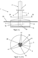
- FIG. 1a shows a first embodiment of a marine structure according to the invention, generally indicated by the reference numeral 1.
- the marine structure 1 comprises a sub-structure 2 and a float element 3.
- the sub-structure 2 comprises a leg 4 having a foot 5.
- the leg 4 has a first buoyancy means 4a, for instance air chambers or such, within a lower part of the leg 4 and foot 5 to provide a first buoyancy to the marine structure 1. This first buoyancy is sufficient to keep the sub-structure 2 afloat.
- the first buoyancy means 4a can be ballasted, for instance by introduction of water, concrete or other material, to decrease the first buoyancy to a level where the sub-structure 2 sinks in the water.
- the float element 3 has a second buoyancy means 3a, for instance air chambers or such, to provide a second buoyancy to the float element 3.
- the second buoyancy is sufficient to keep the float element 2 afloat.
- the second buoyancy means 3a can be ballasted, for instance by introduction of water, concrete or other material, to decrease the second buoyancy to a level where the float element 3 sinks in the water.
- the combined buoyancy of the first buoyancy and the second buoyancy is sufficient to keep the marine structure 1 floating in the sea.
- the sea level is for instance indicated by 50.
- the marine structure 1 is self-floating, i.e. no other means have to be provided to keep the marine structure 1 floating on the sea.
- the float element 3 has a substantially cylindrical symmetrical shape and comprises a cylindrical bottom part 6 and a sleeve or tube shaped top part 7.
- the float element 3 comprises a passage 8 through which the leg 4 extends from above the float element to the foot 4. In the passage 8 the leg 4 is enclosed in the horizontal plane, so that the combination of passage 8 and the leg 4 only allows movements of the leg 4 with respect to the float element 3 in the substantially vertical direction.
- the top part 7 may be omitted.
- the leg 4 can freely move in a substantially vertical direction with respect to the float element 3, although in the shown embodiment downward movement of the float element 3 with respect to the leg 4 is limited by the foot 5. In all other directions movement of the float element 3 with respect to the leg 4 is constrained by the passage 8 in the float element.
- a braking device 9 is provided to provide a braking force between the leg 4 and the float element 3. With this braking device 9 relative movement between leg 4 and float element 3 can be stopped or controlled more accurately. For instance, during transport of the marine structure 1 towards the installation location, it may be desirable that no movement is possible between leg 4 and float element 9.
- the braking device 9 may comprise a control device to control the braking force provided by the braking device 9. When desired multiple braking devices 9 may be provided, which are preferably divided over the circumference of the passage 8.
- the braking device 9 may for instance comprise a number of braking members, for instance rubber pads, which can be forced against the outer surface of the leg 4 by one or more hydraulic cylinders of the braking device 9.
- a locking device may be provided to lock the leg in the transportation position, as shown in Figure 1a , or any other desirable position.
- Figure 1b shows a possible embodiment of a linear guiding arrangement to be used for the linear guiding of the float element 3 and the leg 4 with respect to each other.
- the leg 4 comprises three first guiding elements 40 arranged around the circumference of the leg 4.
- the guiding elements 40 are placed between pairs of second guiding elements 41 arranged at the inner surface of the passage 8.
- the combination of first and second guiding elements 40, 41 provides a relative and reliable guiding device to make linear movement of the leg 4 and the float element 3 with respect to each other in the substantially vertical direction possible.
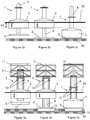
- FIGS 2a, 2b and 2c show the installation of the marine structure 1 on the bottom of the sea 60.
- the marine structure 1 is self-installing, i.e. no separate lifting equipment is required to install the marine structure at a desired installation location.
- the marine structure 1 is shown floating on the sea, indicated by sea level 50, above an installation location during step 1 of the installation sequence.
- the marine structure 1 is sailed to this installation location while it was floating on its own buoyancy.
- the leg 4 is lowered until the foot 5 comes to rest on the bottom of the sea 60.
- the marine structure 1 is stabilized by the presence of the float element 3 enclosing the leg 3.
- the leg 4 can be lowered by ballasting the first buoyancy means 6 so that the first buoyancy becomes negative and the sub-structure 2 sinks into the sea.
- the first buoyancy means are positioned below a wave zone 51, so that heave action on the first buoyancy means are minimized.
- the second buoyancy means 3a of the float element 3 may be ballasted so that it also sinks into the sea.
- the float element 3 is guided by the leg 4. Since this leg 4 now rests on the bottom of the sea 60, the leg 4 provides stability to the float element 3. As a result, the float element 3 may be completely submerged during a part of the downwards movement of the float element 3, while at the same time stability of the marine structure is maintained.
- Figure 2c shows the marine structure in the installed position after lowering of the float element 3.
- the base formed by float element 3 and leg 4 may completely be held on the ground by gravity forces acting on the base.
- extra measures may be provided to anchor the base on the bottom of the sea.
- one or more tilting devices may be provided to tilt the marine structure in an upright position, for instance when the bottom of the sea is not completely flat.
- the bottom of the sea may be flattened before installation of the marine structure 1, or the foot 4 may be adapted to the bottom of the sea.
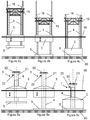
- FIGS. 3a, 3b, and 3c show the installation of a second embodiment of a marine structure 1 according to the invention.
- the same reference numerals have been used for the same parts or parts having substantially the same function.
- a work platform 11 is provided.
- the work platform 11 is movable with respect to the leg 4 between a pre-installation or transport position and an after-installation position.
- lifting devices 12 are provided to move the sub-structure 2 with respect to the float element 3 or to control this movement more accurately.
- the sub-structure 2 and the float element 3 cannot move freely with respect to each other since the lifting devices 12 are arranged between the sub-structure 2 and the float element 3 when activated.
- the lifting devices may for instance be strand jack systems or winches.
- the lifting devices 12 are not used to exert a lifting force from top of the top part 7 of the float element to the foot 5, and to exert a lifting force from the top of the leg 4 to the top of the sleeve 7.
- the lifting devices 12 or similar devices may be provided to only lift one of the leg 4 and float element 3 with respect of the other.
- the bottom side of the foot 5 is provided with downwardly extending skirts 13 forming a matrix of suction spaces. These suction spaces may each be connected to a vacuum system to draw air/water from these spaces.
- the foot 15 When the foot 15 is arranged on the bottom of the sea the foot can be drawn into the ground by applying a vacuum in the suction spaces. By applying different vacuum levels in different suction spaces, the orientation of the marine structure may be corrected.
- Figure 3a shows the marine structure 1 in the transportation position and the first step of the installation procedure.
- the bottom of the platform 11 is at substantially the same height as the top of the top part 7, and the foot 5 is arranged against the float element 3.
- the leg 4 is lowered by ballasting the first buoyancy means 4a.
- the lifting devices 12 will not be used to allow the vertical heave motion of the float element 3.
- the work platform 11 is supported on the top part 7 so that it does not move downwards with the leg 4.
- the first buoyancy means 4a will be arranged below the wave zone such that little heave action is exerted on the leg 4.
- the skirts may be pushed partly into the soil due to the weight of the sub-structure 2.
- the leg 4 may be pulled further into the ground and possibly be tilted to the desired vertical orientation.
- Figure 3b shows the marine structure 1 with the leg 4 in the installed position. Subsequently, the float element 3 may be lowered by combination of ballasting the buoyancy means 3a and/or by actuation of the lifting devices 12 to lower the float element 3 with respect to the sub-structure 2.
- the work platform 11 Before the float element 3 is lowered, the work platform 11 is connected to the leg 4 instead of the top part 7 of the float element 3. As a result, the work platform 11 will be arranged on a top part of the leg 4.
- Figure 3c shows the marine structure 1 in installed position.
- the float element 3 is lowered and rest on the foot 5. From comparison of Figures 3a and 3c it is clear that the work platform 11 is arranged at a higher level with respect to the rest of the marine structure 1 in the installed position when compared with the transportation position.
- the advantage of a relative low position during transport is that the marine structure 1 floating on the sea is more stable.
- a relative high position after installation requires a lower marine structure 1, which is advantageous in view of the costs.
- Another advantage of this installation method is the low vertical motion of the foot 5 during touch down on the bottom.
- This feature will embody the intention of the invention to improved the capability to withstand wave-induced forces and motions during installation.
- a vertical double arrow is drawn to indicate the heave motion of float element 3 induced by wave action.
- foot 5 and leg 4 no vertical arrow has been drawn to indicate that this part of the structure is not heaving induced by wave action.
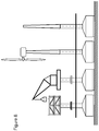
- Figures 4a, 4b and 4c show the installation of another embodiment of the marine structure 1 not according to the invention.
- four legs 4 are provided in four corner areas of the marine structure 1. All four legs 4 are enclosed by the float element 3, and connected to a common foot 5. The legs 4 and the float element 3 can only be moved in a substantially vertical direction with respect to each other.
- a platform 15 is fixed to the upper part of the legs 4, and lifting devices 16 are provided to move or control movement of the float element 3 with respect to the legs 4.
- the float element 3 is free to heave as indicated by the double arrow.
- the buoyancy means of the legs 4 are at least during a second part of the downwards movement of the leg 4 towards the installation position and in the installation position arranged below the wave zone such that little heave action is exerted on the legs 4.
- FIG. 5a, 5b and 5c show the installation of another alternative embodiment of a marine structure 1 according to the invention.
- a platform 20 is arranged on the top part 7 of the float element 3.
- the platform 20, the passage 8 and the top end of the leg 4 delimit a space 21.
- This closed space 21 can be used for moving and/ or controlling movement of the float element 3 and the leg 4 with respect to each other.
- a valve 22 is provided to connect a pressure and/or vacuum pump (not shown) to increase or decrease the pressure in the space 21.
- a pressure and/or vacuum pump not shown
- By increasing the pressure in the space 21 the leg 4 may be pressed downwards with respect to the float element 3.
- By creating a relative low pressure in the space 21 the float element 3 may be pulled downwards with respect to the leg 4.
- the space 21 may be used during installation of the marine structure 1.
- the leg 4 and the float element 3 are arranged in the position shown in Figure 5a .
- the leg 4 When the marine structure 1 is located at an installation location, the leg 4 may be lowered with respect to the float element 3 by ballasting of the leg 4. At the same time air may be pumped into the space 21 to let the leg 4 move downwards in a controlled manner.
- the float element 3 may be lowered with respect to the leg 4. This movement can be created by ballasting the float element 3 and, simultaneously by pumping air out of the space 21 to control the downwards movement of the float element 3.
- the installed position is shown in Figure 5c .
- the float element During lowering of the leg 4 and the foot 5, the float element is free to heave as indicated by the vertical double arrow in drawing 5a and 5b.
- the buoyancy means of the leg 4 are at least during a second part of the downwards movement of the leg 4 towards the installation position and in the installation position arranged below the wave zone such that little heave action is exerted on the leg 4.
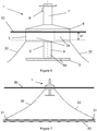
- Figure 6 shows the embodiment of Figure 1 a in a second installation position, wherein the marine structure 1 keeps floating on the sea surface 50 after installation.
- Figure 7 shows that the marine structure 1 for instance may be anchored via anchor cables 30 to anchor points 31 arranged at the bottom of the sea 60 to maintain the marine structure 1 at the installation location.
- Figure 1 a shows the marine structure 1 floating on the sea before installation, i.e. in a pre-installation position.
- the marine structure 1 is sailed to the installation location, and the foot 5 of the leg 4 is lowered to a semi-submerged position, for instance by decreasing the buoyancy of the first buoyancy means 4a.
- the leg 4 may for instance be lowered by unlocking the leg 4 from a fixed position with respect to the float element 3. Any other suitable method or combination of methods may also be used.
- the float element 6 In the installation position, the float element 6 is kept at sea level 50 to provide stability against tilting of the marine structure 1. Since the float element 3 is cylindrically symmetric the float element 3 may provide the same stability in all horizontal directions.
- the sub-structure 2 and the float element 3 are freely movable with respect to each other in the substantially vertical direction.
- the first buoyancy of the sub-structure is sufficient to keep the sub-structure 2 afloat
- the second buoyancy of the float element 3 is sufficient to keep the float element 3 afloat.
- the first buoyancy means of the leg 4 are arranged below a wave zone 51, so that there is little influence of heave action on the sub-structure 2.
- the advantage of the foot 5 of the leg 4 being brought into such semi-submerged position is that it is less influenced by heave of the sea.
- any utility element provided on the sub-structure 2 is relative stable in the sea and is not or less influenced by heave.
- Figures 8 and 9 show different applications of the marine structure of the invention.
- the different applications may be part of the marine structure or may be arranged on the marine structure after installation of the marine structure at an installation location.
- Figure 8 shows different applications of a marine structure arranged on the bottom of the sea.
- the marine structure may comprise all parts of the marine structure of Figure 1 a. From left to right the following applications are shown: an offshore platform, a work platform, a wind turbine, and a meteo mast.
- FIG 9 shows different applications of a marine structure floating on the sea.
- the marine structure may comprise all parts of the marine structure of Figure 6 . From left to right the following applications are shown: an offshore platform, a work platform, a wind turbine, and a meteo mast, or a wave energy converter.
- the relative movement of the float element with respect to the leg caused by heave is used to generate usable energy, preferably storable energy, such as electrical energy.
- marine structure 1 of the invention may also be used for any other suitable application.
Landscapes
- Engineering & Computer Science (AREA)
- General Engineering & Computer Science (AREA)
- Civil Engineering (AREA)
- Structural Engineering (AREA)
- Mechanical Engineering (AREA)
- Architecture (AREA)
- Chemical & Material Sciences (AREA)
- Combustion & Propulsion (AREA)
- Ocean & Marine Engineering (AREA)
- Other Liquid Machine Or Engine Such As Wave Power Use (AREA)
- Revetment (AREA)
Claims (15)
- Structure marine flottante (1) comprenant :une sous-structure (2) comprenant une jambe unique (4) et un pied (5) à l'extrémité inférieure de la jambe (4), la jambe unique (4) ayant un premier moyen de flottabilité (4a) agencé dans une partie inférieure de la jambe pour fournir une première flottabilité, dans laquelle la première flottabilité est suffisante pour maintenir la sous-structure hors de l'eau, et dans laquelle le premier moyen de flottabilité peut être lesté pour réduire la flottabilité de la jambe, etun élément de flotteur (3) ayant un second moyen de flottabilité (3a) pour fournir une seconde flottabilité, dans laquelle la seconde flottabilité est suffisante pour maintenir l'élément de flotteur hors de l'eau, et dans laquelle le second moyen de flottabilité peut être lesté pour réduire la flottabilité de l'élément de flotteur,dans laquelle la sous-structure (2) et l'élément de flotteur (3) sont construits pour permettre un mouvement induit par les vagues relatif l'un par rapport à l'autre dans une direction sensiblement verticale,la construction étant un agencement de guidage linéaire (40, 41) dans un passage (8) dans l'élément de flotteur (3) à travers lequel la jambe (4) s'étend depuis le dessus de l'élément de flotteur (3) jusqu'au pied (5),dans lequel la jambe (4) est mobile d'une position de pré-installation à une position d'installation par un mouvement sensiblement descendant de la jambe par rapport à l'élément de flotteur (3), et dans laquelle pendant au moins une seconde partie du mouvement descendant de la jambe (4) vers la position d'installation et/ou dans la position d'installation, les premiers moyens de flottabilité (4a) sont sensiblement positionnés au-dessous d'une zone de vagues pour réduire sensiblement l'action de la houle sur les premiers moyens de flottabilité.
- Structure marine flottante (1) selon la revendication 1, dans laquelle l'élément de flotteur (3) est une partie permanente de la structure marine (1).
- Structure marine flottante (1) selon l'une quelconque des revendications précédentes, dans laquelle l'élément de flotteur (3) entoure la jambe (4) .
- Structure marine flottante (1) selon l'une quelconque des revendications précédentes, dans laquelle l'élément de flotteur (3) est configuré pour être lesté pendant l'installation et devenir un élément de lest d'une base de la structure marine (1).
- Structure marine flottante (1) selon l'une quelconque des revendications précédentes, dans laquelle le pied (5) doit être agencé au fond de la mer.
- Structure marine flottante (1) selon l'une quelconque des revendications précédentes, dans laquelle la structure marine (1) comprend un dispositif de freinage (9) pour fournir la force de freinage entre la sous-structure (2) et l'élément de flotteur (3) .
- Structure marine flottante (1) selon l'une quelconque des revendications précédentes, dans laquelle la sous-structure (2) comprend une plateforme (11, 20) mobile par rapport à la jambe (4) dans la direction sensiblement verticale.
- Structure marine flottante (1) selon l'une quelconque des revendications précédentes, dans laquelle la structure marine comprend une plateforme en mer, une plateforme de travail, une turbine, un poteau météorologique ou un convertisseur d'énergie des vagues.
- Structure marine flottante (1) selon l'une quelconque des revendications précédentes, dans laquelle la structure marine (1) comprend un ou plusieurs espaces fermés (21) entre la sous-structure (2) et l'élément de flotteur (3), dans laquelle la pression dans les un ou plusieurs espaces peut être utilisée pour déplacer ou contrôler le mouvement de la sous-structure et l'élément de flotteur l'un par rapport à l'autre.
- Procédé pour installer une structure marine (1) selon l'une quelconque des revendications précédentes, comprenant les étapes consistant à :faire naviguer la structure marine (1) jusqu'à un emplacement d'installation, etfaire descendre la jambe (4) par rapport à l'élément de flotteur jusqu'à une position d'installation de la jambe, dans lequel pendant au moins une seconde partie du mouvement descendant de la jambe vers la position d'installation et/ou dans la position d'installation, les premiers moyens de flottabilité (4a) sont sensiblement positionnés au-dessous d'une zone de vagues pour réduire sensiblement l'action de la houle sur les premiers moyens de flottabilité.
- Procédé selon la revendication 10, dans lequel l'étape consistant à faire descendre la jambe comprend l'étape consistant à lester les premiers moyens de flottabilité.
- Procédé selon la revendication 10 ou 11, dans lequel le pied doit être agencé au fond de la mer, et dans lequel l'étape consistant à déplacer la jambe dans la position d'installation comprend l'étape consistant à agencer le pied de la jambe au fond de la mer.
- Procédé selon la revendication 12, comprenant, après que le pied de la jambe a été agencé au fond de la mer, l'étape consistant à faire descendre l'élément de flotteur par rapport à la jambe jusqu'à une position d'installation d'élément de flotteur en lestant l'élément de flotteur.
- Procédé selon la revendication 13, dans lequel l'élément de flotteur (3), pendant l'installation, devient un élément de lest d'une base de la structure marine (1).
- Procédé selon la revendication 14, dans lequel l'élément de flotteur (3), dans sa position d'installation, s' appuie sur le pied (5) de la jambe (4) .
Applications Claiming Priority (2)
| Application Number | Priority Date | Filing Date | Title |
|---|---|---|---|
| NL2005755A NL2005755C2 (en) | 2010-11-25 | 2010-11-25 | Floating marine structure. |
| PCT/NL2011/050803 WO2012070941A2 (fr) | 2010-11-25 | 2011-11-25 | Structure marine flottante |
Publications (2)
| Publication Number | Publication Date |
|---|---|
| EP2643210A2 EP2643210A2 (fr) | 2013-10-02 |
| EP2643210B1 true EP2643210B1 (fr) | 2017-10-11 |
Family
ID=44227974
Family Applications (1)
| Application Number | Title | Priority Date | Filing Date |
|---|---|---|---|
| EP11791640.3A Active EP2643210B1 (fr) | 2010-11-25 | 2011-11-25 | Structure marine flottante |
Country Status (5)
| Country | Link |
|---|---|
| US (1) | US9499240B2 (fr) |
| EP (1) | EP2643210B1 (fr) |
| NL (1) | NL2005755C2 (fr) |
| NO (1) | NO2643210T3 (fr) |
| WO (1) | WO2012070941A2 (fr) |
Cited By (2)
| Publication number | Priority date | Publication date | Assignee | Title |
|---|---|---|---|---|
| NO20190847A1 (en) * | 2019-07-04 | 2021-01-05 | Newtech As | A floating foundation for an offshore wind turbine, a system for extracting energy from wind, and a method of installing a wind turbine |
| WO2023006955A1 (fr) | 2021-07-30 | 2023-02-02 | Lak Mohammad Amin | Fondation basée sur la gravité |
Families Citing this family (12)
| Publication number | Priority date | Publication date | Assignee | Title |
|---|---|---|---|---|
| WO2016014947A2 (fr) | 2014-07-24 | 2016-01-28 | Oscilla Power Inc. | Procédé permettant de déployer et de récupérer un convertisseur d'énergie des vagues |
| EP3172432B1 (fr) * | 2014-07-24 | 2020-04-08 | Oscilla Power Inc. | Procédé permettant de déployer et de récupérer un convertisseur d'énergie des vagues |
| FR3035455B1 (fr) * | 2015-04-22 | 2018-10-05 | IFP Energies Nouvelles | Support flottant avec section horizontale variable avec la profondeur |
| KR101723987B1 (ko) * | 2015-09-22 | 2017-04-06 | 한국전력공사 | 해양 지지체 및 그 시공방법 |
| US11173987B2 (en) * | 2016-10-18 | 2021-11-16 | Atkins Energy, Inc. | Offshore floating structures |
| US10302068B2 (en) * | 2016-10-31 | 2019-05-28 | Zentech, Inc. | Conversion of movable offshore drilling structure to wind turbine application |
| US10352010B2 (en) * | 2017-02-13 | 2019-07-16 | Saudi Arabian Oil Company | Self-installing offshore platform |
| ES2785802B2 (es) * | 2019-04-05 | 2021-05-19 | Esteyco S A | Procedimiento de instalacion de un aerogenerador de torre mar adentro |
| CN212099278U (zh) * | 2020-03-25 | 2020-12-08 | 上海惠生海洋工程有限公司 | 一种浅水自安装平台 |
| US11685486B2 (en) | 2021-01-14 | 2023-06-27 | Saudi Arabian Oil Company | Resilient bumper and bumper system |
| CN113756356A (zh) * | 2021-07-26 | 2021-12-07 | 中国电建集团华东勘测设计研究院有限公司 | 一种浮筒重力式基础的海上风机一步式整体化安装装置、系统及方法 |
| NL2031193B1 (en) * | 2022-03-09 | 2023-09-18 | Deawoo Eng & Construction Co Ltd | Marine structure and method |
Family Cites Families (13)
| Publication number | Priority date | Publication date | Assignee | Title |
|---|---|---|---|---|
| US3118283A (en) * | 1964-01-21 | Xkilling barge | ||
| US3001370A (en) * | 1954-09-23 | 1961-09-26 | John B Templeton | Marine drilling methods and apparatus |
| US2953904A (en) | 1958-04-03 | 1960-09-27 | Lowell B Christenson | Submersible barge assembly |
| GB1169262A (en) * | 1965-08-10 | 1969-11-05 | Vickers Ltd | Improved floatable vessel |
| US3996754A (en) * | 1973-12-14 | 1976-12-14 | Engineering Technology Analysts, Inc. | Mobile marine drilling unit |
| DE2457536C3 (de) * | 1974-12-03 | 1978-03-09 | Philipp Holzmann Ag, 6000 Frankfurt | Verfahren zum Transport und zum Absetzen einer Offshore-Plattform auf der Meeressohle sowie Offshore-Plattform |
| US4451174A (en) * | 1983-02-07 | 1984-05-29 | Global Marine Inc. | Monopod jackup drilling system |
| US4627767A (en) * | 1983-07-22 | 1986-12-09 | Santa Fe International Corporation | Mobile sea barge and platform |
| FR2734851B1 (fr) * | 1995-06-02 | 1999-03-05 | Technip Geoproduction | Plate-forme auto-elevatrice de forage ou d'exploitation petroliere en mer. |
| DK0942102T3 (da) * | 1998-03-11 | 2005-01-10 | Technip France | Selvlöftende platform med nedsænket reservoir og fremgangsmåde til anbringelse og ophejsning af reservoiret |
| AU757367B2 (en) | 1998-04-02 | 2003-02-20 | Suction Pile Technology B.V. | Marine structure |
| US7785163B2 (en) | 2008-08-15 | 2010-08-31 | Plasti-Fab Inc. | Wave energy buoy |
| WO2010085970A1 (fr) * | 2009-01-27 | 2010-08-05 | Statoil Asa | Plate-forme mobile en mer |
-
2010
- 2010-11-25 NL NL2005755A patent/NL2005755C2/en not_active IP Right Cessation
-
2011
- 2011-11-25 EP EP11791640.3A patent/EP2643210B1/fr active Active
- 2011-11-25 NO NO11791640A patent/NO2643210T3/no unknown
- 2011-11-25 WO PCT/NL2011/050803 patent/WO2012070941A2/fr active Application Filing
- 2011-11-25 US US13/989,622 patent/US9499240B2/en active Active
Non-Patent Citations (1)
| Title |
|---|
| None * |
Cited By (3)
| Publication number | Priority date | Publication date | Assignee | Title |
|---|---|---|---|---|
| NO20190847A1 (en) * | 2019-07-04 | 2021-01-05 | Newtech As | A floating foundation for an offshore wind turbine, a system for extracting energy from wind, and a method of installing a wind turbine |
| NO346752B1 (en) * | 2019-07-04 | 2022-12-12 | Newtech As | A floating foundation for an offshore wind turbine, a system for extracting energy from wind, and a method of installing a wind turbine |
| WO2023006955A1 (fr) | 2021-07-30 | 2023-02-02 | Lak Mohammad Amin | Fondation basée sur la gravité |
Also Published As
| Publication number | Publication date |
|---|---|
| US9499240B2 (en) | 2016-11-22 |
| EP2643210A2 (fr) | 2013-10-02 |
| US20130298815A1 (en) | 2013-11-14 |
| NL2005755C2 (en) | 2012-05-29 |
| NO2643210T3 (fr) | 2018-03-10 |
| WO2012070941A3 (fr) | 2012-07-19 |
| WO2012070941A2 (fr) | 2012-05-31 |
Similar Documents
| Publication | Publication Date | Title |
|---|---|---|
| EP2643210B1 (fr) | Structure marine flottante | |
| KR101399983B1 (ko) | 근해 풍력 기지 산업에 이용하기 위한 지지 구조물 | |
| EP3430259B1 (fr) | Turbine éolienne flottante et procédé permettant l'installation d'une telle turbine éolienne flottante | |
| US9758941B2 (en) | Offshore tower for drilling and/or production | |
| GB2378679A (en) | Floating offshore wind turbine | |
| EP2596240B1 (fr) | Structure de support d'eolienne offshore | |
| CN103228909A (zh) | 用于安装海上塔的方法 | |
| US8899881B2 (en) | Offshore tower for drilling and/or production | |
| KR102144423B1 (ko) | 반잠수식 풍력발전기 및 이의 설치 및 해체 방법 | |
| CN107630461B (zh) | 一种组合式海上四浮筒浮箱基础结构及其施工方法 | |
| WO2014205603A1 (fr) | Plate-forme pour turbines marémotrices | |
| CN105460175A (zh) | 一种浅水沉底式单柱型平台 | |
| CN101837929A (zh) | 一种在滩涂区域驳船吊装风机的作业方法 | |
| KR102192116B1 (ko) | 스파형 풍력발전기 및 이의 설치 및 해체 방법 | |
| US10352010B2 (en) | Self-installing offshore platform | |
| CN203473217U (zh) | 一种海上平台定位柱的支撑杆 | |
| CN115704209A (zh) | 一种浅水域海上平台安装方法 | |
| AU2021202442B2 (en) | Gravity-Based Structure For Off-Shore Structures | |
| NL2031193B1 (en) | Marine structure and method | |
| TWI834746B (zh) | 具備起重機之作業台船及其起重機運用方法 | |
| CN213328975U (zh) | 一种半潜插桩式海洋起重施工平台 | |
| KR102645338B1 (ko) | 해저공간 플랫폼 승강시스템 | |
| CN211646452U (zh) | 一种风机基础及风机 | |
| TW202106602A (zh) | 具備塔式起重機之作業船及其起重機運用方法 | |
| CN203473199U (zh) | 海上平台的定位柱 |
Legal Events
| Date | Code | Title | Description |
|---|---|---|---|
| PUAI | Public reference made under article 153(3) epc to a published international application that has entered the european phase |
Free format text: ORIGINAL CODE: 0009012 |
|
| 17P | Request for examination filed |
Effective date: 20130624 |
|
| AK | Designated contracting states |
Kind code of ref document: A2 Designated state(s): AL AT BE BG CH CY CZ DE DK EE ES FI FR GB GR HR HU IE IS IT LI LT LU LV MC MK MT NL NO PL PT RO RS SE SI SK SM TR |
|
| DAX | Request for extension of the european patent (deleted) | ||
| 17Q | First examination report despatched |
Effective date: 20140526 |
|
| GRAP | Despatch of communication of intention to grant a patent |
Free format text: ORIGINAL CODE: EPIDOSNIGR1 |
|
| INTG | Intention to grant announced |
Effective date: 20161221 |
|
| GRAJ | Information related to disapproval of communication of intention to grant by the applicant or resumption of examination proceedings by the epo deleted |
Free format text: ORIGINAL CODE: EPIDOSDIGR1 |
|
| GRAP | Despatch of communication of intention to grant a patent |
Free format text: ORIGINAL CODE: EPIDOSNIGR1 |
|
| INTC | Intention to grant announced (deleted) | ||
| INTG | Intention to grant announced |
Effective date: 20170531 |
|
| GRAS | Grant fee paid |
Free format text: ORIGINAL CODE: EPIDOSNIGR3 |
|
| GRAA | (expected) grant |
Free format text: ORIGINAL CODE: 0009210 |
|
| AK | Designated contracting states |
Kind code of ref document: B1 Designated state(s): AL AT BE BG CH CY CZ DE DK EE ES FI FR GB GR HR HU IE IS IT LI LT LU LV MC MK MT NL NO PL PT RO RS SE SI SK SM TR |
|
| REG | Reference to a national code |
Ref country code: GB Ref legal event code: FG4D |
|
| REG | Reference to a national code |
Ref country code: CH Ref legal event code: EP |
|
| REG | Reference to a national code |
Ref country code: IE Ref legal event code: FG4D |
|
| REG | Reference to a national code |
Ref country code: AT Ref legal event code: REF Ref document number: 935770 Country of ref document: AT Kind code of ref document: T Effective date: 20171115 |
|
| REG | Reference to a national code |
Ref country code: DE Ref legal event code: R096 Ref document number: 602011042357 Country of ref document: DE |
|
| REG | Reference to a national code |
Ref country code: FR Ref legal event code: PLFP Year of fee payment: 7 |
|
| REG | Reference to a national code |
Ref country code: NL Ref legal event code: FP |
|
| REG | Reference to a national code |
Ref country code: LT Ref legal event code: MG4D |
|
| REG | Reference to a national code |
Ref country code: NO Ref legal event code: T2 Effective date: 20171011 |
|
| REG | Reference to a national code |
Ref country code: AT Ref legal event code: MK05 Ref document number: 935770 Country of ref document: AT Kind code of ref document: T Effective date: 20171011 |
|
| PG25 | Lapsed in a contracting state [announced via postgrant information from national office to epo] |
Ref country code: ES Free format text: LAPSE BECAUSE OF FAILURE TO SUBMIT A TRANSLATION OF THE DESCRIPTION OR TO PAY THE FEE WITHIN THE PRESCRIBED TIME-LIMIT Effective date: 20171011 Ref country code: SE Free format text: LAPSE BECAUSE OF FAILURE TO SUBMIT A TRANSLATION OF THE DESCRIPTION OR TO PAY THE FEE WITHIN THE PRESCRIBED TIME-LIMIT Effective date: 20171011 Ref country code: LT Free format text: LAPSE BECAUSE OF FAILURE TO SUBMIT A TRANSLATION OF THE DESCRIPTION OR TO PAY THE FEE WITHIN THE PRESCRIBED TIME-LIMIT Effective date: 20171011 Ref country code: FI Free format text: LAPSE BECAUSE OF FAILURE TO SUBMIT A TRANSLATION OF THE DESCRIPTION OR TO PAY THE FEE WITHIN THE PRESCRIBED TIME-LIMIT Effective date: 20171011 |
|
| PG25 | Lapsed in a contracting state [announced via postgrant information from national office to epo] |
Ref country code: AT Free format text: LAPSE BECAUSE OF FAILURE TO SUBMIT A TRANSLATION OF THE DESCRIPTION OR TO PAY THE FEE WITHIN THE PRESCRIBED TIME-LIMIT Effective date: 20171011 Ref country code: GR Free format text: LAPSE BECAUSE OF FAILURE TO SUBMIT A TRANSLATION OF THE DESCRIPTION OR TO PAY THE FEE WITHIN THE PRESCRIBED TIME-LIMIT Effective date: 20180112 Ref country code: RS Free format text: LAPSE BECAUSE OF FAILURE TO SUBMIT A TRANSLATION OF THE DESCRIPTION OR TO PAY THE FEE WITHIN THE PRESCRIBED TIME-LIMIT Effective date: 20171011 Ref country code: HR Free format text: LAPSE BECAUSE OF FAILURE TO SUBMIT A TRANSLATION OF THE DESCRIPTION OR TO PAY THE FEE WITHIN THE PRESCRIBED TIME-LIMIT Effective date: 20171011 Ref country code: LV Free format text: LAPSE BECAUSE OF FAILURE TO SUBMIT A TRANSLATION OF THE DESCRIPTION OR TO PAY THE FEE WITHIN THE PRESCRIBED TIME-LIMIT Effective date: 20171011 Ref country code: BG Free format text: LAPSE BECAUSE OF FAILURE TO SUBMIT A TRANSLATION OF THE DESCRIPTION OR TO PAY THE FEE WITHIN THE PRESCRIBED TIME-LIMIT Effective date: 20180111 Ref country code: IS Free format text: LAPSE BECAUSE OF FAILURE TO SUBMIT A TRANSLATION OF THE DESCRIPTION OR TO PAY THE FEE WITHIN THE PRESCRIBED TIME-LIMIT Effective date: 20180211 |
|
| REG | Reference to a national code |
Ref country code: DE Ref legal event code: R097 Ref document number: 602011042357 Country of ref document: DE |
|
| PG25 | Lapsed in a contracting state [announced via postgrant information from national office to epo] |
Ref country code: LI Free format text: LAPSE BECAUSE OF NON-PAYMENT OF DUE FEES Effective date: 20171130 Ref country code: CH Free format text: LAPSE BECAUSE OF NON-PAYMENT OF DUE FEES Effective date: 20171130 Ref country code: SK Free format text: LAPSE BECAUSE OF FAILURE TO SUBMIT A TRANSLATION OF THE DESCRIPTION OR TO PAY THE FEE WITHIN THE PRESCRIBED TIME-LIMIT Effective date: 20171011 Ref country code: MC Free format text: LAPSE BECAUSE OF FAILURE TO SUBMIT A TRANSLATION OF THE DESCRIPTION OR TO PAY THE FEE WITHIN THE PRESCRIBED TIME-LIMIT Effective date: 20171011 Ref country code: DK Free format text: LAPSE BECAUSE OF FAILURE TO SUBMIT A TRANSLATION OF THE DESCRIPTION OR TO PAY THE FEE WITHIN THE PRESCRIBED TIME-LIMIT Effective date: 20171011 Ref country code: CZ Free format text: LAPSE BECAUSE OF FAILURE TO SUBMIT A TRANSLATION OF THE DESCRIPTION OR TO PAY THE FEE WITHIN THE PRESCRIBED TIME-LIMIT Effective date: 20171011 Ref country code: EE Free format text: LAPSE BECAUSE OF FAILURE TO SUBMIT A TRANSLATION OF THE DESCRIPTION OR TO PAY THE FEE WITHIN THE PRESCRIBED TIME-LIMIT Effective date: 20171011 |
|
| PLBE | No opposition filed within time limit |
Free format text: ORIGINAL CODE: 0009261 |
|
| STAA | Information on the status of an ep patent application or granted ep patent |
Free format text: STATUS: NO OPPOSITION FILED WITHIN TIME LIMIT |
|
| PG25 | Lapsed in a contracting state [announced via postgrant information from national office to epo] |
Ref country code: SM Free format text: LAPSE BECAUSE OF FAILURE TO SUBMIT A TRANSLATION OF THE DESCRIPTION OR TO PAY THE FEE WITHIN THE PRESCRIBED TIME-LIMIT Effective date: 20171011 Ref country code: PL Free format text: LAPSE BECAUSE OF FAILURE TO SUBMIT A TRANSLATION OF THE DESCRIPTION OR TO PAY THE FEE WITHIN THE PRESCRIBED TIME-LIMIT Effective date: 20171011 Ref country code: LU Free format text: LAPSE BECAUSE OF NON-PAYMENT OF DUE FEES Effective date: 20171125 Ref country code: RO Free format text: LAPSE BECAUSE OF FAILURE TO SUBMIT A TRANSLATION OF THE DESCRIPTION OR TO PAY THE FEE WITHIN THE PRESCRIBED TIME-LIMIT Effective date: 20171011 Ref country code: IT Free format text: LAPSE BECAUSE OF FAILURE TO SUBMIT A TRANSLATION OF THE DESCRIPTION OR TO PAY THE FEE WITHIN THE PRESCRIBED TIME-LIMIT Effective date: 20171011 |
|
| REG | Reference to a national code |
Ref country code: BE Ref legal event code: MM Effective date: 20171130 |
|
| 26N | No opposition filed |
Effective date: 20180712 |
|
| PG25 | Lapsed in a contracting state [announced via postgrant information from national office to epo] |
Ref country code: MT Free format text: LAPSE BECAUSE OF NON-PAYMENT OF DUE FEES Effective date: 20171125 |
|
| PG25 | Lapsed in a contracting state [announced via postgrant information from national office to epo] |
Ref country code: SI Free format text: LAPSE BECAUSE OF FAILURE TO SUBMIT A TRANSLATION OF THE DESCRIPTION OR TO PAY THE FEE WITHIN THE PRESCRIBED TIME-LIMIT Effective date: 20171011 Ref country code: BE Free format text: LAPSE BECAUSE OF NON-PAYMENT OF DUE FEES Effective date: 20171130 |
|
| PG25 | Lapsed in a contracting state [announced via postgrant information from national office to epo] |
Ref country code: HU Free format text: LAPSE BECAUSE OF FAILURE TO SUBMIT A TRANSLATION OF THE DESCRIPTION OR TO PAY THE FEE WITHIN THE PRESCRIBED TIME-LIMIT; INVALID AB INITIO Effective date: 20111125 |
|
| PG25 | Lapsed in a contracting state [announced via postgrant information from national office to epo] |
Ref country code: CY Free format text: LAPSE BECAUSE OF NON-PAYMENT OF DUE FEES Effective date: 20171011 |
|
| PG25 | Lapsed in a contracting state [announced via postgrant information from national office to epo] |
Ref country code: MK Free format text: LAPSE BECAUSE OF FAILURE TO SUBMIT A TRANSLATION OF THE DESCRIPTION OR TO PAY THE FEE WITHIN THE PRESCRIBED TIME-LIMIT Effective date: 20171011 |
|
| PG25 | Lapsed in a contracting state [announced via postgrant information from national office to epo] |
Ref country code: TR Free format text: LAPSE BECAUSE OF FAILURE TO SUBMIT A TRANSLATION OF THE DESCRIPTION OR TO PAY THE FEE WITHIN THE PRESCRIBED TIME-LIMIT Effective date: 20171011 |
|
| PG25 | Lapsed in a contracting state [announced via postgrant information from national office to epo] |
Ref country code: PT Free format text: LAPSE BECAUSE OF FAILURE TO SUBMIT A TRANSLATION OF THE DESCRIPTION OR TO PAY THE FEE WITHIN THE PRESCRIBED TIME-LIMIT Effective date: 20171011 |
|
| PG25 | Lapsed in a contracting state [announced via postgrant information from national office to epo] |
Ref country code: AL Free format text: LAPSE BECAUSE OF FAILURE TO SUBMIT A TRANSLATION OF THE DESCRIPTION OR TO PAY THE FEE WITHIN THE PRESCRIBED TIME-LIMIT Effective date: 20171011 |
|
| PGFP | Annual fee paid to national office [announced via postgrant information from national office to epo] |
Ref country code: NO Payment date: 20221125 Year of fee payment: 12 Ref country code: NL Payment date: 20221123 Year of fee payment: 12 Ref country code: FR Payment date: 20221123 Year of fee payment: 12 Ref country code: DE Payment date: 20221122 Year of fee payment: 12 |
|
| PGFP | Annual fee paid to national office [announced via postgrant information from national office to epo] |
Ref country code: GB Payment date: 20231123 Year of fee payment: 13 |
|
| PGFP | Annual fee paid to national office [announced via postgrant information from national office to epo] |
Ref country code: IE Payment date: 20231117 Year of fee payment: 13 |