EP2642761A2 - Dispositif et méthode pour afficher des images tri-dimensionnelles - Google Patents
Dispositif et méthode pour afficher des images tri-dimensionnelles Download PDFInfo
- Publication number
- EP2642761A2 EP2642761A2 EP13155571.6A EP13155571A EP2642761A2 EP 2642761 A2 EP2642761 A2 EP 2642761A2 EP 13155571 A EP13155571 A EP 13155571A EP 2642761 A2 EP2642761 A2 EP 2642761A2
- Authority
- EP
- European Patent Office
- Prior art keywords
- image
- light
- converted
- display panel
- display apparatus
- Prior art date
- Legal status (The legal status is an assumption and is not a legal conclusion. Google has not performed a legal analysis and makes no representation as to the accuracy of the status listed.)
- Withdrawn
Links
Images


Classifications
-
- G—PHYSICS
- G09—EDUCATION; CRYPTOGRAPHY; DISPLAY; ADVERTISING; SEALS
- G09G—ARRANGEMENTS OR CIRCUITS FOR CONTROL OF INDICATING DEVICES USING STATIC MEANS TO PRESENT VARIABLE INFORMATION
- G09G3/00—Control arrangements or circuits, of interest only in connection with visual indicators other than cathode-ray tubes
- G09G3/20—Control arrangements or circuits, of interest only in connection with visual indicators other than cathode-ray tubes for presentation of an assembly of a number of characters, e.g. a page, by composing the assembly by combination of individual elements arranged in a matrix no fixed position being assigned to or needed to be assigned to the individual characters or partial characters
- G09G3/34—Control arrangements or circuits, of interest only in connection with visual indicators other than cathode-ray tubes for presentation of an assembly of a number of characters, e.g. a page, by composing the assembly by combination of individual elements arranged in a matrix no fixed position being assigned to or needed to be assigned to the individual characters or partial characters by control of light from an independent source
- G09G3/36—Control arrangements or circuits, of interest only in connection with visual indicators other than cathode-ray tubes for presentation of an assembly of a number of characters, e.g. a page, by composing the assembly by combination of individual elements arranged in a matrix no fixed position being assigned to or needed to be assigned to the individual characters or partial characters by control of light from an independent source using liquid crystals
-
- G—PHYSICS
- G09—EDUCATION; CRYPTOGRAPHY; DISPLAY; ADVERTISING; SEALS
- G09G—ARRANGEMENTS OR CIRCUITS FOR CONTROL OF INDICATING DEVICES USING STATIC MEANS TO PRESENT VARIABLE INFORMATION
- G09G3/00—Control arrangements or circuits, of interest only in connection with visual indicators other than cathode-ray tubes
- G09G3/20—Control arrangements or circuits, of interest only in connection with visual indicators other than cathode-ray tubes for presentation of an assembly of a number of characters, e.g. a page, by composing the assembly by combination of individual elements arranged in a matrix no fixed position being assigned to or needed to be assigned to the individual characters or partial characters
- G09G3/34—Control arrangements or circuits, of interest only in connection with visual indicators other than cathode-ray tubes for presentation of an assembly of a number of characters, e.g. a page, by composing the assembly by combination of individual elements arranged in a matrix no fixed position being assigned to or needed to be assigned to the individual characters or partial characters by control of light from an independent source
- G09G3/3406—Control of illumination source
- G09G3/3413—Details of control of colour illumination sources
-
- H—ELECTRICITY
- H04—ELECTRIC COMMUNICATION TECHNIQUE
- H04N—PICTORIAL COMMUNICATION, e.g. TELEVISION
- H04N13/00—Stereoscopic video systems; Multi-view video systems; Details thereof
- H04N13/10—Processing, recording or transmission of stereoscopic or multi-view image signals
- H04N13/106—Processing image signals
- H04N13/122—Improving the 3D impression of stereoscopic images by modifying image signal contents, e.g. by filtering or adding monoscopic depth cues
- H04N13/125—Improving the 3D impression of stereoscopic images by modifying image signal contents, e.g. by filtering or adding monoscopic depth cues for crosstalk reduction
-
- G—PHYSICS
- G02—OPTICS
- G02B—OPTICAL ELEMENTS, SYSTEMS OR APPARATUS
- G02B30/00—Optical systems or apparatus for producing three-dimensional [3D] effects, e.g. stereoscopic images
- G02B30/20—Optical systems or apparatus for producing three-dimensional [3D] effects, e.g. stereoscopic images by providing first and second parallax images to an observer's left and right eyes
- G02B30/22—Optical systems or apparatus for producing three-dimensional [3D] effects, e.g. stereoscopic images by providing first and second parallax images to an observer's left and right eyes of the stereoscopic type
- G02B30/25—Optical systems or apparatus for producing three-dimensional [3D] effects, e.g. stereoscopic images by providing first and second parallax images to an observer's left and right eyes of the stereoscopic type using polarisation techniques
-
- G—PHYSICS
- G09—EDUCATION; CRYPTOGRAPHY; DISPLAY; ADVERTISING; SEALS
- G09G—ARRANGEMENTS OR CIRCUITS FOR CONTROL OF INDICATING DEVICES USING STATIC MEANS TO PRESENT VARIABLE INFORMATION
- G09G3/00—Control arrangements or circuits, of interest only in connection with visual indicators other than cathode-ray tubes
- G09G3/20—Control arrangements or circuits, of interest only in connection with visual indicators other than cathode-ray tubes for presentation of an assembly of a number of characters, e.g. a page, by composing the assembly by combination of individual elements arranged in a matrix no fixed position being assigned to or needed to be assigned to the individual characters or partial characters
- G09G3/34—Control arrangements or circuits, of interest only in connection with visual indicators other than cathode-ray tubes for presentation of an assembly of a number of characters, e.g. a page, by composing the assembly by combination of individual elements arranged in a matrix no fixed position being assigned to or needed to be assigned to the individual characters or partial characters by control of light from an independent source
- G09G3/36—Control arrangements or circuits, of interest only in connection with visual indicators other than cathode-ray tubes for presentation of an assembly of a number of characters, e.g. a page, by composing the assembly by combination of individual elements arranged in a matrix no fixed position being assigned to or needed to be assigned to the individual characters or partial characters by control of light from an independent source using liquid crystals
- G09G3/3611—Control of matrices with row and column drivers
- G09G3/3648—Control of matrices with row and column drivers using an active matrix
-
- H—ELECTRICITY
- H04—ELECTRIC COMMUNICATION TECHNIQUE
- H04N—PICTORIAL COMMUNICATION, e.g. TELEVISION
- H04N13/00—Stereoscopic video systems; Multi-view video systems; Details thereof
- H04N13/10—Processing, recording or transmission of stereoscopic or multi-view image signals
- H04N13/106—Processing image signals
- H04N13/122—Improving the 3D impression of stereoscopic images by modifying image signal contents, e.g. by filtering or adding monoscopic depth cues
-
- H—ELECTRICITY
- H04—ELECTRIC COMMUNICATION TECHNIQUE
- H04N—PICTORIAL COMMUNICATION, e.g. TELEVISION
- H04N13/00—Stereoscopic video systems; Multi-view video systems; Details thereof
- H04N13/30—Image reproducers
- H04N13/332—Displays for viewing with the aid of special glasses or head-mounted displays [HMD]
- H04N13/341—Displays for viewing with the aid of special glasses or head-mounted displays [HMD] using temporal multiplexing
-
- G—PHYSICS
- G09—EDUCATION; CRYPTOGRAPHY; DISPLAY; ADVERTISING; SEALS
- G09G—ARRANGEMENTS OR CIRCUITS FOR CONTROL OF INDICATING DEVICES USING STATIC MEANS TO PRESENT VARIABLE INFORMATION
- G09G2310/00—Command of the display device
- G09G2310/02—Addressing, scanning or driving the display screen or processing steps related thereto
- G09G2310/0237—Switching ON and OFF the backlight within one frame
-
- G—PHYSICS
- G09—EDUCATION; CRYPTOGRAPHY; DISPLAY; ADVERTISING; SEALS
- G09G—ARRANGEMENTS OR CIRCUITS FOR CONTROL OF INDICATING DEVICES USING STATIC MEANS TO PRESENT VARIABLE INFORMATION
- G09G2310/00—Command of the display device
- G09G2310/02—Addressing, scanning or driving the display screen or processing steps related thereto
- G09G2310/024—Scrolling of light from the illumination source over the display in combination with the scanning of the display screen
-
- G—PHYSICS
- G09—EDUCATION; CRYPTOGRAPHY; DISPLAY; ADVERTISING; SEALS
- G09G—ARRANGEMENTS OR CIRCUITS FOR CONTROL OF INDICATING DEVICES USING STATIC MEANS TO PRESENT VARIABLE INFORMATION
- G09G2320/00—Control of display operating conditions
- G09G2320/02—Improving the quality of display appearance
- G09G2320/0209—Crosstalk reduction, i.e. to reduce direct or indirect influences of signals directed to a certain pixel of the displayed image on other pixels of said image, inclusive of influences affecting pixels in different frames or fields or sub-images which constitute a same image, e.g. left and right images of a stereoscopic display
-
- G—PHYSICS
- G09—EDUCATION; CRYPTOGRAPHY; DISPLAY; ADVERTISING; SEALS
- G09G—ARRANGEMENTS OR CIRCUITS FOR CONTROL OF INDICATING DEVICES USING STATIC MEANS TO PRESENT VARIABLE INFORMATION
- G09G2340/00—Aspects of display data processing
- G09G2340/04—Changes in size, position or resolution of an image
- G09G2340/0407—Resolution change, inclusive of the use of different resolutions for different screen areas
- G09G2340/0435—Change or adaptation of the frame rate of the video stream
-
- G—PHYSICS
- G09—EDUCATION; CRYPTOGRAPHY; DISPLAY; ADVERTISING; SEALS
- G09G—ARRANGEMENTS OR CIRCUITS FOR CONTROL OF INDICATING DEVICES USING STATIC MEANS TO PRESENT VARIABLE INFORMATION
- G09G3/00—Control arrangements or circuits, of interest only in connection with visual indicators other than cathode-ray tubes
- G09G3/001—Control arrangements or circuits, of interest only in connection with visual indicators other than cathode-ray tubes using specific devices not provided for in groups G09G3/02 - G09G3/36, e.g. using an intermediate record carrier such as a film slide; Projection systems; Display of non-alphanumerical information, solely or in combination with alphanumerical information, e.g. digital display on projected diapositive as background
- G09G3/003—Control arrangements or circuits, of interest only in connection with visual indicators other than cathode-ray tubes using specific devices not provided for in groups G09G3/02 - G09G3/36, e.g. using an intermediate record carrier such as a film slide; Projection systems; Display of non-alphanumerical information, solely or in combination with alphanumerical information, e.g. digital display on projected diapositive as background to produce spatial visual effects
-
- G—PHYSICS
- G09—EDUCATION; CRYPTOGRAPHY; DISPLAY; ADVERTISING; SEALS
- G09G—ARRANGEMENTS OR CIRCUITS FOR CONTROL OF INDICATING DEVICES USING STATIC MEANS TO PRESENT VARIABLE INFORMATION
- G09G3/00—Control arrangements or circuits, of interest only in connection with visual indicators other than cathode-ray tubes
- G09G3/20—Control arrangements or circuits, of interest only in connection with visual indicators other than cathode-ray tubes for presentation of an assembly of a number of characters, e.g. a page, by composing the assembly by combination of individual elements arranged in a matrix no fixed position being assigned to or needed to be assigned to the individual characters or partial characters
- G09G3/2007—Display of intermediate tones
- G09G3/2018—Display of intermediate tones by time modulation using two or more time intervals
- G09G3/2022—Display of intermediate tones by time modulation using two or more time intervals using sub-frames
-
- G—PHYSICS
- G09—EDUCATION; CRYPTOGRAPHY; DISPLAY; ADVERTISING; SEALS
- G09G—ARRANGEMENTS OR CIRCUITS FOR CONTROL OF INDICATING DEVICES USING STATIC MEANS TO PRESENT VARIABLE INFORMATION
- G09G3/00—Control arrangements or circuits, of interest only in connection with visual indicators other than cathode-ray tubes
- G09G3/20—Control arrangements or circuits, of interest only in connection with visual indicators other than cathode-ray tubes for presentation of an assembly of a number of characters, e.g. a page, by composing the assembly by combination of individual elements arranged in a matrix no fixed position being assigned to or needed to be assigned to the individual characters or partial characters
- G09G3/34—Control arrangements or circuits, of interest only in connection with visual indicators other than cathode-ray tubes for presentation of an assembly of a number of characters, e.g. a page, by composing the assembly by combination of individual elements arranged in a matrix no fixed position being assigned to or needed to be assigned to the individual characters or partial characters by control of light from an independent source
- G09G3/3406—Control of illumination source
- G09G3/342—Control of illumination source using several illumination sources separately controlled corresponding to different display panel areas, e.g. along one dimension such as lines
-
- H—ELECTRICITY
- H04—ELECTRIC COMMUNICATION TECHNIQUE
- H04N—PICTORIAL COMMUNICATION, e.g. TELEVISION
- H04N13/00—Stereoscopic video systems; Multi-view video systems; Details thereof
- H04N13/30—Image reproducers
- H04N13/332—Displays for viewing with the aid of special glasses or head-mounted displays [HMD]
- H04N13/337—Displays for viewing with the aid of special glasses or head-mounted displays [HMD] using polarisation multiplexing
Definitions
- Exemplary embodiments of the invention relate to a method of displaying a three-dimensional ("3D") image and a display apparatus using the method. More particularly, exemplary embodiments of the invention relate to a method of displaying a 3D image with improved display quality and a display apparatus using the method.
- 3D three-dimensional
- a liquid crystal display apparatus displays a two-dimensional ("2D") image.
- 2D two-dimensional
- the liquid crystal display apparatus has been developed to display the 3D image.
- a stereoscopic image display apparatus displays the 3D image using a binocular parallax between two eyes of a human. For example, as two eyes of a human are spaced apart from each other, images viewed by two eyes of a viewer at different angles are inputted to a human brain. The human brain mixes the images such that the viewer may recognize the stereoscopic image.
- the stereoscopic image display device may be divided into a stereoscopic type and an auto-stereoscopic type depending on whether a viewer wears an extra spectacle or not.
- the stereoscopic type may include a polarizing glass type and a shutter glass type, for example.
- polarizing glasses selectively transmit a left image and a right image to viewer's eyes.
- shutter glass type a left image and a right image may be temporally divided to be periodically displayed, and a viewer wears shutter glasses which opens and closes a left eye shutter and a right eye shutter in synchronization with the period of the left and right images.
- a crosstalk which means that a left image is shown in a right eye or a right image is shown in a left eye, may occur.
- Exemplary embodiments of the invention provide a method of displaying a three-dimensional (“3D”) image with improved display quality of the 3D image.
- 3D three-dimensional
- Exemplary embodiments of the invention provide a display apparatus for performing the method of displaying the 3D image.
- the method includes outputting a converted left image generated based on a left image to a pixel of a display panel during a first period, outputting the left image to the pixel of the display panel during a second period, outputting a converted right image generated based on a right image to the pixel of the display panel during a third period and outputting the right image to the pixel of the display panel during a fourth period.
- the converted left image has a grayscale value less than a grayscale value of the left image
- the converted right image has a grayscale value less than a grayscale value of the right image.
- the method may further include sequentially providing light to a plurality of display blocks of the display panel along a scanning direction of the display blocks.
- the sequentially providing the light to the display blocks may include temporally providing the light in the second period and temporally providing the light in the fourth period.
- the method may further include adjusting an operation of a light converting element based on the left image and the right image, where the light converting element selectively blocks light corresponding to the left image and the right image.
- the light converting element may include light converting glasses.
- the light converting element may include a retarder unit disposed on the display panel.
- the converted left and right images may be generated by multiplying the grayscale values of the left and right images by a converting value.
- the converting value may be determined based on the grayscale values of the left and right images.
- the converted left and right images may be generated using a lookup table including a plurality of grayscale values corresponding to the grayscale values of the left and right images.
- the method includes outputting a converted left image generated based on a left image to a pixel of a display panel during a first period, outputting the left image to the pixel of the display panel during a second period, outputting a converted right image generated based on a right image to the pixel of the display panel during a third period and outputting the right image to the pixel of the display panel during a fourth period.
- the converted left image has a grayscale value greater than a grayscale value of the left image
- the converted right image has a grayscale value greater than a grayscale value of the right image.
- the method may further include sequentially providing light to a plurality of display blocks of the display panel along a scanning direction of the display blocks.
- the sequentially providing the light to the display blocks may include temporally providing the light in the second period and temporally providing the light in the fourth period.
- the method may further include adjusting an operation of a light converting element based on the left image and the right image, where the light converting element selectively blocks light corresponding to the left image and the right image.
- the light converting element may include light converting glasses.
- the method includes outputting a left image to a pixel of a display panel during a first period, outputting a converted left image generated based on the left image to the pixel of the display panel during a second period, outputting a right image to the pixel of the display panel during a third period and outputting a converted right image generated based on the right image to the pixel of the display panel during a fourth period.
- the converted left image has a grayscale value less than a grayscale value of the left image
- the converted right image has a grayscale value less than a grayscale value of the right image.
- the method may further include sequentially providing light to a plurality of display blocks of the display panel along a scanning direction of the display blocks.
- the sequentially providing the light to the display blocks may include temporally providing the light in an ending portion of the first period and a beginning portion of the second period and temporally providing the light in an ending portion of the third period and a beginning portion of the fourth period.
- the method may further include adjusting an operation of a light converting element based on the left image and the right image, where the light converting element selectively blocks light corresponding to the left image and the right image.
- the light converting element may include light converting glasses.
- the display apparatus includes a display panel including a pixel and a panel driver which outputs a converted left image generated based on a left image to the pixel of the display panel during a first period, outputs the left image to the pixel of the display panel during a second period, outputting a converted right image generated based on a right image to the pixel of the display panel during a third period, and outputs the right image to the pixel of the display panel during a fourth period, where the converted left image has a grayscale value less than a grayscale value of the left image, and the converted right image has a grayscale value less than a grayscale value of the right image.
- the display apparatus may further include a light source part which provides light to the display panel, where the display panel includes a plurality of display blocks, and the light source part sequentially providing the light to the display blocks of the display panel along a scanning direction of the display blocks.
- the light source part may temporally provide the light in the second period and may temporally provide the light in the fourth period.
- the display apparatus may further include a light converting element which selectively blocks light corresponding to the left image and the right image.
- the light converting element may include light converting glasses.
- the light converting element may include a retarder unit disposed on the display panel.
- the panel driver may generate the converted left and right images by multiplying the grayscale values of the left and right images by a converting value.
- the converting value may be determined based on the grayscale values of the left and right images.
- the panel driver may generate the converted left and right images using a lookup table including a plurality of grayscale values according to the grayscale values of the left and right images.
- the panel driver may include a timing controller generating the converted left and right images.
- the panel driver may include a data driver which generates the converted left and right images.
- the display apparatus includes a display panel including a pixel, and a panel driver which outputs a converted left image generated based on a left image to the pixel of the display panel during a first period, outputs the left image to the pixel of the display panel during a second period, outputs a converted right image generated based on a right image to the pixel of the display panel during a third period, and outputs the right image to the pixel of the display panel during a fourth period, where the converted left image has a grayscale value greater than a grayscale value of the left image, and the converted right image has a grayscale value greater than a grayscale value of the right image.
- the display apparatus may further include a light source part which provides light to the display panel, where the display panel includes a plurality of display blocks, and the light source part sequentially provides the light to the display blocks of the display panel along a scanning direction of the display blocks.
- the light source part may temporally provide the light in the second period and may temporally provide the light in the fourth period.
- the display apparatus may further include a light converting element which selectively blocks light corresponding to the left image and the right image.
- the light converting element may include light converting glasses.
- the display apparatus includes a display panel including a pixel, and a panel driver which outputs a left image to the pixel of the display panel during a first period, outputs a converted left image generated based on the left image to the pixel of the display panel during a second period, outputs a right image to the pixel of the display panel during a third period, and outputting a converted right image generated based on the right image to the pixel of the display panel during a fourth period, where the converted left image has a grayscale value less than a grayscale value of the left image, and the converted right image has a grayscale value less than a grayscale value of the right image.
- the display apparatus may further include a light source part which provides light to the display panel, where the display panel includes a plurality of display blocks, and the light source part sequentially provides the light to the display blocks of the display panel along a scanning direction of the display blocks.
- the light source part may temporally provide the light in an ending portion of the first period and a beginning portion of the second period and may temporally provide the light in an ending portion of the third period and a beginning portion of the fourth period.
- the display apparatus may further include a light converting element which selectively blocks light corresponding to the left image and the right image.
- the light converting element may include light converting glasses.
- the display apparatus includes a display panel including a pixel, and a panel driver which applies one of left and right images to the pixel during a second period and applies a converted image of the one of the left and right images to the pixel during a first period prior to the second period, where the converted image of the one of the left and right images has a grayscale value less than a grayscale value of the one of the left and right images.
- the panel driver may generate the converted image by multiplying the grayscale value of the one of the left and right images by a converting value.
- the converting value may be determined based on the grayscale value of the one of the left and right images.
- the panel driver may generate the converted image of the one of the left and right images using a lookup table which stores a grayscale value corresponding to the grayscale value of the one of the left and right images.
- the display apparatus may further include a light source part which provides light to the display panel, and a light source driver which drives the light source part.
- the light source driver may be connected to the panel driver, and the light source driver may drive the light source part synchronized with an image displayed on the display panel.
- the light source part may include a plurality of light emitting blocks, and the light emitting blocks may be sequentially driven along a scanning direction of the image displayed on the display panel.
- the display apparatus may further include a light converting element which selectively or totally blocks light corresponding to the one of the left and the right images.
- the light converting element may include light converting glasses.
- the light converting element may include a retarder unit disposed on the display panel.
- the display apparatus includes a display panel including a pixel and a panel driver which applies one of left and right images to the pixel during a second period and applies a converted image of the one of the left and right images to the pixel during a first period prior to the second period, where the converted image of the one of the left and right images has a grayscale value greater than a grayscale value of the one of the left and right images.
- the panel driver may generate the converted image by multiplying the grayscale value of the one of the left and right images by a converting value.
- the converting value may be determined based on the grayscale value of the one of the left and right images.
- the panel driver may generate the converted image using a lookup table which stores a grayscale value corresponding to the one of the left and right images.
- the display apparatus may further include a light source part which provides light to the display panel, and a light source driver which drives the light source part.
- the light source driver may be connected to the panel driver, and the light source driver may drive the light source part synchronized with an image displayed on the display panel.
- the light source part may include a plurality of light emitting blocks, and the light emitting blocks may be sequentially driven along a scanning direction of the image displayed on the display panel.
- the display apparatus may further include a light converting element which selectively or totally blocks light corresponding to the one of the left and right images.
- the light converting element may include light converting glasses.
- the light converting element may include a retarder unit disposed on the display panel.
- grayscale values of image data displayed on the display panel are converted such that a crosstalk is effectively prevented and a luminance of the display panel increases.
- display quality of the 3D image is improved.
- FIG. 1 is a block diagram illustrating an exemplary embodiment of a display apparatus according to the invention
- FIG. 2 is a timing diagram illustrating an exemplary embodiment of image data applied to a display panel of FIG. 1 ;
- FIG. 3 is a conceptual diagram for explaining an exemplary embodiment of a method of displaying a three-dimensional ("3D") image using the display apparatus of FIG. 1 ;
- FIG. 4 is a signal timing diagram for explaining an exemplary embodiment of a method of displaying the 3D image using the display apparatus of FIG. 1 ;
- FIG. 5 is a block diagram illustrating an exemplary embodiment of a timing controller of FIG. 1 ;
- FIG. 6 is a block diagram illustrating an exemplary embodiment of a data driver of FIG. 1 ;
- FIG. 7 is a timing diagram illustrating image data applied to a display panel of an alternative exemplary embodiment of a display apparatus according to the invention.
- FIG. 8 is a conceptual diagram for explaining an exemplary embodiment of a method of displaying a 3D image using the display apparatus of FIG. 7 ;
- FIG. 9 is a signal timing diagram for explaining an alternative exemplary embodiment of a method of displaying the 3D image using the display apparatus of FIG. 7 ;
- FIG. 10 is a conceptual diagram for explaining an exemplary embodiment of a method of displaying a 3D image using an alternative exemplary embodiment of a display apparatus
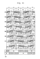
- FIG. 11 is a signal timing diagram for explaining an exemplary embodiment of a method of displaying the 3D image using the display apparatus of FIG. 10 ;
- FIG. 12 is a signal timing for explaining an exemplary embodiment of a method of displaying a 3D image using another alternative exemplary embodiment of a display apparatus
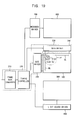
- FIG. 13 is a block diagram illustrating an exemplary embodiment of a timing controller of a display apparatus
- FIG. 14 is a block diagram illustrating an exemplary embodiment of a data driver of the display apparatus of FIG. 13 ;
- FIG. 15 is a conceptual diagram for explaining an exemplary embodiment of a method of displaying a 3D image using another alternative exemplary embodiment of a display apparatus
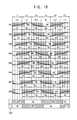
- FIG. 16 is a signal timing diagram for explaining an exemplary embodiment of a method of displaying the 3D image using the display apparatus of FIG. 15 ;
- FIG. 17 is a conceptual diagram for explaining an exemplary embodiment of a method of displaying a 3D image using another alternative exemplary embodiment of a display apparatus
- FIG. 18 is a signal timing diagram for explaining an exemplary embodiment of a method of displaying the 3D image using the display apparatus of FIG. 17 ;
- FIG. 19 is a block diagram illustrating an alternative exemplary embodiment of a display apparatus according to the invention.
- first, second, etc. may be used herein to describe various elements, components, regions, layers and/or sections, these elements, components, regions, layers and/or sections should not be limited by these terms. These terms are only used to distinguish one element, component, region, layer or section from another region, layer or section. Thus, a first element, component, region, layer or section discussed below could be termed a second element, component, region, layer or section without departing from the teachings of the invention.
- spatially relative terms such as “beneath”, “below”, “lower”, “above”, “upper” and the like, may be used herein for ease of description to describe one element or feature's relationship to another element(s) or feature(s) as illustrated in the figures. It will be understood that the spatially relative terms are intended to encompass different orientations of the device in use or operation in addition to the orientation depicted in the figures. For example, if the device in the figures is turned over, elements described as “below” or “beneath” other elements or features would then be oriented “above” the other elements or features. Thus, the exemplary term “below” can encompass both an orientation of above and below. The device may be otherwise oriented (rotated 90 degrees or at other orientations) and the spatially relative descriptors used herein interpreted accordingly.
- Exemplary embodiments are described herein with reference to cross section illustrations that are schematic illustrations of idealized embodiments. As such, variations from the shapes of the illustrations as a result, for example, of manufacturing techniques and/or tolerances, are to be expected. Thus, embodiments described herein should not be construed as limited to the particular shapes of regions as illustrated herein but are to include deviations in shapes that result, for example, from manufacturing. For example, a region illustrated or described as flat may, typically, have rough and/or nonlinear features. Moreover, sharp angles that are illustrated may be rounded. Thus, the regions illustrated in the figures are schematic in nature and their shapes are not intended to illustrate the precise shape of a region and are not intended to limit the scope of the claims set forth herein.
- FIG. 1 is a block diagram illustrating an exemplary embodiment of a display apparatus according to the invention.
- the display apparatus includes a display panel 100, a panel driving part 200, a light source part 300, a light source driver 400 and light converting glasses 500.
- the display panel 100 includes a plurality of pixels P which displays an image.
- each of the pixels includes a switching element TR electrically connected to a gate line GL and a data line DL, a liquid crystal capacitor CLC connected to the switching element TR and a storage capacitor CST connected to the switching element TR.
- the pixels P may be disposed substantially in a matrix form.
- the display panel 100 may include two substrates opposite to each other and a liquid crystal layer disposed between the two substrates.
- the display panel 100 may be divided into a plurality of display blocks.
- the display panel 100 may be divided into eight display blocks.
- each of the display blocks may include a plurality of pixels. Longer sides of the display blocks may extend in a direction substantially parallel to the gate line GL. Shorter sides of the display blocks may extend in a direction substantially parallel to the data line DL. The display blocks adjacent to each other may be disposed in the direction substantially parallel to the data line DL.
- the display panel 100 is divided into eight display blocks as described above, but the invention is not limited thereto.
- the panel driving part 200 includes a frame rate converter 210, a timing controller 220, a gate driver 230 and a data driver 240.
- the frame rate converter 210 receives input image data RGB (shown in FIG. 5 ) from an external apparatus (not shown).
- the input image data RGB may include red image data R, green image data G and blue image data B.
- the frame rate converter 210 converts a frame rate of the input image data RGB to generate first image data FRGB (shown in FIG. 5 ).
- the first image data FRGB may have a frame rate twice the frame rate of the input image data RGB.
- the input image data RGB has the frame rate of about 120 hertz (Hz)
- the first image data FRGB has the frame rate of about 240 Hz.
- the first image data FRGB when the input image data RGB includes a left image and a right image, the first image data FRGB includes two left images and two right images.
- the frame rate converter 210 may copy the left image and the right image. In an exemplary embodiment, the frame rate converter 210 may operate a motion compensation of the left and right images.
- the frame rate converter 210 outputs the first image data FRGB to the timing controller 220.
- the timing controller 220 receives an input control signal from outside. In an alternative exemplary embodiment, the timing controller 220 may receive the input control signal from the frame rate converter 210.
- the input control signal may include a master clock signal, a data enable signal, a vertical synchronizing signal and a horizontal synchronizing signal, for example.
- the timing controller 220 generates a first control signal for controlling a driving timing of the gate driver 230, a second control signal for controlling a driving timing of the data driver 240 and a third control signal for controlling a driving timing of the light source driver 400.
- the timing controller 220 outputs the first control signal to the gate driver 230.
- the timing controller 220 outputs the second control signal to the data driver 240.
- the timing controller 220 outputs the third control signal to the light source driver 400.
- the first control signal may include a vertical start signal and a gate clock signal.
- the second control signal may include a horizontal start signal, a load signal and a polarity inverting signal.
- the timing controller 220 receives the first image data FRGB from the frame rate converter 210.
- the timing controller 220 converts the first image data FRGB to generate converted image data.
- the timing controller 220 outputs the converted image data to the data driver 240.
- the timing controller 220 may control an operation of the light converting glasses 500 based on an image displayed on the display panel 100.
- Timing controller 220 An image processing of the timing controller 220 will be described later in detail referring to FIG. 5 .
- the gate driver 230 receives the first control signal from the timing controller 220.
- the gate driver 230 generates a gate signal for driving the gate line GL in response to the first control signal.
- the gate driver 230 outputs the gate signal to the gate line GL.
- the data driver 240 receives the second control signal and the converted image data from the timing controller 220.
- the data driver 240 converts the converted image data into a data voltage in an analog form in response to the second control signal.
- the data driver 240 outputs the data voltage to the data line DL.
- the light source part 300 provides light to the display panel 100.
- the light source part 300 may be a backlight assembly disposed under the display panel 100.
- the light source part 300 may be a direct type backlight assembly including a plurality of light sources disposed under the display panel 100.
- the light source part 300 may be an edge type backlight assembly including a plurality of light sources corresponding to an edge portion of the display panel 100 and a light guide plate.
- the light source part 300 may be divided into a plurality of light emitting blocks.
- the light source part 300 may be divided into eight light emitting blocks.
- Each of the light emitting blocks may include one or more light sources. Longer sides of the light emitting blocks may extend in the direction substantially parallel to the gate line GL. Shorter sides of the light emitting blocks may extend in the direction substantially parallel to the data line DL.
- the light emitting blocks adjacent to each other may be disposed in the direction substantially parallel to the data line DL.
- the light source part 300 is divided into eight light emitting blocks, but the invention is not limited thereto.
- the light emitting blocks may sequentially provide light to the display blocks along a scanning direction of the display blocks.
- the scanning direction of the display blocks may be substantially parallel to the data line DL.
- the light emitting blocks may correspond to the display blocks, respectively.
- a first light emitting block provides the light to a first display block.
- a second light emitting block provides the light to a second display block.
- the light source part 300 is divided into a plurality of light emitting blocks, but the invention is not limited thereto.
- the light source part 300 may be driven in a blinking type, in which all of the light sources of the light source part 300 are simultaneously turned on and off.
- the light source part 300 may be continuously turned on.
- the light source driver 400 receives the third control signal from the timing controller 220.
- the light source driver 400 drives the light source part 300 in response to the third control signal.
- the light source driver 400 may be connected to the panel driver 200.
- the light source driver 400 may control the light source part 300 such that the light emitting blocks are sequentially turned on along the scanning direction of the display blocks. Turned-on durations of the adjacent light emitting blocks may overlap each other.
- the light converting glasses 500 includes a left glass 510 and a right glass 520.
- the light converting glasses 500 may be shutter glasses which selectively open and close the left glass 510 and the right glass 520 to convert a two-dimensional ("2D") image into a three-dimensional (“3D”) image.
- the light converting glasses 500 may selectively open and close the left glass 510 and the right glass 520 in response to a shutter control signal received from the timing control signal 220.
- the light converting glasses 500 functions as a light converting element, which selectively or totally blocks light, to convert the 2D image into the 3D image.
- a retarder (not shown) unit may be disposed on the display panel 100 as the light converting element.
- the retarder unit may include one of a patterned retarder and an active retarder.
- the retarder unit may selectively transmit polarized light of the image displayed in the pixel.
- the polarized light may be selectively transmitted by a second light converting element.
- the second light converting element may be polarizing glasses.
- the retarder unit may polarize a left image or a right image by the timing controller, the left glass 510 may transmit the polarized left image, and the right glass 520 may transmit the polarized right image.
- the retarder unit may be an active retarder unit which changes a polarizing characteristic according to a frame of the image displayed on the display panel 100.
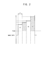
- FIG. 2 is a timing diagram illustrating an exemplary embodiment of image data applied to the display panel 100 of FIG. 1 .
- FIG. 3 is a conceptual diagram for explaining an exemplary embodiment of a method of displaying the 3D image using the display apparatus of FIG. 1 .
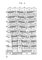
- FIG. 4 is a signal timing diagram for explaining an exemplary embodiment of a method of displaying the 3D image using the display apparatus of FIG. 1 .
- the display panel 100, the light source part 300 and the light converting glasses 500 may be synchronized with one another.
- a left image L and a right image R are applied to a pixel of the display panel 100 during a normal data application period.
- Converted images LC and RC are applied to the pixel of the display panel 100 during a converted data application period, which is prior to the normal data application period.
- the converted images LC and RC have grayscale values less than grayscale values of the left and right images L and R.
- the display panel 100 sequentially displays the converted left image LC, the left image L, the converted right image RC and the right image R.
- Vcom denotes a common voltage, which is applied to a common electrode of the display panel.
- the converted left image LC is generated based on the left image L.
- the converted left image LC has a grayscale value less than a grayscale value of the left image L.
- the left image L has a grayscale value corresponding to an image to be viewed at a left eye of a viewer.
- the converted right image RC is generated based on the right image R.
- the converted right image RC has a grayscale value less than a grayscale value of the right image R.
- the right image R has a grayscale value corresponding to an image to be viewed at a right eye of the viewer.
- Each of the converted left image LC, the left image L, the converted right image RC and the right image R is displayed on the pixel of the display panel 100 corresponding to a frame 1F.
- the light source part 300 includes the light emitting blocks.
- the light emitting blocks are sequentially turned on along the scanning direction of the display panel 100.
- the light emitting blocks sequentially provide light to the display blocks of the display panel 100.
- the display panel 100 includes eight display blocks, e.g., a first to eight display blocks DB1 to DB8, and the light source part 300 includes eight light emitting blocks, but not being limited thereto.
- Open and close times of the light converting glasses 500 are adjusted corresponding to the left image L and the right image R.
- FIG. 4 shows an image voltage of a pixel in each of the display blocks DB1 to DB8 based on a response time of a liquid crystal layer.
- first and second left images L1 and L2 have relatively high grayscale values
- the right image R1 has a relatively low grayscale value.
- first frame F1 voltages corresponding to a first converted left image LC1 are sequentially applied to the first to eight display blocks DB1 to DB8 along the scanning direction.
- the first converted left image LC1 is generated based on the first left image L1 to have a grayscale value less than a grayscale value of the first left image L1.
- voltages corresponding to the first left image L1 are sequentially applied to the first to eight display blocks DB1 to DB8 along the scanning direction.
- a third frame F3 voltages corresponding to a first converted right image RC1 are sequentially applied to the first to eight display blocks DB1 to DB8 along the scanning direction.
- the first converted right image RC1 is generated based on the first right image R1 to have a grayscale value less than a grayscale value of the first right image R1.
- voltages corresponding to the first right image R1 are sequentially applied to the first to eight display blocks DB1 to DB8 along the scanning direction.
- a fifth frame F5 voltages corresponding to a second converted left image LC2 are sequentially applied to the first to eight display blocks DB1 to DB8 along the scanning direction.
- the second converted left image LC2 is generated based on the second left image L2 to have a grayscale value less than a grayscale value of the second left image L2.
- voltages corresponding to the second left image L2 are sequentially applied to the first to eight display blocks DB1 to DB8 along the scanning direction.
- a voltage corresponding to the first converted left image LC1 is applied to the first pixel such that the first pixel displays the first converted left image LC1.
- a voltage corresponding to the first left image L1 is applied to the first pixel such that the first pixel displays the first left image L1.
- a voltage corresponding to the first converted right image RC1 is applied to the first pixel such that the first pixel displays the first converted right image RC1.
- a voltage corresponding to the first right image R1 is applied to the first pixel such that the first pixel displays the first right image R1.
- a voltage corresponding to the second converted left image LC2 is applied to the first pixel such that the first pixel displays the second converted left image LC2.
- a voltage corresponding to the second left image L2 is applied to the first pixel such that the first pixel displays the second left image L2.
- the second display block DB2 has a driving timing delayed with respect to a driving timing of the first display block DB1.
- a voltage corresponding to the first converted left image LC1 is applied to the second pixel such that the second pixel displays the first converted left image LC1.
- a voltage corresponding to the first left image L1 is applied to the second pixel such that the second pixel displays the first left image L1.
- a voltage corresponding to the first converted right image RC1 is applied to the second pixel such that the second pixel displays the first converted right image RC1.
- a voltage corresponding to the first right image R1 is applied to the second pixel such that the second pixel displays the first right image R1.
- a voltage corresponding to the second converted left image LC2 is applied to the second pixel such that the second pixel displays the second converted left image LC2.
- a voltage corresponding to the second left image L2 is applied to the second pixel such that the second pixel displays the second left image L2.
- the third to eighth display blocks DB3 to DB8 are sequentially driven.
- the light source part 300 provides light to the first to eighth display blocks DB1 to DB8 synchronized with the scanning driving of the first to eighth display blocks DB1 to DB8.
- the light source part 300 temporally provides light to the pixels in the second period P2 and the fourth period P4.
- the light source part 300 temporally provides light to the pixels when the pixels display the left and right images L and R to be viewed at the left and right eyes of the viewer.
- Open and close times of the light converting glasses 500 are adjusted corresponding to the left image L and the right image R.
- the left glass 510 is turned off during the first frame F1, the fourth frame F4 and the fifth frame F5.
- the left glass 510 is turned on during the second frame F2, the third frame F3 and the sixth frame F6.
- the right glass 520 is turned on during the first frame F1, the fourth frame F4 and the fifth frame F5.
- the right glass 520 is turned off during the second frame F2, the third frame F3 and the sixth frame F6.
- the first converted left image LC1 is applied to the pixel prior to applying the first left image L1, which is the image to be viewed at the left eye of the viewer, such that the first converted left image LC1 pretilts the liquid crystal layer corresponding to the pixel.
- the pixel may rapidly display the first left image L1 to be viewed at the left eye of the viewer such that a luminance of the display panel 100 increases.
- the first converted right image RC1 having a grayscale value less than the grayscale value of the first right image R1, which is the image to be viewed at right left eye of the viewer, is applied to the pixel.
- the pixel may rapidly display the first right image R1 to be viewed at the right eye of the viewer such that a crosstalk of the 3D image is effectively prevented.
- the second converted left image LC2 having a grayscale value less than a grayscale value of the second left image L2, which is an image to be viewed at the left eye of the viewer, is applied to the pixel.
- a crosstalk of the 3D image due to leakage light between the light emitting blocks is effectively prevented.
- FIG. 5 is a block diagram illustrating an exemplary embodiment of the timing controller 220 of FIG. 1 .
- the timing controller 220 may include an adaptive color correction ("ACC") part 222, a dynamic capacitance compensation (“DCC”) part 224 and a grayscale converting part 226.
- ACC adaptive color correction
- DCC dynamic capacitance compensation
- the ACC part 222 operates adaptive color correction to the first image data FRGB.
- the ACC part 222 compensates the first image data FRGB using a gamma curve.
- the DCC part 224 operates dynamic capacitance compensation, which compensates a grayscale data of a current frame data using a previous frame data and the current frame data.
- the first image data FRGB includes two duplicated left images and two duplicated right images such that the DCC part 224 may operate the dynamic capacitance compensation in each two frames.
- a grayscale value of the left image L may be generated by comparing an input left image of the current frame to an input right image or an input left image of the previous frame.
- a grayscale value of the right image R may be generated by comparing an input right image of the current frame to an input left image or an input right image of the previous frame.
- the grayscale value of the second left image L2 may be generated by comparing a grayscale value of a second input left image corresponding to the second left image L2 to a grayscale value of a first input right image corresponding to the first right image R1.
- the grayscale value of the second right image R2 may be generated by comparing a grayscale value of a second input right image corresponding to the second right image R2 to a grayscale value of a second input left image corresponding to the second left image L2.
- a position of the ACC part 222 and the DCC part 224 may be switched to each other. Accordingly, in such an embodiment, an operation sequence of the ACC and the DCC may be switched to each other.
- the grayscale converting part 226 generates the converted left image LC having a grayscale value less than the grayscale value of the left image L based on the left image L.
- the grayscale converting part 226 generates the converted right image RC having a grayscale value less than the grayscale value of the right image R based on the right image R.
- the converted left image LC and the converted right image RC may have grayscale values substantially the same as the grayscale values of the left image L and the right image R.
- the converted left image LC and the converted right image RC may have the grayscale values substantially the same as each other.
- the grayscale converting part 226 may generate the converted left and right images LC and RC by multiplying the grayscale values of the left and right images L and R by a converting value.
- the converting value is less than one.
- the left image L has the grayscale value of 256 and the converting value is 0.75 such that the converted left image LC may have the grayscale value of 192.
- the grayscale converting part 226 may include a multiplexer circuit to multiply the grayscale values of the left and right images L and R by the converting value.
- the converting value may be determined based on the grayscale values of the left and right images L and R. In an exemplary embodiment, the converting value may be controlled by a user.
- the grayscale converting part 226 may generate the converted left and right images LC and RC using a lookup table including the grayscale values corresponding to the grayscale values of the left and right images L and R.
- the timing controller 200 may further include a memory (not shown) that stores the lookup table.
- the grayscale converting part 226 outputs the converted left image LC, the left image L, the converted right image RC and the right image R to the data driver 240.
- FIG. 6 is a block diagram illustrating an exemplary embodiment of the data driver 240 of FIG. 1 .
- the data driver 240 includes a shift register 242, a latch 244, a signal processor 246 and a buffer 248.
- the shift register 242 outputs a latch pulse to the latch 244.
- the latch 244 temporally stores the converted left image LC, the left image L, the converted right image RC and the right image R, and outputs the converted left image LC, the left image L, the converted right image RC and the right image R to the signal processor 246.
- the signal processor 246 converts the converted left image LC, the left image L, the converted right image RC and the right image R in a digital form to data voltages in an analog form based on the gamma reference voltages, and outputs the data voltages to the buffer 248.
- the buffer 248 compensates the data voltages to have uniform levels, and outputs the data voltages to the data lines DL.
- a luminance of the display panel 100 substantially increases, and a crosstalk of the 3D image is effectively prevented such that display quality of the 3D image is improved.
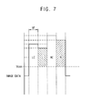
- FIG. 7 is a timing diagram illustrating image data applied to a display panel of an alternative exemplary embodiment of a display apparatus according to the invention.
- FIG. 8 is a conceptual diagram for explaining an exemplary embodiment of a method of displaying a 3D image using the display apparatus of FIG. 7 .
- FIG. 9 is a signal timing diagram for explaining an exemplary embodiment of a method of displaying the 3D image using the display apparatus of FIG. 7 .
- a display apparatus and a method of displaying the 3D image of FIG. 9 is substantially the same as the display apparatus and the method of displaying the 3D image of FIGS. 1 to 6 except for the converted left image LC and the converted right image RC.
- the same reference characters will be used to refer to the same or like elements as those described in the exemplary embodiment of FIGS. 1 to 6 , and any repetitive detailed description thereof will be omitted or simplified.
- the display apparatus includes a display panel 100, a panel driver 200, a light source part 300, a light source driver 400 and light converting glasses 500.
- the display panel 100, the light source part 300 and the light converting glasses 500 may be synchronized with one another.
- a left image L and a right image R are applied to a pixel of the display panel 100 during a normal data application period.
- Converted images LC and RC are applied to the pixel of the display panel 100 during a converted data application period, which is prior to the normal data application period.
- the converted images LC and RC have grayscale values greater than grayscale values of the left and right images L and R.
- the display panel 100 sequentially displays the converted left image LC, the left image L, the converted right image RC and the right image R.
- Vcom denotes a common voltage, which is applied to a common electrode of the display panel.
- the converted left image LC is generated based on the left image L.
- the converted left image LC has a grayscale value greater than a grayscale value of the left image L.
- the left image L has a grayscale value corresponding to the image to be viewed at a left eye of a viewer.
- the converted right image RC is generated based on the right image R.
- the converted right image RC has a grayscale value greater than a grayscale value of the right image R.
- the right image R has a grayscale corresponding to the image to be viewed at a right eye of the viewer.
- Each of the converted left image LC, the left image L, the converted right image RC and the right image R is displayed on the pixel of the display panel 100 corresponding to a frame IF.
- the light source part 300 includes the light emitting blocks.
- the light emitting blocks are sequentially turned on along the scanning direction of the display panel 100.
- the light emitting blocks sequentially provide light to the display blocks of the display panel 100.
- the display panel 100 includes eight display blocks, e.g., the first to eighth display blocks DB1 to DB8, and the light source part 300 includes eight light emitting blocks.
- Open and close times of the light converting glasses 500 are adjusted corresponding to the left image L and the right image R.
- a voltage corresponding to the first converted left image LC1 is applied to the first pixel such that the first pixel displays the first converted left image LC1.
- a voltage corresponding to the first left image L1 is applied to the first pixel such that the first pixel displays the first left image L1.
- a voltage corresponding to the first converted right image RC1 is applied to the first pixel such that the first pixel displays the first converted right image RC1.
- a voltage corresponding to the first right image R1 is applied to the first pixel such that the first pixel displays the first right image R1.
- a voltage corresponding to the second converted left image LC2 is applied to the first pixel such that the first pixel displays the second converted left image LC2.
- a voltage corresponding to the second left image L2 is applied to the first pixel such that the first pixel displays the second left image L2.
- the second display block DB2 has a driving timing delayed with respect to a driving timing of the first display block DB1.
- the third to eighth display blocks DB3 to DB8 are sequentially driven.
- the first converted left image LC1 is applied to the pixel prior to applying the first left image L1 which is the image to be viewed at the left eye of the viewer such that the pixel is driven in an overshoot driving method.
- the pixel may rapidly display the first left image L1 to be viewed at the left eye of the viewer. Therefore, in such an embodiment, a luminance of the display panel 100 increases.
- the grayscale converting part 226 of the timing controller 220 generates the converted left image LC having a grayscale value greater than the grayscale value of the left image L based on the left image L.
- the grayscale converting part 226 generates the converted right image RC having a grayscale value greater than the grayscale value of the right image R based on the right image R.
- the grayscale converting part 226 may generate the converted left and right images LC and RC by multiplying the grayscale values of the left and right images L and R by a converting value.
- the converting value is greater than one.
- the converting value may be determined based on the grayscale values of the left and right images L and R.
- the converting value may be varied by a user.
- the grayscale converting part 226 may generate the converted left and right images LC and RC using a lookup table including the grayscale values corresponding to the grayscale values of the left and right images L and R.
- a response time of the liquid crystal layer increases such that a luminance of the display panel 100 increases and luminance uniformity is improved.
- display quality of the 3D image is improved.
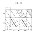
- FIG. 10 is a conceptual diagram for explaining an exemplary embodiment of a method of displaying a 3D image using another alternative exemplary embodiment of a display apparatus.
- FIG. 11 is a signal timing diagram for explaining an exemplary embodiment of a method of displaying the 3D image using the display apparatus of FIG. 10 .
- a display apparatus and a method of displaying the 3D image of FIGS. 10 and 11 is substantially the same as the display apparatus and the method of displaying the 3D image shown in FIGS. 1 to 6 except for a sequence of displaying the images LC, L, RC and R.
- the same reference characters will be used to refer to the same or like elements as those described in the exemplary embodiment of FIGS. 1 to 6 , and any repetitive detailed description thereof will be omitted or simplified.
- the display apparatus includes a display panel 100, a panel driver 200, a light source part 300, a light source driver 400 and light converting glasses 500.
- the display panel 100, the light source part 300 and the light converting glasses 500 may be synchronized with one another.
- the display panel 100 sequentially displays the left image L, the converted left image LC, the right image R and the converted right image RC.
- the converted left image LC is generated based on the left image L.
- the converted left image LC has a grayscale value less than a grayscale value of the left image L.
- the left image L has a grayscale corresponding to an image to be viewed at a left eye of a viewer.
- the converted right image RC is generated based on the right image R.
- the converted right image RC has a grayscale value less than a grayscale value of the right image R.
- the right image R has a grayscale value corresponding to an image to be viewed at a right eye of the viewer.
- Each of the left image L, the converted left image LC, the right image R and the converted right image RC is displayed on the pixel of the display panel 100 corresponding to a frame IF.
- the light source part 300 includes the light emitting blocks.
- the light emitting blocks are sequentially turned on along the scanning direction of the display panel 100.
- the light emitting blocks sequentially provide light to the display blocks of the display panel 100.
- the display panel 100 includes eight display blocks, e.g., the first to eight display blocks DB1 to DB8, and the light source part 300 includes eight light emitting blocks.
- Open and close times of the light converting glasses 500 are adjusted corresponding to the left image L and the right image R.
- a voltage corresponding to the first left image L1 is applied to the first pixel such that the first pixel displays the first left image L1.
- a voltage corresponding to the first converted left image LC1 is applied to the first pixel such that the first pixel displays the first converted left image LC1.
- a voltage corresponding to the first right image R1 is applied to the first pixel such that the first pixel displays the first right image R1.
- a voltage corresponding to the first converted right image RC1 is applied to the first pixel such that the first pixel displays the first converted right image RC1.
- a voltage corresponding to the second left image L2 is applied to the first pixel such that the first pixel displays the second left image L2.
- a voltage corresponding to the second converted left image LC2 is applied to the first pixel such that the first pixel displays the second converted left image LC2.
- the second display block DB2 has a driving timing delayed with respect to a driving timing of the first display block DB1.
- the third to eighth display blocks DB3 to DB8 are sequentially driven.
- the light source part 300 temporally provides light to the pixels in an ending portion of the first period P1 and a beginning portion of the second period P2.
- the light source part 300 temporally provides light to the pixels in an ending portion of the third period P3 and a beginning portion of the fourth period P4.
- the first converted left image LC1 having the grayscale value less than the grayscales value of the first left image L1 is displayed such that a crosstalk decreases.
- a luminance of the display panel 100 increases when compared to a conventional display panel that displays a black image during the second period P2,.
- a crosstalk of the 3D image decreases and a luminance of the display panel 100 increases such that display quality of the 3D image is improved.
- FIG. 12 is a conceptual diagram for explaining an exemplary embodiment of a method of displaying a 3D image using another alternative exemplary embodiment of a display apparatus.
- a display apparatus and a method of displaying the 3D image of FIG. 12 is substantially the same as the display apparatus and the method of displaying the 3D image shown in FIGS. 1 to 6 except that the light source part 300 is continuously turned on.
- the same reference characters will be used to refer to the same or like elements as those described in the exemplary embodiment of FIGS. 1 to 6 , and any repetitive detailed description thereof will be omitted or simplified.
- the display apparatus includes a display panel 100, a panel driver 200, a light source part 300, a light source driver 400 and light converting glasses 500.
- the display panel 100 and the light converting glasses 500 may be synchronized with each other.
- the display panel 100 sequentially displays the converted left image LC, the left image L, the converted right image RC and the right image R.
- the converted left image LC is generated based on the left image L.
- the converted left image LC has a grayscale value less than a grayscale value of the left image L.
- the left image L has a grayscale value corresponding to an image to be viewed at a left eye of a viewer.
- the converted right image RC is generated based on the right image R.
- the converted right image RC has a grayscale value less than a grayscale value of the right image R.
- the right image R has a grayscale value corresponding to an image to be viewed at a right eye of the viewer.
- Each of the converted left image LC, the left image L, the converted right image RC and the right image R is displayed on the pixel of the display panel 100 corresponding to a frame 1F.
- the light source part 300 continuously provides light to the display panel 100.
- Open and close times of the light converting glasses 500 are adjusted corresponding to the left image L and the right image R. Both of a left glass 510 and a right glass 520 of the light converting glasses 500 may be turned off corresponding to a scanning time of the display panel 100. The close time of the left glass 510 partially overlap the close time of the right glass 520.
- a luminance of the display panel 100 increases, and a crosstalk of the 3D image is effectively prevented such that display quality of the 3D image is improved.
- FIG. 13 is a block diagram illustrating a timing controller of an alternative exemplary embodiment of a display apparatus.
- FIG. 14 is a block diagram illustrating an exemplary embodiment of a data driver of the display apparatus of FIG. 13 .
- a display apparatus and a method of displaying the 3D image of FIGS. 13 and 14 is substantially the same as the display apparatus and the method of displaying the 3D image of the exemplary embodiment shown in FIGS. 1 to 6 except that the data driver 240 generates the converted left and right images LC and RC.
- the same reference characters will be used to refer to the same or like elements as those described in the exemplary embodiment of FIGS. 1 to 6 , and any repetitive detailed description thereof will be omitted or simplified.
- the display apparatus includes a display panel 100, a panel driver 200, a light source part 300, a light source driver 400 and light converting glasses 500.
- the display panel 100, the light source part 300 and the light converting glasses 500 may be synchronized with one another.
- the display panel 100 sequentially displays the converted left image LC, the left image L, the converted right image RC and the right image R.
- the converted left image LC is generated based on the left image L.
- the converted left image LC has a grayscale value greater than a grayscale value of the left image L.
- the left image L has a grayscale value corresponding to an image to be viewed at a left eye of a viewer.
- the converted right image RC is generated based on the right image R.
- the converted right image RC has a grayscale value greater than a grayscale value of the right image R.
- the right image R has a grayscale value corresponding to an image to be viewed at a right eye of the viewer.
- the panel driver 200 includes a frame rate converter 210, a timing controller 220, a gate driver 230 and a data driver 240.
- the timing controller may include an ACC part 222 and a DCC part 224.
- the ACC part 222 operates adaptive color correction to the first image data FRGB.
- the DCC part 224 operates dynamic capacitance compensation, which compensates a grayscale data of the current frame data using the previous frame data and the current frame data.
- the timing controller 220 outputs two duplicated left images L and L and two duplicated right images R and R to the data driver 240.
- the data driver 240 includes a grayscale converting part 241, a shift register 242, a latch 244, a signal processor 246 and a buffer 248.
- the grayscale converting part 241 generates the converted left image LC having a grayscale value less than a grayscale value of the left image L based on the left image L.
- the grayscale converting part 241 generates the converted right image RC having a grayscale value less than the right image R based on the right image R.
- the grayscale converting part 241 may generate the converted left and right images LC and RC by multiplying the grayscale values of the left and right images L and R by a converting value.
- the converting value is less than one.
- the converting value may be determined based on the grayscale values of the left and right images L and R.
- the grayscale converting part 241 may generate the converted left and right images LC and RC using a lookup table including the grayscale values corresponding to the grayscale values of the left and right images L and R.
- the grayscale converting part 241 outputs the converted left image LC, the left image L, the converted right image RC and the right image R to the latch 244.
- the shift register 242 outputs a latch pulse to the latch 244.
- the latch 244 temporally stores the converted left image LC, the left image L, the converted right image RC and the right image R and outputs the converted left image LC, the left image L, the converted right image RC and the right image R to the signal processor 246.
- the signal processor 246 converts the converted left image LC, the left image L, the converted right image RC and the right image R in a digital form to data voltages in an analog form based on the gamma reference voltages and outputs the data voltages to the buffer 248.
- the buffer 248 compensates the data voltages to have uniform levels and outputs the data voltages to the data lines DL.
- a luminance of the display panel 100 increases, and a crosstalk of the 3D image is effectively prevented such that display quality of the 3D image is improved.
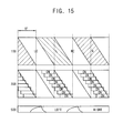
- FIG. 15 is a conceptual diagram for explaining an exemplary embodiment of a method of displaying a 3D image using another alternative exemplary embodiment of a display apparatus.
- FIG. 16 is a signal timing diagram for explaining an exemplary embodiment of a method of displaying the 3D image using the display apparatus of FIG. 15 .
- a display apparatus and a method of displaying the 3D image of FIGS. 14 and 15 is substantially the same as the display apparatus and the method of displaying the 3D image shown in FIGS. 1 to 6 except for a driving method of the light converting glasses 500.
- the same reference characters will be used to refer to the same or like elements as those described in the exemplary embodiment of FIGS. 1 to 6 , and any repetitive detailed description thereof will be omitted or simplified.
- the display apparatus includes a display panel 100, a panel driver 200, a light source part 300, a light source driver 400 and light converting glasses 500.
- the display panel 100, the light source part 300 and the light converting glasses 500 may be synchronized with one another.
- the display panel 100 sequentially displays the converted left image LC, the left image L, the converted right image RC and the right image R.
- the converted left image LC is generated based on the left image L.
- the converted left image LC has a grayscale value less than a grayscale value of the left image L.
- the left image L has a grayscale value corresponding to an image to be viewed at a left eye of a viewer.
- the converted right image RC is generated based on the right image R.
- the converted right image RC has a grayscale value less than a grayscale value of the right image R.
- the right image R has a grayscale value corresponding to an image to be viewed at a right eye of the viewer.
- Each of the converted left image LC, the left image L, the converted right image RC and the right image R is displayed on the pixel of the display panel 100 corresponding to a frame IF.
- the light source part 300 includes the light emitting blocks.
- the light emitting blocks are sequentially turned on along the scanning direction of the display panel 100.
- the light emitting blocks sequentially provide light to the display blocks of the display panel 100.
- the display panel 100 includes eight display blocks, e.g., the first to eighth display blocks DB1 to DB8, and the light source part 300 includes eight light emitting blocks.
- Open and close times of the light converting glasses 500 are adjusted corresponding to the left image L and the right image R. Both of a left glass 510 and a right glass 520 of the light converting glasses 500 may be turned on in a specific time point. The open time of the left glass 510 partially overlap the open time of the right glass 520.
- the left glass 510 is turned on during a second frame F2, a third frame F3 and a beginning portion of a fourth frame F4 and a sixth frame F6.
- the right glass 520 is turned on during a first frame F1, a beginning portion of the second frame F2, the fourth frame F4, a fifth frame F5 and a beginning portion of the sixth frame F6.
- both of the left and right glasses 510 and 520 are turned on the beginning portion of the second frame F2, the beginning portion of the fourth frame F4 and the beginning portion of the sixth frame F6.
- a luminance of the display panel 100 increases, and a crosstalk of the 3D image is effectively prevented such that display quality of the 3D image is improved.
- FIG. 17 is a conceptual diagram for explaining an exemplary embodiment of a method of displaying a 3D image using another alternative exemplary embodiment of a display apparatus.
- FIG. 18 is a signal timing diagram for explaining an exemplary embodiment of a method of displaying the 3D image using the display apparatus of FIG. 17 .
- a display apparatus and a method of displaying the 3D image of FIG. 17 is substantially the same as the display apparatus and the method of displaying the 3D image of the exemplary embodiment explained referring to FIGS. 1 to 6 except for a driving method of the light converting glasses 500.
- the same reference characters will be used to refer to the same or like elements as those described in the exemplary embodiment of FIGS. 1 to 6 , and any repetitive detailed description thereof will be omitted or simplified.
- the display apparatus includes a display panel 100, a panel driver 200, a light source part 300, a light source driver 400 and light converting glasses 500.
- the display panel 100, the light source part 300 and the light converting glasses 500 may be synchronized with one another.
- the display panel 100 sequentially displays the converted left image LC, the left image L, the converted right image RC and the right image R.
- the converted left image LC is generated based on the left image L.
- the converted left image LC has a grayscale value less than a grayscale value of the left image L.
- the left image L has a grayscale value corresponding to an image to be viewed at a left eye of a viewer.
- the converted right image RC is generated based on the right image R.
- the converted right image RC has a grayscale value less than a grayscale value of the right image R.
- the right image R has a grayscale value corresponding to an image to be viewed at a right eye of the viewer.
- Each of the converted left image LC, the left image L, the converted right image RC and the right image R is displayed on the pixel of the display panel 100 corresponding to a frame IF.
- the light source part 300 includes the light emitting blocks.
- the light emitting blocks are sequentially turned on along the scanning direction of the display panel 100.
- the light emitting blocks sequentially provide light to the display blocks of the display panel 100.
- the display panel 100 includes eight display blocks, e.g., the first to eighth display blocks DB1 to DB8, and the light source part 300 includes eight light emitting blocks.
- Open and close times of the light converting glasses 500 are adjusted corresponding to the left image L and the right image R. Both of a left glass 510 and a right glass 520 of the light converting glasses 500 may be turned off in a specific time point. The close time of the left glass 510 partially overlap the close time of the right glass 520.
- the left glass 510 is turned off during a first frame F1, a beginning portion of a second frame F2, a fourth frame F4, a fifth frame F5 and beginning portion of a sixth frame F6.
- the right glass 520 is turned off during the second frame F2, a third frame F3, a beginning portion of the fourth frame F4, the sixth frame F6.
- both of the left and right glasses 510 and 520 are turned off the beginning portion of the second frame F2, the beginning portion of the fourth frame F4 and the beginning portion of the sixth frame F6.
- a luminance of the display panel 100 increases and a crosstalk of the 3D image is effectively prevented such that display quality of the 3D image is improved.
- FIG. 19 is a block diagram illustrating an alternative exemplary embodiment of a display apparatus according to the invention.
- a display apparatus and a method of displaying the 3D image of FIG. 19 is substantially the same as the display apparatus and the method of displaying the 3D image shown in FIGS. 1 to 6 except that the display apparatus includes a retarder unit 600 as a light converting element.
- the same reference characters will be used to refer to the same or like elements as those described in the exemplary embodiment of FIGS. 1 to 6 , and any repetitive detailed description thereof will be omitted or simplified.
- the display apparatus includes a display panel 100, a panel driver 200, a light source part 300, a light source driver 400, a retarder unit 600 and a retarder driver 700.
- the display panel 100 includes a plurality of pixels P which displays an image.
- the panel driving part 200 includes a frame rate converter 210, a timing controller 220, a gate driver 230 and a data driver 240.
- the frame rate converter 210 receives input image data RGB from an external apparatus (not shown).
- the frame rate converter 210 converts a frame rate of the input image data RGB to generate first image data FRGB.
- the frame rate converter 210 outputs the first image data FRGB to the timing controller 220.
- the timing controller 220 receives an input control signal from outside. In an alternative exemplary embodiment, the timing controller 220 may receive the input control signal from the frame rate converter 210.
- the timing controller 220 generates a first control signal for controlling a driving timing of the gate driver 230, a second control signal for controlling a driving timing of the data driver 240 and a third control signal for controlling a driving timing of the light source driver 400.
- the timing controller 220 outputs the first control signal to the gate driver 230.
- the timing controller 220 outputs the second control signal to the data driver 240.
- the timing controller 220 outputs the third control signal to the light source driver 400.
- the timing controller 220 generates a retarder control signal for controlling the retarder unit 600 based on an image to be displayed on the display panel 100.
- the timing controller 220 outputs the retarder control signal to the retarder driver 700.
- the retarder unit is disposed on the display panel 100.
- the retarder unit selectively blocks the images on the display panel 100 such that the retarder unit converts a 2D image into a 3D image.
- the retarder unit 600 may selectively blocks the images on the display panel 100 in response to the retarder control signal.
- the display panel 100, the light source part 300 and the retarder unit 600 may be synchronized with one another.
- the display panel 100 sequentially displays the converted left image LC, the left image L, the converted right image RC and the right image R.
- the converted left image LC is generated based on the left image L.
- the converted left image LC has a grayscale value less than a grayscale value of the left image L.
- the left image L has a grayscale value corresponding to an image to be viewed at a left eye of a viewer.
- the converted right image RC is generated based on the right image R.
- the converted right image RC has a grayscale value less than a grayscale value of the right image R.
- the right image R has a grayscale value corresponding to an image to be viewed at a right eye of the viewer.
- Each of the converted left image LC, the left image L, the converted right image RC and the right image R is displayed on the pixel of the display panel 100 corresponding to a frame IF.
- the light source part 300 includes the light emitting blocks.
- the light emitting blocks are sequentially turned on along the scanning direction of the display panel 100.
- the light emitting blocks sequentially provide light to the display blocks of the display panel 100.
- the display panel 100 includes eight display blocks, e.g., the first to eight display blocks DB1 to DB8, and the light source part 300 includes eight light emitting blocks.
- the display apparatus may further include light converting glasses including a left glass and a right glass.
- the retarder unit 600 may polarize the left image L such that the polarized left image L transmits the left glass when the display panel 100 displays the left image L.
- the retarder unit 600 may polarize the right image R such that the polarized right image R transmits the right glass when the display panel 100 displays the right image R.
- An arrangement of retarders in the retarder unit 600 may be adjusted corresponding to the left image L and the right image R.
- a luminance of the display panel 100 increases and a crosstalk of the 3D image is effectively such that display quality of the 3D image is improved.
- the display panel displays the converted left image and the converted right image such that a crosstalk of the 3D image is effectively prevented and a luminance of the display panel increases such that display quality of the 3D image is improved.
Applications Claiming Priority (1)
| Application Number | Priority Date | Filing Date | Title |
|---|---|---|---|
| KR1020120029036A KR101964892B1 (ko) | 2012-03-21 | 2012-03-21 | 입체 영상 표시 방법 및 이를 수행하는 표시 장치 |
Publications (2)
| Publication Number | Publication Date |
|---|---|
| EP2642761A2 true EP2642761A2 (fr) | 2013-09-25 |
| EP2642761A3 EP2642761A3 (fr) | 2017-01-18 |
Family
ID=47891379
Family Applications (1)
| Application Number | Title | Priority Date | Filing Date |
|---|---|---|---|
| EP13155571.6A Withdrawn EP2642761A3 (fr) | 2012-03-21 | 2013-02-18 | Dispositif et méthode pour afficher des images tri-dimensionnelles |
Country Status (5)
| Country | Link |
|---|---|
| US (2) | US9875696B2 (fr) |
| EP (1) | EP2642761A3 (fr) |
| JP (1) | JP6208444B2 (fr) |
| KR (1) | KR101964892B1 (fr) |
| CN (2) | CN103327350B (fr) |
Families Citing this family (7)
| Publication number | Priority date | Publication date | Assignee | Title |
|---|---|---|---|---|
| CN103439798B (zh) * | 2013-08-30 | 2016-04-06 | 京东方科技集团股份有限公司 | 立体显示装置驱动方法及设备、立体显示装置及立体眼镜 |
| CN103702109B (zh) * | 2013-12-23 | 2016-08-10 | 苏州科技学院 | 一种三维图像灰度查找表测量装置及其方法 |
| CN103731655A (zh) * | 2013-12-30 | 2014-04-16 | 深圳市华星光电技术有限公司 | 快门式三维眼镜的灰度驱动方法 |
| KR102196088B1 (ko) * | 2014-02-21 | 2020-12-30 | 삼성디스플레이 주식회사 | 표시 장치 및 그 구동 방법 |
| WO2015140956A1 (fr) * | 2014-03-19 | 2015-09-24 | 堺ディスプレイプロダクト株式会社 | Dispositif d'affichage et système d'affichage d'image tridimensionnelle |
| CN104735441B (zh) * | 2015-03-30 | 2017-03-08 | 深圳市华星光电技术有限公司 | 显示面板及其显示图像的方法 |
| CN107878202A (zh) * | 2017-11-28 | 2018-04-06 | 黑龙江天有为电子有限责任公司 | 一种具有透明窗口的段码液晶显示仪表 |
Family Cites Families (23)
| Publication number | Priority date | Publication date | Assignee | Title |
|---|---|---|---|---|
| JP2004165713A (ja) | 2002-09-18 | 2004-06-10 | Media Technology:Kk | 画像表示装置 |
| JP4228931B2 (ja) * | 2004-02-18 | 2009-02-25 | 日本電気株式会社 | 液晶パネルの駆動装置及び駆動方法並びにこれを用いた液晶プロジェクタ |
| JP2009271306A (ja) | 2008-05-07 | 2009-11-19 | Seiko Epson Corp | 液晶表示装置、その駆動方法および電子機器 |
| KR101362771B1 (ko) | 2008-09-17 | 2014-02-14 | 삼성전자주식회사 | 입체 영상 표시 방법 및 장치 |
| JP5355024B2 (ja) | 2008-10-08 | 2013-11-27 | 三菱電機株式会社 | 液晶表示装置および立体画像表示装置 |
| KR101594052B1 (ko) | 2009-05-13 | 2016-02-25 | 삼성디스플레이 주식회사 | 입체 영상 표시 장치 |
| KR101640839B1 (ko) | 2009-06-01 | 2016-07-20 | 삼성디스플레이 주식회사 | 3차원 영상 표시 방법 및 이를 수행하기 위한 표시 장치 |
| EP2462483A4 (fr) | 2009-08-07 | 2014-04-30 | Reald Inc | Affichage à écran plat stéréoscopique avec intervalles de suppression mis à jour |
| JP2011065151A (ja) | 2009-08-21 | 2011-03-31 | Sharp Corp | 液晶表示装置,テレビジョン受像機 |
| JP5321393B2 (ja) | 2009-09-30 | 2013-10-23 | ソニー株式会社 | 画像表示装置、画像表示観察システム及び画像表示方法 |
| US8300087B2 (en) | 2009-10-23 | 2012-10-30 | Broadcom Corporation | Method and system for response time compensation for 3D video processing |
| KR20110072190A (ko) | 2009-12-22 | 2011-06-29 | 삼성전자주식회사 | 3d 디스플레이 구동 방법 및 이를 이용한 3d 디스플레이 장치 |
| JP5615136B2 (ja) * | 2010-01-12 | 2014-10-29 | 三菱電機株式会社 | 立体画像補正方法、立体表示装置、および立体画像生成装置 |
| KR101289654B1 (ko) | 2010-05-07 | 2013-07-25 | 엘지디스플레이 주식회사 | 영상표시장치 및 그 구동방법 |
| KR101328787B1 (ko) * | 2010-05-07 | 2013-11-13 | 엘지디스플레이 주식회사 | 영상표시장치 및 그 구동방법 |
| KR20110125416A (ko) * | 2010-05-13 | 2011-11-21 | 삼성전자주식회사 | 입체영상표시장치 및 그 구동 방법 |
| KR101662987B1 (ko) * | 2010-05-18 | 2016-10-06 | 엘지디스플레이 주식회사 | 3d 액정 표시장치 및 구동방법 |
| KR20110129329A (ko) | 2010-05-25 | 2011-12-01 | 삼성전자주식회사 | 입체 영상 디스플레이 장치 및 그 구동 방법 |
| JP5438206B2 (ja) * | 2010-06-09 | 2014-03-12 | パナソニック株式会社 | 映像表示装置 |
| KR101303456B1 (ko) * | 2010-06-22 | 2013-09-10 | 엘지디스플레이 주식회사 | 3차원 데이터 변조방법과 이를 이용한 액정표시장치 |
| KR101690537B1 (ko) * | 2010-07-19 | 2016-12-29 | 삼성전자주식회사 | 영상 처리 장치 및 방법과, 이를 이용하는 디스플레이 장치 및 방법 |
| US20120019639A1 (en) * | 2010-07-21 | 2012-01-26 | Top Victory Investments Limited | Active shutter stereoscopic image display system and method of controlling the same |
| KR101689253B1 (ko) * | 2010-11-18 | 2016-12-26 | 삼성디스플레이 주식회사 | 입체 영상 표시 장치 및 그 구동 방법 |
-
2012
- 2012-03-21 KR KR1020120029036A patent/KR101964892B1/ko active Application Filing
-
2013
- 2013-02-13 US US13/766,079 patent/US9875696B2/en not_active Expired - Fee Related
- 2013-02-18 EP EP13155571.6A patent/EP2642761A3/fr not_active Withdrawn
- 2013-03-21 JP JP2013058612A patent/JP6208444B2/ja not_active Expired - Fee Related
- 2013-03-21 CN CN201310091322.7A patent/CN103327350B/zh not_active Expired - Fee Related
- 2013-03-21 CN CN201710229735.5A patent/CN106875910B/zh not_active Expired - Fee Related
-
2017
- 2017-12-12 US US15/838,947 patent/US10102811B2/en active Active
Non-Patent Citations (1)
| Title |
|---|
| None |
Also Published As
| Publication number | Publication date |
|---|---|
| JP6208444B2 (ja) | 2017-10-04 |
| US20180114494A1 (en) | 2018-04-26 |
| US9875696B2 (en) | 2018-01-23 |
| CN106875910B (zh) | 2020-03-10 |
| US20130249971A1 (en) | 2013-09-26 |
| CN103327350A (zh) | 2013-09-25 |
| KR101964892B1 (ko) | 2019-04-05 |
| CN103327350B (zh) | 2017-05-03 |
| KR20130107165A (ko) | 2013-10-01 |
| US10102811B2 (en) | 2018-10-16 |
| CN106875910A (zh) | 2017-06-20 |
| EP2642761A3 (fr) | 2017-01-18 |
| JP2013198166A (ja) | 2013-09-30 |
Similar Documents
| Publication | Publication Date | Title |
|---|---|---|
| US10102811B2 (en) | Method of displaying three-dimensional image and display apparatus using the same | |
| KR101323468B1 (ko) | 입체영상 표시장치와 그 구동방법 | |
| KR101279128B1 (ko) | 입체 영상 표시장치와 그 구동 방법 | |
| US8988510B2 (en) | 3D image display device | |
| US8441430B2 (en) | Image display device | |
| US9330617B2 (en) | Method of driving a display panel and display apparatus for performing the same | |
| US8411024B2 (en) | Image display device | |
| US8941725B2 (en) | Method of processing three-dimensional stereoscopic image data and display apparatus for performing the same | |
| US20120162172A1 (en) | Method of driving display panel and display apparatus performing the method | |
| US20110205344A1 (en) | Image display device | |
| CN102036087A (zh) | 图像显示设备、图像显示观看系统以及图像显示方法 | |
| US9196184B2 (en) | Method of driving display panel and display apparatus for performing the same | |
| KR101268057B1 (ko) | 입체영상표시장치 및 방법 | |
| US9171490B2 (en) | Method of driving display panel and display apparatus for performing the same | |
| US8854440B2 (en) | Three dimensional image display device and a method of driving the same | |
| US10509232B2 (en) | Stereoscopic image display device using spatial-divisional driving and method of driving the same | |
| JP2015007744A (ja) | 立体映像表示装置とその駆動方法 | |
| US9257064B2 (en) | Stereoscopic image display | |
| US20150221263A1 (en) | Three-dimensional image display device and driving method thereof | |
| KR102110855B1 (ko) | 입체 영상 표시 방법 및 이를 수행하는 표시 장치 | |
| KR101921963B1 (ko) | 표시장치 및 이의 구동방법 | |
| KR20110050166A (ko) | 입체 영상표시장치와 그 구동방법 | |
| KR20120007863A (ko) | 데이터 변조방법과 이를 이용한 입체영상 표시장치 |
Legal Events
| Date | Code | Title | Description |
|---|---|---|---|
| PUAI | Public reference made under article 153(3) epc to a published international application that has entered the european phase |
Free format text: ORIGINAL CODE: 0009012 |
|
| AK | Designated contracting states |
Kind code of ref document: A2 Designated state(s): AL AT BE BG CH CY CZ DE DK EE ES FI FR GB GR HR HU IE IS IT LI LT LU LV MC MK MT NL NO PL PT RO RS SE SI SK SM TR |
|
| AX | Request for extension of the european patent |
Extension state: BA ME |
|
| RAP1 | Party data changed (applicant data changed or rights of an application transferred) |
Owner name: SAMSUNG DISPLAY CO., LTD. |
|
| RIC1 | Information provided on ipc code assigned before grant |
Ipc: H04N 13/00 20060101ALI20160905BHEP Ipc: H04N 13/04 20060101AFI20160905BHEP |
|
| PUAL | Search report despatched |
Free format text: ORIGINAL CODE: 0009013 |
|
| AK | Designated contracting states |
Kind code of ref document: A3 Designated state(s): AL AT BE BG CH CY CZ DE DK EE ES FI FR GB GR HR HU IE IS IT LI LT LU LV MC MK MT NL NO PL PT RO RS SE SI SK SM TR |
|
| AX | Request for extension of the european patent |
Extension state: BA ME |
|
| RIC1 | Information provided on ipc code assigned before grant |
Ipc: H04N 13/04 20060101AFI20161214BHEP Ipc: H04N 13/00 20060101ALI20161214BHEP |
|
| STAA | Information on the status of an ep patent application or granted ep patent |
Free format text: STATUS: REQUEST FOR EXAMINATION WAS MADE |
|
| 17P | Request for examination filed |
Effective date: 20170718 |
|
| RBV | Designated contracting states (corrected) |
Designated state(s): AL AT BE BG CH CY CZ DE DK EE ES FI FR GB GR HR HU IE IS IT LI LT LU LV MC MK MT NL NO PL PT RO RS SE SI SK SM TR |
|
| STAA | Information on the status of an ep patent application or granted ep patent |
Free format text: STATUS: EXAMINATION IS IN PROGRESS |
|
| 17Q | First examination report despatched |
Effective date: 20200127 |
|
| STAA | Information on the status of an ep patent application or granted ep patent |
Free format text: STATUS: EXAMINATION IS IN PROGRESS |
|
| RIC1 | Information provided on ipc code assigned before grant |
Ipc: H04N 13/122 20180101ALI20210204BHEP Ipc: G09G 3/36 20060101ALI20210204BHEP Ipc: H04N 13/341 20180101AFI20210204BHEP Ipc: H04N 13/125 20180101ALI20210204BHEP |
|
| GRAP | Despatch of communication of intention to grant a patent |
Free format text: ORIGINAL CODE: EPIDOSNIGR1 |
|
| STAA | Information on the status of an ep patent application or granted ep patent |
Free format text: STATUS: GRANT OF PATENT IS INTENDED |
|
| INTG | Intention to grant announced |
Effective date: 20210315 |
|
| STAA | Information on the status of an ep patent application or granted ep patent |
Free format text: STATUS: THE APPLICATION IS DEEMED TO BE WITHDRAWN |
|
| 18D | Application deemed to be withdrawn |
Effective date: 20210727 |