EP2642359A1 - Entwicklungseinrichtung und Verfahren zum Erstellen eines Steuergeräteprogramms - Google Patents
Entwicklungseinrichtung und Verfahren zum Erstellen eines Steuergeräteprogramms Download PDFInfo
- Publication number
- EP2642359A1 EP2642359A1 EP12160249.4A EP12160249A EP2642359A1 EP 2642359 A1 EP2642359 A1 EP 2642359A1 EP 12160249 A EP12160249 A EP 12160249A EP 2642359 A1 EP2642359 A1 EP 2642359A1
- Authority
- EP
- European Patent Office
- Prior art keywords
- creation process
- process step
- program
- execution
- development device
- Prior art date
- Legal status (The legal status is an assumption and is not a legal conclusion. Google has not performed a legal analysis and makes no representation as to the accuracy of the status listed.)
- Withdrawn
Links
- 238000000034 method Methods 0.000 title claims abstract description 293
- 230000008569 process Effects 0.000 claims abstract description 63
- 238000011161 development Methods 0.000 claims abstract description 50
- 238000012545 processing Methods 0.000 claims description 19
- 230000003287 optical effect Effects 0.000 claims description 10
- 238000010586 diagram Methods 0.000 claims description 4
- 238000011144 upstream manufacturing Methods 0.000 claims description 2
- 230000018109 developmental process Effects 0.000 description 35
- 230000000007 visual effect Effects 0.000 description 9
- 238000004891 communication Methods 0.000 description 5
- 238000009877 rendering Methods 0.000 description 5
- 238000004088 simulation Methods 0.000 description 5
- 230000006870 function Effects 0.000 description 4
- 230000008901 benefit Effects 0.000 description 2
- 230000001276 controlling effect Effects 0.000 description 2
- 238000012360 testing method Methods 0.000 description 2
- 238000012549 training Methods 0.000 description 2
- 230000006399 behavior Effects 0.000 description 1
- 238000004590 computer program Methods 0.000 description 1
- 238000013500 data storage Methods 0.000 description 1
- 230000004069 differentiation Effects 0.000 description 1
- 238000001914 filtration Methods 0.000 description 1
- 230000010354 integration Effects 0.000 description 1
- 238000012423 maintenance Methods 0.000 description 1
- 238000005259 measurement Methods 0.000 description 1
- 230000008447 perception Effects 0.000 description 1
- 230000001105 regulatory effect Effects 0.000 description 1
- 238000009966 trimming Methods 0.000 description 1
Images


Classifications
-
- G—PHYSICS
- G05—CONTROLLING; REGULATING
- G05B—CONTROL OR REGULATING SYSTEMS IN GENERAL; FUNCTIONAL ELEMENTS OF SUCH SYSTEMS; MONITORING OR TESTING ARRANGEMENTS FOR SUCH SYSTEMS OR ELEMENTS
- G05B15/00—Systems controlled by a computer
- G05B15/02—Systems controlled by a computer electric
-
- G—PHYSICS
- G05—CONTROLLING; REGULATING
- G05B—CONTROL OR REGULATING SYSTEMS IN GENERAL; FUNCTIONAL ELEMENTS OF SUCH SYSTEMS; MONITORING OR TESTING ARRANGEMENTS FOR SUCH SYSTEMS OR ELEMENTS
- G05B19/00—Programme-control systems
- G05B19/02—Programme-control systems electric
- G05B19/04—Programme control other than numerical control, i.e. in sequence controllers or logic controllers
- G05B19/042—Programme control other than numerical control, i.e. in sequence controllers or logic controllers using digital processors
- G05B19/0426—Programming the control sequence
Definitions
- the invention relates to a development device and to a method for creating a control device program in which the control device program is designed to control an electronic control unit in a vehicle.
- the term development device can be understood as a device by means of which a user, ie for example a user of the development device, can develop, model and create a control device program. The created ECU program can then be used for simulation and / or testing.
- the term ECU program can be understood in the context of the present invention as a measurement, control, regulation and / or calibration program for controlling an electronic control unit in a vehicle.
- the term ECU program can include individual software components with different functions as well as complex software architectures with several, interconnected software components.
- the term electronic control unit can be understood as a control system, for example a control unit in a motor vehicle.
- the electronic control unit can serve, for example, for measuring, controlling, regulating and / or calibrating vehicle components.
- vehicle is used hereafter as a comprehensive term for watercraft, land vehicles, aircraft, spacecraft and / or combinations thereof.
- V-ECU virtual electronic control unit
- VPU virtual ECU Processing Unit
- a V-ECU is a virtual controller, i. a controller software without direct hardware reference, which is integrated into a simulator to simulate the behavior of a real ECU.
- V-ECUs can be used as part of an offline or real-time simulation.
- V-ECUs use simulator backplane interfaces to communicate with other controllers, plant models or IO drivers.
- the V-ECU is often representative of its entire ECU, including all driver modules.
- the V-ECU includes only the part of the software above the backplane interface, since the underlying software layers are replaced by backplane modules of the specific simulator.
- the V-ECU is embedded in a frame (VPU) using a VPU integration code to make it an executable simulator process.
- a VPU is a virtual execution unit within the simulator on which an application to be simulated is executed.
- a VPU has its own dedicated virtual computing resources (Core), virtual memory (RAM), and virtual timers. These resources are independent of other VPUs, so that the VPUs are simulated quasi-parallel.
- the VPU has its own set of OS resources (Tasks, Counters, Alarms, Events, Critical Sections, ).
- the use of IO drivers and communication with other VPUs is done via backplane services.
- VPUs are mostly executed on their own physical core.
- the allocation of VPUs to cores is done dynamically by the underlying operating system of the simulation environment (Windows).
- SystemDesk An exemplary development device of the type mentioned is the product description for SystemDesk 3.1 (http://www.dspace.de/de/gmb/home/products/sw/system_architecture software / systemd esk.cfm).
- SystemDesk is a tool to support the development of distributed electronic systems.
- SystemDesk is specially designed to create ECU programs that can be used within the framework of the so-called AUTOSAR standard (Automotive Open System Architecture).
- the previously known development facilities usually provide a user interface for the development device to a user, by means of which a model or an architecture of the control device program can be represented graphically, for example in the form of a tree structure with a plurality of software components, and edited.
- a model or an architecture of the control device program can be represented graphically, for example in the form of a tree structure with a plurality of software components, and edited.
- ECU programs have to be modeled, for example, at several levels of abstraction or in several layers. This also multiplies the number of graphical representations that are necessary to reproduce individual software components or the architecture of the ECU program.
- a simplified user interface is desirable.
- a development device of the type mentioned at the beginning with an electronic processing unit which is designed to generate the control unit program, with an operating unit assigned to the electronic processing unit and with a display unit assigned to the electronic processing unit, the display unit comprising: a first display area, in which the display unit graphically represents a process of creating the controller program in the form of a flowchart, the flowchart representing one or more in the build process successive creation process steps, which are selectable by means of the operating unit, and a second display area, in which the display unit at least reproduces at least elements of a model of the control unit program, which is associated with a selected creation process step, wherein at least one creation process step is executable by means of the development means.
- the invention is based on the finding that the complexity of today's ECU programs, but in particular also the models of such ECU programs, steadily increases.
- a large number of users are involved in the development and creation of a control unit program.
- Individual users often deal only with parts or components of the model or the architecture of the ECU program. It is often the task of a user of a development facility to edit, configure, update and / or create a component of the architecture of the control unit program.
- it has hitherto been time-consuming and difficult to have a partial task performed by a single user.
- An essential advantage of the invention is that a user is provided with an easy-to-understand and clear access to the complex architecture of a control unit program in the form of a compact structuring which is comprehensible to the user.
- control unit programs of the type mentioned above can also be created, configured and then simulated and tested by user groups that are only slightly familiar with the processes and creation steps involved. This supports the user in the implementation of his tasks, especially when creating a ECU program.
- a combination of presentation, access and intervention options for a flow of creation process steps is provided to a user.
- An electronic processing unit can be understood in the context of the present invention as a component of a computer system, such as personal computer (PC) or workstation.
- the electronic processing unit can execute, for example, a program, so that the computer system as a development device for Creating a control unit program is formed.
- the operating unit which is assigned to the electronic processing unit, can be designed, for example, as a keyboard and / or mouse of the computer.
- the display unit which is assigned to the electronic processing unit, can be designed, for example, as a monitor or screen of the computer.
- the operating unit and the display unit can each be coupled to the electronic processing unit wirelessly or by means of a connecting line, eg system bus.
- the first display area of the display unit may, for example, be designed as a rectangular partial area of the entire display area of the display unit.
- the creation process of the ECU program is graphed as a flowchart.
- the sequential creation process steps in the creation process can, for example, be represented as block elements arranged one above the other viewed in the viewing direction.
- the creation process step that first takes place in the creation process can be displayed at the top.
- the creation process steps following the first build process step can then be successively down, i. below the first creation process step, be arranged graphically. Connection lines or connection arrows can be represented between the block elements in order to clarify the order of the creation process steps to a user.
- the second display area of the display unit can also be represented as a rectangular partial area of the entire display area of the display unit.
- elements of the model or architecture of the ECU program are graphically displayed. These elements can be represented graphically in different ways, for example, depending on the category or type of element in different shape, color, brightness and / or with different texture.
- the creation process steps can be selected, for example, by means of the operating unit, with the result that elements of the model of the control unit program assigned to the selected creation process step are reproduced in the second display area.
- a user can select and execute one or more creation process steps. For example, this will cause elements of the ECU model to be created or updated.
- the display areas can be arranged next to one another in the viewing direction.
- the first display area can be displayed to the left of the second display area.
- rectangular display areas can thus be created a rectangular overall view of two juxtaposed display areas. This provides the user with a clear orientation with regard to the sequence of a creation process.
- the creation process can be represented as a chain of blocks, each representing a creation process step. This representation allows the user orientation and targeted access to relevant partial information or functions.
- elements of the model of the control device program assigned to the selected creation process step are displayed in the second display region.
- These can be elements which, for example, are changed, processed, updated or used as configuration parameters during the creation process step.
- elements of a model of the control unit program can thus be understood in the context of the present invention as follows: Before the control unit program is created, it is in the form of a model in the development unit. This model contains several different components (elements), such as software components, configuration parameters, etc. During the creation, the control unit program is generated from the elements of the model or, taking these into account.
- the assignment of the elements to a creation process step is defined, for example, during the definition and the trimming of the creation process step.
- the elements can either be displayed individually or as groups of similar elements in a folder.
- the elements in a hierarchical architecture may be represented as a parent element with a set of child elements.
- an element in particular a selected element, which is assigned to a creation process step, changed during execution of the creation process step, in particular updated.
- filter functionality By selecting an element, the user is thus given filter functionality. The selection can be made, for example, by the user using the operating unit at an element associated with the element Checkbox is ticked. If the user selects an item and a creation process step to which the item is associated is performed, this results in only the selected item being changed or updated during the build process step.
- filtering functionality it also allows subtasks of a complex and time-consuming build process to be efficiently performed by merely modifying or updating the selected elements of a build process step in the execution of that build process step. As a result, the overall computing power can be saved when creating a control unit program.
- a selected creation process step is optically highlighted, in particular in optical demarcation to a non-selected creation process step.
- the visual highlighting of a selected rendering process step may be accomplished by displaying the rendering process step in a color, a contrast, and / or a texture that is different than the color, contrast, and / or texture of the non-selected rendering process steps.
- the visual highlighting of a selected creation process step can be done by animating the selected creation process step, i. the color, the contrast and / or the texture of the selected creation process step vary over time.
- a completed execution of a creation process step may be graphically rendered so as to convey to the user the success of executing the creation process step.
- an element can be selected, wherein the selected element is optically highlighted, in particular in contrast to a non-selected element.
- the visual highlighting of an element may be similar to the visual highlighting of a rendering process step, in particular by a changed contrast, a changed color, and / or a changed texture compared to the non-selected elements.
- the updating of an element can be visually highlighted, for example animated.
- the element comprises an application software component and / or a basic software module and / or a VPU.
- application software component is to be understood in the context of the present invention as a software component which defines a defined functionality at the application level and operates an AUTOSAR infrastructure.
- software component SW-C: software component
- SW-C software component
- the term software module may be used in the context of the present invention as a collection of software files, i. Source text and description that provide a specific software functionality on an electronic control unit understood.
- basic software module can be understood in the context of the present invention as a collection of software files that provide a specific basic software functionality on an electronic control unit.
- a creation process step is assigned a context menu with one or more selectable options for processing the creation process step, wherein the context menu is preferably optically reproduced by the display unit.
- the context menu gives the user various options for editing a creation process step. For example, an option to execute the build process step may be displayed using the context menu. Furthermore, a selectable option for editing the creation process step can be displayed by means of the context menu.
- an element is assigned a context menu with one or more selectable options for processing the element, wherein the context menu is preferably optically reproduced by the display unit.
- the context menu The user can specify several options that can be selected by the user, for example for editing, selecting and / or editing the element.
- a single creation process step can be executed.
- a single build process step can be selected and executed without further build process steps following the selected build process step in the build process history.
- This embodiment provides a filter functionality that enables, in particular, subtasks to be executed efficiently and in a time-saving manner in the overall creation process of the ECU program.
- the term creation process process is to be understood in particular as the order of the creation process steps in the creation process.
- an element in particular by means of the operating unit, can be processed.
- the user can invoke an option to edit the item using the context menu.
- the user can be provided and displayed a processing environment, for example an editor, by means of which the element can be edited.
- the latter has a selectable first execution element, in particular a first execution field optically reproduced by the display unit, wherein a selection of the first execution element causes a selected creation process step to be carried out.
- the execution element can be graphically reproduced in the form of an execution field, for example in the first display area.
- the operating unit for example a computer mouse, can be used to select the executing element, whereby a selected creation process step is carried out.
- a plurality of sequential creation process steps in the creation process process can be executed.
- the execution of several creation process steps can for example be done automatically by selecting a corresponding execution element. This allows the user to perform multiple build process steps without having to repeatedly initiate an execution of a single creation process step by selecting a corresponding execution element.
- the latter has a selectable second execution element, in particular a second execution field optically reproduced by the display unit, wherein a selection of the second execution element causes the selected creation process step and at least one creation process step which precedes the selected creation process step in the creation process process is, be executed or the selected creation process step and at least one creation process step, which is subordinate to the selected creation process step in the creation process history, are executed.
- a selectable second execution element in particular a second execution field optically reproduced by the display unit, wherein a selection of the second execution element causes the selected creation process step and at least one creation process step which precedes the selected creation process step in the creation process process is, be executed or the selected creation process step and at least one creation process step, which is subordinate to the selected creation process step in the creation process history, are executed.
- a user can first select a creation process step and then select the second execution element, so that several creation process steps are executed, namely the creation process steps, which are arranged upstream of the selected creation process step in the creation process history and the selected creation process step.
- the second execution field by selecting the second execution field, first the selected creation process step and subsequently the creation process steps are carried out, which are arranged downstream of the selected creation process step in the creation process process.
- a user can first select a build process step and then select the second run field, which causes the selected build process step and all the build process steps subsequent to the build process history to be executed.
- This provides particularly expedient alternatives for performing a subsection of the build process for performing subtasks.
- the two alternatives mentioned are particularly easy to carry out for a user.
- a creation process step during execution is optically highlighted, in particular in optical demarcation to a non-executed creation process step. That is, a creation process step becomes optically in during execution Differentiation to the non-executed creation process steps, for example by animation of the executed creation process step, highlighted.
- the visual highlighting indicates to a user whether a creation process step is currently being executed or whether execution of a creation process step has already been completed.
- the visual highlighting of the executed creation process step can take place for example by means of an animation.
- the visual highlighting of the build process step may be performed by having the build process step in the first display area having a color, contrast, and / or texture that differs from the color, contrast, and / or texture of the unexecuted rendering process steps.
- a preferred embodiment of the inventive method comprises the step of: updating a selected element associated with a create process step in executing the build process step.
- a further preferred embodiment of the method according to the invention comprises the step: visual highlighting of a selected creation process step, in particular in optical demarcation to a non-selected creation process step.
- a further advantageous embodiment of the method according to the invention comprises the step of carrying out a single selected creation process step.
- the execution takes place by selecting a first execution element, in particular a first execution field represented graphically by the display unit.
- the above-mentioned object is also achieved by a computer program with program code means which are stored on a computer-readable data carrier, and the development device according to one of the embodiments described above for carrying out the steps of the method according to one of the above described embodiments, when these program code means are executed by the processing unit of the developing device.
- FIGS. 1 to 4 each show configurations 100, 200, 300, 400 of a preferred embodiment of a developing device 101 according to the invention.
- FIG. 1 a partial area 103 of a display unit 102.
- the partial area 103 of the display unit 102 shows a first display area 104, which represents a left rectangular area of the partial area 103.
- the display unit 102 graphically displays a generation process 105 of a control program in the form of a flowchart 106.
- the flow diagram 106 is composed of a plurality of blocks 107 arranged one above the other viewed in the viewing direction, which each represent a creation process step 108. in the Creation process, the individual creation process steps 108 follow each other. This is graphically represented by the display unit 102 by connecting arrows 109 connecting the blocks 107 together.
- the individual creation process steps 108 can be selected by means of an operating unit.
- the creation process step 111 "Application Software Ready" shown at the top is optically highlighted, ie shown visually delimited from the non-selected creation process steps 112, 113, 114.
- the creation process step 111 is optically highlighted in that the border line of the block 107 is rendered brighter than the boundary lines of the remaining blocks of the creation process steps 112, 113, 114.
- the creation process step 111 is assigned a context menu 121, which can be called up by means of the operating unit.
- the context menu 121 shows several selectable options 131 for editing the build process step 111.
- a selectable second execution field 136, which is provided as a selectable second execution element, as well as the first execution field 135 can be selected by means of the operating unit. If the second execution field 136 is selected, the selected creation process step and all the creation process steps preceding the selected creation process step in the creation process run are executed. If, for example, the creation process step 113 has been selected, upon selection of the second execution field 136, first the creation process step 111, then the creation process step 112 and finally the selected creation process step 113 are executed.
- the display unit 102 graphically displays a plurality of elements 141 of a model of a control device program in a second display area 140.
- the second display area 140 is shown in the form of a rectangular display area of the partial area 103.
- the elements 141 are elements associated with a creation process step 111 shown and selected in the first display area 104. Ie if one In the second display area 140, elements 141 of a model of the control device program which are processed during the execution of a creation process step or are involved in the creation process step, ie are assigned to the creation process step, are graphically displayed in the second display area.
- the display unit 102 displays in the second display area 140 a plurality of boxes 142, which are respectively assigned to an element 141.
- a box 142 can each be selected, i. E.
- a check mark may be placed on the box, whereby item 141 associated with box 142 may be selected.
- the selected element 141 is highlighted visually in contrast to a non-selected element 143.
- the developing device 101 according to the present invention is preferably configured such that when executing a creating process step 111, only the selected elements 141 are changed.
- the execution of a creation process step 111 can also be displayed visually, for example by an animation of the creation process step 111, in contrast to the non-executed creation process steps 112, 113, 114.
- a context menu 145 which is assigned, for example, to an element 146 "O2_Actuator" can be called up.
- the context menu 145 displays several selectable options for editing the element 146.
- context menu 145 may display an option 147 for editing element 146. If this option 147 is selected by means of the operating unit, for example, an editor can be opened which is designed to process the element 146.
- FIG. 1 in particular, shows a creation process in which a ECU program is created.
- the control unit program is designed to control an electronic control unit in a vehicle.
- the ECU program is designed such that it can be used within the framework of the so-called AUTOSAR standard.
- the configuration shown shows a creation process 105 in which the selected creation process step 111 is designated as "application software ready". If this creation process step 111 is selected, software components that are used during the creation process step 111 are displayed in the second display region 140. You can also use the context menu 145 For example, the properties of a software component to be called, ie, for example, the source path of the software component representing source files. In addition, for example, the properties of several selected software components can be called simultaneously.
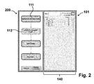
- FIG. 2 shows that in FIG. 1 1 and described above embodiment of the developing device 101 according to the invention in a second configuration 200.
- the creation process step 112 with the designation "V-ECU Configuration ready" is selected.
- the second display area 140 displays the configuration of the ECU program with associated basic software modules.
- the base software modules are created for further use, ie, for each existing base software module, 112 configurations may be made in the build process step.
- the basic software modules shown by way of example in the second display area 140 are Communication (COM), Operating System (OS), Runtime Environment (RTE) and NVRAM Manager (NVRAM: Non-Volatile Random-Access Memory).
- COM Communication
- OS Operating System
- RTE Runtime Environment
- NVRAM Manager Non-Volatile Random-Access Memory
- the RTE provides a runtime environment by which a common communication layer for different functions is specified among each other.
- the NvM provides services to ensure data storage and maintenance of non-volatile data to their individual specifications in a vehicle environment (see also AUTOSAR Specification of NVRAM Manager V3.1.0 R4.0 Rev2).
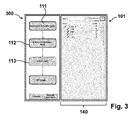
- FIG. 3 shows that in FIG. 1 In the third configuration 300 shown and described above, a development device 101 according to the invention is shown in a third configuration 300.
- the creation process step 113 labeled "V-ECU ready" is selected.
- a configuration of the controller program with the associated base software modules similar to the representation of the elements of the build process step 112 described above is displayed in the second display area 140.
- final work is performed on the base software modules. For example, a Runtime Environment (RTE) is generated and then an implementation of a ECU program is generated.
- RTE Runtime Environment
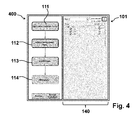
- FIG. 4 shows that in the FIGS. 1 to 3 shown embodiment of a developing device according to the invention in a configuration 400.
- the creation process step 114 of the name "VPU ready" is selected.
- the second Display area 114 displays the configuration of a Virtual Processing Unit (VPU) with the associated ports.
- VPU Virtual Processing Unit
- the VPU is configured and then created. Ie from a created V-ECU configuration ( Fig. 2 ) and after the generation of the basic software modules ( Fig. 3 ) is in the in FIG. 4
- the creation process step 114 shown generates the VPU, for example for a later simulation.
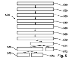
- FIG. 5 shows an embodiment of a method according to the invention 500.
- the method 500 is shown schematically as a flowchart. The method will be described with reference to the FIGS. 1 to 4 shown developing device 101 for carrying out the method 500 according to the invention described.
- steps need not be performed in this order, but can also be done in a different order. In particular, steps may be continued, interrupted, recorded, or repeated as other steps are added.
- FIG. 1 shown creation process of a control device program graphically reproduced.
- the reproduction takes place as in FIG. 1 shown in the form of a flowchart in the first portion 104 of the display unit 102.
- the flowchart comprises one or more in the creation process history consecutive creation process steps 111, 112, 113, 114, which are selectable by means of a control unit.
- an in FIG. 1 shown graphically reproduced creation process step 111 for example, selected by a user by means of an operating unit.
- the selected creation process step 111 is then optically highlighted, in particular in optical demarcation to a non-selected creation process step.
- step 540 after selecting a creation process step 111, at least one element 141 of a model of the control device program which is assigned to the selected creation process step 111 is displayed graphically in a second subarea 140 of the display unit 102.
- an element 141 can be selected, for example, by means of the operating unit, so that the selected element 141 is optically Demarcation to a non-selected element 143 is optically highlighted in a method step 560.
- a further method step 570 at least one in FIG. 1 shown creation process step 111 are executed.
- the execution 570 takes place here, for example, by selecting 571 of a graphically reproduced by the display unit 102 first execution field 135, which is provided as a first execution element.
- a single selected creation process step 111 can be executed.
- a further alternative method step 573 for example, by selecting a second execution field 136, a plurality of sequential creation process steps in the creation process process can be executed.
- a selected creation process step and at least one creation process step that precedes the selected creation process step in the creation process process can be executed.
- a selected creation process step and at least one creation process step following the selected creation process step in the creation process process can be executed.
- FIG. 6 shows a computer system 600 (eg, a computer client, server computer, etc.) comprising and / or consisting of several components for providing the development device according to the invention described above.
- Components such as a mouse 601, a keyboard 602, a hard disk 603 (or other memory with a computer readable medium), a display unit 604 coupled to the other components by means of a display connection unit 605, a central processing unit 606 (CPU) System memory 607 and an input / output unit 608 (I / O unit) are in FIG. 6 shown.
- the system bus connections 609 shown by connecting arrows, allow the central processing unit 606 to communicate with each component and control the execution of instructions from system memory 607 or hard disk 603, as well as the exchange of information between the components.
- the system memory 607 and / or the hard disk 603 may be provided as a computer-readable medium.
- the input / output unit 608 may be configured to facilitate communication of the computer system 600 with other computer systems, network components, or controllers.
- the mouse 601 and the keyboard 602 form a user interface 610 by means of which, for example, graphically displayed on the display unit 604 played items can be selected, edited, etc. can be.
- the operating unit 610 can also be used to execute an instruction of a program code resource stored on the system memory 607 and / or the hard disk 603 on the computer system.
- Any software components or functions described in this application may be implemented as software code that may be executed by a processor using any computer language such as C, Java, C ++, or Pearl using, for example, conventional or object-oriented methods.
- the software code may be stored as a series of instructions or commands on a computer-readable medium such as Random Access Memory (RAM), Read Only Memory (ROM), a magnetic medium such as a hard disk, or an optical medium such as a CD-ROM ,
Landscapes
- Engineering & Computer Science (AREA)
- Physics & Mathematics (AREA)
- General Physics & Mathematics (AREA)
- Automation & Control Theory (AREA)
- General Engineering & Computer Science (AREA)
- Stored Programmes (AREA)
Priority Applications (4)
| Application Number | Priority Date | Filing Date | Title |
|---|---|---|---|
| EP12160249.4A EP2642359A1 (de) | 2012-03-20 | 2012-03-20 | Entwicklungseinrichtung und Verfahren zum Erstellen eines Steuergeräteprogramms |
| CN2013100337260A CN103324472A (zh) | 2012-03-20 | 2013-01-30 | 用于构造控制装置程序的研发装置和方法 |
| US13/847,630 US20130253672A1 (en) | 2012-03-20 | 2013-03-20 | Development system and method for creating a control unit program |
| JP2013057685A JP5933474B2 (ja) | 2012-03-20 | 2013-03-21 | 制御装置プログラムの開発装置と作成方法 |
Applications Claiming Priority (1)
| Application Number | Priority Date | Filing Date | Title |
|---|---|---|---|
| EP12160249.4A EP2642359A1 (de) | 2012-03-20 | 2012-03-20 | Entwicklungseinrichtung und Verfahren zum Erstellen eines Steuergeräteprogramms |
Publications (1)
| Publication Number | Publication Date |
|---|---|
| EP2642359A1 true EP2642359A1 (de) | 2013-09-25 |
Family
ID=46000697
Family Applications (1)
| Application Number | Title | Priority Date | Filing Date |
|---|---|---|---|
| EP12160249.4A Withdrawn EP2642359A1 (de) | 2012-03-20 | 2012-03-20 | Entwicklungseinrichtung und Verfahren zum Erstellen eines Steuergeräteprogramms |
Country Status (4)
| Country | Link |
|---|---|
| US (1) | US20130253672A1 (enExample) |
| EP (1) | EP2642359A1 (enExample) |
| JP (1) | JP5933474B2 (enExample) |
| CN (1) | CN103324472A (enExample) |
Cited By (1)
| Publication number | Priority date | Publication date | Assignee | Title |
|---|---|---|---|---|
| DE102016206332A1 (de) | 2016-04-14 | 2017-10-19 | Volkswagen Aktiengesellschaft | Bedienvorrichtung und Verfahren zum Betreiben der Bedienvorrichtung |
Families Citing this family (4)
| Publication number | Priority date | Publication date | Assignee | Title |
|---|---|---|---|---|
| US10048972B2 (en) * | 2014-06-17 | 2018-08-14 | Continental Automotive Gmbh | Method for model-based generation of startup configurations of embedded systems |
| JP6356314B2 (ja) * | 2017-05-22 | 2018-07-11 | 東京エレクトロン株式会社 | 基板処理装置、編集方法及び記憶媒体 |
| CN108958725B (zh) * | 2018-07-06 | 2022-06-14 | 广州慧通编程教育科技有限公司 | 图形化模式编程平台生成方法、装置及计算机设备 |
| JP7151631B2 (ja) | 2019-06-11 | 2022-10-12 | 株式会社デンソー | 車両用制御装置、車両用表示システム、及び車両用表示制御方法 |
Citations (1)
| Publication number | Priority date | Publication date | Assignee | Title |
|---|---|---|---|---|
| DE10147341A1 (de) * | 2001-09-26 | 2003-04-24 | Voiceobjects Ag | Dynamischer Aufbau einer Dialogsteuerung aus Dialogobjekten |
Family Cites Families (11)
| Publication number | Priority date | Publication date | Assignee | Title |
|---|---|---|---|---|
| US5660547A (en) * | 1993-02-17 | 1997-08-26 | Atari Games Corporation | Scenario development system for vehicle simulators |
| JPH09319566A (ja) * | 1996-05-27 | 1997-12-12 | Toshiba Corp | 開発支援システムおよび開発支援方法 |
| JP2000020291A (ja) * | 1998-07-06 | 2000-01-21 | Toyota Motor Corp | 車両用プログラム開発支援方法および装置 |
| US7310784B1 (en) * | 2002-01-02 | 2007-12-18 | The Jellyvision Lab, Inc. | Methods for identifying cells in a path in a flowchart and for synchronizing graphical and textual views of a flowchart |
| US7353502B2 (en) * | 2002-07-03 | 2008-04-01 | The Mathworks, Inc. | System and method for creation of software components |
| DE102004039884A1 (de) * | 2003-08-20 | 2005-06-02 | Dspace Gmbh | Verfahren und System zur Beschreibung und Ausführung automatischer Tests |
| US7925994B2 (en) * | 2005-07-07 | 2011-04-12 | Microsoft Corporation | Task navigator including a user based navigation interface |
| DE102006044141A1 (de) * | 2006-09-15 | 2008-04-03 | Dspace Digital Signal Processing And Control Engineering Gmbh | Einrichtung und Verfahren zur Konfiguration eines Steuerungssystems |
| JP5060674B2 (ja) * | 2007-11-13 | 2012-10-31 | 株式会社キーエンス | 画像処理コントローラ用のプログラム作成装置 |
| ITMO20080148A1 (it) * | 2008-05-21 | 2009-11-22 | Fantuzzi Reggiane Spa | Sistema per la creazione e configurazione di una rete di dispositivi |
| GB2496803A (en) * | 2010-09-24 | 2013-05-22 | Research In Motion Ltd | Transitional view on a portable electronic device |
-
2012
- 2012-03-20 EP EP12160249.4A patent/EP2642359A1/de not_active Withdrawn
-
2013
- 2013-01-30 CN CN2013100337260A patent/CN103324472A/zh active Pending
- 2013-03-20 US US13/847,630 patent/US20130253672A1/en not_active Abandoned
- 2013-03-21 JP JP2013057685A patent/JP5933474B2/ja not_active Expired - Fee Related
Patent Citations (1)
| Publication number | Priority date | Publication date | Assignee | Title |
|---|---|---|---|---|
| DE10147341A1 (de) * | 2001-09-26 | 2003-04-24 | Voiceobjects Ag | Dynamischer Aufbau einer Dialogsteuerung aus Dialogobjekten |
Non-Patent Citations (1)
| Title |
|---|
| ETAS GMBH: "RTA-OS/RTA-RTE Real-Time AUTOSAR OS and RTE", INTERNET, 1 February 2009 (2009-02-01), XP002681535, Retrieved from the Internet <URL:http://www.etas.com/de/downloadcenter/7974-7975.php> [retrieved on 20110808] * |
Cited By (1)
| Publication number | Priority date | Publication date | Assignee | Title |
|---|---|---|---|---|
| DE102016206332A1 (de) | 2016-04-14 | 2017-10-19 | Volkswagen Aktiengesellschaft | Bedienvorrichtung und Verfahren zum Betreiben der Bedienvorrichtung |
Also Published As
| Publication number | Publication date |
|---|---|
| US20130253672A1 (en) | 2013-09-26 |
| JP2013196708A (ja) | 2013-09-30 |
| CN103324472A (zh) | 2013-09-25 |
| JP5933474B2 (ja) | 2016-06-08 |
Similar Documents
| Publication | Publication Date | Title |
|---|---|---|
| DE112005001031B4 (de) | Grafisches Bildschirmkonfigurationsgerüst für vereinheitlichte Prozesssteuerungssystemoberfläche | |
| EP2685382B1 (de) | Verfahren und Vorrichtung zum Erstellen und Testen eines Steuergeräteprogramms | |
| EP3082000A1 (de) | Verfahren und system zum testen eines mechatronischen systems | |
| DE19639424A1 (de) | Entwurfsverfahren für die Anlagentechnik und rechnergestütztes Projektierungssystem zur Verwendung bei diesem Verfahren | |
| EP2068214B1 (de) | Grafische Programmerstellung durch Ableiten des Prozesssteuerungsablaufes aus der Zuordnung dynamischer Grafikobjekte | |
| EP2799983B1 (de) | Flexible Aufteilung der I/O Kanäle einer Hardware Komponente | |
| DE102007036071A1 (de) | Verfahren und System zur Fehlerbeseitigung in einer Grafikpipeline-Teileinheit | |
| DE20321699U1 (de) | Rechner zum Durchführen eines Simulationsverfahrens für eine Bearbeitung eines Werkstücks durch eine Werkzeugmaschine | |
| DE102005026040A1 (de) | Parametrierung eines Simulations-Arbeitsmodells | |
| EP2990892A1 (de) | Verfahren zum Verbinden einer Eingabe/Ausgabe-Schnittstelle eines für das Testen eines Steuergeräts eingerichteten Testgeräts | |
| EP2330469B1 (de) | Verfahren und Entwicklungsumgebung zur Erzeugung eines ausführbaren Gesamtsteuerungsprogramms | |
| EP3398092A1 (de) | Verfahren zum konfigurieren einer co-simulation für ein gesamtsystem | |
| DE102017120016A1 (de) | Verfahren zur Konfiguration eines zum Testen eines elektronischen Steuergeräts eingerichteten Testgeräts sowie Konfigurationssystem | |
| EP2642359A1 (de) | Entwicklungseinrichtung und Verfahren zum Erstellen eines Steuergeräteprogramms | |
| DE69615544T2 (de) | Anzeigeverfahren und anzeigevorrichtung | |
| EP1658535B1 (de) | Verfahren zur graphischen projektierung der steuerung einer technischen anlage mit integrierter projektierung von bediengeräten | |
| DE19644481A1 (de) | Computergestütztes Arbeits- und Informationssystem und zugehöriger Baustein | |
| DE10046742A1 (de) | Vorrichtung und Verfahren für ein Fahrzeugentwurfssytem | |
| DE10324594A1 (de) | Verfahren zum Bereitstellen einer verbesserten Simulationsfähigkeit eines dynamischen Systems außerhalb der ursprünglichen Modellierungsumgebung | |
| DE102015221517A1 (de) | Bedienmodul zum Bedienen einer Maschine in der Lebensmittelindustrie | |
| EP2862075B1 (de) | Simulieren eines komplexen systems | |
| DE69804355T2 (de) | Dynamischer bedienoberflächenerzeuger | |
| EP2191338B1 (de) | System zur erstellung eines simulationsprogramms | |
| WO2005101148A2 (de) | Verfahren und system zur virtuellen inbetriebsetzung einer technischen anlage mit bevorzugter verwendung | |
| DE102004039884A1 (de) | Verfahren und System zur Beschreibung und Ausführung automatischer Tests |
Legal Events
| Date | Code | Title | Description |
|---|---|---|---|
| PUAI | Public reference made under article 153(3) epc to a published international application that has entered the european phase |
Free format text: ORIGINAL CODE: 0009012 |
|
| AK | Designated contracting states |
Kind code of ref document: A1 Designated state(s): AL AT BE BG CH CY CZ DE DK EE ES FI FR GB GR HR HU IE IS IT LI LT LU LV MC MK MT NL NO PL PT RO RS SE SI SK SM TR |
|
| AX | Request for extension of the european patent |
Extension state: BA ME |
|
| 17P | Request for examination filed |
Effective date: 20140325 |
|
| RBV | Designated contracting states (corrected) |
Designated state(s): AL AT BE BG CH CY CZ DE DK EE ES FI FR GB GR HR HU IE IS IT LI LT LU LV MC MK MT NL NO PL PT RO RS SE SI SK SM TR |
|
| RIN1 | Information on inventor provided before grant (corrected) |
Inventor name: VIKTOR, NESTEROW Inventor name: ESCHMANN, MARIO Inventor name: DEUTENBERG, GERNOT |
|
| 17Q | First examination report despatched |
Effective date: 20140815 |
|
| STAA | Information on the status of an ep patent application or granted ep patent |
Free format text: STATUS: THE APPLICATION IS DEEMED TO BE WITHDRAWN |
|
| 18D | Application deemed to be withdrawn |
Effective date: 20171003 |