EP2642112B1 - Einspritzventil mit in seiner Öffnungsposition anschlagfrei abbremsbarer Ventilnadel - Google Patents
Einspritzventil mit in seiner Öffnungsposition anschlagfrei abbremsbarer Ventilnadel Download PDFInfo
- Publication number
- EP2642112B1 EP2642112B1 EP13155422.2A EP13155422A EP2642112B1 EP 2642112 B1 EP2642112 B1 EP 2642112B1 EP 13155422 A EP13155422 A EP 13155422A EP 2642112 B1 EP2642112 B1 EP 2642112B1
- Authority
- EP
- European Patent Office
- Prior art keywords
- valve needle
- spring
- end position
- valve
- injection valve
- Prior art date
- Legal status (The legal status is an assumption and is not a legal conclusion. Google has not performed a legal analysis and makes no representation as to the accuracy of the status listed.)
- Not-in-force
Links
- 238000002347 injection Methods 0.000 title description 27
- 239000007924 injection Substances 0.000 title description 27
- 239000000446 fuel Substances 0.000 description 14
- 230000007704 transition Effects 0.000 description 7
- 238000002485 combustion reaction Methods 0.000 description 6
- 238000010586 diagram Methods 0.000 description 5
- 230000004913 activation Effects 0.000 description 1
- 230000001419 dependent effect Effects 0.000 description 1
- 238000011161 development Methods 0.000 description 1
- 230000018109 developmental process Effects 0.000 description 1
- 230000002349 favourable effect Effects 0.000 description 1
- 239000012530 fluid Substances 0.000 description 1
- 230000000750 progressive effect Effects 0.000 description 1
Images

Classifications
-
- F—MECHANICAL ENGINEERING; LIGHTING; HEATING; WEAPONS; BLASTING
- F02—COMBUSTION ENGINES; HOT-GAS OR COMBUSTION-PRODUCT ENGINE PLANTS
- F02M—SUPPLYING COMBUSTION ENGINES IN GENERAL WITH COMBUSTIBLE MIXTURES OR CONSTITUENTS THEREOF
- F02M61/00—Fuel-injectors not provided for in groups F02M39/00 - F02M57/00 or F02M67/00
- F02M61/16—Details not provided for in, or of interest apart from, the apparatus of groups F02M61/02 - F02M61/14
- F02M61/20—Closing valves mechanically, e.g. arrangements of springs or weights or permanent magnets; Damping of valve lift
- F02M61/205—Means specially adapted for varying the spring tension or assisting the spring force to close the injection-valve, e.g. with damping of valve lift
-
- F—MECHANICAL ENGINEERING; LIGHTING; HEATING; WEAPONS; BLASTING
- F02—COMBUSTION ENGINES; HOT-GAS OR COMBUSTION-PRODUCT ENGINE PLANTS
- F02M—SUPPLYING COMBUSTION ENGINES IN GENERAL WITH COMBUSTIBLE MIXTURES OR CONSTITUENTS THEREOF
- F02M51/00—Fuel-injection apparatus characterised by being operated electrically
- F02M51/06—Injectors peculiar thereto with means directly operating the valve needle
- F02M51/061—Injectors peculiar thereto with means directly operating the valve needle using electromagnetic operating means
-
- F—MECHANICAL ENGINEERING; LIGHTING; HEATING; WEAPONS; BLASTING
- F02—COMBUSTION ENGINES; HOT-GAS OR COMBUSTION-PRODUCT ENGINE PLANTS
- F02M—SUPPLYING COMBUSTION ENGINES IN GENERAL WITH COMBUSTIBLE MIXTURES OR CONSTITUENTS THEREOF
- F02M2200/00—Details of fuel-injection apparatus, not otherwise provided for
- F02M2200/30—Fuel-injection apparatus having mechanical parts, the movement of which is damped
- F02M2200/304—Fuel-injection apparatus having mechanical parts, the movement of which is damped using hydraulic means
-
- F—MECHANICAL ENGINEERING; LIGHTING; HEATING; WEAPONS; BLASTING
- F02—COMBUSTION ENGINES; HOT-GAS OR COMBUSTION-PRODUCT ENGINE PLANTS
- F02M—SUPPLYING COMBUSTION ENGINES IN GENERAL WITH COMBUSTIBLE MIXTURES OR CONSTITUENTS THEREOF
- F02M2200/00—Details of fuel-injection apparatus, not otherwise provided for
- F02M2200/30—Fuel-injection apparatus having mechanical parts, the movement of which is damped
- F02M2200/306—Fuel-injection apparatus having mechanical parts, the movement of which is damped using mechanical means
Definitions
- the present invention relates to an injection valve, in particular for injecting fuel into a combustion chamber.
- FIG. 1 shows a diagram by on the vertical axis a mass 1 of the injected fuel is plotted. On the horizontal axis a drive time 2 of the valve needle is applied. The diagram shows a mass profile 3 of the injected mass 1 of fuel over the activation period 2. Furthermore, a partial lift region 4, a transition region 5 and a full stroke region 6 are identified. At very short opening times in Operahub Schl 4, the stop of the valve needle is not reached.
- the valve needle For longer opening times in the full-stroke range 6, the valve needle, after it has reached the stop and as long as voltage is applied to the corresponding actuator for the valve needle, at the stop.
- the transition region 5 is located between the partial lifting region 4 and the full stroke region 6. In this transitional region 5, the valve needle is rebounded from the stop and thus moves in the closing direction at an increased speed. In the transition region in the case of previously known injection valves, this leads to a more or less pronounced decrease in the mass profile 3.
- WO01 / 38722 A1 discloses a brake spring on the nozzle side of a solenoid valve injection valve.
- the injection valve according to the invention with the features of claim 1 now makes it possible, in particular in a controlled over the actual opening and / or closing timing control of the valve needle to avoid a drop in the mass profile in the transition region. Due to the injector according to the invention without the axial valve needle stop, the amount of fuel injected increases steadily in the course of the driving time. This leads to a favorable control behavior. The disturbances in the transitional area are eliminated.
- an injection valve in particular for injecting fuel into a combustion chamber, comprising a housing with at least one injection opening. About this at least one injection port, the fuel from the injection valve is injected into the corresponding combustion chamber. In particular, this is a combustion chamber of an internal combustion engine.
- a linearly movable valve needle is provided in the housing, with the valve needle closing the at least one injection opening in a first end position and allowing a maximum flow of the fuel through the at least one injection opening in the second end position. Furthermore, an actuator for moving the valve needle between the two end positions is provided.
- the injection valve is designed so that the valve needle to the second end position is abruptly braked and abuts in the second end position at no, relative to the housing stationary stop.
- according to the invention eliminates the known axial end stop in the second end position for the valve needle. This avoids that in a transition region between a Operahub Council and a Vollhub Scheme the valve needle rebounds at the axial stop.
- a braking device for stop-free braking of the valve needle at the second end position.
- the valve needle is braked shortly before reaching the second end position over a certain Nietumble away, so that the valve needle comes to a standstill in the second end position, without hitting an axial stop.
- this braking device comprises a spring.
- the spring is particularly preferably designed as a spiral spring and is according to the invention on a side remote from the injection opening of the valve needle in the housing. Shortly before reaching the second end position, the valve needle runs on this spring and is thus braked.
- the spring is designed as a progressive spring. This is possible for example by a variable design of the individual gradients of the coil spring.
- the braking device preferably comprises a hydraulic pad.
- This hydraulic pad is preferably designed as a fuel-filled chamber in the housing of the injection valve.
- the hydraulic fluid, in particular the fuel, in the hydraulic cushion is displaced by means of the movement of the valve needle and thus the valve needle is braked.
- the valve needle runs when moving in the direction of the second end position on the spring and preferably in addition to the hydraulic pad.
- the invention does not speak of an axial stop, since the spring and preferably in addition the hydraulic pad on which the valve needle runs, in the axial direction is movable and flexible.
- the spring used, and preferably additionally the hydraulic pad still has a certain mobility or flexibility in the axial direction even after reaching the second end position.
- the braking device is designed to drive the actuator and thus can decelerate the valve needle in the second end position.
- the injection valve is designed as a magnetic injection valve.
- the actuator includes a solenoid for moving the valve pins.
- the braking device controls the solenoid such that a braking force acts on the valve needle.
- the valve needle is braked to the second end position by means of a special drive curve for the solenoid.
- the braking device for example, the spring, the hydraulic pad and the driving of the actuator with each other.
- FIG. 2 shows for an inventive injection valve 100, as shown in FIG. 3 is shown, a diagram with the mass profile 3. On the vertical axis, the mass 1 of the injected fuel is recorded. The control period 2 of the valve needle is recorded on the horizontal axis. The mass profile 3 shows the respective mass flow of fuel through the at least one injection opening of the injection valve. Furthermore, a partial lift area 4, a transition area 5 and a full lift area 6 are indicated.
- valve needles in injection valves according to the prior art in the second end position strike against an axial stop fixed relative to the housing. This bounces the previously known Valve needles back and there is the kink in the mass curve 3 in the transition region 5 (see FIG. 1 ).
Landscapes
- Engineering & Computer Science (AREA)
- Chemical & Material Sciences (AREA)
- Combustion & Propulsion (AREA)
- Mechanical Engineering (AREA)
- General Engineering & Computer Science (AREA)
- Physics & Mathematics (AREA)
- Electromagnetism (AREA)
- Fuel-Injection Apparatus (AREA)
Description
- Die vorliegende Erfindung betrifft ein Einspritzventil, insbesondere zum Einspritzen von Brennstoff in einen Brennraum.
- Vorbekannte Einspritzventile, insbesondere Magneteinspritzventile, für Brennkraftmaschinen weisen eine linear bewegbare Ventilnadel auf, die je nach ihrer Stellung eine Spritzöffnung öffnet oder schließt. Dabei ist für die Ventilnadel ein Anschlag vorhanden, der den Öffnungsweg der Ventilnadel begrenzt.
Figur 1 zeigt ein Diagramm, indem auf der vertikalen Achse eine Masse 1 des eingespritzten Brennstoffs aufgetragen ist. Auf der horizontalen Achse ist eine Ansteuerdauer 2 der Ventilnadel aufgetragen. Das Diagramm zeigt einen Massenverlauf 3 der eingespritzten Masse 1 an Brennstoff über der Ansteuerdauer 2. Des Weiteren sind ein Teilhubbereich 4, ein Übergangsbereich 5 und ein Vollhubbereich 6 gekennzeichnet. Bei sehr kurzen Öffnungszeiten im Teilhubbereich 4 wird der Anschlag der Ventilnadel nicht erreicht. Bei längeren Öffnungszeiten im Vollhubbereich 6 liegt die Ventilnadel, nachdem sie den Anschlag erreicht hat und solange Spannung am entsprechenden Aktuator für die Ventilnadel anliegt, am Anschlag an. Zwischen dem Teilhubbereich 4 und dem Vollhubbereich 6 befindet sich der Übergangsbereich 5. In diesem Übergangsbereich 5 wird die Ventilnadel vom Anschlag zurückgeprellt und bewegt sich somit mit erhöhter Geschwindigkeit in Schließrichtung. Dies führt im Übergangsbereich bei vorbekannten Einspritzventilen zu einer mehr oder weniger ausgeprägten Abnahme im Masseverlauf 3. -
DE 10 2004 035313 A sowieEP 1 559 908 A offenbaren anschlagfrei abbremsbare Düsennadeln, jedoch indirekt hydraulisch von einem Piezoaktuator betätigt. -
WO01/38722 A1 - Das erfindungsgemäße Einspritzventil mit den Merkmalen des Anspruchs 1 ermöglicht es nun, insbesondere bei einer über den tatsächlichen Öffnungs- und/oder Schließzeitpunkt geregelten Ansteuerung der Ventilnadel, im Übergangsbereich ein Abfallen des Masseverlaufs zu vermeiden. Durch das erfindungsgemäße Einspritzventil ohne den axialen Ventilnadelanschlag erhöht sich die Menge an eingespritztem Brennstoff stetig im Verlauf der Ansteuerungsdauer. Dies führt zu einem günstigen Regelverhalten. Die Störungen im Übergangsbereich entfallen dabei. Diese Vorteile werden erreicht durch ein Einspritzventil, insbesondere zum Einspritzen von Brennstoff in einen Brennraum, umfassend ein Gehäuse mit zumindest einer Spritzöffnung. Über diese zumindest eine Spritzöffnung wird der Brennstoff vom Einspritzventil in den entsprechenden Brennraum eingespritzt. Insbesondere handelt es sich hierbei um einen Brennraum einer Brennkraftmaschine. In dem Gehäuse ist eine linear bewegliche Ventilnadel vorgesehen, wobei die Ventilnadel in einer ersten Endposition die zumindest eine Spritzöffnung verschließt und in der zweiten Endposition einen maximalen Durchfluss des Brennstoffs durch die zumindest eine Spritzöffnung ermöglicht. Des Weiteren ist ein Aktor zum Bewegen der Ventilnadel zwischen den beiden Endpositionen vorgesehen. Das Einspritzventil ist dabei so ausgebildet, dass die Ventilnadel zur zweiten Endposition hin anschlagsfrei abbremsbar ist und in der zweiten Endposition an keinem, gegenüber dem Gehäuse ortsfesten Anschlag anliegt. Insbesondere entfällt erfindungsgemäß der vorbekannte axiale Endanschlag in der zweiten Endposition für die Ventilnadel. Dadurch wird vermieden, dass in einem Übergangsbereich zwischen einem Teilhubbereich und einem Vollhubbereich die Ventilnadel an dem axialen Anschlag abprallt.
- Die Unteransprüche zeigen bevorzugte Weiterbildungen der Erfindung.
- Erfindungsgemäß ist eine Bremseinrichtung zum anschlagsfreien Abbremsen der Ventilnadel an der zweiten Endposition vorgesehen. Mittels dieser Bremseinrichtung wird die Ventilnadel kurz vor Erreichen der zweiten Endposition über eine gewisse Nietstrecke hinweg abgebremst, so dass die Ventilnadel in der zweiten Endposition zum Stillstand kommt, ohne an einem axialen Anschlag anzuschlagen.
- Erfindungsgemäß umfasst diese Bremseinrichtung eine Feder. Die Feder wird besonders bevorzugt als Spiralfeder ausgebildet und befindet sich erfindungsgemäß auf einer der Spritzöffnung abgewandten Seite der Ventilnadel im Gehäuse. Kurz vor Erreichen der zweiten Endposition läuft die Ventilnadel auf diese Feder auf und wird somit abgebremst. Erfindungsgemäß ist vorgesehen, dass die Feder als progressive Feder ausgebildet ist. Dies ist beispielsweise durch eine variable Gestaltung der einzelnen Steigungen der Spiralfeder möglich.
- Alternativ oder zusätzlich umfasst die Bremseinrichtung bevorzugt ein hydraulisches Polster. Dieses hydraulische Polster ist bevorzugt als eine mit Brennstoff gefüllte Kammer im Gehäuse des Einspritzventils ausgebildet. Bei einer Bewegung der Ventilnadel in Richtung der zweiten Endposition wird mittels der Bewegung der Ventilnadel das hydraulische Fluid, insbesondere der Brennstoff, im hydraulischen Polster verdrängt und somit die Ventilnadel abgebremst. Insbesondere ist dabei vorgesehen, dass beim Verdrängen des Brennstoffes aus dem hydraulischen Polster der Brennstoff über ein Drosselventil aus der Kammer ausgeleitet wird.
- Bei Verwendung der Bremseinrichtung, ausgebildet als Feder und bevorzugt zusätzlich umfassend ein hydraulisches Polster, läuft die Ventilnadel bei Bewegung in Richtung der zweiten Endposition auf die Feder und bevorzugt zusätzlich auf das hydraulische Polster auf. Hierbei wird erfindungsgemäß nicht von einem axialen Anschlag gesprochen, da die Feder und bevorzugt zusätzlich das hydraulische Polster, auf das die Ventilnadel aufläuft, in Axialrichtung beweglich und flexibel ist. Insbesondere weist die verwendete Feder und bevorzugt zusätzlich das hydraulische Polster auch nach Erreichen der zweiten Endposition noch eine gewisse Beweglichkeit bzw. Flexibilität in axialer Richtung auf.
- Des Weiteren ist, nicht Gegenstand der Erfindung, vorgesehen, dass die Bremseinrichtung zum Ansteuern des Aktors ausgebildet ist und somit die Ventilnadel in der zweiten Endposition abbremsen kann.
- Erfindungsgemäß ist das Einspritzventil als Magneteinspritzventil ausgebildet. Dementsprechend umfasst der Aktor eine Magnetspule zum Bewegen der Ventilnadeln. Nicht Gegenstand der Erfindung, ist vorgesehen, dass die Bremseinrichtung die Magnetspule derart ansteuert, so dass eine Bremskraft auf die Ventilnadel wirkt. Dabei wird mittels einer speziellen Ansteuerkurve für die Magnetspule die Ventilnadel zur zweiten Endposition hin abgebremst.
- Nicht Gegenstand der Erfindung, ist es auch vorgesehen, die verschiedenen Ausbildungen der Bremseinrichtung, beispielsweise die Feder, das hydraulische Polster und das Ansteuern des Aktuators, miteinander zu kombinieren.
- Nachfolgend wird ein Ausführungsbeispiel der Erfindung unter Bezugnahme auf die begleitende Zeichnung im Detail beschrieben. Dabei zeigt:
-
Figur 1 ein Diagramm mit einem Masseverlauf für ein Einspritzventil nach dem Stand der Technik, -
Figur 2 ein Diagramm mit einem Masseverlauf für ein erfindungsgemäßes Einspritzventil gemäß dem Ausführungsbeispiel, und -
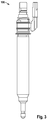
Figur 3 ein erfindungsgemäßes Einspritzventil gemäß dem Ausführungsbeispiel. -
Figur 2 zeigt für ein erfindungsgemäßes Einspritzventil 100, wie es inFigur 3 dargestellt ist, ein Diagramm mit dem Masseverlauf 3. Auf der vertikalen Achse ist die Masse 1 des eingespritzten Brennstoffes aufgezeichnet. Auf der horizontalen Achse ist die Ansteuerdauer 2 der Ventilnadel aufgezeichnet. Der Masseverlauf 3 zeigt den jeweiligen Massedurchfluss an Brennstoff durch die zumindest eine Spritzöffnung des Einspritzventils. Des Weiteren sind ein Teilhubbereich 4, ein Übergangsbereich 5 und ein Vollhubbereich 6 gekennzeichnet. - Wie einleitend beschrieben, schlagen die Ventilnadeln bei Einspritzventilen nach dem Stand der Technik in der zweiten Endposition gegen einen axialen, gegenüber dem Gehäuse ortsfesten Anschlag. Dadurch prallen die vorbekannten Ventilnadeln zurück und es entsteht der Knick im Masseverlauf 3 im Übergangsbereich 5 (siehe
Figur 1 ). - Bei dem erfindungsgemäßen Einspritzventil entfällt der gegenüber dem Gehäuse ortsfeste axiale Anschlag in der zweiten Endposition der Ventilnadel. Dadurch wird das Rückprallen der Ventilnadel vermieden und es entsteht, wie in
Figur 2 gezeigt, ein kontinuierlicher Anstieg des Masseverlaufs 3 über die gesamte Ansteuerdauer 2.
Claims (4)
- Einspritzventil, insbesondere zum Einspritzen von Brennstoff in einen Brennraum, umfassend- ein Gehäuse mit zumindest einer Spritzöffnung,- eine im Gehäuse linearbewegliche Ventilnadel, wobei die Ventilnadel in einer ersten Endposition die zumindest eine Spritzöffnung verschließt und in der zweiten Endposition einen maximalen Durchfluss des Brennstoffs durch die zumindest eine Spritzöffnung ermöglicht, und- einen Aktor zum Bewegen der Ventilnadel zwischen den beiden Endpositionen,- wobei die Ventilnadel zur zweiten Endposition hin anschlagsfrei abbremsbar ist und in der zweiten Endposition an keinem Anschlag anliegt,dadurch gekennzeichnet,
dass das Einspritzventil als Magneteinspritzventil ausgebildet ist und der Aktor eine Magnetspule zum Bewegen der Ventilnadel umfasst und dass eine Bremseinrichtung zum anschlagsfreien Abbremsen der Ventilnadel an der zweiten Endposition vorgesehen ist, wobei die Bremseinrichtung eine Feder umfasst und die Feder derart angeordnet ist, dass kurz vor Erreichen der zweiten Endposition die Ventilnadel auf diese Feder aufläuft und somit abgebremst wird, wobei die Feder sich auf einer der Spritzöffnung abgewandten Seite der Ventilnadel im Gehäuse befindet und die Feder als progressive Feder ausgebildet ist. - Einspritzventil nach Anspruch 1, dadurch gekennzeichnet, dass die Feder als Spiralfeder ausgebildet ist.
- Einspritzventil nach Anspruch 1 oder 2, dadurch gekennzeichnet, dass die Bremseinrichtung zusätzlich ein hydraulisches Polster umfasst.
- Einspritzventil nach Anspruch 3, dadurch gekennzeichnet, dass das hydraulische Polster als eine mit Brennstoff gefüllte Kammer im Gehäuse ausgebildet ist.
Applications Claiming Priority (1)
| Application Number | Priority Date | Filing Date | Title |
|---|---|---|---|
| DE201210204297 DE102012204297A1 (de) | 2012-03-19 | 2012-03-19 | Einspritzventil |
Publications (2)
| Publication Number | Publication Date |
|---|---|
| EP2642112A1 EP2642112A1 (de) | 2013-09-25 |
| EP2642112B1 true EP2642112B1 (de) | 2016-04-20 |
Family
ID=47710036
Family Applications (1)
| Application Number | Title | Priority Date | Filing Date |
|---|---|---|---|
| EP13155422.2A Not-in-force EP2642112B1 (de) | 2012-03-19 | 2013-02-15 | Einspritzventil mit in seiner Öffnungsposition anschlagfrei abbremsbarer Ventilnadel |
Country Status (2)
| Country | Link |
|---|---|
| EP (1) | EP2642112B1 (de) |
| DE (1) | DE102012204297A1 (de) |
Citations (4)
| Publication number | Priority date | Publication date | Assignee | Title |
|---|---|---|---|---|
| JPH11270428A (ja) * | 1998-03-24 | 1999-10-05 | Zexel:Kk | 筒内噴射装置 |
| WO2001038722A1 (de) * | 1999-11-27 | 2001-05-31 | Robert Bosch Gmbh | Brennstoffeinspritzventil |
| WO2011125946A1 (ja) * | 2010-04-01 | 2011-10-13 | 日立オートモティブシステムズ株式会社 | 電磁式燃料噴射弁 |
| EP2527637A1 (de) * | 2011-05-23 | 2012-11-28 | Continental Automotive GmbH | Injektor zum Einspritzen von Flüssigkeit |
Family Cites Families (4)
| Publication number | Priority date | Publication date | Assignee | Title |
|---|---|---|---|---|
| US6363913B1 (en) * | 2000-06-09 | 2002-04-02 | Caterpillar Inc. | Solid state lift for micrometering in a fuel injector |
| DE102004004006A1 (de) * | 2004-01-27 | 2005-08-11 | Robert Bosch Gmbh | Integrierter hydraulischer Druckübersetzer für Kraftstoffinjektoren an Hochdruckspeichereinspritzsystemen |
| DE102004035313A1 (de) * | 2004-07-21 | 2006-02-16 | Robert Bosch Gmbh | Kraftstoffinjektor mit zweistufigem Übersetzer |
| JP4968180B2 (ja) * | 2008-05-27 | 2012-07-04 | 株式会社デンソー | インジェクタ |
-
2012
- 2012-03-19 DE DE201210204297 patent/DE102012204297A1/de not_active Withdrawn
-
2013
- 2013-02-15 EP EP13155422.2A patent/EP2642112B1/de not_active Not-in-force
Patent Citations (5)
| Publication number | Priority date | Publication date | Assignee | Title |
|---|---|---|---|---|
| JPH11270428A (ja) * | 1998-03-24 | 1999-10-05 | Zexel:Kk | 筒内噴射装置 |
| WO2001038722A1 (de) * | 1999-11-27 | 2001-05-31 | Robert Bosch Gmbh | Brennstoffeinspritzventil |
| WO2011125946A1 (ja) * | 2010-04-01 | 2011-10-13 | 日立オートモティブシステムズ株式会社 | 電磁式燃料噴射弁 |
| EP2554829A1 (de) * | 2010-04-01 | 2013-02-06 | Hitachi Automotive Systems, Ltd. | Elektromagnetisches kraftstoffeinspritzventil |
| EP2527637A1 (de) * | 2011-05-23 | 2012-11-28 | Continental Automotive GmbH | Injektor zum Einspritzen von Flüssigkeit |
Also Published As
| Publication number | Publication date |
|---|---|
| DE102012204297A1 (de) | 2013-09-19 |
| EP2642112A1 (de) | 2013-09-25 |
Similar Documents
| Publication | Publication Date | Title |
|---|---|---|
| EP2220360B1 (de) | Schaltventil für injektoren | |
| DE102015218768B3 (de) | Elektromagnetischer Aktor, elektromagnetisches Ventil und Kraftstoffhochdruckpumpe | |
| EP3535486B1 (de) | Brennstoffeinspritzventil zum einspritzen eines gasförmigen und/oder flüssigen brennstoffs | |
| EP2634412A1 (de) | Einspritzventil | |
| DE102008000907A1 (de) | Magnetventil mit mehrteiligem Anker ohne Ankerführung | |
| DE102012217322A1 (de) | Einspritzventil | |
| EP2100026B1 (de) | Kraftstoffinjektor mit magnetventil mit kugelsitz | |
| DE102016220326A1 (de) | Ventil zum Zumessen eines gasförmigen oder flüssigen Kraftstoffs | |
| DE102011003443A1 (de) | Kraftstoffinjektor | |
| DE102005053115A1 (de) | Optimierte Ankergruppenführung für Magnetventile | |
| EP1402170B1 (de) | Steuermodul für einen injektor eines speichereinspritzsystems | |
| WO2008110408A1 (de) | Kraftstoffinjektor mit verbessertem steuerventil | |
| DE102012222043A1 (de) | Kraftstoffinjektor | |
| DE102009027727A1 (de) | Ventilanordnung | |
| DE102008014251A1 (de) | Einspritzventil für Direkteinspritzung | |
| DE10009037A1 (de) | Steuerventil für eine Kraftstoff-Einspritzdüse | |
| WO2007128607A1 (de) | Magnetventil mit geflutetem ankerraum | |
| EP3346121B1 (de) | Magnetventil für ein kraftstoffeinspritzsystem und kraftstoffhochdruckpumpe | |
| DE102012220027A1 (de) | Schaltventil für einen Kraftstoffinjektor | |
| EP2580462B1 (de) | Einspritzventil mit direkt- und servoantrieb | |
| EP2642112A1 (de) | Einspritzventil mit in seiner Öffnungsposition anschlagsfrei abbremsbarer Ventilnadel | |
| EP1967727A2 (de) | Kraftstoffinjektor mit einer verbesserten Ausführung eines Steuerventils zur Steuerung einer Düsennadel | |
| WO2013189639A1 (de) | Einspritzventil | |
| EP3921536B1 (de) | Injektoreinheit zum einspritzen von kraftstoff und verfahren zum betreiben einer solchen | |
| DE102015215536A1 (de) | Ventil zum Zumessen eines Fluids |
Legal Events
| Date | Code | Title | Description |
|---|---|---|---|
| PUAI | Public reference made under article 153(3) epc to a published international application that has entered the european phase |
Free format text: ORIGINAL CODE: 0009012 |
|
| AK | Designated contracting states |
Kind code of ref document: A1 Designated state(s): AL AT BE BG CH CY CZ DE DK EE ES FI FR GB GR HR HU IE IS IT LI LT LU LV MC MK MT NL NO PL PT RO RS SE SI SK SM TR |
|
| AX | Request for extension of the european patent |
Extension state: BA ME |
|
| 17P | Request for examination filed |
Effective date: 20140325 |
|
| RBV | Designated contracting states (corrected) |
Designated state(s): AL AT BE BG CH CY CZ DE DK EE ES FI FR GB GR HR HU IE IS IT LI LT LU LV MC MK MT NL NO PL PT RO RS SE SI SK SM TR |
|
| 17Q | First examination report despatched |
Effective date: 20140825 |
|
| RIC1 | Information provided on ipc code assigned before grant |
Ipc: F02M 61/20 20060101AFI20150921BHEP Ipc: F02M 51/06 20060101ALI20150921BHEP |
|
| GRAP | Despatch of communication of intention to grant a patent |
Free format text: ORIGINAL CODE: EPIDOSNIGR1 |
|
| INTG | Intention to grant announced |
Effective date: 20151109 |
|
| GRAS | Grant fee paid |
Free format text: ORIGINAL CODE: EPIDOSNIGR3 |
|
| GRAA | (expected) grant |
Free format text: ORIGINAL CODE: 0009210 |
|
| AK | Designated contracting states |
Kind code of ref document: B1 Designated state(s): AL AT BE BG CH CY CZ DE DK EE ES FI FR GB GR HR HU IE IS IT LI LT LU LV MC MK MT NL NO PL PT RO RS SE SI SK SM TR |
|
| REG | Reference to a national code |
Ref country code: GB Ref legal event code: FG4D Free format text: NOT ENGLISH |
|
| REG | Reference to a national code |
Ref country code: CH Ref legal event code: EP |
|
| REG | Reference to a national code |
Ref country code: AT Ref legal event code: REF Ref document number: 792732 Country of ref document: AT Kind code of ref document: T Effective date: 20160515 |
|
| REG | Reference to a national code |
Ref country code: IE Ref legal event code: FG4D Free format text: LANGUAGE OF EP DOCUMENT: GERMAN |
|
| REG | Reference to a national code |
Ref country code: DE Ref legal event code: R096 Ref document number: 502013002622 Country of ref document: DE |
|
| REG | Reference to a national code |
Ref country code: LT Ref legal event code: MG4D |
|
| REG | Reference to a national code |
Ref country code: NL Ref legal event code: MP Effective date: 20160420 |
|
| PG25 | Lapsed in a contracting state [announced via postgrant information from national office to epo] |
Ref country code: FI Free format text: LAPSE BECAUSE OF FAILURE TO SUBMIT A TRANSLATION OF THE DESCRIPTION OR TO PAY THE FEE WITHIN THE PRESCRIBED TIME-LIMIT Effective date: 20160420 Ref country code: LT Free format text: LAPSE BECAUSE OF FAILURE TO SUBMIT A TRANSLATION OF THE DESCRIPTION OR TO PAY THE FEE WITHIN THE PRESCRIBED TIME-LIMIT Effective date: 20160420 Ref country code: NL Free format text: LAPSE BECAUSE OF FAILURE TO SUBMIT A TRANSLATION OF THE DESCRIPTION OR TO PAY THE FEE WITHIN THE PRESCRIBED TIME-LIMIT Effective date: 20160420 Ref country code: PL Free format text: LAPSE BECAUSE OF FAILURE TO SUBMIT A TRANSLATION OF THE DESCRIPTION OR TO PAY THE FEE WITHIN THE PRESCRIBED TIME-LIMIT Effective date: 20160420 Ref country code: NO Free format text: LAPSE BECAUSE OF FAILURE TO SUBMIT A TRANSLATION OF THE DESCRIPTION OR TO PAY THE FEE WITHIN THE PRESCRIBED TIME-LIMIT Effective date: 20160720 |
|
| PG25 | Lapsed in a contracting state [announced via postgrant information from national office to epo] |
Ref country code: SE Free format text: LAPSE BECAUSE OF FAILURE TO SUBMIT A TRANSLATION OF THE DESCRIPTION OR TO PAY THE FEE WITHIN THE PRESCRIBED TIME-LIMIT Effective date: 20160420 Ref country code: HR Free format text: LAPSE BECAUSE OF FAILURE TO SUBMIT A TRANSLATION OF THE DESCRIPTION OR TO PAY THE FEE WITHIN THE PRESCRIBED TIME-LIMIT Effective date: 20160420 Ref country code: ES Free format text: LAPSE BECAUSE OF FAILURE TO SUBMIT A TRANSLATION OF THE DESCRIPTION OR TO PAY THE FEE WITHIN THE PRESCRIBED TIME-LIMIT Effective date: 20160420 Ref country code: GR Free format text: LAPSE BECAUSE OF FAILURE TO SUBMIT A TRANSLATION OF THE DESCRIPTION OR TO PAY THE FEE WITHIN THE PRESCRIBED TIME-LIMIT Effective date: 20160721 Ref country code: PT Free format text: LAPSE BECAUSE OF FAILURE TO SUBMIT A TRANSLATION OF THE DESCRIPTION OR TO PAY THE FEE WITHIN THE PRESCRIBED TIME-LIMIT Effective date: 20160822 Ref country code: RS Free format text: LAPSE BECAUSE OF FAILURE TO SUBMIT A TRANSLATION OF THE DESCRIPTION OR TO PAY THE FEE WITHIN THE PRESCRIBED TIME-LIMIT Effective date: 20160420 Ref country code: LV Free format text: LAPSE BECAUSE OF FAILURE TO SUBMIT A TRANSLATION OF THE DESCRIPTION OR TO PAY THE FEE WITHIN THE PRESCRIBED TIME-LIMIT Effective date: 20160420 |
|
| REG | Reference to a national code |
Ref country code: DE Ref legal event code: R097 Ref document number: 502013002622 Country of ref document: DE |
|
| PG25 | Lapsed in a contracting state [announced via postgrant information from national office to epo] |
Ref country code: SK Free format text: LAPSE BECAUSE OF FAILURE TO SUBMIT A TRANSLATION OF THE DESCRIPTION OR TO PAY THE FEE WITHIN THE PRESCRIBED TIME-LIMIT Effective date: 20160420 Ref country code: DK Free format text: LAPSE BECAUSE OF FAILURE TO SUBMIT A TRANSLATION OF THE DESCRIPTION OR TO PAY THE FEE WITHIN THE PRESCRIBED TIME-LIMIT Effective date: 20160420 Ref country code: CZ Free format text: LAPSE BECAUSE OF FAILURE TO SUBMIT A TRANSLATION OF THE DESCRIPTION OR TO PAY THE FEE WITHIN THE PRESCRIBED TIME-LIMIT Effective date: 20160420 Ref country code: RO Free format text: LAPSE BECAUSE OF FAILURE TO SUBMIT A TRANSLATION OF THE DESCRIPTION OR TO PAY THE FEE WITHIN THE PRESCRIBED TIME-LIMIT Effective date: 20160420 Ref country code: EE Free format text: LAPSE BECAUSE OF FAILURE TO SUBMIT A TRANSLATION OF THE DESCRIPTION OR TO PAY THE FEE WITHIN THE PRESCRIBED TIME-LIMIT Effective date: 20160420 |
|
| REG | Reference to a national code |
Ref country code: FR Ref legal event code: PLFP Year of fee payment: 5 |
|
| PLBE | No opposition filed within time limit |
Free format text: ORIGINAL CODE: 0009261 |
|
| STAA | Information on the status of an ep patent application or granted ep patent |
Free format text: STATUS: NO OPPOSITION FILED WITHIN TIME LIMIT |
|
| PG25 | Lapsed in a contracting state [announced via postgrant information from national office to epo] |
Ref country code: SM Free format text: LAPSE BECAUSE OF FAILURE TO SUBMIT A TRANSLATION OF THE DESCRIPTION OR TO PAY THE FEE WITHIN THE PRESCRIBED TIME-LIMIT Effective date: 20160420 |
|
| 26N | No opposition filed |
Effective date: 20170123 |
|
| PG25 | Lapsed in a contracting state [announced via postgrant information from national office to epo] |
Ref country code: SI Free format text: LAPSE BECAUSE OF FAILURE TO SUBMIT A TRANSLATION OF THE DESCRIPTION OR TO PAY THE FEE WITHIN THE PRESCRIBED TIME-LIMIT Effective date: 20160420 Ref country code: BE Free format text: LAPSE BECAUSE OF NON-PAYMENT OF DUE FEES Effective date: 20170228 |
|
| PG25 | Lapsed in a contracting state [announced via postgrant information from national office to epo] |
Ref country code: MC Free format text: LAPSE BECAUSE OF FAILURE TO SUBMIT A TRANSLATION OF THE DESCRIPTION OR TO PAY THE FEE WITHIN THE PRESCRIBED TIME-LIMIT Effective date: 20160420 |
|
| REG | Reference to a national code |
Ref country code: CH Ref legal event code: PL |
|
| GBPC | Gb: european patent ceased through non-payment of renewal fee |
Effective date: 20170215 |
|
| PG25 | Lapsed in a contracting state [announced via postgrant information from national office to epo] |
Ref country code: LI Free format text: LAPSE BECAUSE OF NON-PAYMENT OF DUE FEES Effective date: 20170228 Ref country code: CH Free format text: LAPSE BECAUSE OF NON-PAYMENT OF DUE FEES Effective date: 20170228 |
|
| REG | Reference to a national code |
Ref country code: IE Ref legal event code: MM4A |
|
| PG25 | Lapsed in a contracting state [announced via postgrant information from national office to epo] |
Ref country code: LU Free format text: LAPSE BECAUSE OF NON-PAYMENT OF DUE FEES Effective date: 20170215 |
|
| REG | Reference to a national code |
Ref country code: FR Ref legal event code: PLFP Year of fee payment: 6 Ref country code: BE Ref legal event code: MM Effective date: 20170228 |
|
| PG25 | Lapsed in a contracting state [announced via postgrant information from national office to epo] |
Ref country code: GB Free format text: LAPSE BECAUSE OF NON-PAYMENT OF DUE FEES Effective date: 20170215 Ref country code: IE Free format text: LAPSE BECAUSE OF NON-PAYMENT OF DUE FEES Effective date: 20170215 |
|
| PG25 | Lapsed in a contracting state [announced via postgrant information from national office to epo] |
Ref country code: MT Free format text: LAPSE BECAUSE OF FAILURE TO SUBMIT A TRANSLATION OF THE DESCRIPTION OR TO PAY THE FEE WITHIN THE PRESCRIBED TIME-LIMIT Effective date: 20160420 |
|
| PG25 | Lapsed in a contracting state [announced via postgrant information from national office to epo] |
Ref country code: AL Free format text: LAPSE BECAUSE OF FAILURE TO SUBMIT A TRANSLATION OF THE DESCRIPTION OR TO PAY THE FEE WITHIN THE PRESCRIBED TIME-LIMIT Effective date: 20160420 |
|
| REG | Reference to a national code |
Ref country code: AT Ref legal event code: MM01 Ref document number: 792732 Country of ref document: AT Kind code of ref document: T Effective date: 20180215 |
|
| PG25 | Lapsed in a contracting state [announced via postgrant information from national office to epo] |
Ref country code: AT Free format text: LAPSE BECAUSE OF NON-PAYMENT OF DUE FEES Effective date: 20180215 |
|
| PGFP | Annual fee paid to national office [announced via postgrant information from national office to epo] |
Ref country code: IT Payment date: 20190222 Year of fee payment: 7 |
|
| PGFP | Annual fee paid to national office [announced via postgrant information from national office to epo] |
Ref country code: FR Payment date: 20190221 Year of fee payment: 7 |
|
| PG25 | Lapsed in a contracting state [announced via postgrant information from national office to epo] |
Ref country code: HU Free format text: LAPSE BECAUSE OF FAILURE TO SUBMIT A TRANSLATION OF THE DESCRIPTION OR TO PAY THE FEE WITHIN THE PRESCRIBED TIME-LIMIT; INVALID AB INITIO Effective date: 20130215 |
|
| PGFP | Annual fee paid to national office [announced via postgrant information from national office to epo] |
Ref country code: DE Payment date: 20190423 Year of fee payment: 7 |
|
| PG25 | Lapsed in a contracting state [announced via postgrant information from national office to epo] |
Ref country code: BG Free format text: LAPSE BECAUSE OF FAILURE TO SUBMIT A TRANSLATION OF THE DESCRIPTION OR TO PAY THE FEE WITHIN THE PRESCRIBED TIME-LIMIT Effective date: 20160420 |
|
| PG25 | Lapsed in a contracting state [announced via postgrant information from national office to epo] |
Ref country code: CY Free format text: LAPSE BECAUSE OF NON-PAYMENT OF DUE FEES Effective date: 20160420 |
|
| PG25 | Lapsed in a contracting state [announced via postgrant information from national office to epo] |
Ref country code: MK Free format text: LAPSE BECAUSE OF FAILURE TO SUBMIT A TRANSLATION OF THE DESCRIPTION OR TO PAY THE FEE WITHIN THE PRESCRIBED TIME-LIMIT Effective date: 20160420 |
|
| PG25 | Lapsed in a contracting state [announced via postgrant information from national office to epo] |
Ref country code: TR Free format text: LAPSE BECAUSE OF FAILURE TO SUBMIT A TRANSLATION OF THE DESCRIPTION OR TO PAY THE FEE WITHIN THE PRESCRIBED TIME-LIMIT Effective date: 20160420 |
|
| PG25 | Lapsed in a contracting state [announced via postgrant information from national office to epo] |
Ref country code: IS Free format text: LAPSE BECAUSE OF FAILURE TO SUBMIT A TRANSLATION OF THE DESCRIPTION OR TO PAY THE FEE WITHIN THE PRESCRIBED TIME-LIMIT Effective date: 20160820 |
|
| REG | Reference to a national code |
Ref country code: DE Ref legal event code: R119 Ref document number: 502013002622 Country of ref document: DE |
|
| PG25 | Lapsed in a contracting state [announced via postgrant information from national office to epo] |
Ref country code: DE Free format text: LAPSE BECAUSE OF NON-PAYMENT OF DUE FEES Effective date: 20200901 Ref country code: FR Free format text: LAPSE BECAUSE OF NON-PAYMENT OF DUE FEES Effective date: 20200229 |
|
| PG25 | Lapsed in a contracting state [announced via postgrant information from national office to epo] |
Ref country code: IT Free format text: LAPSE BECAUSE OF NON-PAYMENT OF DUE FEES Effective date: 20200215 |