EP2642076B1 - Connecting system for metal components and cmc components, a turbine blade retaining system and a rotating component retaining system - Google Patents
Connecting system for metal components and cmc components, a turbine blade retaining system and a rotating component retaining system Download PDFInfo
- Publication number
- EP2642076B1 EP2642076B1 EP13158942.6A EP13158942A EP2642076B1 EP 2642076 B1 EP2642076 B1 EP 2642076B1 EP 13158942 A EP13158942 A EP 13158942A EP 2642076 B1 EP2642076 B1 EP 2642076B1
- Authority
- EP
- European Patent Office
- Prior art keywords
- component
- metal
- retaining pin
- thermal expansion
- aperture
- Prior art date
- Legal status (The legal status is an assumption and is not a legal conclusion. Google has not performed a legal analysis and makes no representation as to the accuracy of the status listed.)
- Active
Links
Images

Classifications
-
- F—MECHANICAL ENGINEERING; LIGHTING; HEATING; WEAPONS; BLASTING
- F01—MACHINES OR ENGINES IN GENERAL; ENGINE PLANTS IN GENERAL; STEAM ENGINES
- F01D—NON-POSITIVE DISPLACEMENT MACHINES OR ENGINES, e.g. STEAM TURBINES
- F01D5/00—Blades; Blade-carrying members; Heating, heat-insulating, cooling or antivibration means on the blades or the members
- F01D5/12—Blades
- F01D5/28—Selecting particular materials; Particular measures relating thereto; Measures against erosion or corrosion
- F01D5/284—Selection of ceramic materials
-
- F—MECHANICAL ENGINEERING; LIGHTING; HEATING; WEAPONS; BLASTING
- F01—MACHINES OR ENGINES IN GENERAL; ENGINE PLANTS IN GENERAL; STEAM ENGINES
- F01D—NON-POSITIVE DISPLACEMENT MACHINES OR ENGINES, e.g. STEAM TURBINES
- F01D5/00—Blades; Blade-carrying members; Heating, heat-insulating, cooling or antivibration means on the blades or the members
- F01D5/30—Fixing blades to rotors; Blade roots ; Blade spacers
- F01D5/3007—Fixing blades to rotors; Blade roots ; Blade spacers of axial insertion type
-
- F—MECHANICAL ENGINEERING; LIGHTING; HEATING; WEAPONS; BLASTING
- F01—MACHINES OR ENGINES IN GENERAL; ENGINE PLANTS IN GENERAL; STEAM ENGINES
- F01D—NON-POSITIVE DISPLACEMENT MACHINES OR ENGINES, e.g. STEAM TURBINES
- F01D5/00—Blades; Blade-carrying members; Heating, heat-insulating, cooling or antivibration means on the blades or the members
- F01D5/30—Fixing blades to rotors; Blade roots ; Blade spacers
- F01D5/3053—Fixing blades to rotors; Blade roots ; Blade spacers by means of pins
-
- F—MECHANICAL ENGINEERING; LIGHTING; HEATING; WEAPONS; BLASTING
- F01—MACHINES OR ENGINES IN GENERAL; ENGINE PLANTS IN GENERAL; STEAM ENGINES
- F01D—NON-POSITIVE DISPLACEMENT MACHINES OR ENGINES, e.g. STEAM TURBINES
- F01D5/00—Blades; Blade-carrying members; Heating, heat-insulating, cooling or antivibration means on the blades or the members
- F01D5/30—Fixing blades to rotors; Blade roots ; Blade spacers
- F01D5/3084—Fixing blades to rotors; Blade roots ; Blade spacers the blades being made of ceramics
-
- F—MECHANICAL ENGINEERING; LIGHTING; HEATING; WEAPONS; BLASTING
- F05—INDEXING SCHEMES RELATING TO ENGINES OR PUMPS IN VARIOUS SUBCLASSES OF CLASSES F01-F04
- F05D—INDEXING SCHEME FOR ASPECTS RELATING TO NON-POSITIVE-DISPLACEMENT MACHINES OR ENGINES, GAS-TURBINES OR JET-PROPULSION PLANTS
- F05D2260/00—Function
- F05D2260/30—Retaining components in desired mutual position
-
- F—MECHANICAL ENGINEERING; LIGHTING; HEATING; WEAPONS; BLASTING
- F05—INDEXING SCHEMES RELATING TO ENGINES OR PUMPS IN VARIOUS SUBCLASSES OF CLASSES F01-F04
- F05D—INDEXING SCHEME FOR ASPECTS RELATING TO NON-POSITIVE-DISPLACEMENT MACHINES OR ENGINES, GAS-TURBINES OR JET-PROPULSION PLANTS
- F05D2300/00—Materials; Properties thereof
- F05D2300/50—Intrinsic material properties or characteristics
- F05D2300/502—Thermal properties
- F05D2300/5021—Expansivity
- F05D2300/50212—Expansivity dissimilar
-
- F—MECHANICAL ENGINEERING; LIGHTING; HEATING; WEAPONS; BLASTING
- F05—INDEXING SCHEMES RELATING TO ENGINES OR PUMPS IN VARIOUS SUBCLASSES OF CLASSES F01-F04
- F05D—INDEXING SCHEME FOR ASPECTS RELATING TO NON-POSITIVE-DISPLACEMENT MACHINES OR ENGINES, GAS-TURBINES OR JET-PROPULSION PLANTS
- F05D2300/00—Materials; Properties thereof
- F05D2300/60—Properties or characteristics given to material by treatment or manufacturing
- F05D2300/603—Composites; e.g. fibre-reinforced
- F05D2300/6033—Ceramic matrix composites [CMC]
-
- F—MECHANICAL ENGINEERING; LIGHTING; HEATING; WEAPONS; BLASTING
- F05—INDEXING SCHEMES RELATING TO ENGINES OR PUMPS IN VARIOUS SUBCLASSES OF CLASSES F01-F04
- F05D—INDEXING SCHEME FOR ASPECTS RELATING TO NON-POSITIVE-DISPLACEMENT MACHINES OR ENGINES, GAS-TURBINES OR JET-PROPULSION PLANTS
- F05D2300/00—Materials; Properties thereof
- F05D2300/60—Properties or characteristics given to material by treatment or manufacturing
- F05D2300/612—Foam
Definitions
- the present invention relates generally to power generation systems and more specifically to connecting system for metal component and ceramic matrix composite (CMC) components in power generation systems.
- CMC ceramic matrix composite
- Ceramic matrix composites offer high material temperature capability. In the gas turbine field, however, CMC components often require attachment to, or engagement with, lower temperature metallic gas turbine components. Problems associated with the attachment of known silicon carbide CMC's to metallic components include wear, oxidation (due to ionic transfer with metal), stress concentration (from clamping loads), transition to thick section fabrication, and fiber damage in creating holes in the CMC's.
- US 5405245 describes a turbine blade having a preestablished rate of thermal expansion attached to a turbine wheel having a greater preestablished rate of thermal expansion
- the turbine wheel includes a pair of side walls having a groove formed therebetween and a pair of axially aligned holes radially positioned therein.
- the turbine blade has a root portion having a bore positioned therein.
- a pin having a preestablished rate of thermal expansion being substantially equal to the rate of thermal expansion of the blade is positioned within the axially aligned holes and the bore attaches the blade to the turbine wheel.
- the present invention resides in a connecting system for connecting a metal component and a ceramic matrix composite and in a turbine blade retaining system as defined in the appended claims.
- a connecting system for connecting a metal component and a CMC component that do not suffer from the drawbacks in the prior art.
- One advantage of certain embodiments of the present disclosure includes a retaining pin that fits tight in the connecting system. Another advantage of an embodiment of the present disclosure may include a retaining pin that has a coefficient of thermal expansion that is similar to the first component or metal component. Yet another advantage of an embodiment of the present disclosure may include a retaining pin that has a coefficient of thermal expansion that is greater than that of the second component or CMC component. Another advantage of an embodiment of the present disclosure may include a CMC component having an aperture that is greater than the retaining pin to allow for coefficient of thermal expansion (CTE) mismatch. Another advantage of an embodiment of the present disclosure may be high temperature metal foam bushing that creates contact with the retaining pin, CMC component, and metal holder throughout operation.
- CTE coefficient of thermal expansion
- Yet another advantage of an embodiment of the present disclosure may be that the high temperature metal foam bushing reduces stress in CMC airfoil stem. Another advantage of an embodiment of the present disclosure may be that the CMC airfoils are more tightly secured in the metal holders thereby reducing vibration in the power generation system. Another advantage of an embodiment of the present disclosure can be that it provides a more consistent loading in the CMC airfoil stem pin hole or aperture. Another advantage of an embodiment of the present disclosure may be that it allows for retrofit of the existing fleet of power generation systems with CMC airfoils without having to replace or retool the metal holders in the existing power generation system. Another advantage of various embodiments of the present disclosure may be reduced low cycle fatigue considerations on the CMC bucket stem. Another advantage of an embodiment of the present disclosure may be a system for joining two materials with differing coefficients of thermal expansion.
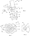
- Power generation systems 10 include, but are not limited to, gas turbines, steam turbines, and other turbine assemblies. An embodiment of the disclosure is shown in FIGS. 1-3 , but the present disclosure is not limited to the illustrated structure.
- FIG. 1 shows an example of a power generation system 10, in this embodiment a gas turbine engine, having a compressor section 12, a combustor section 14 and a turbine section 16.
- a gas turbine engine having a compressor section 12, a combustor section 14 and a turbine section 16.
- the turbine section 16 there are alternating rows of stationary airfoils 18 (commonly referred to as vanes) and rotating airfoils 20 (commonly referred to as blades).
- Each row of blades 20 is formed by a plurality of airfoils 20 attached to a disc 22 provided on a rotor 24.
- the blades 20 can extend radially outward from the discs 22 and terminate in a region known as the blade tip 26.
- Each row of vanes 18 is formed by attaching a plurality of vanes 18 to a vane carrier 28.
- the vanes 18 can extend radially inward from the inner peripheral surface of the vane carrier 28.
- the vane carrier 28 is attached to an outer casing 32, which encloses the turbine section 16 of the engine.
- high temperature, high velocity gases flow through the rows of vanes 18 and blades 20 in the turbine section 16.
- the connecting system 100 retains the rotating airfoils 20 or blades in the casing 32 of the power generation system 10.
- the connecting system 100 includes a retaining pin 122, a metal foam bushing 116, a first aperture 108 disposed in the metal component 112.
- the connecting system 100 includes a second aperture 110 disposed in the CMC component 114.
- the first aperture 108 and the second aperture 110 are configured to form a through-hole 132 (see FIG. 4 ) when the metal component 112 and the CMC component 114 are engaged.
- the retaining pin 122 and metal foam bushing 116 are operably arranged within the through-hole 132 to connect the metal component 112 and the CMC component 114.
- the connecting system 100 is a turbine connecting system 101.
- the turbine connecting system 130 includes a reinforcing pin 112, a metal foam bushing 116, a first aperture 108 disposed in an airfoil segment or stem 104 and a second aperture 110 disposed in a holder segment 106.
- the metal foam bushing 116 includes an inner diameter 134 and an outer diameter 136 defining a bushing aperture 120 for receiving the reinforcing pin 112.
- the first aperture 108 of the airfoil stem 104 and the second aperture 110 of the holder segment 106 form a through-hole 132 (see FIG. 4 ) for receiving the metal foam bushing 116 and the retaining pin 112 (not shown in FIG.
- the retaining pin 122 and metal foam bushing 116 are arranged and disposed in the through-hole 122 to connect the airfoil stem 104 and the holder segment 106 to form the turbine blade retaining system 130.
- the airfoil segment or stem 104 is a CMC component.
- the airfoil 102 is formed as a monolithic CMC component, having the airfoil, airfoil platform 118, and airfoil stem 104 formed as single CMC component.
- the retaining pin 122 In operation, to retain the rotating part in place the retaining pin 122 will need to have a higher CTE than the CMC airfoil stem 104 that it is situated in. In one embodiment, the material and size of the retaining pin 122 are chosen to provide desired sheer strength to prevent airfoil stem 104 pull load/creep.
- the inner diameter 134 of the metal foam bushing 116 is sized such that the reinforcing pin 122 can grow or expand into the metal foam bushing 116 without yielding the bushing.
- the retaining pin 122 will have a CTE that is approximately greater than or equal to the CTE of the CMC component.
- the retaining pin 122 is selected from the same material as the metal component.
- FIG. 3 is a cross-section of a rotating component retaining system 200.
- the rotating component is an airfoil 20 or blade (see FIG. 1 ).
- the rotating component retaining system 200 includes a retaining pin 122, a first aperture 108 (see FIG. 2 ) disposed in a first component 112 (see FIG. 3 ), a second aperture 110 (see FIG. 2 ) disposed in a second component 114, and a bushing 116.
- the first and second apertures 108 and 110 are also referred to as pin holes.
- the first component 112 has a first coefficient of thermal expansion.
- the second component 114 has a second coefficient of thermal expansion.
- the bushing 116 has a third coefficient of thermal expansion, the third coefficient of thermal expansion being intermediate to the first coefficient of thermal expansion and second coefficient of thermal expansion.
- the first aperture 108 and the second aperture 110 form a through-hole 132 (see FIG. 4 ) or pin hole for receiving the bushing 116 and the retaining pin 122 when the first component 112 and the second component 114 are engaged.
- the bushing 116 includes a bushing aperture 120 for receiving the retaining pin 122.
- the retaining pin 122 and bushing 116 are operably arranged within the through-hole 132 to connect the first component 112 and the second component 114 to form the rotating component retaining system 200.
- the first coefficient of thermal expansion of the first component 112 is approximately greater than or equal to the second coefficient of thermal expansion of the second component 114.
- the third coefficient of thermal expansion of the bushing 116 is less than or approximately equal to the second coefficient of thermal expansion of the second component 114.
- the bushing 116 is an open celled or closed celled metal foam bushing.
- the first component 112 is a metal component, such as, but not limited to, a holder segment 106 (see FIG. 3 ).
- the first component 112 is a metal component and is constructed from material selected from, but not limited to, titanium, nickel, iron, cobalt, chromium, alloys thereof, and combinations thereof.
- the second component 114 is a CMC component, such as, but not limited to, an airfoil stem 104 (see FIG. 3 ).
- the CMC component is selected from any variety of CMC materials used in the art, such as, but not limited to, SiC/SiC, SiC/Si-SiC, SiC/C, SiC/Si 3 N 4 and oxide-based materials such as Al 2 O 3 /Al 2 O 3 -SiO 2
- the CMC includes a matrix material selected from SiC, SiN, and combinations thereof.
- the metal foam bushing is selected from a material that is approximately that of the first component 112 or holder segment 106.
- the metal foam bushing includes materials selected from, but not limited to titanium, nickel, iron, cobalt, chromium, alloys thereof, and combinations thereof.
- the metal foam bushing 116 is constructed from metal foam material available under the trademark FECRALLOYTM FeCrAlY, (by Porvair Fuel Cell Technology, 700 Shepherd Street, Hendersonville, NC) which is an iron-chromium-aluminum-yttrium alloy with a nominal composition by weight %, respectively, of 72.8% iron, 22% chromium, 5% aluminum, and 0.1% yttrium and 0.1% zirconium.
- FECRALLOYTM FeCrAlY by Porvair Fuel Cell Technology, 700 Shepherd Street, Hendersonville, NC
- FECRALLOYTM FeCrAlY an iron-chromium-aluminum-yttrium alloy with a nominal composition by weight %, respectively, of 72.8% iron, 22% chromium, 5% aluminum, and 0.1% yttrium and 0.1% zirconium.
- Metallic foam for the metal foam bushing 116 can be made by any suitable method, such as, but not limited to, chemical vapor deposition, investment casting, and slurry coating.
- the chemical vapor deposition technique includes producing a metal gas and desublimating the gas onto a polymer substrate, heating the substrate volatilizing the polymer which leaves a metallic replication of the substrate intact, and then again heating to sinter the metallic material to produce the metallic foam.
- the investment casting technique involves utilizing a polymer substrate as a preform within a mold cavity and filing the mold cavity with a mold material and volatizing the polymer substrate and then pouring molten metal into the mold cavity where heat and pressure are applied.
- the slurry coating technique involves producing a paint-like mixture of fine metal powders and polymer binders and coating this paint-like mixture on an open cell polymer foam using processes such as spin impregnation, roller impregnation, and spray impregnation.
- the impregnated open cell polymer foam is compressed to expel excess slurry, then dried and fired to burn out the polymer foam, and sintered to produce the metallic foam.
- the rigid metallic foam produced using any of the above described techniques has a plurality of interconnecting voids having substantially the same structural configurations as the polymer foam which was the starting material.
- the metallic particles used include, but are not limited to, titanium, nickel, iron, cobalt, chromium, alloys thereof, and combinations thereof.
- the metal foam can have a low density, between 5% and 40% of the solid parent metal, and high strength.
- the term "compliant" or “compliancy” is here meant as having a modulus of elasticity which accommodates interference fit during assembly and differential thermal expansion between the retaining pin 122 and CMC component or airfoil stem 104, without transferring forces which result in damage to the CMC airfoil stem 104.
- the three dimensional network structure with high surface area to density and a high melting temperature over 1000°C allows for use the metal foam bushing 116 at operating temperatures of power generation systems.
- the metal foam bushing 116 compresses to provide a good fit between the outer surface of the retaining pin 122 and the through-hole 132 outer surface.
- the yield stress or compression stress at which the material will irreversibly begin to compress the metal foam can be varied depending upon the density of the foam.
- metal foam having a density on the order of 3-4% relative density will have a yield strength of about 1 MPa.
- a material having a relative density of about 4.5-6% will have a yield strength of approximately 2 MPa, while a material having a relative density greater than about 6% will have a yield strength of about 3 MPa or greater.
- the metal foam bushing 116 is selected from a closed cell metal foam.
- the relative density of foam is greater than that of the open cell metal foam.
- the stress strain behavior of a closed-cell metal foam bushing is different than that of the open cell metal foam.
- a suitable example of a closed-cell metal foam bushing 116 is but not limited to, a nickel closed cell metal foam.
- the thickness of the metal foam bushing 116 is such that the metal foam bushing 116 does not plastically deform under rotating and operational conditions. In one embodiment, the thickness is based on density of the metal foam bushing, and the metal foam bushing 116 has a relative density of approximately 3% to approximately 50%, or alternatively approximately 10% to approximately 35%, or alternatively approximately 20% to approximately 30%.
Landscapes
- Engineering & Computer Science (AREA)
- Mechanical Engineering (AREA)
- General Engineering & Computer Science (AREA)
- Chemical & Material Sciences (AREA)
- Ceramic Engineering (AREA)
- Materials Engineering (AREA)
- Turbine Rotor Nozzle Sealing (AREA)
- Connection Of Plates (AREA)
Applications Claiming Priority (1)
| Application Number | Priority Date | Filing Date | Title |
|---|---|---|---|
| US13/423,658 US9175571B2 (en) | 2012-03-19 | 2012-03-19 | Connecting system for metal components and CMC components, a turbine blade retaining system and a rotating component retaining system |
Publications (3)
| Publication Number | Publication Date |
|---|---|
| EP2642076A2 EP2642076A2 (en) | 2013-09-25 |
| EP2642076A3 EP2642076A3 (en) | 2014-01-08 |
| EP2642076B1 true EP2642076B1 (en) | 2018-01-17 |
Family
ID=47915443
Family Applications (1)
| Application Number | Title | Priority Date | Filing Date |
|---|---|---|---|
| EP13158942.6A Active EP2642076B1 (en) | 2012-03-19 | 2013-03-13 | Connecting system for metal components and cmc components, a turbine blade retaining system and a rotating component retaining system |
Country Status (5)
| Country | Link |
|---|---|
| US (1) | US9175571B2 (enExample) |
| EP (1) | EP2642076B1 (enExample) |
| JP (1) | JP6118147B2 (enExample) |
| CN (1) | CN103321687B (enExample) |
| RU (1) | RU2623342C2 (enExample) |
Families Citing this family (30)
| Publication number | Priority date | Publication date | Assignee | Title |
|---|---|---|---|---|
| FR2990462B1 (fr) * | 2012-05-14 | 2014-05-30 | Snecma | Dispositif d'attache d'aubes sur un disque de rotor de turbomachine |
| US9470092B2 (en) * | 2013-01-02 | 2016-10-18 | General Electric Company | System and method for attaching a rotating blade in a turbine |
| EP3052763B1 (en) * | 2013-09-30 | 2020-07-15 | United Technologies Corporation | A nonmetallic airfoil with a compliant attachment |
| CN106164416B (zh) | 2013-11-25 | 2019-09-27 | 安萨尔多能源英国知识产权有限公司 | 用于涡轮机的基于模块化结构的叶片组件 |
| CN106103901B (zh) | 2013-12-20 | 2019-04-16 | 安萨尔多能源英国知识产权有限公司 | 转子叶片或导叶组件 |
| US20180195402A1 (en) * | 2014-02-05 | 2018-07-12 | United Technologies Corporation | Disposable fan platform fairing |
| US9932831B2 (en) * | 2014-05-09 | 2018-04-03 | United Technologies Corporation | High temperature compliant metallic elements for low contact stress ceramic support |
| US10267156B2 (en) * | 2014-05-29 | 2019-04-23 | General Electric Company | Turbine bucket assembly and turbine system |
| CN106574510A (zh) * | 2014-08-22 | 2017-04-19 | 西门子能源公司 | 具有单独的缘板支撑系统的模块化涡轮机叶片 |
| US10280768B2 (en) | 2014-11-12 | 2019-05-07 | Rolls-Royce North American Technologies Inc. | Turbine blisk including ceramic matrix composite blades and methods of manufacture |
| US9909430B2 (en) | 2014-11-13 | 2018-03-06 | Rolls-Royce North American Technologies Inc. | Turbine disk assembly including seperable platforms for blade attachment |
| CA2915234A1 (en) | 2015-01-13 | 2016-07-13 | Rolls-Royce Corporation | Turbine wheel with clamped blade attachment |
| GB201514139D0 (en) * | 2015-08-11 | 2015-09-23 | Rolls Royce Plc | A datum feature for a composite component |
| AT518289B1 (de) * | 2016-02-18 | 2018-06-15 | Andritz Hydro Gmbh | Peltonrad |
| US20180051880A1 (en) * | 2016-08-18 | 2018-02-22 | General Electric Company | Combustor assembly for a turbine engine |
| US10294954B2 (en) | 2016-11-09 | 2019-05-21 | Rolls-Royce North American Technologies Inc. | Composite blisk |
| US10577951B2 (en) | 2016-11-30 | 2020-03-03 | Rolls-Royce North American Technologies Inc. | Gas turbine engine with dovetail connection having contoured root |
| US10563665B2 (en) | 2017-01-30 | 2020-02-18 | Rolls-Royce North American Technologies, Inc. | Turbomachine stage and method of making same |
| CN106738497A (zh) * | 2017-03-14 | 2017-05-31 | 青岛金科模具有限公司 | 花纹块及轮胎模具 |
| CN110869239B (zh) * | 2017-07-07 | 2022-02-22 | 麦格纳座椅公司 | 压力感测系统和具有该压力感测系统的座椅垫 |
| US10619514B2 (en) * | 2017-10-18 | 2020-04-14 | Rolls-Royce Corporation | Ceramic matrix composite assembly with compliant pin attachment features |
| US11802486B2 (en) * | 2017-11-13 | 2023-10-31 | General Electric Company | CMC component and fabrication using mechanical joints |
| WO2019108203A1 (en) * | 2017-11-30 | 2019-06-06 | Siemens Aktiengesellschaft | Hybrid ceramic matrix composite components with intermediate cushion structure |
| US10801350B2 (en) * | 2018-02-23 | 2020-10-13 | Rolls-Royce Corporation | Actively cooled engine assembly with ceramic matrix composite components |
| US10752556B2 (en) * | 2018-10-18 | 2020-08-25 | Rolls-Royce High Temperature Composites Inc. | Method of processing a ceramic matrix composite (CMC) component |
| US11046620B2 (en) | 2018-10-18 | 2021-06-29 | Rolls-Royce Corporation | Method of processing a ceramic matrix composite (CMC) component |
| US20220003202A1 (en) * | 2018-11-01 | 2022-01-06 | General Electric Company | Wind turbine rotor blade joint constructed of dissimilar materials |
| FR3098542B1 (fr) * | 2019-07-10 | 2023-11-24 | Safran Ceram | Ensemble de pièces de turbomachine |
| IT202100029963A1 (it) * | 2021-11-26 | 2023-05-26 | Ge Avio Srl | Motore a turbina a gas comprendente un complesso di pale rotanti. |
| CN116900247B (zh) * | 2023-09-14 | 2023-12-05 | 中国航发北京航空材料研究院 | 陶瓷基复合材料与单晶高温合金复合构件的制备方法 |
Family Cites Families (31)
| Publication number | Priority date | Publication date | Assignee | Title |
|---|---|---|---|---|
| US3923422A (en) * | 1974-10-17 | 1975-12-02 | United Technologies Corp | Taper lining for composite blade root attachment |
| US4084922A (en) | 1976-12-27 | 1978-04-18 | Electric Power Research Institute, Inc. | Turbine rotor with pin mounted ceramic turbine blades |
| US4273824A (en) * | 1979-05-11 | 1981-06-16 | United Technologies Corporation | Ceramic faced structures and methods for manufacture thereof |
| JPS5748320U (enExample) * | 1980-09-04 | 1982-03-18 | ||
| DE3110096C2 (de) | 1981-03-16 | 1983-05-19 | MTU Motoren- und Turbinen-Union München GmbH, 8000 München | Turbinenlaufschaufel für Gasturbinentriebwerke |
| JP2924163B2 (ja) * | 1990-10-31 | 1999-07-26 | いすゞ自動車株式会社 | ピストン及びその製造方法 |
| US5240377A (en) | 1992-02-25 | 1993-08-31 | Williams International Corporation | Composite fan blade |
| FR2697284B1 (fr) * | 1992-10-27 | 1995-01-27 | Europ Propulsion | Procédé de fabrication d'une roue de turbine à aubes insérées et roue obtenue par le procédé. |
| DE4237031C1 (de) | 1992-11-03 | 1994-02-10 | Mtu Muenchen Gmbh | Verstellbare Leitschaufel |
| FR2699497B1 (fr) * | 1992-12-23 | 1995-03-10 | Eurocopter France | Dispositif de liaison pale-moyeu à attache feuilletée, pale de rotor munie d'une telle attache, et rotor équipé de telles pales. |
| US5405245A (en) | 1993-11-29 | 1995-04-11 | Solar Turbines Incorporated | Ceramic blade attachment system |
| US5580219A (en) * | 1995-03-06 | 1996-12-03 | Solar Turbines Incorporated | Ceramic blade attachment system |
| US5593275A (en) | 1995-08-01 | 1997-01-14 | General Electric Company | Variable stator vane mounting and vane actuation system for an axial flow compressor of a gas turbine engine |
| US5735673A (en) | 1996-12-04 | 1998-04-07 | United Technologies Corporation | Turbine engine rotor blade pair |
| US6086327A (en) | 1999-01-20 | 2000-07-11 | Mack Plastics Corporation | Bushing for a jet engine vane |
| KR20010049364A (ko) | 1999-06-14 | 2001-06-15 | 제이 엘. 차스킨, 버나드 스나이더, 아더엠. 킹 | 시일 조립체 |
| US6213719B1 (en) * | 1999-07-28 | 2001-04-10 | United Technologies Corporation | Bar wedge preload apparatus for a propeller blade |
| US6431781B1 (en) | 2000-06-15 | 2002-08-13 | Honeywell International, Inc. | Ceramic to metal joint assembly |
| US6670021B2 (en) | 2001-11-14 | 2003-12-30 | General Electric Company | Monolithic ceramic attachment bushing incorporated into a ceramic matrix composite component and related method |
| US6725787B2 (en) | 2002-03-11 | 2004-04-27 | Weyerhaeuser Company | Refractory vessel and lining therefor |
| GB2392477A (en) | 2002-08-24 | 2004-03-03 | Alstom | Turbocharger |
| US6878246B2 (en) | 2003-04-02 | 2005-04-12 | Alcoa, Inc. | Nickel foam pin connections for inert anodes |
| JP3858096B2 (ja) * | 2003-07-09 | 2006-12-13 | 独立行政法人産業技術総合研究所 | 金属又はセラミックス含有発泡焼結体の製造方法 |
| DE10358888B4 (de) | 2003-12-16 | 2018-12-27 | Schaeffler Technologies AG & Co. KG | Brennkraftmaschine mit einer hydraulischen Vorrichtung zur Drehwinkelverstellung einer Nockenwelle gegenüber einer Kurbelwelle |
| DE10359730A1 (de) | 2003-12-19 | 2005-07-14 | Mtu Aero Engines Gmbh | Turbomaschine, insbesondere Gasturbine |
| JP4731920B2 (ja) | 2005-01-20 | 2011-07-27 | 本田技研工業株式会社 | ロータ |
| US7563071B2 (en) | 2005-08-04 | 2009-07-21 | Siemens Energy, Inc. | Pin-loaded mounting apparatus for a refractory component in a combustion turbine engine |
| US7523616B2 (en) | 2005-11-30 | 2009-04-28 | General Electric Company | Methods and apparatuses for assembling a gas turbine engine |
| US7445427B2 (en) | 2005-12-05 | 2008-11-04 | General Electric Company | Variable stator vane assembly and bushing thereof |
| US20090068008A1 (en) | 2007-09-07 | 2009-03-12 | Shimadzu Corporation | Fastening structure and rotary vacuum pump |
| US8534989B2 (en) | 2010-01-19 | 2013-09-17 | Honeywell International Inc. | Multi-piece turbocharger bearing |
-
2012
- 2012-03-19 US US13/423,658 patent/US9175571B2/en active Active
-
2013
- 2013-03-13 EP EP13158942.6A patent/EP2642076B1/en active Active
- 2013-03-18 JP JP2013054735A patent/JP6118147B2/ja active Active
- 2013-03-18 RU RU2013111943A patent/RU2623342C2/ru active
- 2013-03-19 CN CN201310088260.4A patent/CN103321687B/zh active Active
Non-Patent Citations (1)
| Title |
|---|
| None * |
Also Published As
| Publication number | Publication date |
|---|---|
| RU2013111943A (ru) | 2014-09-27 |
| RU2623342C2 (ru) | 2017-06-23 |
| US20130243601A1 (en) | 2013-09-19 |
| US9175571B2 (en) | 2015-11-03 |
| JP6118147B2 (ja) | 2017-04-19 |
| JP2013194739A (ja) | 2013-09-30 |
| CN103321687B (zh) | 2016-06-08 |
| EP2642076A2 (en) | 2013-09-25 |
| CN103321687A (zh) | 2013-09-25 |
| EP2642076A3 (en) | 2014-01-08 |
Similar Documents
| Publication | Publication Date | Title |
|---|---|---|
| EP2642076B1 (en) | Connecting system for metal components and cmc components, a turbine blade retaining system and a rotating component retaining system | |
| US7905016B2 (en) | System for forming a gas cooled airfoil for use in a turbine engine | |
| EP2469045B1 (en) | Turbine airfoil components containing ceramic-based materials | |
| JP5970182B2 (ja) | セラミック基材料と金属材料とから成る部品の製造工程 | |
| EP2469031B1 (en) | Turbine airfoil components containing ceramic-based materials and processes therefor | |
| EP2469026B1 (en) | Component containing a ceramic-based material and a compliant coating system | |
| US8876481B2 (en) | Turbine airfoil component assembly for use in a gas turbine engine and methods for fabricating same | |
| US7968144B2 (en) | System for applying a continuous surface layer on porous substructures of turbine airfoils | |
| CN106917024B (zh) | 燃气涡轮机部件和用于制造这种燃气涡轮机部件的方法 | |
| EP3372790A1 (en) | Component having a hybrid coating system and method for forming a component |
Legal Events
| Date | Code | Title | Description |
|---|---|---|---|
| PUAI | Public reference made under article 153(3) epc to a published international application that has entered the european phase |
Free format text: ORIGINAL CODE: 0009012 |
|
| AK | Designated contracting states |
Kind code of ref document: A2 Designated state(s): AL AT BE BG CH CY CZ DE DK EE ES FI FR GB GR HR HU IE IS IT LI LT LU LV MC MK MT NL NO PL PT RO RS SE SI SK SM TR |
|
| AX | Request for extension of the european patent |
Extension state: BA ME |
|
| PUAL | Search report despatched |
Free format text: ORIGINAL CODE: 0009013 |
|
| AK | Designated contracting states |
Kind code of ref document: A3 Designated state(s): AL AT BE BG CH CY CZ DE DK EE ES FI FR GB GR HR HU IE IS IT LI LT LU LV MC MK MT NL NO PL PT RO RS SE SI SK SM TR |
|
| AX | Request for extension of the european patent |
Extension state: BA ME |
|
| RIC1 | Information provided on ipc code assigned before grant |
Ipc: F01D 5/28 20060101AFI20131129BHEP Ipc: F01D 5/30 20060101ALI20131129BHEP |
|
| 17P | Request for examination filed |
Effective date: 20140708 |
|
| RBV | Designated contracting states (corrected) |
Designated state(s): AL AT BE BG CH CY CZ DE DK EE ES FI FR GB GR HR HU IE IS IT LI LT LU LV MC MK MT NL NO PL PT RO RS SE SI SK SM TR |
|
| GRAP | Despatch of communication of intention to grant a patent |
Free format text: ORIGINAL CODE: EPIDOSNIGR1 |
|
| INTG | Intention to grant announced |
Effective date: 20170420 |
|
| GRAS | Grant fee paid |
Free format text: ORIGINAL CODE: EPIDOSNIGR3 |
|
| GRAJ | Information related to disapproval of communication of intention to grant by the applicant or resumption of examination proceedings by the epo deleted |
Free format text: ORIGINAL CODE: EPIDOSDIGR1 |
|
| GRAL | Information related to payment of fee for publishing/printing deleted |
Free format text: ORIGINAL CODE: EPIDOSDIGR3 |
|
| INTC | Intention to grant announced (deleted) | ||
| GRAR | Information related to intention to grant a patent recorded |
Free format text: ORIGINAL CODE: EPIDOSNIGR71 |
|
| GRAA | (expected) grant |
Free format text: ORIGINAL CODE: 0009210 |
|
| AK | Designated contracting states |
Kind code of ref document: B1 Designated state(s): AL AT BE BG CH CY CZ DE DK EE ES FI FR GB GR HR HU IE IS IT LI LT LU LV MC MK MT NL NO PL PT RO RS SE SI SK SM TR |
|
| INTG | Intention to grant announced |
Effective date: 20171211 |
|
| REG | Reference to a national code |
Ref country code: GB Ref legal event code: FG4D |
|
| REG | Reference to a national code |
Ref country code: CH Ref legal event code: EP |
|
| REG | Reference to a national code |
Ref country code: IE Ref legal event code: FG4D |
|
| REG | Reference to a national code |
Ref country code: AT Ref legal event code: REF Ref document number: 964572 Country of ref document: AT Kind code of ref document: T Effective date: 20180215 |
|
| REG | Reference to a national code |
Ref country code: DE Ref legal event code: R096 Ref document number: 602013032268 Country of ref document: DE |
|
| REG | Reference to a national code |
Ref country code: NL Ref legal event code: MP Effective date: 20180117 |
|
| REG | Reference to a national code |
Ref country code: LT Ref legal event code: MG4D |
|
| REG | Reference to a national code |
Ref country code: AT Ref legal event code: MK05 Ref document number: 964572 Country of ref document: AT Kind code of ref document: T Effective date: 20180117 |
|
| PG25 | Lapsed in a contracting state [announced via postgrant information from national office to epo] |
Ref country code: NL Free format text: LAPSE BECAUSE OF FAILURE TO SUBMIT A TRANSLATION OF THE DESCRIPTION OR TO PAY THE FEE WITHIN THE PRESCRIBED TIME-LIMIT Effective date: 20180117 |
|
| PG25 | Lapsed in a contracting state [announced via postgrant information from national office to epo] |
Ref country code: FI Free format text: LAPSE BECAUSE OF FAILURE TO SUBMIT A TRANSLATION OF THE DESCRIPTION OR TO PAY THE FEE WITHIN THE PRESCRIBED TIME-LIMIT Effective date: 20180117 Ref country code: CY Free format text: LAPSE BECAUSE OF FAILURE TO SUBMIT A TRANSLATION OF THE DESCRIPTION OR TO PAY THE FEE WITHIN THE PRESCRIBED TIME-LIMIT Effective date: 20180117 Ref country code: HR Free format text: LAPSE BECAUSE OF FAILURE TO SUBMIT A TRANSLATION OF THE DESCRIPTION OR TO PAY THE FEE WITHIN THE PRESCRIBED TIME-LIMIT Effective date: 20180117 Ref country code: LT Free format text: LAPSE BECAUSE OF FAILURE TO SUBMIT A TRANSLATION OF THE DESCRIPTION OR TO PAY THE FEE WITHIN THE PRESCRIBED TIME-LIMIT Effective date: 20180117 Ref country code: ES Free format text: LAPSE BECAUSE OF FAILURE TO SUBMIT A TRANSLATION OF THE DESCRIPTION OR TO PAY THE FEE WITHIN THE PRESCRIBED TIME-LIMIT Effective date: 20180117 Ref country code: NO Free format text: LAPSE BECAUSE OF FAILURE TO SUBMIT A TRANSLATION OF THE DESCRIPTION OR TO PAY THE FEE WITHIN THE PRESCRIBED TIME-LIMIT Effective date: 20180417 |
|
| PG25 | Lapsed in a contracting state [announced via postgrant information from national office to epo] |
Ref country code: BG Free format text: LAPSE BECAUSE OF FAILURE TO SUBMIT A TRANSLATION OF THE DESCRIPTION OR TO PAY THE FEE WITHIN THE PRESCRIBED TIME-LIMIT Effective date: 20180417 Ref country code: AT Free format text: LAPSE BECAUSE OF FAILURE TO SUBMIT A TRANSLATION OF THE DESCRIPTION OR TO PAY THE FEE WITHIN THE PRESCRIBED TIME-LIMIT Effective date: 20180117 Ref country code: RS Free format text: LAPSE BECAUSE OF FAILURE TO SUBMIT A TRANSLATION OF THE DESCRIPTION OR TO PAY THE FEE WITHIN THE PRESCRIBED TIME-LIMIT Effective date: 20180117 Ref country code: PL Free format text: LAPSE BECAUSE OF FAILURE TO SUBMIT A TRANSLATION OF THE DESCRIPTION OR TO PAY THE FEE WITHIN THE PRESCRIBED TIME-LIMIT Effective date: 20180117 Ref country code: IS Free format text: LAPSE BECAUSE OF FAILURE TO SUBMIT A TRANSLATION OF THE DESCRIPTION OR TO PAY THE FEE WITHIN THE PRESCRIBED TIME-LIMIT Effective date: 20180517 Ref country code: GR Free format text: LAPSE BECAUSE OF FAILURE TO SUBMIT A TRANSLATION OF THE DESCRIPTION OR TO PAY THE FEE WITHIN THE PRESCRIBED TIME-LIMIT Effective date: 20180418 Ref country code: SE Free format text: LAPSE BECAUSE OF FAILURE TO SUBMIT A TRANSLATION OF THE DESCRIPTION OR TO PAY THE FEE WITHIN THE PRESCRIBED TIME-LIMIT Effective date: 20180117 Ref country code: LV Free format text: LAPSE BECAUSE OF FAILURE TO SUBMIT A TRANSLATION OF THE DESCRIPTION OR TO PAY THE FEE WITHIN THE PRESCRIBED TIME-LIMIT Effective date: 20180117 |
|
| REG | Reference to a national code |
Ref country code: DE Ref legal event code: R097 Ref document number: 602013032268 Country of ref document: DE |
|
| PG25 | Lapsed in a contracting state [announced via postgrant information from national office to epo] |
Ref country code: EE Free format text: LAPSE BECAUSE OF FAILURE TO SUBMIT A TRANSLATION OF THE DESCRIPTION OR TO PAY THE FEE WITHIN THE PRESCRIBED TIME-LIMIT Effective date: 20180117 Ref country code: RO Free format text: LAPSE BECAUSE OF FAILURE TO SUBMIT A TRANSLATION OF THE DESCRIPTION OR TO PAY THE FEE WITHIN THE PRESCRIBED TIME-LIMIT Effective date: 20180117 Ref country code: AL Free format text: LAPSE BECAUSE OF FAILURE TO SUBMIT A TRANSLATION OF THE DESCRIPTION OR TO PAY THE FEE WITHIN THE PRESCRIBED TIME-LIMIT Effective date: 20180117 |
|
| REG | Reference to a national code |
Ref country code: CH Ref legal event code: PL |
|
| PLBE | No opposition filed within time limit |
Free format text: ORIGINAL CODE: 0009261 |
|
| STAA | Information on the status of an ep patent application or granted ep patent |
Free format text: STATUS: NO OPPOSITION FILED WITHIN TIME LIMIT |
|
| PG25 | Lapsed in a contracting state [announced via postgrant information from national office to epo] |
Ref country code: MC Free format text: LAPSE BECAUSE OF FAILURE TO SUBMIT A TRANSLATION OF THE DESCRIPTION OR TO PAY THE FEE WITHIN THE PRESCRIBED TIME-LIMIT Effective date: 20180117 Ref country code: DK Free format text: LAPSE BECAUSE OF FAILURE TO SUBMIT A TRANSLATION OF THE DESCRIPTION OR TO PAY THE FEE WITHIN THE PRESCRIBED TIME-LIMIT Effective date: 20180117 Ref country code: SM Free format text: LAPSE BECAUSE OF FAILURE TO SUBMIT A TRANSLATION OF THE DESCRIPTION OR TO PAY THE FEE WITHIN THE PRESCRIBED TIME-LIMIT Effective date: 20180117 Ref country code: SK Free format text: LAPSE BECAUSE OF FAILURE TO SUBMIT A TRANSLATION OF THE DESCRIPTION OR TO PAY THE FEE WITHIN THE PRESCRIBED TIME-LIMIT Effective date: 20180117 Ref country code: CZ Free format text: LAPSE BECAUSE OF FAILURE TO SUBMIT A TRANSLATION OF THE DESCRIPTION OR TO PAY THE FEE WITHIN THE PRESCRIBED TIME-LIMIT Effective date: 20180117 |
|
| REG | Reference to a national code |
Ref country code: BE Ref legal event code: MM Effective date: 20180331 |
|
| 26N | No opposition filed |
Effective date: 20181018 |
|
| REG | Reference to a national code |
Ref country code: IE Ref legal event code: MM4A |
|
| PG25 | Lapsed in a contracting state [announced via postgrant information from national office to epo] |
Ref country code: LU Free format text: LAPSE BECAUSE OF NON-PAYMENT OF DUE FEES Effective date: 20180313 |
|
| PG25 | Lapsed in a contracting state [announced via postgrant information from national office to epo] |
Ref country code: IE Free format text: LAPSE BECAUSE OF NON-PAYMENT OF DUE FEES Effective date: 20180313 |
|
| PG25 | Lapsed in a contracting state [announced via postgrant information from national office to epo] |
Ref country code: CH Free format text: LAPSE BECAUSE OF NON-PAYMENT OF DUE FEES Effective date: 20180331 Ref country code: BE Free format text: LAPSE BECAUSE OF NON-PAYMENT OF DUE FEES Effective date: 20180331 Ref country code: LI Free format text: LAPSE BECAUSE OF NON-PAYMENT OF DUE FEES Effective date: 20180331 Ref country code: SI Free format text: LAPSE BECAUSE OF FAILURE TO SUBMIT A TRANSLATION OF THE DESCRIPTION OR TO PAY THE FEE WITHIN THE PRESCRIBED TIME-LIMIT Effective date: 20180117 |
|
| PG25 | Lapsed in a contracting state [announced via postgrant information from national office to epo] |
Ref country code: FR Free format text: LAPSE BECAUSE OF NON-PAYMENT OF DUE FEES Effective date: 20180317 |
|
| PG25 | Lapsed in a contracting state [announced via postgrant information from national office to epo] |
Ref country code: MT Free format text: LAPSE BECAUSE OF NON-PAYMENT OF DUE FEES Effective date: 20180313 |
|
| PG25 | Lapsed in a contracting state [announced via postgrant information from national office to epo] |
Ref country code: TR Free format text: LAPSE BECAUSE OF FAILURE TO SUBMIT A TRANSLATION OF THE DESCRIPTION OR TO PAY THE FEE WITHIN THE PRESCRIBED TIME-LIMIT Effective date: 20180117 |
|
| PG25 | Lapsed in a contracting state [announced via postgrant information from national office to epo] |
Ref country code: PT Free format text: LAPSE BECAUSE OF FAILURE TO SUBMIT A TRANSLATION OF THE DESCRIPTION OR TO PAY THE FEE WITHIN THE PRESCRIBED TIME-LIMIT Effective date: 20180117 Ref country code: HU Free format text: LAPSE BECAUSE OF FAILURE TO SUBMIT A TRANSLATION OF THE DESCRIPTION OR TO PAY THE FEE WITHIN THE PRESCRIBED TIME-LIMIT; INVALID AB INITIO Effective date: 20130313 |
|
| PG25 | Lapsed in a contracting state [announced via postgrant information from national office to epo] |
Ref country code: MK Free format text: LAPSE BECAUSE OF NON-PAYMENT OF DUE FEES Effective date: 20180117 |
|
| REG | Reference to a national code |
Ref country code: DE Ref legal event code: R081 Ref document number: 602013032268 Country of ref document: DE Owner name: GENERAL ELECTRIC TECHNOLOGY GMBH, CH Free format text: FORMER OWNER: GENERAL ELECTRIC COMPANY, SCHENECTADY, NY, US |
|
| REG | Reference to a national code |
Ref country code: GB Ref legal event code: 732E Free format text: REGISTERED BETWEEN 20240222 AND 20240228 |
|
| PGFP | Annual fee paid to national office [announced via postgrant information from national office to epo] |
Ref country code: DE Payment date: 20250218 Year of fee payment: 13 |
|
| PGFP | Annual fee paid to national office [announced via postgrant information from national office to epo] |
Ref country code: IT Payment date: 20250218 Year of fee payment: 13 Ref country code: GB Payment date: 20250221 Year of fee payment: 13 |