EP2642065A2 - Substructure module for a mobile onshore drilling installation and method for constructing and dismantling such substructure modules - Google Patents
Substructure module for a mobile onshore drilling installation and method for constructing and dismantling such substructure modules Download PDFInfo
- Publication number
- EP2642065A2 EP2642065A2 EP13159320.4A EP13159320A EP2642065A2 EP 2642065 A2 EP2642065 A2 EP 2642065A2 EP 13159320 A EP13159320 A EP 13159320A EP 2642065 A2 EP2642065 A2 EP 2642065A2
- Authority
- EP
- European Patent Office
- Prior art keywords
- module
- substructure
- sub
- supports
- support
- Prior art date
- Legal status (The legal status is an assumption and is not a legal conclusion. Google has not performed a legal analysis and makes no representation as to the accuracy of the status listed.)
- Granted
Links
- 238000000034 method Methods 0.000 title claims abstract description 19
- 238000005553 drilling Methods 0.000 title claims description 41
- 238000009434 installation Methods 0.000 title description 4
- 239000003351 stiffener Substances 0.000 claims description 23
- 230000005484 gravity Effects 0.000 claims description 10
- 230000008901 benefit Effects 0.000 description 7
- 230000007246 mechanism Effects 0.000 description 7
- 229910000831 Steel Inorganic materials 0.000 description 6
- 238000010276 construction Methods 0.000 description 6
- 239000010959 steel Substances 0.000 description 6
- 230000000875 corresponding effect Effects 0.000 description 4
- 230000000712 assembly Effects 0.000 description 2
- 238000000429 assembly Methods 0.000 description 2
- 230000006378 damage Effects 0.000 description 2
- 230000001419 dependent effect Effects 0.000 description 2
- 238000012986 modification Methods 0.000 description 2
- 230000004048 modification Effects 0.000 description 2
- 208000027418 Wounds and injury Diseases 0.000 description 1
- 238000005299 abrasion Methods 0.000 description 1
- 230000002146 bilateral effect Effects 0.000 description 1
- 230000005540 biological transmission Effects 0.000 description 1
- 239000002131 composite material Substances 0.000 description 1
- 230000002596 correlated effect Effects 0.000 description 1
- 230000002349 favourable effect Effects 0.000 description 1
- 208000014674 injury Diseases 0.000 description 1
- 230000008569 process Effects 0.000 description 1
- 230000035939 shock Effects 0.000 description 1
- 230000007704 transition Effects 0.000 description 1
Images


Classifications
-
- E—FIXED CONSTRUCTIONS
- E21—EARTH OR ROCK DRILLING; MINING
- E21B—EARTH OR ROCK DRILLING; OBTAINING OIL, GAS, WATER, SOLUBLE OR MELTABLE MATERIALS OR A SLURRY OF MINERALS FROM WELLS
- E21B15/00—Supports for the drilling machine, e.g. derricks or masts
-
- E—FIXED CONSTRUCTIONS
- E21—EARTH OR ROCK DRILLING; MINING
- E21B—EARTH OR ROCK DRILLING; OBTAINING OIL, GAS, WATER, SOLUBLE OR MELTABLE MATERIALS OR A SLURRY OF MINERALS FROM WELLS
- E21B7/00—Special methods or apparatus for drilling
- E21B7/02—Drilling rigs characterised by means for land transport with their own drive, e.g. skid mounting or wheel mounting
- E21B7/023—Drilling rigs characterised by means for land transport with their own drive, e.g. skid mounting or wheel mounting the mast being foldable or telescopically retractable
Definitions
- the invention relates to a substructure for a mobile drilling rig.
- a substructure for a mobile drilling rig.
- a substructure while a working platform with the drilling mast supporting construction is understood.
- individual units or modules of such a substructure are sometimes referred to as a substructure or individually for distinction sometimes as a sub-module.
- the invention thus also relates to such substructure modules and further to a method for assembling and dismantling of such substructures and substructure modules and their use for erecting a mobile land-boring plant and finally a mobile land-boring plant with at least one such substructure or substructure modules.
- Substructures for mobile drilling rigs are known per se. Frequently, one or more containers are used as submodules. Such substructure modules are placed individually or in the form of two or three stacked containers ("box-on-box" system) in pairs next to each other and act as a kind of supporting structure for a built thereon and designated in technical terminology as Rigfloor working platform of the rig which raises the boom. Between the sub-modules of the drill string is drilled and between the sub-modules and the platform remains room for a so-called blow-out preventer.
- containers as substructure modules has the advantage that conventional components are usable and that the interior the container is usable for receiving aggregates of the drilling rig.
- Mobile land-boring machines are types that can be transported and set up in a fortnight, depending on the environment. If no restrictions with regard to transport widths and transport heights are to be observed, for example in the desert, preassembled assemblies can reduce the construction time to approx. Seven days. Special plant types should be operational within a period of a few hours to three days, depending on the size of the plant.
- substructure modules have been constructed which have, for example, pivotable supports or a scissor lift mechanism between a lower and an upper base part.
- Substructure modules with swiveling supports or a scissor lift mechanism have the advantage that their height can be reduced for transport purposes. Two or more sub-modules may then be transported one upon the other on a heavy-duty trailer or the like. This reduces the number of transport operations required, thus reducing the overall duration of the transport of the rig and all components and aggregates thereof.
- the lower and upper base part are designed as steel profiles and the lower base part transmits the forces in the ground, in particular in a foundation, while the upper base part acts as a support for another sub-module or for the working platform.
- the lower and the upper base part of a sub-module for a mobile drilling rig are sometimes referred to as a lower part or upper part of the sub-module and the sub-module itself as a box.
- US 2007/0240909 A shows a sub-module for a mobile land-based drilling rig with a lower and an upper base part and with two side hinged supports between the two base parts, wherein the supports have a joint in the middle and wherein the two supports at their ends hinged to the lower and the upper Base part are connected.
- sub-module for a mobile drilling rig having the features of claim 1, wherein the sub-module comprises a lower and an upper base part and wherein between the lower and the upper base - the lower part and the upper part of the sub-module - at least one side, hinged support is located.
- the or each hinged support preferably has a hinge in the middle.
- a center joint in relation to the longitudinal extent of the support allows regular loading conditions and compared to exactly one up or down from the center between the end points of the support arranged joint a parallel end position of both adjoining the joint support segments in the folded state. This leads to a minimization of the height of the sub-module in the collapsed state.
- the joint which enables the foldability of the support is referred to as an inner joint with regard to its position along the longitudinal extent of an unfolded support.
- a first, inner stop point for lifting harness and / or at the end of an outwardly facing lever has a second, outer stop point for lifting harness
- the first stop position can also be formed directly on the upper base part.
- the two stop points for lifting equipment - hereinafter also sometimes referred to as inner or outer lifting points - allow an automatic setting up and folding the hinged supports and thus an automatic construction and dismantling of the substructure module itself.
- a single such attack point allows at least one automatic installation or Folding the hinged supports and substructure.
- the sub-module each side has two similar folding supports and that each hinged support has these lifting points. If the inner lifting points are used on both lateral supports to build the sub-module with, for example, a crane, using these inner lifting points, the upper base part can be lifted and, due to the weight of the lower base part, unfolding of the lateral supports.
- a stable or stabilizable configuration of the hinged support will result, particularly if, in supports with an off-center hinge (see below), the two are opposite one another at the hinge or hinges Face surfaces of the support segments come into contact, and the sub-module can be discontinued at the site.
- the configuration is self-locking, especially for supports with an off-center hinge, and the weight ensures the position / configuration of the unfolded side supports.
- a fixing of the unfolded lateral supports If the sub-module is to be dismantled, the outer lifting points are used.
- the lever at the free end of each of which is located one of the outer lifting points, causes when the sub-module is raised at the outer lifting points with, for example, a crane that the outer lifting points having upper support segments are pivoted.
- the upper base part is lowered thereafter, a collapse of the lateral hinged supports results.
- the upper base part can then be further lowered until it comes either to lie on individual sections of the folded-up supports or the lower base part.
- the sub-module may be fixed, for example, by inserting bolts into the eyes of tabs formed or molded onto the lower and upper base members.
- the entire sub-module possibly with individual or more therein aggregates of the drilling rig or the like, be raised again with, for example, a crane and the collapsed configuration is maintained.
- the collapsed sub-module can be stored on a means of transport, for example a heavy-duty trailer. This caused by the lifting of the substructure module at outer lifting points pivoting of the upper support segments also results in columns with an eccentrically arranged inner joint.
- the pivoting of the upper support segments leads to the stable, self-locking configuration of the unfolded supports is canceled and the previously superimposed faces except Intervention come.
- the upper base part can be lowered and it results in the described folding the side hinged supports.
- the upper base part can then be further lowered until it comes either to lie on individual sections of the folded-up supports or the lower base part. Then, the collapsed configuration already described above is achieved and the above applies accordingly.
- an inner joint or the inner joint of the or each foldable support is outside a line (force line) extending in the unfolded state through the center of gravity of each column segment and allows contact of the individual support members to each other. Consequently, vertical force components are directed from the upper base part and the support segment acting above the inner joint directly into the support segment engaging below the inner joint and from there into the lower base part.
- a hinge pin or the like in the inner joint is free or at least substantially free of stress. This arrangement of the inner joint outside the line of force is also referred to as off-center or eccentric arrangement.
- each outer hinge or hinges and the or each inner hinge are disposed outside of an unfolded state through the center of gravity of each column segment Line (force line) lies or lie. Then, all of the hinge pins or the like are free or substantially free of stress due to force application by the weights received during use of the sub-module or dynamic loads, such as wind loads.
- An advantage of the substructure module and its embodiments proposed here is that no drive force acts or has to act on this or its hinged supports when erecting, and that the folding supports only or at least substantially raise themselves under the influence of gravity during the process of setting up.
- the uprights can then be additionally fixed by struts in their vertical orientation. This can be the erection of a sub-module, for example, with a transport crane accomplish.
- assembly and disassembly of the substructure module is also possible with the aid of, for example, hydraulically telescopic elements.
- detents holding the foldable or foldable supports in a folded / folded configuration can be released and the bottom profile of the sub-module virtually "drops" until the supports are unfolded and one have reached vertical orientation.
- the scenario of "falling" is just one example, and in practice the situation will be more likely to come to fruition, with the submodule still merging with a crane or other transport tool (for example, a forklift) is brought to the site. Then, any detents that hold the foldable or foldable supports in a folded / folded configuration are released.
- the upper profile (top) of the sub-module (with a crane, a forklift or the like) can be raised until the supports are unfolded.
- the supports are realized with off-center or eccentric joints, already with the mere erection of the substructure module described here results in an at least initial stability.
- This can be further improved if the supports are fixed after erecting the substructure module in the unfolded state, for example by bolting, in particular bilateral bolting.
- struts or stiffeners come prefabricated construction parts into consideration, which are matched in terms of their dimensions, in particular with regard to their length to the known distances between the candidate stop points. Additionally or alternatively come as struts or stiffeners and variable-length, in particular telescoping elements into consideration.
- the length adjustment can be done by a suitable assembly of a composite, for example, two parts can be combined together and acting as a strut stiffening. Otherwise, a length adjustment can also be achieved by using a thread.
- the use of variable-length, in particular telescoping elements has the advantage that they do not necessarily have to be dismantled when folding the sub-module. As variable-length Elements come for example also hydraulic ram or the like into consideration.
- the invention thus also relates to a method for erecting and / or dismantling a substructure module as described here and below, a substructure for a mobile drilling rig with one or more such substructure modules, a mobile drilling rig with one or more such substructure modules and a use of or several such sub-modules in a mobile drilling rig.
- Fig. 1 shows schematically simplified a basically known drilling rig 10 with a drilling mast 12 and a protected here with side panels working platform 14 in a side view.
- the drilling mast 12 is mounted on the working platform 14 and a surface of the working platform 14 defines a level for working with the drilling rig 10 as a so-called drill or rig floor.
- the working platform 14 rests on a supporting structure, which in the example shown at least two laterally arranged and here as a sub-modules 16 functioning container 18 includes.
- Two containers 18 are stacked on top of each other (box-on-box system, only one designated) in order to reach the required height of the platform 14.
- FIG Fig. 1 not clearly recognizable, but does moreover with regard to on the following description of an embodiment of the invention, nothing to the point, because it is important, above all, that the position of one or more substructure modules 16 in a drilling rig 10 below its working platform 14 is clear.
- the necessary height of the working platform 14 is determined by a below the working platform 14 and between two acting as a pillar substructure modules 16 or two functioning as a pillar combinations of multiple sub-modules 16 blow-out preventer 20.
- Fig. 2 shows a side view of an embodiment of a sub-module 16 for a mobile land-based drilling rig 10 according to the invention.
- substructure modules 16 are also referred to in the technical terminology as a box or sub-box, such a designation also comes into consideration for the sub-module 16 described here and below.
- the sub-module 16 comprises a lower base part 22 (lower part 22), an upper base part 24 (upper part 24) and, in the illustrated embodiment, two lateral hinged supports 26, 28.
- the lateral hinged supports 26, 28 (hereinafter sometimes only briefly as supports 26, 28) have in the middle in each case a hinge 30, 32.
- the hinge 30, 32 respectively connects a lower and an upper support segment 34, 35; 36, 37.
- Each support segment 34-37 is in turn at the side remote from the joint 30, 32 side hingedly connected to the lower and upper part 22, 24.
- the or each two support segments 34-37 connecting joint 30, 32 referred to as inner joint 30, 32 and correspondingly those joints 40, 41; 42, 43, which has a hinged connection causing the support segments 34-37 to the base parts 22, 24, referred to as outer joints 40-43.
- the left illustration in Fig. 3 corresponds to the illustration in Fig. 2 and shows an erected (unfolded) sub-module 16, the overall height of which results from the unfolded lateral supports 26, 28 and above the upper base part 24 is directly or indirectly the attachment of the working platform 14 (FIG. Fig. 1 ) possible.
- the middle illustration in Fig. 3 shows an intermediate configuration when folding the sub-module 16, wherein the side hinged supports 26, 28 are folded outward.
- the right representation in Fig. 3 shows a collapsed sub-module 16. In the collapsed configuration, the sub-module 16 has the minimum height and in this configuration there is transportation or loading for transport.
- struts 46, 48 and / or stiffeners 50, 52 are provided in the illustrated embodiment.
- the struts 46, 48 engage at the free end of a long leg at the inner joints 30, 32, more precisely at tabs just below the inner joints 30, 32 at.
- the struts 46, 48 are in operative position to prevent unintentional folding of the supports 26, 28.
- the operative position is achieved by releasably connecting each strut 46, 48 to an abutment 56, 58, for example by bolting or the like.
- the connection with the abutment 56, 58 takes place in the region of a transition from the long to the short leg of the strut 46, 48.
- the Streb Manner extends from the respective inner joint 30, 32 via the long leg of the strut 46, 48 in the respective abutment 56, 58 and from there into the lower base part 22.
- Struts 46, 48 are also conceivable, which are described with reference to the illustration in FIG Fig. 2 are formed in a straight line and thus only by the long leg of the in Fig.
- struts 46, 48 are formed. Such aspirations are either - as in Fig. 2 shown - fixed on the abutment 56, 58 or on the lower base part 22.
- the illustrated embodiment has the advantage that the struts 46, 48 can also be permanently connected to the respective lateral support 26, 28 during folding of the substructure module 16, and that upon folding of the substructure module 16, ie if the connection of the struts 46, 48 with the abutment 56, 58 is released, the free end of the struts 46, 48 by means of the rollers 54, 55, the movement of the lateral supports 26, 28 follows.
- the short leg of the struts 46,48 causes each strut 46,48 to lie between the collapsed side supports 26,28 with a folded-down sub-module 16, as shown in Figs Fig. 3 becomes clear.
- the rollers 54, 55 are especially when unfolding the sub-module 16 is advantageous if the struts 46, 48 also the movement of the Supports 26, 28 follow and move the free ends of the struts 46, 48 in the direction of the respective abutment 56, 58. Then prevent the rollers 54, 55 or other sliding devices or the like jamming on the lower base portion 22 or mechanical abrasion and thereby possibly caused damage to the lower base member 22 and / or the struts 46, 48th
- the stiffeners 50, 52 are shown here as telescopic stiffeners 50, 52. Other possibilities for length adjustment of the stiffeners 50, 52, for example, a thread or a combination of telescoping and thread, are also conceivable.
- the stiffeners 50, 52 act in the erected sub-module 16 like a truss and are in addition to the supports 26, 28 for the dissipation of forces, especially not exactly vertical forces acting, such as forces due to a momentary wind load, in the lower base portion 22 effective ,
- the stiffeners 50, 52 are permanently or releasably pivotally hinged to the lower base part 22.
- each stiffener 50, 52 is pivoted in the direction of a connection point 60, 62 on the upper base part 24 and in the region of the upper base part 24 engaging outer joints 41, 43 and adjusted to an appropriate length. Then, the still free end of each stiffener 50, 52 can be detachably connected to the upper base part 24, for example by bolting or the like.
- struts 46, 48 and stiffeners 50, 52 can either be telescoped (stiffeners 50, 52 "long struts") or move into a free space between the segments 34-37 of the supports 26, 28 (FIG. "short" struts 46, 48).
- stiffeners 50, 52 "long struts"
- For this procedure must be for each strut 46, 48, 50, 52 each at least one bolt or both bolts are released, with or with which they are struck. It is assumed that these bolts can be loosened without tools.
- Fig. 2 illustrated embodiment is in both the inner joints 30, 32 as well as the outer joints 40-43 to self-locking joints, such that in the unfolded state of the lateral supports 26, 28 they must be brought by force from the vertical, unfolded configuration in order to fold in the supports 26, 28 and thus to be able to fold in the substructure module 16 as a whole. Without such a force, the supports 26, 28 are stable in the unfolded, vertical state.
- FIG. 4 shows this without claim to an accurate representation of the details of a hinged support 28 and the inner and outer joints 32 thereof; 42, 43.
- such an articulation 30, 32 and any other appropriately arranged joint is also referred to as off-center or eccentric articulation, being off-centered and eccentric on the central / central through the stent segments 34-37 extending force line relates.
- the line of force 64 does not intersect the outer joints 40-43 and the outer joints 40-43 are also completely outside the line of force 64.
- hinge pin or the like remain force-free and the power transmission takes place via the respective abutting shock or end faces, namely for the inner joint 30, 32 on the there meeting each other end faces of the respective support segments 34, 36; 35, 37, and for the outer joints 40, 41; 42, 43 over the front and abutment surfaces of the respective support segments 34, 36; 35, 37 and the lower and upper base part 22, 24th
- Fig. 5 shows in a perspective view from left to right snapshots when erecting a sub-module 16.
- the erection can be done by telescoping with a hydraulic or pneumatic unit stiffeners 50, 52.
- the upper base part 24 is raised, for example with a crane or a forklift or the like.
- the lateral supports 26, 28 gradually unfold under the influence of gravity.
- the struts 46, 48 follow the movement of the lateral supports 26, 28 and the length of the telescoping stiffeners 50, 52 increases successively, unless they are mounted after the erection of the substructure module 16.
- the side supports 26, 28 are completely unfolded, so that the in Fig.
- the struts 46, 48 can be fixed to the respective abutment 56, 58 and the telescoping stiffeners 50, 52 are locked in their length reached. It should be noted that both the struts 46, 48 as well as the stiffeners 50, 52 optional components of the sub-module 16, so that substructure modules 16 come into consideration, which have no stiffeners 50, 52 and only struts 46, 48 or no struts 46, 48 and only stiffeners 50, 52.
- the substructure module 16 For erecting a substructure module 16 with a crane or the like, the substructure module 16 has a first abutment point 66 centrally located on a side of the or each foldable support 26, 28 articulated on the upper base part 24 (FIG. Fig. 2 ) for lifting harness or the like, for example in the form of an eyelet or the like on.
- a first stop point 66 is formed on each support 26, 28 or in the region of an upper end of each support 26, 28.
- the ends of a steel cable 68 (FIG. Fig. 6 ) or the like, so that using the steel cord 68, the sub-module 16 can be lifted.
- the first stop point 66 can also be formed on the upper base part 24. In a position centrally on the folding supports 26, 28 but the point of application of the force exerted when lifting the substructure module 16 is offset to the rotational axis of the adjacent outer joint 41, 43, so that in addition to the weight and the force exerted during lifting tensile force for unfolding and erecting the supports 26, 28 is effective.
- the sub-module 16 eccentrically hinged to the upper base 24 a side of the or each folding support 26, 28 eccentrically at the end of an outwardly facing lever 70, a second stop point 72 for lifting harness.
- a pulling force acting on lifting the substructure module 16 with a crane exerts a torque on the the respective outer hinge 41, 43 hinged support segment 36, 37, so that this pivots with the inner joint 30, 32 to the outside.
- the existing in the erected state of the substructure module 16 self-locking of the joints is thus overcome and the force previously exerted by the crane pulling force can be reduced or interrupted, so that the upper base member 24 can drop and thereby the supports 26, 28 fold.
- FIG. 6 shows this on the basis of a reduced representation of the sub-module 16 according to Fig. 2 an approximate course of an erecting the substructure module 16 at the first abutment points 66 attacking steel cable 68 (solid line) and a for folding and dismantling of the substructure module 16 to the second stop locations 72 attacking steel cable 68 (dashed line).
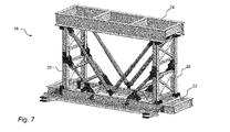
- FIG. 7 shows a sub-module 16 according to the invention in a perspective side view. Not all reference numerals used in the preceding figures are for illustration in FIG Fig. 7 is repeated, insofar as it is specifically applied to the illustration in Fig. 2 directed.
- the sub-module 16 is symmetrical in order to obtain a necessary width (or depth) such that the side hinged supports 26, 28 are actually a pair of side hinged supports connected by truss or other stiffening elements and thus mechanically strong turn together pair of supports again a lateral, hinged support 26, 28 forms.
- struts 46, 48 and stiffeners 50, 52 are each paired.
- Fig. 7 It can also be seen that the individual segments 34-37 of the supports 26, 28 are directly adjacent to each other, whereby the forces are not passed through the joints 30, 32 or the bolts of the joints 30, 32, but directly into the respective profile elements.
- the hinge 30, 32 of the hinged support 26, 28 is therefore outside a in the unfolded state by the center of gravity of each support segment 34-37 extending line (line of force 64).
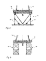
- FIGS. 8 and 9 the position of two aligned substructure modules 16 under a working platform 14 of a drilling rig 10 (FIG. Fig. 1 ), of which in the illustrations still the lower part of the drilling mast 12 can be seen. It is clear from the positions of the feet of the drilling mast 12 that the force introduction points correlated therewith into the substructure are in each case in the region of the position of the lateral supports 26, 28 (side view with a view of the longitudinal side of a substructure module 16 in FIG Fig. 8 ) of two substructure modules 16 as well as in the area of two substructure modules 16 which are positioned parallel to one another at a distance from one another (side view with a view of the transverse side of two substructure modules 16 in FIG Fig. 9 ) lie.
- a sub-module 16 for a mobile land-based drilling rig 10 There are a sub-module 16 for a mobile land-based drilling rig 10, a method for assembling and dismantling such sub-modules 16 and a use of such sub-modular 16 for building a mobile land-based drilling rig 10 and finally a mobile land-boring machine 10 with at least one such sub-module 16 indicated, wherein a Substructure module 16 characterized in that this at least one hinged lateral support 26, 28, in particular two hinged side supports 26, 28, which allows a low height of the substructure module 16 in the folded state and allow a quick and safe installation of a sub-module 16 by unfolding the or each hinged support 26, 28 allowed or allow.
- folding box Due to the folding principle of the at least one lateral support, a designation as "foldable box” is justified for the sub-module 16.
- the folding mechanism of the substructure module 16 (sub-box) is designed so that under certain circumstances in the sub-modules 16 space for equipment, which can remain installed during folding and subsequent transport.
- An advantage of a construction of the hinged side supports 26, 28 with eccentrically arranged joints 30, 32 is on the one hand the better power line and on the other hand the self-locking in the erected state. As described, the latter means that even after loosening the bolts on the transverse struts 46, 48; 50, 52 the sub-module 16 does not collapse. Instead, it always requires an external force that moves the joints 30, 32 over a dead center. It is conceivable for a lever system 70, which at the same time presses the support profiles to the outside when lifting the substructure module 16 by a crane. Thereafter, the raised sub-module 16 could be lowered and the sub-module 16 works by its own weight, especially the weight of the upper base member 24, a.
- a length of the upper base part 24 depends on the dimensions of the working platform 14.
- the height of the substructure modules 16 in the erected state corresponding to the respective blow-out preventer is, for example, 5.40 m.
- the upright Condition vertical segments 34-37 of the supports 26, 28 - support profiles - are connected at the joints so that vertical force components can be passed directly from one profile to the next.
- For horizontal force components by eg wind struts 46, 48 and stiffeners 50, 52 may be provided on the truss principle.
- drilling rig 12 drilling mast 14 platform 16 substructure module 18 Container 20 Blowout preventer 22 (lower) base part / lower part 24 (upper) base part / upper part 26, 28 lateral, foldable support 30, 32 Joint (inner joint) 34, 35, 36, 37 support segment 40, 41, 42, 43 Joint (outer joint) 46, 48 strut 50, 52 stiffening 54, 55 role 56, 58 abutment 60, 62 access point 64 power line 66 first stop point 68 steel cable 70 lever 72 second point of attack
Landscapes
- Engineering & Computer Science (AREA)
- Geology (AREA)
- Life Sciences & Earth Sciences (AREA)
- Mining & Mineral Resources (AREA)
- Environmental & Geological Engineering (AREA)
- Fluid Mechanics (AREA)
- Physics & Mathematics (AREA)
- General Life Sciences & Earth Sciences (AREA)
- Geochemistry & Mineralogy (AREA)
- Mechanical Engineering (AREA)
- Earth Drilling (AREA)
- Casings For Electric Apparatus (AREA)
- Conveying And Assembling Of Building Elements In Situ (AREA)
Abstract
Description
Die Erfindung betrifft einen Unterbau für eine mobile Landbohranlage. Als Unterbau wird dabei eine die Arbeitsbühne mit dem Bohrmast tragende Konstruktion verstanden. Aber auch einzelne Einheiten oder Module eines solchen Unterbaus werden selbst als Unterbau oder einzeln zur Unterscheidung mitunter als Unterbaumodul bezeichnet. Die Erfindung betrifft damit auch solche Unterbaumodule und im Weiteren ein Verfahren zum Auf- und Abbau solcher Unterbauten und Unterbaumodule sowie deren Verwendung zum Errichten einer mobilen Landbohranlage und schließlich eine mobile Landbohranlage mit zumindest einem solchen Unterbau oder solchen Unterbaumodulen.The invention relates to a substructure for a mobile drilling rig. As a substructure while a working platform with the drilling mast supporting construction is understood. But even individual units or modules of such a substructure are sometimes referred to as a substructure or individually for distinction sometimes as a sub-module. The invention thus also relates to such substructure modules and further to a method for assembling and dismantling of such substructures and substructure modules and their use for erecting a mobile land-boring plant and finally a mobile land-boring plant with at least one such substructure or substructure modules.
Unterbauten für mobile Landbohranlagen sind an sich bekannt. Häufig werden als Unterbaumodule ein oder mehrere Container verwendet. Derartige Unterbaumodule werden einzeln oder in Form von zwei oder drei aufeinander gestapelten Containern ("Box-on-Box"-System) paarweise beabstandet nebeneinander aufgestellt und fungieren gleichsam als Stützkonstruktion für eine darauf errichtete und in der Fachterminologie als Rigfloor bezeichnete Arbeitsbühne der Bohranlage, auf der sich der Bohrmast erhebt. Zwischen den Unterbaumodulen wird der Bohrstrang niedergebracht und zwischen den Unterbaumodulen und der Arbeitsbühne bleibt Platz für einen sogenannten Blow-Out-Preventer.Substructures for mobile drilling rigs are known per se. Frequently, one or more containers are used as submodules. Such substructure modules are placed individually or in the form of two or three stacked containers ("box-on-box" system) in pairs next to each other and act as a kind of supporting structure for a built thereon and designated in technical terminology as Rigfloor working platform of the rig which raises the boom. Between the sub-modules of the drill string is drilled and between the sub-modules and the platform remains room for a so-called blow-out preventer.
Die Verwendung von Containern als Unterbaumodule hat den Vorteil, dass übliche Komponenten verwendbar sind und dass der Innenraum der Container zur Aufnahme von Aggregaten der Bohranlage verwendbar ist.The use of containers as substructure modules has the advantage that conventional components are usable and that the interior the container is usable for receiving aggregates of the drilling rig.
Nachteilig bei solchen Containern ist allerdings deren Platz- und Raumbedarf beim Transport, also zum einen die jeweils benötigte Grundfläche und zum anderen deren unveränderliches Volumen und damit deren feste Höhe. Dies ist bei mobilen Landbohranlagen, die oftmals von einem Einsatzort zu einem anderen Einsatzort verbracht werden müssen, ungünstig, weil in erheblichem Umfang Transportmittel, nämlich Schwerlastauflieger oder dergleichen, mit ausreichenden Dimensionen benötigt werden. Entweder werden eine Mehrzahl solcher Schwerlastauflieger mit entsprechenden Zugmaschinen oder ähnliche Transportmittel benötigt oder der Transport wird mehrfach mit wenigen Schwerlastaufliegern durchgeführt, wodurch sich die Dauer des Transports erhöht. Beides ist kostenintensiv.The disadvantage of such containers, however, is their space and space requirements during transport, so on the one hand, the required base area and on the other hand, their constant volume and thus their fixed height. This is unfavorable in mobile land-based drilling rigs, which often have to be moved from one job site to another jobsite, because a significant amount of means of transportation, namely heavy duty trailers or the like, of sufficient dimensions are needed. Either a plurality of such heavy duty semi-trailers with appropriate tractors or similar means of transport are needed or the transport is carried out several times with a few heavy duty semi-trailers, thereby increasing the duration of the transport. Both are costly.
Von besonderer Bedeutung ist also das einfache Transportieren der Bohranlage und ihrer Einzelteile, wobei für Länder mit strengen Transportregularien sämtliche Baugruppen dort jeweils geltenden Transportmaßen genügen müssen, für die entsprechend nationaler Bestimmungen keine Sondergenehmigung notwendig ist, denn der Erhalt solcher Genehmigungen ist stets zeit- und kostenaufwendig.Of particular importance is the simple transport of the drilling rig and its parts, for countries with strict transport regulations all assemblies must comply there applicable transport dimensions for the corresponding national provisions no special permission is necessary, because the receipt of such permits is always time and cost consuming ,
Als mobile Landbohranlagen sind Typen bekannt, die je nach Umgebung in etwa vierzehn Tagen transportiert und aufgebaut werden können. Wenn keine Beschränkungen im Hinblick auf Transportbreiten und Transporthöhen zu beachten sind, zum Beispiel in der Wüste, dann kann durch vormontierte Baugruppen die Aufbauzeit auf ca. sieben Tage reduziert werden. Besondere Anlagentypen sollen - abhängig von der Größe der Anlage - in einem Zeitraum von wenigen Stunden bis zu drei Tagen betriebsbereit sein.Mobile land-boring machines are types that can be transported and set up in a fortnight, depending on the environment. If no restrictions with regard to transport widths and transport heights are to be observed, for example in the desert, preassembled assemblies can reduce the construction time to approx. Seven days. Special plant types should be operational within a period of a few hours to three days, depending on the size of the plant.
Durch eine Möglichkeit eines schnellen und einfachen Transports einer Bohranlage zwischen zwei Bohrplätzen besteht für einen Betreiber der jeweiligen Bohranlage demnach die Möglichkeit für eine erhebliche Kostenersparnis. Allerdings müssen auch Mehrkosten für die meist höhere technische Komplexität von Bohranlagen mit leichter transportierbaren Komponenten berücksichtigt werden.By a possibility of a quick and easy transport of a drilling rig between two drilling sites, there is the possibility for a operator of the respective drilling rig for a significant cost savings. However, additional costs for the usually higher technical complexity of drilling rigs with easily transportable components must also be taken into account.
Im Hinblick auf diese Problematik sind Unterbaumodule konstruiert worden, die zwischen einem unteren und einem oberen Basisteil zum Beispiel schwenkbare Stützen oder eine Scherenhubmechanik aufweisen. Unterbaumodule mit schwenkbaren Stützen oder einer Scherenhubmechanik haben den Vorteil, dass deren Höhe für Transportzwecke reduziert werden kann. Zwei oder mehr Unterbaumodule können dann aufeinander liegend auf einem Schwerlastauflieger oder dergleichen transportiert werden. Dadurch verringert sich die Anzahl der erforderlichen Transportvorgänge, so dass die Dauer des Transports der Bohranlage insgesamt und aller davon umfasster Komponenten und Aggregate reduziert wird.In view of this problem, substructure modules have been constructed which have, for example, pivotable supports or a scissor lift mechanism between a lower and an upper base part. Substructure modules with swiveling supports or a scissor lift mechanism have the advantage that their height can be reduced for transport purposes. Two or more sub-modules may then be transported one upon the other on a heavy-duty trailer or the like. This reduces the number of transport operations required, thus reducing the overall duration of the transport of the rig and all components and aggregates thereof.
Bei solchen Unterbaumodulen sind das untere und obere Basisteil als Stahlprofile ausgeführt und das untere Basisteil überträgt die Kräfte in den Boden, insbesondere in ein Fundament, während das obere Basisteil als Auflager für ein weiteres Unterbaumodul oder für die Arbeitsbühne fungiert. Im Folgenden werden das untere und das obere Basisteil eines Unterbaumoduls für eine mobile Landbohranlage mitunter auch nur kurz als Unterteil bzw. Oberteil des Unterbaumoduls und das Unterbaumodul selbst als Box bezeichnet.In such Unterbaumodulen the lower and upper base part are designed as steel profiles and the lower base part transmits the forces in the ground, in particular in a foundation, while the upper base part acts as a support for another sub-module or for the working platform. Hereinafter, the lower and the upper base part of a sub-module for a mobile drilling rig are sometimes referred to as a lower part or upper part of the sub-module and the sub-module itself as a box.
Das Errichten bekannter Unterbaumodule ist jedoch aufwendig, weil zum Beispiel bei Unterbaumodulen mit schwenkbaren Stützen einerseits deren Oberteile angehoben werden müssen und während der vertikalen Bewegungsrichtung beim Anheben noch eine translatorische Bewegung zum Verschwenken des Oberteils erforderlich ist. Bekannte Unterbaumodule mit einer Scherenhubmechanik können mit einer einfachen Bewegung beim Anheben des Oberteils errichtet werden, allerdings lässt die Scherenhubmechanik in dem durch das Unterbaumodul aufgespannten Volumen nur wenig Raum, um dort Aggregate der Bohranlage oder dergleichen zu platzieren. Für beide bekannten Unterbaumodule gilt zudem, dass das notwendige Fixieren der Scherenhubmechanik oder der schwenkbaren Stützen manuell erfolgt und damit nicht frei von Verletzungsgefahren für das damit befasste Personal ist.However, the construction of known substructure modules is complicated, because, for example, in substructure modules with pivotal supports on the one hand the upper parts must be raised and during the vertical direction of movement during lifting nor a translational movement for pivoting the upper part is required. Known substructure modules with a scissor lift mechanism can be erected with a simple movement when lifting the upper part, but the scissor lift mechanism in the volume spanned by the substructure module leaves only little space to place aggregates of the drilling rig or the like there. For both known substructure modules also applies that the necessary fixing of the scissor lift mechanism or the pivotal supports is done manually and thus is not free of injury to personnel concerned.
Beispiele für bekannte Unterbaumodule finden sich in der
Eine Aufgabe der vorliegenden Erfindung besteht entsprechend darin, eine alternative Ausführungsform eines solchen Unterbaumoduls anzugeben, insbesondere ein solches Unterbaumodul, das sich leicht und mit herkömmlichen Mitteln transportieren und errichten lässt und zudem noch Platz in dem durch das aufgerichtete Unterbaumodul definierten Volumen für Aggregate der Bohranlage lässt.Accordingly, it is an object of the present invention to provide an alternative embodiment of such a substructure module, in particular such a substructure module which can be easily and conventionally transported and erected and, in addition, space in which it is erected Sub-module leaves defined volume for aggregates of the drilling rig.
Die oben genannte Aufgabe wird erfindungsgemäß mit einem Unterbaumodul für eine mobile Landbohranlage mit den Merkmalen des Anspruchs 1 gelöst, wobei das Unterbaumodul ein unteres und ein oberes Basisteil umfasst und wobei sich zwischen dem unterem und dem oberem Basisteil - dem Unterteil und dem Oberteil des Unterbaumoduls - zumindest eine seitliche, klappbare Stütze befindet.The above object is achieved according to the invention with a sub-module for a mobile drilling rig having the features of claim 1, wherein the sub-module comprises a lower and an upper base part and wherein between the lower and the upper base - the lower part and the upper part of the sub-module - at least one side, hinged support is located.
Die oder jede klappbare Stütze weist bevorzugt in der Mitte ein Gelenk auf. Ein solches, in Bezug auf die Längserstreckung der Stütze mittiges Gelenk erlaubt regelmäßige Belastungsverhältnisse und im Vergleich zu genau einem oben oder unten von der Mitte zwischen den Endpunkten der Stütze angeordneten Gelenk eine parallele Endposition beider an das Gelenk angrenzenden Stützensegmente im eingeklappten Zustand. Dies führt zu einer Minimierung der Höhe des Unterbaumoduls im zusammengeklappten Zustand. Das die Klappbarkeit der Stütze ermöglichende Gelenk wird mit Hinblick auf dessen Position entlang der Längserstreckung einer aufgeklappten Stütze als inneres Gelenk bezeichnet.The or each hinged support preferably has a hinge in the middle. Such a center joint in relation to the longitudinal extent of the support allows regular loading conditions and compared to exactly one up or down from the center between the end points of the support arranged joint a parallel end position of both adjoining the joint support segments in the folded state. This leads to a minimization of the height of the sub-module in the collapsed state. The joint which enables the foldability of the support is referred to as an inner joint with regard to its position along the longitudinal extent of an unfolded support.
Indem die oder jede klappbare Stütze an einem Ende gelenkig mit dem unteren Basisteil und am anderen Ende gelenkig mit dem oberen Basisteil verbunden ist, erfolgt das Ausklappen der oder jeder klappbaren Stütze zwangsgeführt mit dem Anheben des oberen Basisteils. Aufgrund der gelenkigen Anbindung sowohl an das obere wie an das untere Basisteil ist ein Eingriff eines Monteurs nicht oder allenfalls bei einer späteren Fixierung des aufgeklappten Unterbaumoduls erforderlich. Die zur gelenkigen Anbindung einer klappbaren Stütze an das untere und obere Basisteil wirksamen Gelenke werden zur Unterscheidung von dem oben beschriebenen inneren Gelenk als äußere Gelenke bezeichnet.By pivotally connecting the or each hinged support at one end to the lower base part and at the other end to the upper base part, the folding out of the or each hinged support is forcibly performed with the lifting of the upper base part. Due to the articulated connection both to the upper and to the lower base part, an intervention of a fitter is not required or at most in a later fixation of the unfolded substructure module. The hinged connection of a hinged support to the lower and upper base part Effective joints are referred to as different from the inner joint described above as outer joints.
Indem das Unterbaumodul an einer am oberen Basisteil angelenkten Seite der oder jeder Stütze mittig eine erste, innere Anschlagsstelle für Hebegeschirr und/oder am Ende eines nach außen gewandten Hebels eine zweite, äußere Anschlagsstelle für Hebegeschirr aufweist, ist eine Möglichkeit für ein besonders einfaches Aufstellen und/oder Zusammenklappen des Unterbaus geschaffen (die erste Anschlagsstelle kann auch direkt am oberen Basisteil gebildet sein). Die beiden Anschlagsstellen für Hebegeschirr - im Folgenden mitunter auch nur kurz als innere oder äußere Hebepunkte bezeichnet - ermöglichen ein selbsttätiges Aufstellen und Zusammenklappen der klappbaren Stützen und damit ein selbsttätiges Aufbauen und Abbauen des Unterbaumoduls selbst. Eine einzelne derartige Anschlagsstelle ermöglicht entsprechend zumindest ein selbsttätiges Aufstellen oder Zusammenklappen der klappbaren Stützen und des Unterbaus.By the sub-module on a hinged to the upper base part of the or each support center a first, inner stop point for lifting harness and / or at the end of an outwardly facing lever has a second, outer stop point for lifting harness, is a possibility for a particularly simple installation and / or folding the substructure created (the first stop position can also be formed directly on the upper base part). The two stop points for lifting equipment - hereinafter also sometimes referred to as inner or outer lifting points - allow an automatic setting up and folding the hinged supports and thus an automatic construction and dismantling of the substructure module itself. A single such attack point allows at least one automatic installation or Folding the hinged supports and substructure.
Üblicherweise ist dabei vorgesehen, dass das Unterbaumodul jeweils seitlich zwei gleichartige klappbare Stützen aufweist und dass jede klappbare Stütze diese Hebepunkte aufweist. Wenn an beiden seitlichen Stützen die inneren Hebepunkte verwendet werden, um das Unterbaumodul mit zum Beispiel einem Kran aufzubauen, lässt sich mit Verwendung dieser inneren Hebepunkte das obere Basisteil anheben und aufgrund des Gewichts des unteren Basisteils ergibt sich ein Aufklappen der seitlichen Stützen. Wenn die beiden Stützensegmente eine senkrechte Ausrichtung eingenommen haben, ergibt sich eine stabile oder stabilisierbare Konfiguration der aufklappbaren Stütze, insbesondere dann, wenn bei Stützen mit einem außermittig angeordneten Gelenk (siehe unten) die beiden an dem Gelenk oder den Gelenken einander gegenüberliegenden Stirnflächen der Stützensegmente in Kontakt kommen, und das Unterbaumodul kann am Aufstellungsort abgesetzt werden. Die Konfiguration ist speziell bei Stützen mit einem außermittigen Gelenk selbsthemmend und die Gewichtskraft sichert die Position/Konfiguration der aufgeklappten seitlichen Stützen. Optional erfolgt dann eine Fixierung der aufgeklappten seitlichen Stützen. Wenn das Unterbaumodul wieder abgebaut werden soll, werden die äußeren Hebepunkte verwendet. Der Hebel, an dessen freiem Ende sich jeweils einer der äußeren Hebepunkte befindet, bewirkt, wenn das Unterbaumodul an den äußeren Hebepunkten mit zum Beispiel einem Kran angehoben wird, dass die die äußeren Hebepunkte aufweisenden oberen Stützensegmente verschwenkt werden. Wenn das obere Basisteil danach abgesenkt wird, ergibt sich ein Einklappen der seitlichen klappbaren Stützen. Das obere Basisteil kann dann weiter abgesenkt werden, bis dieses entweder auf einzelnen Abschnitten der eingeklappten Stützen oder dem unteren Basisteil zu liegen kommt. In dieser Konfiguration kann das Unterbaumodul fixiert werden, zum Beispiel indem Bolzen in die Augen von am unteren und oberen Basisteil gebildete oder angeformte Laschen eingeführt werden. Jetzt kann das gesamte Unterbaumodul, ggf. mit einzelnen oder mehreren darin befindlichen Aggregaten der Bohranlage oder dergleichen, wieder mit zum Beispiel einem Kran angehoben werden und die zusammengeklappte Konfiguration bleibt erhalten. Das zusammengeklappte Unterbaumodul kann auf einem Transportmittel, zum Beispiel einem Schwerlastauflieger, abgelegt werden. Dieses aufgrund des Anhebens des Unterbaumoduls an äußeren Hebepunkten bewirkte Verschwenken der oberen Stützensegmente ergibt sich auch bei Stützen mit einem außermittig angeordneten inneren Gelenk. Hier führt das Verschwenken der oberen Stützensegmente dazu, dass die stabile, selbsthemmende Konfiguration der aufgeklappten Stützen aufgehoben wird und die vorher aufeinander liegenden Stirnflächen außer Eingriff kommen. Dann kann das obere Basisteil abgesenkt werden und es ergibt sich das beschriebene Einklappen der seitlichen klappbaren Stützen. Das obere Basisteil kann dann weiter abgesenkt werden, bis dieses entweder auf einzelnen Abschnitten der eingeklappten Stützen oder dem unteren Basisteil zu liegen kommt. Dann ist die oben bereits beschriebene zusammengeklappte Konfiguration erreicht und das oben Gesagte gilt entsprechend.Usually, it is provided that the sub-module each side has two similar folding supports and that each hinged support has these lifting points. If the inner lifting points are used on both lateral supports to build the sub-module with, for example, a crane, using these inner lifting points, the upper base part can be lifted and, due to the weight of the lower base part, unfolding of the lateral supports. When the two support segments have become vertically aligned, a stable or stabilizable configuration of the hinged support will result, particularly if, in supports with an off-center hinge (see below), the two are opposite one another at the hinge or hinges Face surfaces of the support segments come into contact, and the sub-module can be discontinued at the site. The configuration is self-locking, especially for supports with an off-center hinge, and the weight ensures the position / configuration of the unfolded side supports. Optionally, then a fixing of the unfolded lateral supports. If the sub-module is to be dismantled, the outer lifting points are used. The lever, at the free end of each of which is located one of the outer lifting points, causes when the sub-module is raised at the outer lifting points with, for example, a crane that the outer lifting points having upper support segments are pivoted. When the upper base part is lowered thereafter, a collapse of the lateral hinged supports results. The upper base part can then be further lowered until it comes either to lie on individual sections of the folded-up supports or the lower base part. In this configuration, the sub-module may be fixed, for example, by inserting bolts into the eyes of tabs formed or molded onto the lower and upper base members. Now, the entire sub-module, possibly with individual or more therein aggregates of the drilling rig or the like, be raised again with, for example, a crane and the collapsed configuration is maintained. The collapsed sub-module can be stored on a means of transport, for example a heavy-duty trailer. This caused by the lifting of the substructure module at outer lifting points pivoting of the upper support segments also results in columns with an eccentrically arranged inner joint. Here, the pivoting of the upper support segments leads to the stable, self-locking configuration of the unfolded supports is canceled and the previously superimposed faces except Intervention come. Then, the upper base part can be lowered and it results in the described folding the side hinged supports. The upper base part can then be further lowered until it comes either to lie on individual sections of the folded-up supports or the lower base part. Then, the collapsed configuration already described above is achieved and the above applies accordingly.
Der Vorteil eines solchen Unterbaumoduls - einer solchen Box - besteht darin, dass dieses bzw. diese leicht errichtet werden kann, denn es reicht aus, dessen bzw. deren Oberteil anzuheben, bis die oder jede seitliche Stütze ausklappt und so eine Höhe des Unterbaumoduls in einer Betriebskonfiguration festlegt. Aufgrund zumindest einer klappbaren Stütze, zum Beispiel in Verbindung mit einer Scherenhubmechanik, oder zweier jeweils seitlich angeordneter klappbarer Stützen lässt sich die Höhe des Unterbaumoduls durch Einklappen der oder jeder entsprechenden Stütze deutlich reduzieren, so dass sich eine für den Transport günstige Höhe ergibt.The advantage of such a sub-module - such a box - is that this or this can be easily erected, because it is sufficient to raise its or its upper part until the or each side support folds out and so a height of the sub-module in one Determines operating configuration. Due to at least one hinged support, for example in conjunction with a scissor lift mechanism, or two each laterally arranged hinged supports, the height of the substructure module can be significantly reduced by folding the or each corresponding support, so that there is a favorable for transport height.
Vorteilhafte Ausgestaltungen der Erfindung sind Gegenstand der Unteransprüche. Dabei verwendete Rückbeziehungen weisen auf die weitere Ausbildung des Gegenstandes des Hauptanspruches durch die Merkmale des jeweiligen Unteranspruches hin. Sie sind nicht als ein Verzicht auf die Erzielung eines selbständigen, gegenständlichen Schutzes für die Merkmalskombinationen der rückbezogenen Unteransprüche zu verstehen. Des Weiteren ist im Hinblick auf eine Auslegung der Ansprüche bei einer näheren Konkretisierung eines Merkmals in einem nachgeordneten Anspruch davon auszugehen, dass eine derartige Beschränkung in den jeweils vorangehenden Ansprüchen nicht vorhanden ist.Advantageous embodiments of the invention are the subject of the dependent claims. Here used backlinks indicate the further development of the subject matter of the main claim by the features of the respective subclaim. They should not be construed as a waiver of obtaining independent, objective protection for the feature combinations of the dependent claims. Furthermore, with a view to an interpretation of the claims in a closer specification of a feature in a subordinate claim, it is to be assumed that such a restriction does not exist in the respective preceding claims.
Wenn das innere Gelenk ein Zusammenklappen der oder jeder klappbaren Stütze weg vom Innenraum des Unterbaumoduls ermöglicht, bleibt bei einem zusammengeklappten Unterbaumodul zwischen dessen Unter- und Oberteil ein freier Raum, der für Aggregate der Bohranlage oder dergleichen genutzt werden kann, so dass solche Einheiten auch bei einem Transport des Unterbaumoduls im Unterbaumodul verbleiben oder im Unterbaumodul und mit dem Unterbaumodul verbunden bleiben können. Auch dies spart Zeit und Aufwand beim Transport und Einheiten, die in einem Unterbaumodul verbleiben, sind beim Transport sogar noch durch das Unterbaumodul geschützt. Alternativ ist grundsätzlich auch ein Zusammenklappen der Stützen in Richtung auf den Innenraum des Unterbaumoduls möglich. Dies kommt dann in Betracht, wenn beim Transport keine Aggregate im Unterbaumodul oder nur Aggregate, deren Platzbedarf den bei nach innen eingeklappten Stützen verbleibenden Platz nicht überschreitet, verbleiben sollen.When the inner joint allows folding of the or each hinged support away from the interior of the sub-module, remains at a collapsed sub-module between the lower and upper part of a free space that can be used for aggregates of the rig or the like, so that such units also in remain a transport of the sub-module in the sub-module or remain connected in the sub-module and the sub-module. This also saves time and effort during transport and units that remain in a sub-module are even protected by the sub-module during transport. Alternatively, a collapse of the supports in the direction of the interior of the substructure module is basically possible. This comes into consideration if during transport no aggregates in the sub-module or only aggregates whose space requirement does not exceed the remaining inwardly collapsed columns space, should remain.
Bei einer besonderen Ausführungsform des Unterbaumoduls ist vorgesehen, dass ein inneres Gelenk oder das innere Gelenk der oder jeder klappbaren Stütze außerhalb einer im aufgeklappten Zustand durch den Schwerpunkt jedes Stützensegments verlaufenden Linie (Kraftlinie) liegt und einen Kontaktstoß der einzelnen Stützenteile zueinander ermöglicht. Vertikale Kraftanteile werden folglich vom oberen Basisteil und dem oberhalb des inneren Gelenks angreifenden Stützensegment direkt in das unterhalb des inneren Gelenks angreifende Stützensegment und von dort in das untere Basisteil geleitet. Ein Gelenkbolzen oder dergleichen im inneren Gelenk ist frei oder zumindest im Wesentlichen frei von Belastungen. Diese Anordnung des inneren Gelenks außerhalb der Kraftlinie wird auch als außermittige oder exzentrische Anordnung bezeichnet.In a particular embodiment of the sub-module, it is provided that an inner joint or the inner joint of the or each foldable support is outside a line (force line) extending in the unfolded state through the center of gravity of each column segment and allows contact of the individual support members to each other. Consequently, vertical force components are directed from the upper base part and the support segment acting above the inner joint directly into the support segment engaging below the inner joint and from there into the lower base part. A hinge pin or the like in the inner joint is free or at least substantially free of stress. This arrangement of the inner joint outside the line of force is also referred to as off-center or eccentric arrangement.
Bei einer besonderen Ausführungsform ist bei einem Unterbaumodul, dessen klappbare Stützen mit dem oberen und dem unteren Basisteil gelenkig verbunden sind, vorgesehen, dass jedes äußere Gelenk oder die äußeren Gelenke und das oder jedes innere Gelenk außerhalb einer im aufgeklappten Zustand durch den Schwerpunkt jedes Stützensegments verlaufenden Linie (Kraftlinie) liegt bzw. liegen. Dann sind alle Gelenkbolzen oder dergleichen frei oder im Wesentlichen frei von Belastungen aufgrund einer Krafteinleitung durch die bei der Verwendung des Unterbaumoduls aufgenommenen Gewichte oder dynamischen Belastungen, etwa Windlasten.In a particular embodiment, in a sub-module whose hinged supports are hingedly connected to the upper and lower base members, each outer hinge or hinges and the or each inner hinge are disposed outside of an unfolded state through the center of gravity of each column segment Line (force line) lies or lie. Then, all of the hinge pins or the like are free or substantially free of stress due to force application by the weights received during use of the sub-module or dynamic loads, such as wind loads.
Ein Vorteil des hier vorgeschlagenen Unterbaumoduls und seiner Ausgestaltungen ist, dass auf dieses bzw. dessen klappbare Stützen beim Aufrichten keine Antriebskraft wirkt oder wirken muss und dass sich die klappbaren Stützen während des Prozesses des Aufstellens nur oder zumindest im Wesentlichen unter Gravitationseinfluss aufrichten. Die aufgerichteten Stützen können dann zusätzlich durch Verstrebungen in ihrer vertikalen Ausrichtung fixiert werden. Damit lässt sich das Aufrichten eines Unterbaumoduls zum Beispiel mit einem Transportkran bewerkstelligen. Alternativ ist ein Auf- und Abbauen des Unterbaumoduls auch mit Hilfe von zum Beispiel hydraulisch teleskopierbaren Elementen möglich.An advantage of the substructure module and its embodiments proposed here is that no drive force acts or has to act on this or its hinged supports when erecting, and that the folding supports only or at least substantially raise themselves under the influence of gravity during the process of setting up. The uprights can then be additionally fixed by struts in their vertical orientation. This can be the erection of a sub-module, for example, with a transport crane accomplish. Alternatively, assembly and disassembly of the substructure module is also possible with the aid of, for example, hydraulically telescopic elements.
Wenn das Unterbaumodul am Kran hängt, können Arretierungen, welche die faltbaren oder klappbaren Stützen in einer gefalteten / geklappten Konfiguration halten, gelöst werden und das untere Profil (Unterteil) des Unterbaumoduls "fällt" quasi nach unten, bis die Stützen ausgeklappt sind und diese eine vertikale Orientierung erreicht haben. Selbstverständlich ist das Szenario des "Fallens" nur ein Beispiel und in der Praxis wird eher die Situation zum Tragen kommen, dass das noch zusammengelegte Unterbaumodul mit einem Kran oder einem sonstigen Transportwerkzeug (zum Beispiel einem Gabelstapler) zum Aufstellungsort verbracht wird. Sodann werden eventuelle Arretierungen, welche die faltbaren oder klappbaren Stützen in einer gefalteten / geklappten Konfiguration halten, gelöst. Jetzt kann das obere Profil (Oberteil) des Unterbaumoduls (mit einem Kran, einem Gabelstapler oder dergleichen) angehoben werden, bis die Stützen ausgeklappt sind. Speziell wenn die Stützen mit außermittigen oder exzentrischen Gelenken realisiert sind, ergibt sich bereits mit dem hier beschriebenen bloßen Aufrichten des Unterbaumoduls eine zumindest anfängliche Standfähigkeit. Diese kann noch verbessert werden, wenn die Stützen nach dem Aufrichten des Unterbaumoduls im ausgeklappten Zustand fixiert werden, zum Beispiel durch Verbolzen, insbesondere beidseitiges Verbolzen. Zusätzlich oder alternativ zu einer solchen Fixierung kommt in Betracht, die ausgeklappten Stützen durch Streben und/oder Versteifungen in der ausgeklappten Konfiguration zu fixieren und damit die strukturelle Steifigkeit des ausgeklappten Unterbaumoduls insgesamt zu erhöhen. Als Streben oder Versteifungen kommen vorgefertigte Konstruktionsteile in Betracht, die hinsichtlich ihrer Ausmaße, insbesondere hinsichtlich ihrer Länge, auf die vorbekannten Abstände zwischen den in Frage kommenden Anschlagsstellen abgestimmt sind. Zusätzlich oder alternativ kommen als Streben oder Versteifungen auch längenveränderliche, insbesondere teleskopierbare Elemente in Betracht. Die Längenanpassung kann dabei durch eine geeignete Montage einer zum Beispiel aus zwei miteinander kombinierbaren Teilen zusammengesetzten und als Strebe fungierenden Versteifung erfolgen. Ansonsten lässt sich eine Längenanpassung auch unter Verwendung eines Gewindes erreichen. Die Verwendung längenveränderlicher, insbesondere teleskopierbarer Elemente hat den Vorteil, dass diese auch beim Einklappen des Unterbaumoduls nicht notwendig demontiert werden müssen. Als längenveränderliche Elemente kommen zum Beispiel auch Hydraulikstempel oder dergleichen in Betracht.When the sub-module hangs from the crane, detents holding the foldable or foldable supports in a folded / folded configuration can be released and the bottom profile of the sub-module virtually "drops" until the supports are unfolded and one have reached vertical orientation. Of course, the scenario of "falling" is just one example, and in practice the situation will be more likely to come to fruition, with the submodule still merging with a crane or other transport tool (for example, a forklift) is brought to the site. Then, any detents that hold the foldable or foldable supports in a folded / folded configuration are released. Now, the upper profile (top) of the sub-module (with a crane, a forklift or the like) can be raised until the supports are unfolded. Especially when the supports are realized with off-center or eccentric joints, already with the mere erection of the substructure module described here results in an at least initial stability. This can be further improved if the supports are fixed after erecting the substructure module in the unfolded state, for example by bolting, in particular bilateral bolting. In addition or as an alternative to such a fixation, it is possible to fix the unfolded supports by struts and / or stiffeners in the unfolded configuration and thus to increase the overall structural rigidity of the unfolded substructure module. As struts or stiffeners come prefabricated construction parts into consideration, which are matched in terms of their dimensions, in particular with regard to their length to the known distances between the candidate stop points. Additionally or alternatively come as struts or stiffeners and variable-length, in particular telescoping elements into consideration. The length adjustment can be done by a suitable assembly of a composite, for example, two parts can be combined together and acting as a strut stiffening. Otherwise, a length adjustment can also be achieved by using a thread. The use of variable-length, in particular telescoping elements has the advantage that they do not necessarily have to be dismantled when folding the sub-module. As variable-length Elements come for example also hydraulic ram or the like into consideration.
Insgesamt betrifft die Erfindung damit auch ein Verfahren zum Aufrichten und/oder Abbauen eines Unterbaumoduls wie hier und im Folgenden beschrieben, einen Unterbau für eine mobile Bohranlage mit einem oder mehreren derartigen Unterbaumodulen, eine mobile Bohranlage mit einem oder mehreren derartigen Unterbaumodulen sowie eine Verwendung eines oder mehrerer solcher Unterbaumodule in einer mobilen Bohranlage.Overall, the invention thus also relates to a method for erecting and / or dismantling a substructure module as described here and below, a substructure for a mobile drilling rig with one or more such substructure modules, a mobile drilling rig with one or more such substructure modules and a use of or several such sub-modules in a mobile drilling rig.
Nachfolgend wird ein Ausführungsbeispiel der Erfindung anhand der Zeichnung näher erläutert. Einander entsprechende Gegenstände oder Elemente sind in allen Figuren mit den gleichen Bezugszeichen versehen.An embodiment of the invention will be explained in more detail with reference to the drawing. Corresponding objects or elements are provided in all figures with the same reference numerals.
Das oder jedes Ausführungsbeispiel ist nicht als Einschränkung der Erfindung zu verstehen. Vielmehr sind im Rahmen der vorliegenden Offenbarung auch Abänderungen und Modifikationen möglich, die zum Beispiel durch Kombination oder Abwandlung von einzelnen in Verbindung mit den im allgemeinen oder speziellen Beschreibungsteil beschriebenen sowie in den Ansprüchen und/oder der Zeichnung enthaltenen Merkmalen oder Verfahrensschritten für den Fachmann im Hinblick auf die Lösung der Aufgabe entnehmbar sind und durch kombinierbare Merkmale zu einem neuen Gegenstand oder zu neuen Verfahrensschritten bzw. Verfahrensschrittfolgen führen.The or each embodiment is not to be understood as limiting the invention. Rather, in the context of the present disclosure, modifications and modifications are possible, for example, by combining or modifying individual in combination with the described in the general or specific description part and in the claims and / or the drawings features or method steps in the art can be removed to the solution of the problem and lead by combinable features to a new object or to new process steps or process steps.
Es zeigen
- Fig. 1
- eine schematisch vereinfachte Darstellung einzelner Teile einer mobilen Landbohranlage,
- Fig. 2
- eine Seitenansicht eines Unterbaumoduls für eine mobile Landbohranlage,
- Fig. 3
- Momentaufnahmen bei Abbauen (Einklappen) eines Unterbaumoduls gemäß
Fig. 2 , - Fig. 4
- eine Darstellung einer klappbaren, seitlichen Stütze eines Unterbaumoduls,
- Fig. 5
- Momentaufnahmen bei Aufbauen (Aufrichten, Ausklappen) eines Unterbaumoduls gemäß
Fig. 2 , - Fig. 6
- Anschlagsstellen für Hebegeschirr zum Auf- und Abbauen eines Unterbaumoduls,
- Fig. 7
- eine perspektivische Ansicht des Unterbaumoduls aus
Fig. 2 sowie - Fig. 8
- und
- Fig. 9
- unterschiedliche Ansichten eines Unterbaus einer mobilen Landbohranlage gemäß
Fig. 1 mit Unterbaumodulen entsprechend der hier vorgelegten Beschreibung.
- Fig. 1
- a simplified schematic representation of individual parts of a mobile drilling rig,
- Fig. 2
- a side view of a sub-module for a mobile land rig,
- Fig. 3
- Snapshots when dismantling (collapsing) a substructure module according to
Fig. 2 . - Fig. 4
- a representation of a hinged, lateral support of a sub-module,
- Fig. 5
- Snapshots when building (erecting, unfolding) a sub-module according to
Fig. 2 . - Fig. 6
- Stop points for lifting harness for assembling and dismantling a substructure module,
- Fig. 7
- a perspective view of the sub-module
Fig. 2 such as - Fig. 8
- and
- Fig. 9
- different views of a substructure of a mobile land rig according to
Fig. 1 with sub-modules according to the description presented here.
Die notwendige Höhe der Arbeitsbühne 14 wird durch einen unterhalb der Arbeitsbühne 14 und zwischen zwei als Pfeiler fungierenden Unterbaumodulen 16 oder zwei als Pfeiler fungierenden Kombinationen mehrerer Unterbaumodule 16 platzierten Blow-Out-Preventer 20 bestimmt.The necessary height of the working
Das Unterbaumodul 16 umfasst ein unteres Basisteil 22 (Unterteil 22), ein oberes Basisteil 24 (Oberteil 24) und bei der dargestellten Ausführungsform zwei seitliche, klappbare Stützen 26, 28. Die seitlichen, klappbaren Stützen 26, 28 (im Folgenden mitunter auch nur kurz als Stützen 26, 28 bezeichnet) weisen in der Mitte jeweils ein Gelenk 30, 32 auf. Das Gelenk 30, 32 verbindet jeweils ein unteres und ein oberes Stützensegment 34, 35; 36, 37. Jedes Stützensegment 34-37 ist seinerseits an der vom Gelenk 30, 32 abgewandten Seite gelenkig mit dem Unter- und Oberteil 22, 24 verbunden. Zur Unterscheidung der Gelenke wird das oder jedes jeweils zwei Stützensegmente 34-37 verbindende Gelenk 30, 32 als inneres Gelenk 30, 32 bezeichnet und entsprechend werden diejenigen Gelenke 40, 41; 42, 43, die eine gelenkige Anbindung der Stützensegmente 34-37 an die Basisteile 22, 24 bewirken, als äußere Gelenke 40-43 bezeichnet.The sub-module 16 comprises a lower base part 22 (lower part 22), an upper base part 24 (upper part 24) and, in the illustrated embodiment, two lateral hinged supports 26, 28. The lateral hinged supports 26, 28 (hereinafter sometimes only briefly as supports 26, 28) have in the middle in each case a
Aufgrund der inneren und äußeren Gelenke 30, 32; 40-43 können die beiden seitlichen Stützen 26, 28 nach außen klappen, wodurch sich die Höhe des Unterbaumoduls 16 reduziert. Dies ist in der Darstellung in
Die linke Darstellung in
Zur Fixierung der aufgeklappten Konfiguration des Unterbaumoduls 16 sind Strukturelemente, nämlich bei der dargestellten Ausführungsform Streben 46, 48 und/oder Versteifungen 50, 52, vorgesehen. Die Streben 46, 48 greifen am freien Ende eines langen Schenkels an den inneren Gelenken 30, 32, genauer gesagt an Laschen knapp unterhalb der inneren Gelenke 30, 32, an. Auf der gegenüberliegenden Seite, also am freien Ende eines kurzen Schenkels, sind die Streben 46, 48 am unteren Basisteil 22 auf Rollen 54, 55 geführt. In der in
Die Versteifungen 50, 52 sind hier als teleskopierbare Versteifungen 50, 52 dargestellt. Andere Möglichkeiten zur Längeneinstellung der Versteifungen 50, 52, zum Beispiel ein Gewinde oder eine Kombination von Teleskopierbarkeit und Gewinde, sind ebenfalls denkbar. Die Versteifungen 50, 52 wirken in dem aufgestellten Unterbaumodul 16 wie ein Fachwerk und sind neben den Stützen 26, 28 zur Ableitung von Kräften, speziell von nicht exakt vertikal wirkenden Kräften, wie zum Beispiel Kräften aufgrund einer momentanen Windlast, in das untere Basisteil 22 wirksam. Die Versteifungen 50, 52 sind dauerhaft oder lösbar schwenkbeweglich am unteren Basisteil 22 angelenkt. Zum Anbringen der Versteifungen 50, 52 wird jede Versteifung 50, 52 in Richtung auf einen Anbindungspunkt 60, 62 am oberen Basisteil 24 und im Bereich der am oberen Basisteil 24 angreifenden äußeren Gelenke 41, 43 verschwenkt und auf eine passende Länge eingestellt. Dann kann das noch freie Ende jeder Versteifung 50, 52 lösbar mit dem oberen Basisteil 24 verbunden werden, zum Beispiel durch Verbolzen oder dergleichen.The
Die jeweiligen Strukturelemente, hier also die Streben 46, 48 und Versteifungen 50, 52, lassen sich entweder teleskopieren (Versteifungen 50, 52 - "lange Streben") oder bewegen sich in einen Freiraum zwischen den Segmenten 34-37 der Stütze 26, 28 ("kurze" Streben 46, 48) hinein. Für dieses Verfahren müssen für jede Strebe 46, 48, 50, 52 jeweils zumindest ein Bolzen oder beide Bolzen gelöst werden, mit dem bzw. mit denen diese angeschlagen sind. Es wird davon ausgegangen, dass diese Bolzen ohne Hilfsmittel gelöst werden können.The respective structural elements, in this case the
Bei der in
Die Darstellung in
Bei der in den Figuren dargestellten Situation, bei der auch die äußeren Gelenke 40-43 solche selbsthemmenden Gelenke sind, schneidet die Kraftlinie 64 auch die äußeren Gelenke 40-43 nicht und die äußeren Gelenke 40-43 liegen ebenfalls komplett außerhalb der Kraftlinie 64. Gelenkbolzen oder dergleichen bleiben dabei kraftfrei und die Kraftübertragung erfolgt über die jeweils aufeinander treffenden Stoß- oder Stirnflächen, nämlich für das innere Gelenk 30, 32 über die dort aufeinander treffenden Stirnflächen der jeweiligen Stützensegmente 34, 36; 35, 37, und für die äußeren Gelenke 40, 41; 42, 43 über die Stirn- und Stoßflächen der jeweiligen Stützensegmente 34, 36; 35, 37 sowie des unteren und oberen Basisteils 22, 24.In the situation shown in the figures, in which the outer joints 40-43 are such self-locking joints, the line of
Zum Aufrichten eines Unterbaumoduls 16 mit einem Kran oder dergleichen weist das Unterbaumodul 16 an einer am oberen Basisteil 24 angelenkten Seite der oder jeder klappbaren Stütze 26, 28 mittig eine erste Anschlagsstelle 66 (
Zum Abbauen und Einklappen eines Unterbaumoduls 16 mit einem Kran oder dergleichen weist das Unterbaumodul 16 an einer am oberen Basisteil 24 angelenkten Seite der oder jeder klappbaren Stütze 26, 28 außermittig am Ende eines nach außen gewandten Hebels 70 eine zweite Anschlagsstelle 72 für Hebegeschirr auf. Dadurch, dass die zweite Anschlagsstelle 72 außermittig und auch von einer Längsachse der aufgerichteten Stütze 26, 28 aus gesehen jenseits der Drehachse des jeweiligen äußeren Gelenks 41, 43 liegt, übt eine beim Anheben des Unterbaumoduls 16 mit einem Kran wirkende Zugkraft ein Drehmoment auf das an dem jeweiligen äußeren Gelenk 41, 43 angelenkte Stützensegment 36, 37 aus, so dass dieses mit dem inneren Gelenk 30, 32 nach außen schwenkt. Die im aufgerichteten Zustand des Unterbaumoduls 16 bestehende Selbsthemmung der Gelenke wird also überwunden und die bisher mit dem Kran ausgeübte Zugkraft kann reduziert oder unterbrochen werden, so dass das obere Basisteil 24 absinken kann und sich dabei die Stützen 26, 28 einklappen.For dismantling and folding a
Die Darstellung in
Die Darstellung in
Abschließend zeigen die Darstellungen in
Wesentliche Aspekte der hier vorliegenden Beschreibung lassen sich damit kurz wie folgt zusammenfassen: Es werden ein Unterbaumodul 16 für eine mobile Landbohranlage 10, ein Verfahren zum Auf- und Abbau solcher Unterbaumodule 16 sowie eine Verwendung solcher Unterbaumodule 16 zum Errichten einer mobilen Landbohranlage 10 und schließlich eine mobile Landbohranlage 10 mit zumindest einem solchen Unterbaumodul 16 angegeben, wobei sich ein Unterbaumodul 16 dadurch auszeichnet, dass dieses zumindest eine klappbare, seitliche Stütze 26, 28, insbesondere zwei klappbare seitliche Stützen 26, 28, aufweist, die im eingeklappten Zustand eine geringe Höhe des Unterbaumoduls 16 ermöglicht bzw. ermöglichen und eine schnelle und gefahrlose Errichtung eines Unterbaumoduls 16 durch Ausklappen der oder jeder klappbaren Stütze 26, 28 erlaubt bzw. erlauben. Aufgrund des Klappprinzips der zumindest einen seitlichen Stütze rechtfertigt sich für das Unterbaumodul 16 eine Bezeichnung als "Foldable box". Der Faltmechanismus des Unterbaumoduls 16 (Unterbaubox) ist so gestaltet, dass unter Umständen in den Unterbaumodulen 16 Platz für Equipment ist, welches auch beim Einklappen und beim anschließenden Transport eingebaut bleiben kann.Essential aspects of the present description can thus be briefly summarized as follows: There are a sub-module 16 for a mobile land-based
Ein Vorteil einer Konstruktion der klappbaren, seitlichen Stützen 26, 28 mit exzentrisch angeordneten Gelenken 30, 32 ist zum einen die bessere Kraftleitung und zum anderen die Selbsthemmung im aufgerichteten Zustand. Wie beschrieben bedeutet Letzteres, dass selbst nach dem Lösen der Bolzen an den Querstreben 46, 48; 50, 52 das Unterbaumodul 16 nicht zusammenklappt. Es ist stattdessen immer eine externe Kraft vonnöten, die die Gelenke 30, 32 über einen Totpunkt bewegt. Denkbar ist dafür ein Hebelsystem 70, welches beim Anheben des Unterbaumoduls 16 durch einen Kran gleichzeitig die Stützprofile nach außen drückt. Danach könnte das angehobene Unterbaumodul 16 abgesenkt werden und das Unterbaumodul 16 klappt sich durch sein Eigengewicht, speziell das Eigengewicht des oberen Basisteils 24, ein.An advantage of a construction of the hinged side supports 26, 28 with eccentrically arranged
Eine Länge des oberen Basisteils 24 richtet sich nach den Abmessungen der Arbeitsbühne 14. Die Höhe der Unterbaumodule 16 beträgt im aufgerichteten Zustand entsprechend dem jeweiligen Blow-Out-Preventer zum Beispiel 5,40 m. Die im aufgerichteten Zustand vertikalen Segmente 34-37 der Stützen 26, 28 - Stützprofile - werden an den Gelenkstellen so verbunden, dass vertikale Kraftanteile direkt von einem Profil in das nächste geleitet werden können. Für horizontale Kraftanteile durch z.B. Wind können Streben 46, 48 und Versteifungen 50, 52 nach dem Fachwerkprinzip vorgesehen sein.A length of the
Claims (14)
wobei die oder jede klappbare Stütze (26, 28) in der Mitte ein Gelenk (30, 32) aufweist,
wobei die oder jede klappbare Stütze (26, 28) an einem Ende gelenkig mit dem unteren Basisteil (22) und am anderen Ende gelenkig mit dem oberen Basisteil (24) verbunden ist,
dadurch gekennzeichnet, dass
am oberen Basisteil (24) oder an einer am oberen Basisteil (24) angelenkten Seite der oder jeder Stütze (26, 28) mittig eine erste Anschlagsstelle (66) für Hebegeschirr gebildet ist und
dass an einer am oberen Basisteil (24) angelenkten Seite der oder jeder Stütze (26, 28) außermittig am Ende eines nach außen gewandten Hebels (70) eine zweite Anschlagsstelle (72) für Hebegeschirr gebildet ist.Substructure module (16) for a mobile shore drilling rig (10) with a lower and an upper base part (22, 24) and with at least one, in particular two lateral, hinged supports (26, 28) between the lower and the upper base part (10). 22, 24),
the or each hinged support (26, 28) having a hinge (30, 32) in its center,
the or each hinged support (26, 28) being hinged at one end to the lower base (22) and at the other end hinged to the upper base (24),
characterized in that
on the upper base part (24) or on a side hinged to the upper base part (24) of the or each support (26, 28) is centrally formed a first stop point (66) for lifting harness and
in that on a side hinged to the upper base part (24) of the or each support (26, 28) a second abutment point (72) for lifting harness is formed off-center at the end of an outwardly directed lever (70).
Applications Claiming Priority (2)
| Application Number | Priority Date | Filing Date | Title |
|---|---|---|---|
| DE102012204458 | 2012-03-20 | ||
| DE201210209988 DE102012209988A1 (en) | 2012-03-20 | 2012-06-14 | Sub-module for a mobile drilling rig and method for assembling and dismantling such sub-modules |
Publications (3)
| Publication Number | Publication Date |
|---|---|
| EP2642065A2 true EP2642065A2 (en) | 2013-09-25 |
| EP2642065A3 EP2642065A3 (en) | 2017-11-15 |
| EP2642065B1 EP2642065B1 (en) | 2018-12-19 |
Family
ID=47915454
Family Applications (1)
| Application Number | Title | Priority Date | Filing Date |
|---|---|---|---|
| EP13159320.4A Active EP2642065B1 (en) | 2012-03-20 | 2013-03-15 | Substructure module for a mobile onshore drilling installation and method for constructing and dismantling such substructure modules |
Country Status (2)
| Country | Link |
|---|---|
| EP (1) | EP2642065B1 (en) |
| DE (1) | DE102012209988A1 (en) |
Cited By (3)
| Publication number | Priority date | Publication date | Assignee | Title |
|---|---|---|---|---|
| US9617804B2 (en) | 2014-05-21 | 2017-04-11 | Bauer Deep Drilling Gmbh | Drill rod magazine |
| CN113374411A (en) * | 2021-07-27 | 2021-09-10 | 恒天九五重工有限公司 | Pedal supporting device of rotary drilling rig |
| CN114033303A (en) * | 2021-11-08 | 2022-02-11 | 中铁武汉电气化局集团科工装备有限公司 | Tunnel inner wall drilling equipment |
Families Citing this family (2)
| Publication number | Priority date | Publication date | Assignee | Title |
|---|---|---|---|---|
| DE102013223031A1 (en) | 2013-11-12 | 2015-05-13 | Bentec Gmbh Drilling & Oilfield Systems | Stand for a drilling rig |
| US10323466B2 (en) | 2014-08-11 | 2019-06-18 | Pioneer Energy Services Corp. | Drilling rig and method of use |
Family Cites Families (8)
| Publication number | Priority date | Publication date | Assignee | Title |
|---|---|---|---|---|
| US3807109A (en) * | 1972-10-19 | 1974-04-30 | Moore Corp Lee C | Oil well drilling apparatus |
| SU901502A1 (en) * | 1980-04-02 | 1982-01-30 | За витель .-YlLv- y; i . т-пг- т - Куликов и В. Ф. Полежаев ВСЕСОШЗ ;г.А а | Portal mine drilling rig |
| US4366650A (en) * | 1980-08-04 | 1983-01-04 | Pre Corporation | Support arrangement including base support means and elevatable support means to transport a drawworks and drilling mast supported thereon and for positioning at a drilling location |
| US4489526A (en) * | 1983-03-08 | 1984-12-25 | Skytop Brewster Company | Drill rig elevating floor structure |
| US7357616B2 (en) * | 2003-01-30 | 2008-04-15 | Doyon Drilling, Inc. | Method and apparatus for transporting oil rig |
| US7497052B2 (en) * | 2006-04-17 | 2009-03-03 | Equipment Engineering Company of Liaohe Petroleum Exploration Bureau, CNPC | Scissors type vertical elevated substructure |
| US8556003B2 (en) * | 2009-11-18 | 2013-10-15 | National Oilwell Varco, L.P. | Split sub-basement drill rig |
| US8112946B2 (en) * | 2009-11-23 | 2012-02-14 | Woolslayer Companies, Inc. | Articulating mast |
-
2012
- 2012-06-14 DE DE201210209988 patent/DE102012209988A1/en not_active Withdrawn
-
2013
- 2013-03-15 EP EP13159320.4A patent/EP2642065B1/en active Active
Cited By (3)
| Publication number | Priority date | Publication date | Assignee | Title |
|---|---|---|---|---|
| US9617804B2 (en) | 2014-05-21 | 2017-04-11 | Bauer Deep Drilling Gmbh | Drill rod magazine |
| CN113374411A (en) * | 2021-07-27 | 2021-09-10 | 恒天九五重工有限公司 | Pedal supporting device of rotary drilling rig |
| CN114033303A (en) * | 2021-11-08 | 2022-02-11 | 中铁武汉电气化局集团科工装备有限公司 | Tunnel inner wall drilling equipment |
Also Published As
| Publication number | Publication date |
|---|---|
| EP2642065B1 (en) | 2018-12-19 |
| DE102012209988A1 (en) | 2013-10-10 |
| EP2642065A3 (en) | 2017-11-15 |
Similar Documents
| Publication | Publication Date | Title |
|---|---|---|
| DE60111852T2 (en) | SELF-LIFTING PLATFORM DEVICE | |
| DE60022944T2 (en) | Lifting platform and method climbing on guide rails | |
| EP2642065B1 (en) | Substructure module for a mobile onshore drilling installation and method for constructing and dismantling such substructure modules | |
| DE3641349A1 (en) | Structural support | |
| EP2601349B1 (en) | Track system with support fitting for height-adjustable support of a bearing and guiding rail | |
| EP3381858B1 (en) | Temporary elevator designed from a kit | |
| EP2288770A2 (en) | Device for demolishing constructions | |
| DE3420737A1 (en) | Auxiliary apparatus for vertically adjustable scaffolding | |
| EP3494259A1 (en) | Bridge prop for propping a bridge segment and method for operating bridge props | |
| DE68903372T2 (en) | COLLECTABLE CRANE WITH A BOOM CONSISING OF TWO OR THREE JOINTLY CONNECTED ELEMENTS. | |
| EP4209656B1 (en) | Modular tunnel formwork device | |
| DE10212305A1 (en) | Procedure for erecting of tower for wind power plant from prefabricated elements, involves lifting and mounting elements by assembly unit which is moved by walking support | |
| EP3522314A1 (en) | Protective scaffolding, in particular open air protective scaffolding and method for setting up a protective scaffolding | |
| DE3200939A1 (en) | CEILING TABLES FOR THE CASTING OF CONCRETE CEILINGS | |
| EP2571663B1 (en) | Method and manufacturing system for producing prefabricated parts from mineral-bound building materials | |
| EP4227470A1 (en) | Transportable building | |
| DE4422753A1 (en) | Device for supporting ceiling shuttering | |
| WO2010049326A2 (en) | Maintenance system | |
| DE102010047595A1 (en) | Elevating platform truck for bringing person basket to desired working height of up to multiple of thousand meters during e.g. changing filament lamps, has protection device detachably mounted at basket against fall of person from roof | |
| EP2025859A1 (en) | Deep drilling device and method for mounting a deep drilling device | |
| DE3546036A1 (en) | Building machine | |
| EP4056785B1 (en) | Support device, ceiling support, ceiling formwork system and method for stripping a ceiling formwork panel | |
| DE2157669A1 (en) | PROCEDURE AND DEVICE FOR ASSEMBLING A STRUCTURE, IN PARTICULAR A GENTLE CRANE | |
| EP3483430A1 (en) | Method and mounting device for mounting a tower section, method for assembling a tower for a wind power plant comprising such a tower section and tower for wind turbine with such a such tower section | |
| DE102008013828A1 (en) | Crane with telescopic tower |
Legal Events
| Date | Code | Title | Description |
|---|---|---|---|
| PUAI | Public reference made under article 153(3) epc to a published international application that has entered the european phase |
Free format text: ORIGINAL CODE: 0009012 |
|
| AK | Designated contracting states |
Kind code of ref document: A2 Designated state(s): AL AT BE BG CH CY CZ DE DK EE ES FI FR GB GR HR HU IE IS IT LI LT LU LV MC MK MT NL NO PL PT RO RS SE SI SK SM TR |
|
| AX | Request for extension of the european patent |
Extension state: BA ME |
|
| PUAL | Search report despatched |
Free format text: ORIGINAL CODE: 0009013 |
|
| AK | Designated contracting states |
Kind code of ref document: A3 Designated state(s): AL AT BE BG CH CY CZ DE DK EE ES FI FR GB GR HR HU IE IS IT LI LT LU LV MC MK MT NL NO PL PT RO RS SE SI SK SM TR |
|
| AX | Request for extension of the european patent |
Extension state: BA ME |
|
| RIC1 | Information provided on ipc code assigned before grant |
Ipc: E21B 7/02 20060101ALI20171009BHEP Ipc: E21B 15/00 20060101AFI20171009BHEP |
|
| STAA | Information on the status of an ep patent application or granted ep patent |
Free format text: STATUS: REQUEST FOR EXAMINATION WAS MADE |
|
| 17P | Request for examination filed |
Effective date: 20180220 |
|
| RBV | Designated contracting states (corrected) |
Designated state(s): AL AT BE BG CH CY CZ DE DK EE ES FI FR GB GR HR HU IE IS IT LI LT LU LV MC MK MT NL NO PL PT RO RS SE SI SK SM TR |
|
| GRAP | Despatch of communication of intention to grant a patent |
Free format text: ORIGINAL CODE: EPIDOSNIGR1 |
|
| STAA | Information on the status of an ep patent application or granted ep patent |
Free format text: STATUS: GRANT OF PATENT IS INTENDED |
|
| INTG | Intention to grant announced |
Effective date: 20180727 |
|
| GRAS | Grant fee paid |
Free format text: ORIGINAL CODE: EPIDOSNIGR3 |
|
| GRAA | (expected) grant |
Free format text: ORIGINAL CODE: 0009210 |
|
| STAA | Information on the status of an ep patent application or granted ep patent |
Free format text: STATUS: THE PATENT HAS BEEN GRANTED |
|
| AK | Designated contracting states |
Kind code of ref document: B1 Designated state(s): AL AT BE BG CH CY CZ DE DK EE ES FI FR GB GR HR HU IE IS IT LI LT LU LV MC MK MT NL NO PL PT RO RS SE SI SK SM TR |
|
| REG | Reference to a national code |
Ref country code: GB Ref legal event code: FG4D Free format text: NOT ENGLISH |
|
| REG | Reference to a national code |
Ref country code: CH Ref legal event code: EP |
|
| REG | Reference to a national code |
Ref country code: IE Ref legal event code: FG4D Free format text: LANGUAGE OF EP DOCUMENT: GERMAN |
|
| REG | Reference to a national code |
Ref country code: DE Ref legal event code: R096 Ref document number: 502013011825 Country of ref document: DE |
|
| REG | Reference to a national code |
Ref country code: AT Ref legal event code: REF Ref document number: 1078911 Country of ref document: AT Kind code of ref document: T Effective date: 20190115 |
|
| REG | Reference to a national code |
Ref country code: NO Ref legal event code: T2 Effective date: 20181219 |
|
| REG | Reference to a national code |
Ref country code: NL Ref legal event code: MP Effective date: 20181219 |
|
| PG25 | Lapsed in a contracting state [announced via postgrant information from national office to epo] |
Ref country code: FI Free format text: LAPSE BECAUSE OF FAILURE TO SUBMIT A TRANSLATION OF THE DESCRIPTION OR TO PAY THE FEE WITHIN THE PRESCRIBED TIME-LIMIT Effective date: 20181219 Ref country code: BG Free format text: LAPSE BECAUSE OF FAILURE TO SUBMIT A TRANSLATION OF THE DESCRIPTION OR TO PAY THE FEE WITHIN THE PRESCRIBED TIME-LIMIT Effective date: 20190319 Ref country code: HR Free format text: LAPSE BECAUSE OF FAILURE TO SUBMIT A TRANSLATION OF THE DESCRIPTION OR TO PAY THE FEE WITHIN THE PRESCRIBED TIME-LIMIT Effective date: 20181219 Ref country code: LV Free format text: LAPSE BECAUSE OF FAILURE TO SUBMIT A TRANSLATION OF THE DESCRIPTION OR TO PAY THE FEE WITHIN THE PRESCRIBED TIME-LIMIT Effective date: 20181219 Ref country code: LT Free format text: LAPSE BECAUSE OF FAILURE TO SUBMIT A TRANSLATION OF THE DESCRIPTION OR TO PAY THE FEE WITHIN THE PRESCRIBED TIME-LIMIT Effective date: 20181219 |
|
| REG | Reference to a national code |
Ref country code: LT Ref legal event code: MG4D |
|
| PG25 | Lapsed in a contracting state [announced via postgrant information from national office to epo] |
Ref country code: GR Free format text: LAPSE BECAUSE OF FAILURE TO SUBMIT A TRANSLATION OF THE DESCRIPTION OR TO PAY THE FEE WITHIN THE PRESCRIBED TIME-LIMIT Effective date: 20190320 Ref country code: RS Free format text: LAPSE BECAUSE OF FAILURE TO SUBMIT A TRANSLATION OF THE DESCRIPTION OR TO PAY THE FEE WITHIN THE PRESCRIBED TIME-LIMIT Effective date: 20181219 Ref country code: AL Free format text: LAPSE BECAUSE OF FAILURE TO SUBMIT A TRANSLATION OF THE DESCRIPTION OR TO PAY THE FEE WITHIN THE PRESCRIBED TIME-LIMIT Effective date: 20181219 Ref country code: SE Free format text: LAPSE BECAUSE OF FAILURE TO SUBMIT A TRANSLATION OF THE DESCRIPTION OR TO PAY THE FEE WITHIN THE PRESCRIBED TIME-LIMIT Effective date: 20181219 |
|
| PG25 | Lapsed in a contracting state [announced via postgrant information from national office to epo] |
Ref country code: NL Free format text: LAPSE BECAUSE OF FAILURE TO SUBMIT A TRANSLATION OF THE DESCRIPTION OR TO PAY THE FEE WITHIN THE PRESCRIBED TIME-LIMIT Effective date: 20181219 |
|
| PG25 | Lapsed in a contracting state [announced via postgrant information from national office to epo] |
Ref country code: CZ Free format text: LAPSE BECAUSE OF FAILURE TO SUBMIT A TRANSLATION OF THE DESCRIPTION OR TO PAY THE FEE WITHIN THE PRESCRIBED TIME-LIMIT Effective date: 20181219 Ref country code: PT Free format text: LAPSE BECAUSE OF FAILURE TO SUBMIT A TRANSLATION OF THE DESCRIPTION OR TO PAY THE FEE WITHIN THE PRESCRIBED TIME-LIMIT Effective date: 20190419 Ref country code: ES Free format text: LAPSE BECAUSE OF FAILURE TO SUBMIT A TRANSLATION OF THE DESCRIPTION OR TO PAY THE FEE WITHIN THE PRESCRIBED TIME-LIMIT Effective date: 20181219 Ref country code: PL Free format text: LAPSE BECAUSE OF FAILURE TO SUBMIT A TRANSLATION OF THE DESCRIPTION OR TO PAY THE FEE WITHIN THE PRESCRIBED TIME-LIMIT Effective date: 20181219 |
|
| PG25 | Lapsed in a contracting state [announced via postgrant information from national office to epo] |
Ref country code: EE Free format text: LAPSE BECAUSE OF FAILURE TO SUBMIT A TRANSLATION OF THE DESCRIPTION OR TO PAY THE FEE WITHIN THE PRESCRIBED TIME-LIMIT Effective date: 20181219 Ref country code: RO Free format text: LAPSE BECAUSE OF FAILURE TO SUBMIT A TRANSLATION OF THE DESCRIPTION OR TO PAY THE FEE WITHIN THE PRESCRIBED TIME-LIMIT Effective date: 20181219 Ref country code: SK Free format text: LAPSE BECAUSE OF FAILURE TO SUBMIT A TRANSLATION OF THE DESCRIPTION OR TO PAY THE FEE WITHIN THE PRESCRIBED TIME-LIMIT Effective date: 20181219 Ref country code: SM Free format text: LAPSE BECAUSE OF FAILURE TO SUBMIT A TRANSLATION OF THE DESCRIPTION OR TO PAY THE FEE WITHIN THE PRESCRIBED TIME-LIMIT Effective date: 20181219 Ref country code: IS Free format text: LAPSE BECAUSE OF FAILURE TO SUBMIT A TRANSLATION OF THE DESCRIPTION OR TO PAY THE FEE WITHIN THE PRESCRIBED TIME-LIMIT Effective date: 20190419 |
|
| REG | Reference to a national code |
Ref country code: DE Ref legal event code: R097 Ref document number: 502013011825 Country of ref document: DE |
|
| PLBE | No opposition filed within time limit |
Free format text: ORIGINAL CODE: 0009261 |
|
| STAA | Information on the status of an ep patent application or granted ep patent |
Free format text: STATUS: NO OPPOSITION FILED WITHIN TIME LIMIT |
|
| PG25 | Lapsed in a contracting state [announced via postgrant information from national office to epo] |
Ref country code: DK Free format text: LAPSE BECAUSE OF FAILURE TO SUBMIT A TRANSLATION OF THE DESCRIPTION OR TO PAY THE FEE WITHIN THE PRESCRIBED TIME-LIMIT Effective date: 20181219 Ref country code: MC Free format text: LAPSE BECAUSE OF FAILURE TO SUBMIT A TRANSLATION OF THE DESCRIPTION OR TO PAY THE FEE WITHIN THE PRESCRIBED TIME-LIMIT Effective date: 20181219 |
|
| REG | Reference to a national code |
Ref country code: CH Ref legal event code: PL |
|
| 26N | No opposition filed |
Effective date: 20190920 |
|
| PG25 | Lapsed in a contracting state [announced via postgrant information from national office to epo] |
Ref country code: LU Free format text: LAPSE BECAUSE OF NON-PAYMENT OF DUE FEES Effective date: 20190315 |
|
| REG | Reference to a national code |
Ref country code: BE Ref legal event code: MM Effective date: 20190331 |
|
| PG25 | Lapsed in a contracting state [announced via postgrant information from national office to epo] |
Ref country code: IE Free format text: LAPSE BECAUSE OF NON-PAYMENT OF DUE FEES Effective date: 20190315 Ref country code: CH Free format text: LAPSE BECAUSE OF NON-PAYMENT OF DUE FEES Effective date: 20190331 Ref country code: LI Free format text: LAPSE BECAUSE OF NON-PAYMENT OF DUE FEES Effective date: 20190331 |
|
| PG25 | Lapsed in a contracting state [announced via postgrant information from national office to epo] |
Ref country code: BE Free format text: LAPSE BECAUSE OF NON-PAYMENT OF DUE FEES Effective date: 20190331 Ref country code: SI Free format text: LAPSE BECAUSE OF FAILURE TO SUBMIT A TRANSLATION OF THE DESCRIPTION OR TO PAY THE FEE WITHIN THE PRESCRIBED TIME-LIMIT Effective date: 20181219 |
|
| PG25 | Lapsed in a contracting state [announced via postgrant information from national office to epo] |
Ref country code: TR Free format text: LAPSE BECAUSE OF FAILURE TO SUBMIT A TRANSLATION OF THE DESCRIPTION OR TO PAY THE FEE WITHIN THE PRESCRIBED TIME-LIMIT Effective date: 20181219 |
|
| PGFP | Annual fee paid to national office [announced via postgrant information from national office to epo] |
Ref country code: NO Payment date: 20200320 Year of fee payment: 8 |
|
| PG25 | Lapsed in a contracting state [announced via postgrant information from national office to epo] |
Ref country code: MT Free format text: LAPSE BECAUSE OF FAILURE TO SUBMIT A TRANSLATION OF THE DESCRIPTION OR TO PAY THE FEE WITHIN THE PRESCRIBED TIME-LIMIT Effective date: 20181219 |
|
| PGFP | Annual fee paid to national office [announced via postgrant information from national office to epo] |
Ref country code: FR Payment date: 20200326 Year of fee payment: 8 |
|
| PG25 | Lapsed in a contracting state [announced via postgrant information from national office to epo] |
Ref country code: CY Free format text: LAPSE BECAUSE OF FAILURE TO SUBMIT A TRANSLATION OF THE DESCRIPTION OR TO PAY THE FEE WITHIN THE PRESCRIBED TIME-LIMIT Effective date: 20181219 |
|
| PG25 | Lapsed in a contracting state [announced via postgrant information from national office to epo] |
Ref country code: HU Free format text: LAPSE BECAUSE OF FAILURE TO SUBMIT A TRANSLATION OF THE DESCRIPTION OR TO PAY THE FEE WITHIN THE PRESCRIBED TIME-LIMIT; INVALID AB INITIO Effective date: 20130315 |
|
| REG | Reference to a national code |
Ref country code: NO Ref legal event code: MMEP |
|
| PG25 | Lapsed in a contracting state [announced via postgrant information from national office to epo] |
Ref country code: NO Free format text: LAPSE BECAUSE OF NON-PAYMENT OF DUE FEES Effective date: 20210331 Ref country code: FR Free format text: LAPSE BECAUSE OF NON-PAYMENT OF DUE FEES Effective date: 20210331 |
|
| PG25 | Lapsed in a contracting state [announced via postgrant information from national office to epo] |
Ref country code: MK Free format text: LAPSE BECAUSE OF FAILURE TO SUBMIT A TRANSLATION OF THE DESCRIPTION OR TO PAY THE FEE WITHIN THE PRESCRIBED TIME-LIMIT Effective date: 20181219 |
|
| PGFP | Annual fee paid to national office [announced via postgrant information from national office to epo] |
Ref country code: AT Payment date: 20240319 Year of fee payment: 12 |
|
| PGFP | Annual fee paid to national office [announced via postgrant information from national office to epo] |
Ref country code: DE Payment date: 20240118 Year of fee payment: 12 Ref country code: GB Payment date: 20240319 Year of fee payment: 12 |
|
| PGFP | Annual fee paid to national office [announced via postgrant information from national office to epo] |
Ref country code: IT Payment date: 20240321 Year of fee payment: 12 |