EP2642016B1 - Heizschrank - Google Patents
Heizschrank Download PDFInfo
- Publication number
- EP2642016B1 EP2642016B1 EP13160204.7A EP13160204A EP2642016B1 EP 2642016 B1 EP2642016 B1 EP 2642016B1 EP 13160204 A EP13160204 A EP 13160204A EP 2642016 B1 EP2642016 B1 EP 2642016B1
- Authority
- EP
- European Patent Office
- Prior art keywords
- cabinet
- compartment
- heating
- heating cabinet
- air
- Prior art date
- Legal status (The legal status is an assumption and is not a legal conclusion. Google has not performed a legal analysis and makes no representation as to the accuracy of the status listed.)
- Active
Links
Images

Classifications
-
- D—TEXTILES; PAPER
- D06—TREATMENT OF TEXTILES OR THE LIKE; LAUNDERING; FLEXIBLE MATERIALS NOT OTHERWISE PROVIDED FOR
- D06F—LAUNDERING, DRYING, IRONING, PRESSING OR FOLDING TEXTILE ARTICLES
- D06F58/00—Domestic laundry dryers
- D06F58/10—Drying cabinets or drying chambers having heating or ventilating means
-
- D—TEXTILES; PAPER
- D06—TREATMENT OF TEXTILES OR THE LIKE; LAUNDERING; FLEXIBLE MATERIALS NOT OTHERWISE PROVIDED FOR
- D06F—LAUNDERING, DRYING, IRONING, PRESSING OR FOLDING TEXTILE ARTICLES
- D06F58/00—Domestic laundry dryers
- D06F58/20—General details of domestic laundry dryers
Definitions
- the present invention relates to a heating cabinet, including a cabinet for equipping a room such as construction shelter, stadium cloakroom or the like, to collect clothes likely to be wet or wet as a result of work or sports activities practiced outdoors.
- Such cabinets are typically installed as a battery in the room, a battery comprising several generally identical cabinets installed side by side in a row.
- JP 4-187195 A1 a cabinet of this type in which a blower delivers air in contact with heating means and in contact with clothes to dry. Moist air escapes outside the cabinet through a mouth at the top of the cabinet front. Thus, stale, humid and often smelly air is pushed back into the room where the cabinet is installed.
- the document FR 1 472 827 A describes a heating cabinet in which the blower is directly coupled to a turbine mounted in the heating cabinet, and expels the moist air in a drain pipe opening outwardly.
- the object of the present invention is to provide a heating cabinet which overcomes at least in part the aforementioned drawbacks.
- Another object of the present invention is to provide a particularly efficient heating cabinet.
- Yet another object of the present invention is to provide a heating cabinet very well adapted to be installed in battery.
- blowing means are combined which impose an air flow rate in the cabinet, and forced extraction means which repress the stale air outside the room where the cabinet is installed. .
- This combines excellent drying efficiency, optimized energy consumption, and efficient odor removal.
- the cabinet having its own means of blowing, the air flow in the cabinet is well controlled despite the common extraction system.
- the collector in a heating cabinet having a wet air outlet connected to a collector, preferably a heating cabinet according to the first aspect or in the second aspect, is located on the top of the cabinet and masked by an oblique fairing whose lower edge is close to an upper edge of a front face of the cabinet. This fairing prevents the deposit of various objects on the top of the cabinet.
- the blown and heated air is forced into the compartment by a blowing mouth provided through a vertical or inclined wall located towards the bottom and towards the rear of the compartment.
- a heating cabinet conforming in particular to one of the above aspects, having means for heating the air in a compartment intended to receive damp or wet clothing, it is advantageous for the heating means to be regulated by a thermostat sensitive to the temperature in the compartment. This avoids excessively heating clothes and shoes, especially when they have finished drying. In addition, it limits the development of micro-organisms and bad odors, and optimizes energy consumption.
- the heating cabinet advantageously comprises at least one door giving access to the compartment, equipped with a contact which controls a cutoff of the heating and / or blowing means when the door is open.
- the heating cabinet comprising all or some of the features presented above, can be adapted to be connected to a common power supply with at least one other similar cabinet.
- it advantageously comprises an individual on / off switch to stop its operation at will independently of said at least one other similar cabinet.
- a bus line with at least two conductors for supplying the blowing and / or heating means.
- the bus line extends between two jacks each making it possible to connect the bus line with a similar bus line of a cabinet adjacent to a respective lateral side of the heating cabinet.
- At least one n-conductor electrical connection is provided for connection with the at least one similar cabinet, the connection comprising at its two ends two connection means suitably arranged and spaced to electrically connect one of the sockets. of the heating cabinet with a socket of the adjacent cabinet. If, for example, the installation is of the two-conductor type and the earth conductor, the number n is equal to three.
- the second compartment is very useful for receiving the dry clothes that the person wears when arriving at his place of activity and that he exchanges for his activity attire (work, sports or other clothing) before starting the activity.
- This compartment prevents clothes that are already dry from being damaged (excessively dried out) by the heating cabinet. However, it is advantageous for these clothes to be kept warm (without excess) by the indirect effect of the heating means.
- the second compartment is delimited by at least one partition which has a substantially joined front edge with a door of the cabinet when said door is closed.
- the cabinet prefferably includes a door giving access to the interior drying compartment and a door giving access to the second compartment, the two doors typically opening "à laroch".
- a wardrobe for cloakroom comprises in the underbody a trunk which protrudes forward by forming a seat on its upper face for the user. This is especially convenient for changes of shoes, socks, pants. This chest enlarged forward relative to the actual cabinet offers a large volume to store, depending on the destination cloakroom, tools, accessories or sporting goods, or other objects.
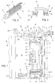
- the heating cabinet 1 ( figure 1 ) is part of a cabinet battery 1c, 1b, 1, 1a etc. identical identical arranged side by side in a row in a room which we see the floor 2 and an outer wall 3.
- Each cabinet has an access door 4 located on its front side. All doors 4 are accessible from the same side (the side seen from the front of the figure 1 ) of the row are located substantially in the same vertical plane.
- the heating cabinet comprises a set of walls defining at least one inner compartment 6 designed to receive wet or wet clothes 5. These walls comprise a rear wall 7, an upper wall 8, two side walls 9 and a bottom 11. The door 4 gives access to compartment 6.
- Means 12 are provided for blowing air into the compartment 6.
- the blowing means 12 which is better visible on the figure 3 , comprise a cylindrical turbine 13 elongated axially blowing the air through a slot 14 parallel to the axis 16 of the turbine.
- the blowing means 12 are installed so that the slot 14 and the axis 16 are parallel to the width of the cabinet.
- the turbine 13 is driven by an electric motor 17.
- the axial length of the turbine 13 and the length of the slot 14 are chosen to be little less than the width of the compartment 6.
- the blowing means 12 are installed in a lower housing 18 located under the bottom 11 of the compartment 6.
- the housing 18 is connected to the outside by a suction grille 19 mounted in an opening of the door 4, and through which passes the air sucked by the blowing means 12.
- the lower housing 18 is a shoe compartment 20.
- the blowing means 12 are supported and protected by a housing 21 which is fixed under the bottom 11 and against the rear wall 7 of the cabinet.
- the housing 21 is suitably perforated so that the blowing means can suck the air coming from the grid 19.
- the discharge slot 14 of the blowing means 12 is placed in correspondence with an elongate opening 22 formed in the bottom 11 along the rear wall 7.
- the elongated opening 22 is covered by a hood 23 provided with a ventilation grid 24 extending in an oblique plane and through which the air discharged by the blowing means 12 reaches the inside of the compartment 6.
- Heating means 26 are arranged to heat the blown air shortly before it enters the compartment 6.
- the heating means 26 comprise, in the example described, an elongated electric heating element 27 placed longitudinally in the discharge slot 14 of the heating means. 12. Thus the air passing through the slot 14 is heated in contact with the heating element 27 before entering the compartment 6.
- a mouth 28 is provided in the upper wall 8 of the cabinet 1 for the evacuation of moist air out of the compartment 6.
- the discharge mouth 28 is connected to extraction means 29 ( figure 1 ) that suck the moist air into the compartment 6 and expel this moist air outside the room where the cabinet 1 is installed.
- the extraction means 29 comprise an electric extractor 31 mounted in an opening 32 of the wall 3 delimiting the room.
- the outlet mouth 28 is connected to the extraction means 29 via a manifold 33 which can collect the moist air coming from all the heating cabinets 1c, 1b, 1, 1a of the battery ( Figure 1 ).
- the manifold For each cabinet, the manifold comprises a tubular connection T 34 whose leg 36 is connected to the mouth 28 and thus communicates with the inside of the heating cabinet and in particular with its compartment 6.
- the manifold 33 further comprises pipes 37 each having an end which can be removably connected to one of the legs 38 of the T and the other end can be connected to a branch 38 of T of a tubular connector of a similar adjacent cabinet.
- the pipes are preferably rectilinear, as shown.
- the pipes 37 and the branches 38 of the connectors 34 are preferably larger in diameter than the mouths 28 and the legs 36 of the connectors 34, as can be seen in FIG. figure 2 . More generally, by reducing the passage section for the air extracted at the cabinet outlet relative to the passage section for the exhaust air common to several cabinets, it promotes a fair distribution of suction in the various cabinets.
- the branches 38 of the T are parallel to a direction of alignment of the cabinets, or parallel to the width of the cabinets.
- the removable connection is then, even more preferably, a fitting that is removable by separating the heating cabinet and the adjacent cabinet from each other which are connected together by this pipe, as shown with respect to the pipe 37b at the figure 1 while one is in the process, for example for a maintenance operation, to move the cabinet 1c away from the cabinet 1b following the arrow 39 parallel to the width of the cabinets.
- the collector 33 is located on the top of the cabinet and is masked by a fairing 41 (see figure 3 , the fairing being omitted at the figure 1 for better visibility of the collector). It is particularly advantageous that the fairing extends obliquely rearward from its lower edge 42 near an upper edge of a front face of the cabinet. Thus arranged the fairing prevents the deposit of various items, such as empty cans or food scraps, on the top of the cupboard.
- Power supply means are provided for the blowing means 12 and the heating means 26. These supply means comprise n common conductors, namely two conductors 43, 44 in the simple example shown. One of the conductors passes through a door contact 46 and an on-off switch 47. When the door 4 is open the door contact interrupts the supply of the blowing means 12 and the heating means 26.
- the switch on-off 47 allows, at will, to operate or stop simultaneously the blowing means 12 and the heating means 26 of a cabinet independently of the others in the row.
- the n common conductors ramify to supply by a branch 48 the motor 17 of the blowing means.
- the other branch 49 supplies the heating means 26 via a thermostat 51 which is sensitive to the temperature in the compartment 6.
- the thermostat 51 opens the branch 49 and thus stops the heating means 26 when the temperature exceeds a high threshold, and puts into operation the heating means when the temperature becomes below a low threshold. Temperatures of the order of 30 ° C. in compartment 6 are suitable.
- the cabinet is designed to be connected to a power supply common to all the cabinets 1c, 1b, 1, 1a of the battery.
- the aforementioned power supply means 43, 44 are supplied by a connection to the bus line, as shown in FIG. figure 1 .
- the bus lines 52 of the adjacent cabinets are interconnected by electrical connections 54 with n conductors, which each comprise at its two ends, two connecting means 56 suitably arranged and spaced to connect one of the plugs of a heating cabinet with a plug of the adjacent cabinet.
- the connecting means 56 may comprise insulating protective caps 57 which are pushed by springs 58 in a position where for the safety of persons and the installation they prevent access to the contacts when a connection means 56 is disconnected (left side of the figure 4 ).
- the connecting means 56 When connecting a connection means 56 to a socket 53 the latter automatically pushes the cap 57 against its spring 58 (see right part of the figure 4 ).
- jumpers 54 are on the top of the cabinets and the movement for their insertion or extraction is vertical.
- the bus lines 52 are connected to a voltage source. For this, it can be provided on each cabinet or on a particular cabinet a socket 59 or a power cord (not shown), one or the other connected to the bus line of this cabinet. In use only one cabinet is connected to a power source and all other cabinets are powered by the bus lines 52 connected together by the connectors 54. It is also possible, for example, to provide a connection such as 54 special (not shown) whose conductors are further connected to a cordon terminated by a conventional plug that can be plugged into a socket wall socket of the room. Again we go through a single connection to the network power all the cabinet battery.
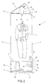
- the inner compartment 6, or compartment drying occupies only part of the width of the cabinet.
- the cabinet further contains a second compartment 66 which is separated from the drying compartment 6 by a vertical partition 71 and which occupies the rest of the width of the cabinet.
- blowing means 12 and the heating means 26, represented in a simplified manner at the Figure 7 are shorter, in the sense of the width of the cabinet, than in the example of the Figure 1 , to extend only below the drying compartment 6 and to send hot air only into it.
- the second compartment is substantially isolated from the air flow generated by the blowing means 12 by the above-mentioned partition 71, by a floor 72 which separates the second compartment 66 from the lower shoe compartment 18 here equipped with substantially horizontal support rods 73 for shoes or boots 20, and an intermediate ceiling 74 for separation with an upper housing 76 where one can, for example, store protective helmets.
- the walls 71, 72, 74 each have a respective leading edge 81, 82, 84, which together form a continuous seal with the interior face of a cabinet door, and a rear edge (not shown) which is joined with the bottom 7 of the cabinet.
- the second compartment 66 is thus isolated from the direct action of the heating means, while being moderately heated by the walls 71 and 74 exposed to the hot environment by their side adjacent to the drying compartment 6 and the upper housing 76.
- the drying compartment 6 is separated from the upper housing 76 by an extension of the intermediate ceiling 74. However, an air passage slot is provided between this extension and the door.
- the front edge 86 of the intermediate ceiling 74 is shifted rearwardly relative to the front edge 84 to allow air propelled by the blowing means 12 to pass from the compartment drying 6 in the upper housing 76 and thence in the manifold 33 ( Figure 1 ).
- the cabinet preferably comprises two doors 87 opening preferably "French", that is to say being articulated each around its vertical edge opposite the other door.
- One of the doors gives access to the drying compartment 6, the other to the second compartment 66.
- the cabinet has underbody a trunk 88 which protrudes forward relative to the front of the rest of the cabinet.
- the trunk 88 thus comprises in the front part an upper wall 89 which can serve as a seat for the user.
- this upper wall is retractable under the main body of the cabinet to provide access to the interior volume of the trunk can be used for storing various objects (tools, sports accessories, etc.).
- the upper wall 89 consists of 3 flaps which slide telescopically.
- the interior volume of the trunk 88 is ventilated by a grid 91.
- the interior volume of the trunk is isolated by a fixed wall of the interior volume of the main body of the cabinet, in particular, in the example, the lower housing 18.
- the cabinet may be an individual cabinet and not a modular battery cabinet.
- the blowing means a suction duct that comes directly from outside the cabinet, without the air passes through a housing such as the shoe compartment of the example described, the presence of which is not mandatory.
- At least one infrared heating panel may be provided in the compartment 6, placed for example against the rear vertical face of the drying compartment 6.
- the connector 54 may be a rigid U-shaped jumper for extracting the two connection means 56 by one and the same extraction movement both of one of the jacks 53 of the heating cabinet and a socket 53 of the adjacent cabinet.
- one of the hoses 37 may be a special hose comprising a lateral tapping which connects to the extraction means by a sheath (not shown).
Landscapes
- Engineering & Computer Science (AREA)
- Textile Engineering (AREA)
- Drying Of Solid Materials (AREA)
- Central Heating Systems (AREA)
Claims (18)
- Wärmeschrank, umfassend:- Wände (7, 8, 9, 11), die mindestens eine Innenkammer (6) zur Aufnahme feuchter oder nasser Kleidungsstücke (5) eingrenzen,- Einrichtungen (12), um Luft in die Kammer hineinzublasen,- Heizeinrichtungen (26), um die in die Kammer (6) hineingeblasene Luft zu heizen,- eine Abzugsmündung (28) zum Abzug der feuchten Luft ausserhalb der Innenkammer (6) hinweg,dadurch gekennzeichnet, dass die Abzugsmündung (28) an Abzugseinrichtungen (29) angeschlossen sein kann, welche die feuchte Luft aus einem Raum heraus fördern, in dem der Schrank aufgebaut ist,
und dadurch, dass die Abzugsmündung (28) an den Abzugseinrichtungen (29) durch einen Abscheider (33) angeschlossen sein kann, welcher die feuchte Luft aus mehreren, in Batterie aufgestellten Wärmeschränken (1, 1a, 1b, 1c) sammeln kann. - Wärmeschrank nach Anspruch 1, dadurch gekennzeichnet, dass der Abscheider eine T-Rohrverbindung (34), deren Schenkel (36) mit der Innenseite des Wärmeschranks (1) verbunden ist, und wenigstens ein Rohr (37) umfasst, dessen ein Ende an einem der Arme (38) des T abnehmbar angeschlossen werden kann und das andere Ende an einem T-Arm einer Rohrverbindung eines ähnlichen Nachbarschranks angeschlossen werden kann.
- Wärmeschrank nach Anspruch 2, dadurch gekennzeichnet, dass:- die Arme (38) des T parallel zu einer Fluchtlinienrichtung der Schränke verlaufen,- es sich bei dem abnehmbaren Anschluss um eine Steckverbindung handelt, die dadurch aufgetrennt werden kann, dass der Wärmeschrank (1c) und der Nachbarschrank (1b) auseinander gezogen werden.
- Wärmeschrank nach Anspruch 1, dadurch gekennzeichnet, dass der auf der Oberseite des Schranks gelagerte Abscheider (33) durch eine schräge Verkleidung (41) abgedeckt ist, deren Unterkante (42) nah an einer Oberkante einer Vorderseite des Schranks angeordnet ist, wobei die Verkleidung das Ablegen verschiedener Gegenstände auf der Oberseite des Schranks verhindert.
- Wärmeschrank nach einem der Ansprüche 1-4, dadurch gekennzeichnet, dass die Gebläseeinrichtungen (12) eine axial langgestreckte, zylindrische Turbine (13) umfasst, welche die Luft durch einen Schlitz (14) parallel zur Achse (16) der Turbine bläst, wobei die Achse parallel zu einer Breite des Schranks verläuft.
- Wärmeschrank nach einem der Ansprüche 1-5, dadurch gekennzeichnet, dass die Gebläseeinrichtungen (12) in einer unteren Aufnahme (18) aufgenommen sind, welche unter der Kammer (6) gelagert und über ein Ansauggitter (19) nach außen hin angeschlossen ist.
- Wärmeschrank nach einem der Ansprüche 1-6, dadurch gekennzeichnet, dass die Gebläseeinrichtungen (12) in einer unteren Aufnahme (18) aufgenommen sind, welche unter der Kammer (6) gelagert und als Schuhfach (20) verwendbar ist.
- Wärmeschrank nach einem der Ansprüche 1-7, dadurch gekennzeichnet, dass die geblasene und aufgewärmte Luft in die Kammer (6) über eine Gebläsemündung (24) hinein geblasen wird, welche durch eine vertikale oder geneigte Wand hindurch vorgesehen und nahe vom Boden und von der Rückwand der Kammer (6) gelagert ist.
- Wärmeschrank nach einem der Ansprüche 1-8, dadurch gekennzeichnet, dass die Heizeinrichtungen (26) durch einen nach der Temperatur in der Kammer (6) reagierenden Thermostat (51) geregelt werden.
- Wärmeschrank nach einem der Ansprüche 1-9, dadurch gekennzeichnet, dass er mindestens eine Tür (4) zur Kammer (6) umfasst, welche mit einem Kontakt (46) ausgestattet ist, der ein Abschalten der Heizeinrichtungen (26) und der Gebläseeinrichtungen (12) bei geöffneter Tür (4) steuert.
- Wärmeschrank nach einem der Ansprüche 1-10, dadurch gekennzeichnet, dass er dafür geeignet ist, an einer mit mindestens einem weiteren ähnlichen Schrank zusammen geteilten Stromversorgung angeschlossen zu sein, und dass er einen individuellen Ein/Aus-Schalter (47) umfasst, welcher das beliebige Ausschalten des Wärmeschranks unabhängig von dem mindestens einen ähnlichen Schrank ermöglicht.
- Wärmeschrank nach einem der Ansprüche 1-11, dadurch gekennzeichnet, dass er eine Busleitung (52) zur Versorgung der Gebläse- (12) und Heizeinrichtungen (26) umfasst, und dass die Busleitung (52) sich zwischen zwei Steckern (53) erstreckt, die jeweils ermöglichen, dass die Busleitung mit einer ähnlichen Busleitung eines mit einer jeweiligen Seitenwand des Wärmeschranks benachbart stehenden Schranks verbunden wird.
- Wärmeschrank nach Anspruch 12, dadurch gekennzeichnet, dass er mindestens einen elektrischen Mehrleiter-Anschluss (54) für den Anschluss mit dem mindestens einen ähnlichen Schrank umfasst, wobei der Anschluss an seinen beiden Enden zwei Verbindungs-einrichtungen (56) umfasst, welche angemessen angeordnet und beabstandet sind, um einen der Stecker (53) des Wärmeschranks mit einem Stecker des Nachbarschranks zu verbinden.
- Wärmeschrank nach einem der Ansprüche 1-13, dadurch gekennzeichnet, dass er außerdem neben der Innen-Trockenkammer (6) zur Aufnahme feuchter Kleidungsstücke eine zweite Kammer (66) umfasst, die wenigstens annähernd vor dem in der Innenkammer (6) erzeugten Luftstrom und/oder vor der direkten Einwirkung der Heizeinrichtungen (26) geschützt ist.
- Wärmeschrank nach Anspruch 14, dadurch gekennzeichnet, dass die zweite Kammer (66) durch mindestens eine Trennwand (71) begrenzt ist, welche eine Vorderkante (81) aufweist, die mit einer Tür (87) des Schranks bei geschlossener Tür im Wesentlichen zusammenstoßend angeordnet ist.
- Wärmeschrank nach Anspruch 14, dadurch gekennzeichnet, dass der Schrank eine Tür (87) zur Innen-Trockenkammer (6) und eine Tür (87) zur zweiten Kammer (66) umfasst.
- Wärmeschrank nach einem der Ansprüche 1-16, dadurch gekennzeichnet, dass sie im unteren Bereich eine Lade (88) umfasst, welche nach vorne herausragt und mit ihrer oberen Wand (89) einen Sitz für den Benutzer bildet.
- Wärmeschrank nach einem der Ansprüche 1-17, dadurch gekennzeichnet, dass er insbesondere zur Ausstattung eines als Umkleide fungierenden Raums für außen ausgeübte Aktivitäten wie Baustellen, sportliche Außenaktivitäten, usw. bestimmt ist.
Applications Claiming Priority (1)
| Application Number | Priority Date | Filing Date | Title |
|---|---|---|---|
| FR1252468A FR2988408B1 (fr) | 2012-03-20 | 2012-03-20 | Armoire chauffante |
Publications (2)
| Publication Number | Publication Date |
|---|---|
| EP2642016A1 EP2642016A1 (de) | 2013-09-25 |
| EP2642016B1 true EP2642016B1 (de) | 2016-05-11 |
Family
ID=47884207
Family Applications (1)
| Application Number | Title | Priority Date | Filing Date |
|---|---|---|---|
| EP13160204.7A Active EP2642016B1 (de) | 2012-03-20 | 2013-03-20 | Heizschrank |
Country Status (2)
| Country | Link |
|---|---|
| EP (1) | EP2642016B1 (de) |
| FR (1) | FR2988408B1 (de) |
Families Citing this family (1)
| Publication number | Priority date | Publication date | Assignee | Title |
|---|---|---|---|---|
| FR3018084B1 (fr) * | 2014-03-03 | 2017-03-24 | Gilles Soreau | Ensemble mobilier pour le stockage et le sechage d'articles vestimentaires et chaussures |
Family Cites Families (4)
| Publication number | Priority date | Publication date | Assignee | Title |
|---|---|---|---|---|
| FR1472827A (fr) * | 1966-03-29 | 1967-03-10 | Armoire de séchage accéléré | |
| JPH04187195A (ja) * | 1990-11-21 | 1992-07-03 | Ngk Insulators Ltd | 衣類乾燥機 |
| FR2909105B1 (fr) | 2006-11-27 | 2009-01-09 | Algeco Sa | Armoire de sechage. |
| TWM354618U (en) * | 2008-10-15 | 2009-04-11 | Feng-Yin Yang | Cool air dryer |
-
2012
- 2012-03-20 FR FR1252468A patent/FR2988408B1/fr active Active
-
2013
- 2013-03-20 EP EP13160204.7A patent/EP2642016B1/de active Active
Non-Patent Citations (1)
| Title |
|---|
| None * |
Also Published As
| Publication number | Publication date |
|---|---|
| FR2988408A1 (fr) | 2013-09-27 |
| FR2988408B1 (fr) | 2014-11-28 |
| EP2642016A1 (de) | 2013-09-25 |
Similar Documents
| Publication | Publication Date | Title |
|---|---|---|
| FR2921079A1 (fr) | Machine a laver du type a tambour. | |
| WO2007149996A2 (en) | Ventilated toilet apparatus and dual function toilet seat | |
| FR2638627A1 (de) | ||
| EP2915914B1 (de) | Möbeleinheit zum Lagern und Trocknen von Bekleidungsartikeln und Schuhen | |
| EP2642016B1 (de) | Heizschrank | |
| FR2580467A1 (fr) | Niche de sechage | |
| EP0251898B1 (de) | Dusch- und Wäschetrockenvorrichtung | |
| FR2761620A1 (fr) | Hotte aspirante de table | |
| EP1925711B1 (de) | Trocknungsschrank | |
| FR3053210A1 (fr) | Dispositif d’irrigation d’un systeme de vegetalisation | |
| EP1582129B1 (de) | Einrichtung zur Wäschetrocknung und Raumbeheizung mit Warmluftausgang im Sammelrohr | |
| WO2009068773A2 (fr) | Systeme de sechage corporel a air chaud. | |
| FR3007618A1 (fr) | Armoire d'exterieur a rafraichissement aeraulique | |
| KR100637881B1 (ko) | 신발 건조장치 | |
| EP1180648A1 (de) | Motorisierte Abzugshaube für Küchen | |
| KR200357289Y1 (ko) | 신발 건조장치 | |
| WO2009044047A2 (fr) | Procede et dispositif pour extraire un gaz d'une structure maconnee | |
| EP1038739A1 (de) | Verfahren zum Reinigen und Trocknungsvorrichtung für das Kraftfahrzeuginnere | |
| FR2670367A1 (fr) | Installation de sechage de plantes. | |
| FR3066254A1 (fr) | Convecteur electrique reproduisant l'effet cheminee, maitrisant la chaleur, retardant les deperditions, assurant rapidement 20 a 22° celsius | |
| FR3099693A1 (fr) | Appareil de séchage | |
| FR2577306A1 (fr) | Appareil de chauffage fonctionnant avec les combustibles gazeux, destine a etre raccorde a un conduit de fumee. | |
| CN115736783A (zh) | 一种基于智能家居的多功能鞋柜 | |
| FR2949843A1 (fr) | Corps de chauffe a plusieurs entrees d'air de combustion et a organe de commande unique | |
| FR2581169A1 (fr) | Systeme de deshumidification pour chambre de conservation et de fermentation des pates a pain |
Legal Events
| Date | Code | Title | Description |
|---|---|---|---|
| PUAI | Public reference made under article 153(3) epc to a published international application that has entered the european phase |
Free format text: ORIGINAL CODE: 0009012 |
|
| AK | Designated contracting states |
Kind code of ref document: A1 Designated state(s): AL AT BE BG CH CY CZ DE DK EE ES FI FR GB GR HR HU IE IS IT LI LT LU LV MC MK MT NL NO PL PT RO RS SE SI SK SM TR |
|
| AX | Request for extension of the european patent |
Extension state: BA ME |
|
| 17P | Request for examination filed |
Effective date: 20140307 |
|
| RAX | Requested extension states of the european patent have changed |
Extension state: BA Payment date: 20140307 Extension state: ME Payment date: 20140307 |
|
| RBV | Designated contracting states (corrected) |
Designated state(s): AL AT BE BG CH CY CZ DE DK EE ES FI FR GB GR HR HU IE IS IT LI LT LU LV MC MK MT NL NO PL PT RO RS SE SI SK SM TR |
|
| GRAP | Despatch of communication of intention to grant a patent |
Free format text: ORIGINAL CODE: EPIDOSNIGR1 |
|
| INTG | Intention to grant announced |
Effective date: 20151028 |
|
| GRAS | Grant fee paid |
Free format text: ORIGINAL CODE: EPIDOSNIGR3 |
|
| GRAP | Despatch of communication of intention to grant a patent |
Free format text: ORIGINAL CODE: EPIDOSNIGR1 |
|
| INTG | Intention to grant announced |
Effective date: 20160310 |
|
| GRAA | (expected) grant |
Free format text: ORIGINAL CODE: 0009210 |
|
| AK | Designated contracting states |
Kind code of ref document: B1 Designated state(s): AL AT BE BG CH CY CZ DE DK EE ES FI FR GB GR HR HU IE IS IT LI LT LU LV MC MK MT NL NO PL PT RO RS SE SI SK SM TR |
|
| AX | Request for extension of the european patent |
Extension state: BA ME |
|
| REG | Reference to a national code |
Ref country code: GB Ref legal event code: FG4D Free format text: NOT ENGLISH |
|
| REG | Reference to a national code |
Ref country code: CH Ref legal event code: EP |
|
| REG | Reference to a national code |
Ref country code: AT Ref legal event code: REF Ref document number: 798770 Country of ref document: AT Kind code of ref document: T Effective date: 20160515 |
|
| REG | Reference to a national code |
Ref country code: IE Ref legal event code: FG4D Free format text: LANGUAGE OF EP DOCUMENT: FRENCH |
|
| REG | Reference to a national code |
Ref country code: DE Ref legal event code: R096 Ref document number: 602013007374 Country of ref document: DE |
|
| REG | Reference to a national code |
Ref country code: NL Ref legal event code: FP |
|
| REG | Reference to a national code |
Ref country code: LT Ref legal event code: MG4D |
|
| PG25 | Lapsed in a contracting state [announced via postgrant information from national office to epo] |
Ref country code: LT Free format text: LAPSE BECAUSE OF FAILURE TO SUBMIT A TRANSLATION OF THE DESCRIPTION OR TO PAY THE FEE WITHIN THE PRESCRIBED TIME-LIMIT Effective date: 20160511 Ref country code: FI Free format text: LAPSE BECAUSE OF FAILURE TO SUBMIT A TRANSLATION OF THE DESCRIPTION OR TO PAY THE FEE WITHIN THE PRESCRIBED TIME-LIMIT Effective date: 20160511 Ref country code: NO Free format text: LAPSE BECAUSE OF FAILURE TO SUBMIT A TRANSLATION OF THE DESCRIPTION OR TO PAY THE FEE WITHIN THE PRESCRIBED TIME-LIMIT Effective date: 20160811 |
|
| REG | Reference to a national code |
Ref country code: AT Ref legal event code: MK05 Ref document number: 798770 Country of ref document: AT Kind code of ref document: T Effective date: 20160511 |
|
| PG25 | Lapsed in a contracting state [announced via postgrant information from national office to epo] |
Ref country code: RS Free format text: LAPSE BECAUSE OF FAILURE TO SUBMIT A TRANSLATION OF THE DESCRIPTION OR TO PAY THE FEE WITHIN THE PRESCRIBED TIME-LIMIT Effective date: 20160511 Ref country code: SE Free format text: LAPSE BECAUSE OF FAILURE TO SUBMIT A TRANSLATION OF THE DESCRIPTION OR TO PAY THE FEE WITHIN THE PRESCRIBED TIME-LIMIT Effective date: 20160511 Ref country code: GR Free format text: LAPSE BECAUSE OF FAILURE TO SUBMIT A TRANSLATION OF THE DESCRIPTION OR TO PAY THE FEE WITHIN THE PRESCRIBED TIME-LIMIT Effective date: 20160812 Ref country code: LV Free format text: LAPSE BECAUSE OF FAILURE TO SUBMIT A TRANSLATION OF THE DESCRIPTION OR TO PAY THE FEE WITHIN THE PRESCRIBED TIME-LIMIT Effective date: 20160511 Ref country code: ES Free format text: LAPSE BECAUSE OF FAILURE TO SUBMIT A TRANSLATION OF THE DESCRIPTION OR TO PAY THE FEE WITHIN THE PRESCRIBED TIME-LIMIT Effective date: 20160511 Ref country code: PT Free format text: LAPSE BECAUSE OF FAILURE TO SUBMIT A TRANSLATION OF THE DESCRIPTION OR TO PAY THE FEE WITHIN THE PRESCRIBED TIME-LIMIT Effective date: 20160912 Ref country code: HR Free format text: LAPSE BECAUSE OF FAILURE TO SUBMIT A TRANSLATION OF THE DESCRIPTION OR TO PAY THE FEE WITHIN THE PRESCRIBED TIME-LIMIT Effective date: 20160511 |
|
| PG25 | Lapsed in a contracting state [announced via postgrant information from national office to epo] |
Ref country code: IT Free format text: LAPSE BECAUSE OF FAILURE TO SUBMIT A TRANSLATION OF THE DESCRIPTION OR TO PAY THE FEE WITHIN THE PRESCRIBED TIME-LIMIT Effective date: 20160511 |
|
| PG25 | Lapsed in a contracting state [announced via postgrant information from national office to epo] |
Ref country code: EE Free format text: LAPSE BECAUSE OF FAILURE TO SUBMIT A TRANSLATION OF THE DESCRIPTION OR TO PAY THE FEE WITHIN THE PRESCRIBED TIME-LIMIT Effective date: 20160511 Ref country code: DK Free format text: LAPSE BECAUSE OF FAILURE TO SUBMIT A TRANSLATION OF THE DESCRIPTION OR TO PAY THE FEE WITHIN THE PRESCRIBED TIME-LIMIT Effective date: 20160511 Ref country code: RO Free format text: LAPSE BECAUSE OF FAILURE TO SUBMIT A TRANSLATION OF THE DESCRIPTION OR TO PAY THE FEE WITHIN THE PRESCRIBED TIME-LIMIT Effective date: 20160511 Ref country code: SK Free format text: LAPSE BECAUSE OF FAILURE TO SUBMIT A TRANSLATION OF THE DESCRIPTION OR TO PAY THE FEE WITHIN THE PRESCRIBED TIME-LIMIT Effective date: 20160511 Ref country code: CZ Free format text: LAPSE BECAUSE OF FAILURE TO SUBMIT A TRANSLATION OF THE DESCRIPTION OR TO PAY THE FEE WITHIN THE PRESCRIBED TIME-LIMIT Effective date: 20160511 |
|
| REG | Reference to a national code |
Ref country code: DE Ref legal event code: R097 Ref document number: 602013007374 Country of ref document: DE |
|
| PG25 | Lapsed in a contracting state [announced via postgrant information from national office to epo] |
Ref country code: AT Free format text: LAPSE BECAUSE OF FAILURE TO SUBMIT A TRANSLATION OF THE DESCRIPTION OR TO PAY THE FEE WITHIN THE PRESCRIBED TIME-LIMIT Effective date: 20160511 Ref country code: SM Free format text: LAPSE BECAUSE OF FAILURE TO SUBMIT A TRANSLATION OF THE DESCRIPTION OR TO PAY THE FEE WITHIN THE PRESCRIBED TIME-LIMIT Effective date: 20160511 Ref country code: PL Free format text: LAPSE BECAUSE OF FAILURE TO SUBMIT A TRANSLATION OF THE DESCRIPTION OR TO PAY THE FEE WITHIN THE PRESCRIBED TIME-LIMIT Effective date: 20160511 |
|
| PLBE | No opposition filed within time limit |
Free format text: ORIGINAL CODE: 0009261 |
|
| STAA | Information on the status of an ep patent application or granted ep patent |
Free format text: STATUS: NO OPPOSITION FILED WITHIN TIME LIMIT |
|
| REG | Reference to a national code |
Ref country code: FR Ref legal event code: PLFP Year of fee payment: 5 |
|
| 26N | No opposition filed |
Effective date: 20170214 |
|
| PG25 | Lapsed in a contracting state [announced via postgrant information from national office to epo] |
Ref country code: SI Free format text: LAPSE BECAUSE OF FAILURE TO SUBMIT A TRANSLATION OF THE DESCRIPTION OR TO PAY THE FEE WITHIN THE PRESCRIBED TIME-LIMIT Effective date: 20160511 |
|
| PG25 | Lapsed in a contracting state [announced via postgrant information from national office to epo] |
Ref country code: MC Free format text: LAPSE BECAUSE OF FAILURE TO SUBMIT A TRANSLATION OF THE DESCRIPTION OR TO PAY THE FEE WITHIN THE PRESCRIBED TIME-LIMIT Effective date: 20160511 |
|
| REG | Reference to a national code |
Ref country code: IE Ref legal event code: MM4A |
|
| PG25 | Lapsed in a contracting state [announced via postgrant information from national office to epo] |
Ref country code: LU Free format text: LAPSE BECAUSE OF NON-PAYMENT OF DUE FEES Effective date: 20170320 |
|
| PG25 | Lapsed in a contracting state [announced via postgrant information from national office to epo] |
Ref country code: IE Free format text: LAPSE BECAUSE OF NON-PAYMENT OF DUE FEES Effective date: 20170320 |
|
| REG | Reference to a national code |
Ref country code: FR Ref legal event code: PLFP Year of fee payment: 6 |
|
| PG25 | Lapsed in a contracting state [announced via postgrant information from national office to epo] |
Ref country code: MT Free format text: LAPSE BECAUSE OF FAILURE TO SUBMIT A TRANSLATION OF THE DESCRIPTION OR TO PAY THE FEE WITHIN THE PRESCRIBED TIME-LIMIT Effective date: 20160511 |
|
| PG25 | Lapsed in a contracting state [announced via postgrant information from national office to epo] |
Ref country code: AL Free format text: LAPSE BECAUSE OF FAILURE TO SUBMIT A TRANSLATION OF THE DESCRIPTION OR TO PAY THE FEE WITHIN THE PRESCRIBED TIME-LIMIT Effective date: 20160511 |
|
| PG25 | Lapsed in a contracting state [announced via postgrant information from national office to epo] |
Ref country code: HU Free format text: LAPSE BECAUSE OF FAILURE TO SUBMIT A TRANSLATION OF THE DESCRIPTION OR TO PAY THE FEE WITHIN THE PRESCRIBED TIME-LIMIT; INVALID AB INITIO Effective date: 20130320 |
|
| PG25 | Lapsed in a contracting state [announced via postgrant information from national office to epo] |
Ref country code: BG Free format text: LAPSE BECAUSE OF FAILURE TO SUBMIT A TRANSLATION OF THE DESCRIPTION OR TO PAY THE FEE WITHIN THE PRESCRIBED TIME-LIMIT Effective date: 20160511 |
|
| PG25 | Lapsed in a contracting state [announced via postgrant information from national office to epo] |
Ref country code: CY Free format text: LAPSE BECAUSE OF NON-PAYMENT OF DUE FEES Effective date: 20160511 |
|
| PG25 | Lapsed in a contracting state [announced via postgrant information from national office to epo] |
Ref country code: MK Free format text: LAPSE BECAUSE OF FAILURE TO SUBMIT A TRANSLATION OF THE DESCRIPTION OR TO PAY THE FEE WITHIN THE PRESCRIBED TIME-LIMIT Effective date: 20160511 |
|
| PG25 | Lapsed in a contracting state [announced via postgrant information from national office to epo] |
Ref country code: TR Free format text: LAPSE BECAUSE OF FAILURE TO SUBMIT A TRANSLATION OF THE DESCRIPTION OR TO PAY THE FEE WITHIN THE PRESCRIBED TIME-LIMIT Effective date: 20160511 |
|
| PG25 | Lapsed in a contracting state [announced via postgrant information from national office to epo] |
Ref country code: IS Free format text: LAPSE BECAUSE OF FAILURE TO SUBMIT A TRANSLATION OF THE DESCRIPTION OR TO PAY THE FEE WITHIN THE PRESCRIBED TIME-LIMIT Effective date: 20160911 |
|
| PGFP | Annual fee paid to national office [announced via postgrant information from national office to epo] |
Ref country code: GB Payment date: 20230330 Year of fee payment: 11 Ref country code: DE Payment date: 20230330 Year of fee payment: 11 Ref country code: BE Payment date: 20230330 Year of fee payment: 11 |
|
| PGFP | Annual fee paid to national office [announced via postgrant information from national office to epo] |
Ref country code: NL Payment date: 20230330 Year of fee payment: 11 |
|
| PGFP | Annual fee paid to national office [announced via postgrant information from national office to epo] |
Ref country code: CH Payment date: 20230404 Year of fee payment: 11 |
|
| REG | Reference to a national code |
Ref country code: DE Ref legal event code: R119 Ref document number: 602013007374 Country of ref document: DE |
|
| REG | Reference to a national code |
Ref country code: CH Ref legal event code: PL |
|
| REG | Reference to a national code |
Ref country code: NL Ref legal event code: MM Effective date: 20240401 |
|
| GBPC | Gb: european patent ceased through non-payment of renewal fee |
Effective date: 20240320 |
|
| PG25 | Lapsed in a contracting state [announced via postgrant information from national office to epo] |
Ref country code: NL Free format text: LAPSE BECAUSE OF NON-PAYMENT OF DUE FEES Effective date: 20240401 |
|
| REG | Reference to a national code |
Ref country code: BE Ref legal event code: MM Effective date: 20240331 |
|
| PG25 | Lapsed in a contracting state [announced via postgrant information from national office to epo] |
Ref country code: NL Free format text: LAPSE BECAUSE OF NON-PAYMENT OF DUE FEES Effective date: 20240401 |
|
| PG25 | Lapsed in a contracting state [announced via postgrant information from national office to epo] |
Ref country code: DE Free format text: LAPSE BECAUSE OF NON-PAYMENT OF DUE FEES Effective date: 20241001 |
|
| PG25 | Lapsed in a contracting state [announced via postgrant information from national office to epo] |
Ref country code: BE Free format text: LAPSE BECAUSE OF NON-PAYMENT OF DUE FEES Effective date: 20240331 |
|
| PG25 | Lapsed in a contracting state [announced via postgrant information from national office to epo] |
Ref country code: GB Free format text: LAPSE BECAUSE OF NON-PAYMENT OF DUE FEES Effective date: 20240320 |
|
| PG25 | Lapsed in a contracting state [announced via postgrant information from national office to epo] |
Ref country code: GB Free format text: LAPSE BECAUSE OF NON-PAYMENT OF DUE FEES Effective date: 20240320 Ref country code: DE Free format text: LAPSE BECAUSE OF NON-PAYMENT OF DUE FEES Effective date: 20241001 Ref country code: BE Free format text: LAPSE BECAUSE OF NON-PAYMENT OF DUE FEES Effective date: 20240331 Ref country code: CH Free format text: LAPSE BECAUSE OF NON-PAYMENT OF DUE FEES Effective date: 20240331 |
|
| PGFP | Annual fee paid to national office [announced via postgrant information from national office to epo] |
Ref country code: FR Payment date: 20260327 Year of fee payment: 14 |