EP2641817B1 - Loading floor and profiled element for a loading floor - Google Patents
Loading floor and profiled element for a loading floor Download PDFInfo
- Publication number
- EP2641817B1 EP2641817B1 EP13158084.7A EP13158084A EP2641817B1 EP 2641817 B1 EP2641817 B1 EP 2641817B1 EP 13158084 A EP13158084 A EP 13158084A EP 2641817 B1 EP2641817 B1 EP 2641817B1
- Authority
- EP
- European Patent Office
- Prior art keywords
- loading floor
- longitudinal direction
- continuous
- vehicle
- air conditioning
- Prior art date
- Legal status (The legal status is an assumption and is not a legal conclusion. Google has not performed a legal analysis and makes no representation as to the accuracy of the status listed.)
- Active
Links
- 238000004378 air conditioning Methods 0.000 claims description 50
- 239000011796 hollow space material Substances 0.000 claims description 11
- 238000005192 partition Methods 0.000 claims 1
- 230000001143 conditioned effect Effects 0.000 description 4
- 238000009827 uniform distribution Methods 0.000 description 3
- 238000010276 construction Methods 0.000 description 2
- 238000011109 contamination Methods 0.000 description 2
- 238000005553 drilling Methods 0.000 description 2
- 238000004519 manufacturing process Methods 0.000 description 2
- XAGFODPZIPBFFR-UHFFFAOYSA-N aluminium Chemical compound [Al] XAGFODPZIPBFFR-UHFFFAOYSA-N 0.000 description 1
- 229910052782 aluminium Inorganic materials 0.000 description 1
- 238000004873 anchoring Methods 0.000 description 1
- 230000003750 conditioning effect Effects 0.000 description 1
- 238000001125 extrusion Methods 0.000 description 1
- 238000009408 flooring Methods 0.000 description 1
- 238000010438 heat treatment Methods 0.000 description 1
- 230000037431 insertion Effects 0.000 description 1
- 238000003780 insertion Methods 0.000 description 1
- 238000009434 installation Methods 0.000 description 1
- 239000000463 material Substances 0.000 description 1
- 238000009423 ventilation Methods 0.000 description 1
Images

Classifications
-
- B—PERFORMING OPERATIONS; TRANSPORTING
- B62—LAND VEHICLES FOR TRAVELLING OTHERWISE THAN ON RAILS
- B62D—MOTOR VEHICLES; TRAILERS
- B62D21/00—Understructures, i.e. chassis frame on which a vehicle body may be mounted
- B62D21/17—Understructures, i.e. chassis frame on which a vehicle body may be mounted forming fluid or electrical conduit means or having other means to accommodate the transmission of a force or signal
-
- B—PERFORMING OPERATIONS; TRANSPORTING
- B60—VEHICLES IN GENERAL
- B60H—ARRANGEMENTS OF HEATING, COOLING, VENTILATING OR OTHER AIR-TREATING DEVICES SPECIALLY ADAPTED FOR PASSENGER OR GOODS SPACES OF VEHICLES
- B60H1/00—Heating, cooling or ventilating [HVAC] devices
- B60H1/24—Devices purely for ventilating or where the heating or cooling is irrelevant
- B60H1/241—Devices purely for ventilating or where the heating or cooling is irrelevant characterised by the location of ventilation devices in the vehicle
- B60H1/246—Devices purely for ventilating or where the heating or cooling is irrelevant characterised by the location of ventilation devices in the vehicle located in the interior of the vehicle or in or below the floor
-
- B—PERFORMING OPERATIONS; TRANSPORTING
- B60—VEHICLES IN GENERAL
- B60H—ARRANGEMENTS OF HEATING, COOLING, VENTILATING OR OTHER AIR-TREATING DEVICES SPECIALLY ADAPTED FOR PASSENGER OR GOODS SPACES OF VEHICLES
- B60H1/00—Heating, cooling or ventilating [HVAC] devices
- B60H1/00271—HVAC devices specially adapted for particular vehicle parts or components and being connected to the vehicle HVAC unit
- B60H1/00295—HVAC devices specially adapted for particular vehicle parts or components and being connected to the vehicle HVAC unit for trim components, e.g. panels, dashboards, liners
-
- B—PERFORMING OPERATIONS; TRANSPORTING
- B60—VEHICLES IN GENERAL
- B60N—SEATS SPECIALLY ADAPTED FOR VEHICLES; VEHICLE PASSENGER ACCOMMODATION NOT OTHERWISE PROVIDED FOR
- B60N2/00—Seats specially adapted for vehicles; Arrangement or mounting of seats in vehicles
- B60N2/005—Arrangement or mounting of seats in vehicles, e.g. dismountable auxiliary seats
- B60N2/015—Attaching seats directly to vehicle chassis
- B60N2/01508—Attaching seats directly to vehicle chassis using quick release attachments
- B60N2/01516—Attaching seats directly to vehicle chassis using quick release attachments with locking mechanisms
- B60N2/01558—Attaching seats directly to vehicle chassis using quick release attachments with locking mechanisms with key and slot
- B60N2/01575—Attaching seats directly to vehicle chassis using quick release attachments with locking mechanisms with key and slot key sliding inside the vehicle floor or rail
-
- B—PERFORMING OPERATIONS; TRANSPORTING
- B62—LAND VEHICLES FOR TRAVELLING OTHERWISE THAN ON RAILS
- B62D—MOTOR VEHICLES; TRAILERS
- B62D25/00—Superstructure or monocoque structure sub-units; Parts or details thereof not otherwise provided for
- B62D25/20—Floors or bottom sub-units
-
- B—PERFORMING OPERATIONS; TRANSPORTING
- B62—LAND VEHICLES FOR TRAVELLING OTHERWISE THAN ON RAILS
- B62D—MOTOR VEHICLES; TRAILERS
- B62D25/00—Superstructure or monocoque structure sub-units; Parts or details thereof not otherwise provided for
- B62D25/20—Floors or bottom sub-units
- B62D25/2054—Load carrying floors for commercial vehicles
-
- B—PERFORMING OPERATIONS; TRANSPORTING
- B62—LAND VEHICLES FOR TRAVELLING OTHERWISE THAN ON RAILS
- B62D—MOTOR VEHICLES; TRAILERS
- B62D33/00—Superstructures for load-carrying vehicles
- B62D33/04—Enclosed load compartments ; Frameworks for movable panels, tarpaulins or side curtains
- B62D33/044—Enclosed load compartments ; Frameworks for movable panels, tarpaulins or side curtains built up with profiles of constant elongated shape, e.g. extruded, mechanically interconnected by coupling members, e.g. by clamping, riveting or bolting
-
- B—PERFORMING OPERATIONS; TRANSPORTING
- B60—VEHICLES IN GENERAL
- B60H—ARRANGEMENTS OF HEATING, COOLING, VENTILATING OR OTHER AIR-TREATING DEVICES SPECIALLY ADAPTED FOR PASSENGER OR GOODS SPACES OF VEHICLES
- B60H1/00—Heating, cooling or ventilating [HVAC] devices
- B60H1/00271—HVAC devices specially adapted for particular vehicle parts or components and being connected to the vehicle HVAC unit
- B60H2001/003—Component temperature regulation using an air flow
Definitions
- the invention relates to a loading floor for a vehicle and a profile element for such a loading floor.
- the loading space of vehicles is usually provided with a loading floor fixed to a floor panel or supporting structure of the vehicle, which is designed to simplify the loading as a substantially flat surface and receives the load of the load. Furthermore, in the loading of vehicles is often the task of securely attaching objects so that they are fixed while driving on the vehicle.
- known loading floors for example, fixed eyelets for receiving lashing or on loading rails sliding fasteners that can be placed in a variety of positions and where, for example, eyelets for lashing straps are arranged.
- the loading floor may be composed of a plurality of profile elements having such loading rails.
- an optional use as a cargo space or as a passenger compartment is possible. It is possible to fix seats on the loading floor.
- a loading floor with integrated charging rails which consists of individual extruded elements which are glued together.
- a floor panel is disclosed which consists of a plurality of parallel elements each secured to a floor of a vehicle.
- the EP 1 701 860 B1 discloses a bottom plate consisting of rail profile and floor profile parts and is fixed to the floor panel of transport vehicles, the rail and floor profile parts can be mechanically locked together.
- a vehicle floor is known, which is composed of a plurality of interengaging elongate profile components, wherein some of the profile components in the longitudinal direction extending grooves for receiving anchoring elements for Attach a seat or a wheelchair holder.
- a loading floor which consists of a plurality of profile elements which are interconnected, wherein at least some profile elements comprise at least one charging rail and at least one connecting portion for connection to another profile element, wherein the loading rail has a longitudinal groove for longitudinally displaceable receiving sliding blocks and the Charging rail integrated into the respective profile element and is formed separately from the at least one connection region.
- a vehicle floor consists of a plurality of preformed interlocking flooring components having inner longitudinally extending cavities which may be used to guide cables or ventilation or also for heating purposes. As a result, however, only a temperature of the vehicle floor itself is possible.
- a chassis and / or support structure of a motor vehicle which is formed wholly or partly as a hollow chamber plate structure, wherein the hollow chamber plates may be formed as extruded profiles.
- flow channels are formed within the chassis and / or the support structure, wherein a passenger compartment is vented through the or part of the flow channels.
- a temperature controlled container wherein the bottom of the container comprises a subfloor and a load floor.
- the load floor comprises a plurality of T-beams whose horizontal elements together with their upper surfaces form the load-bearing surface and whose vertical elements extend upwards from the subfloor. Between vertical elements are channels formed by the conditioned air is passed.
- Tubular air ducts which are adapted to supply air from air sources through a porous structure of the floor covering in a vehicle interior.
- the tubular air ducts may include a plurality of air outlets communicating with openings in the layer of material in which the air ducts are disposed.
- An inventive loading floor is particularly suitable for a loading or a passenger compartment of a vehicle, but can also be used for example as a wall or ceiling panel in a vehicle.
- the loading floor comprises a plurality of elongated profile elements, which are arranged side by side substantially parallel to each other and connected to each other.
- the profile elements are preferably connected to each other transversely to their longitudinal direction positively, but can also, for example, frictionally connected, glued and / or welded or otherwise connected to each other.
- the profile elements are produced by extrusion, for example as aluminum extruded profiles.
- the loading floor may comprise, in addition to the profile elements, further elements, such as end caps or elements for fastening the loading floor on a floor panel or a supporting structure of the vehicle.
- the loading floor according to the invention has a continuous in the longitudinal direction of the profile elements cavity, which has at least one longitudinal opening not continuous in the longitudinal direction to an outside space of the loading floor and is otherwise closed laterally.
- the cavity may be open at the front, but is closed on its other sides except for the lateral opening, which extends only over part of the longitudinal extent of the profile element, preferably over a small part.
- the opening may for example be formed as introduced into the profile element produced as an extruded profile bore.
- at least one of the interconnected profile elements such a cavity, but it is also possible that such a cavity is formed only by the connection or by the joining of two or more profile elements for the construction of the loading floor according to the invention.
- the loading floor or at least one of the profile elements, of which the loading floor is composed has a continuous cavity which has at least one not continuous in the longitudinal direction of the profile elements lateral opening and the rest is laterally closed, it is possible that an air conditioning air flow , which can be passed through the cavity, exiting the cavity and thereby enters an outer space of the profile element or the loading floor, namely in an interior of the vehicle.
- an air conditioning air flow which can be passed through the cavity, exiting the cavity and thereby enters an outer space of the profile element or the loading floor, namely in an interior of the vehicle.
- a direct air conditioning of the limited space of the load floor of the vehicle is made possible.
- this makes it possible to intentionally initiate conditioned or conditioned air conditioning air and / or adjusted to a certain moisture content in the space defined by the loading floor at a position determined by the lateral opening, which can be optimally selected with regard to the air conditioning effect.
- the loading floor is used not only as a floor, but also as a wall and / or ceiling of a cargo space or a passenger compartment of a vehicle.
- the opening may be placed in a longitudinally central region of the loading floor in order to allow optimum introduction of the air conditioning air.
- the at least one hollow space extending in the longitudinal direction is formed between an upper structure of a profile element, a lower structure of the profile element and / or at least one strut connecting the upper and the lower structure of the profile element.
- the upper and the lower structure may have a substantially flat top or bottom to form a flat top or bottom of the loading floor.
- the upper and the lower structure are preferably spaced apart from each other and connected to each other by at least one strut.
- the strut can be formed for example by one or more vertically or obliquely to the top or bottom structure formed in the longitudinal direction of the profile element continuous struts.
- one or more continuous, laterally closed cavities between the upper structure, substructure and / or struts are formed, which can be provided according to the preferred embodiment with at least one non-continuous lateral opening in an outer space.
- existing cavities of the profile elements or the loading floor can be used for the passage of air conditioning air. For an improvement of the air conditioning of the vehicle interior with minimal effort is possible.
- the cavity is connectable to an air conditioning air duct at least in one of its two end regions.
- the cavity can be open on at least one of the front sides of the loading floor and designed such that an air conditioning air line for introducing air conditioning air into the cavity can be connected.
- On the other end face of the cavity may also be open, but is preferably closed or closed.
- air conditioning air provided in a particularly simple manner by an air-conditioning system, for example an air-conditioning system of the vehicle, can be introduced into the cavity and introduced through the cavity into the interior of the vehicle to be air-conditioned.
- the loading floor has a plurality of continuous cavities, which may each have at least one lateral opening to an outer space of the loading floor.
- the loading floor may comprise at least one profile element, which has a plurality of such cavities and / or the loading floor may comprise a plurality of profile elements, each having at least one such cavity.
- the plurality of cavities are connectable on at least one end face of the loading floor with an air conditioning air distributor, to which an air conditioning air line for supplying the air conditioning air in the plurality of cavities can be connected. In this way, a particularly uniform distribution of the air conditioning air can be achieved by introducing over several cavities in the adjoining the loading floor space.
- the loading floor has a plurality of openings, which are preferably each arranged on the same side of the loading floor, namely on the interior of the vehicle facing side.
- a cavity of a profile element of the loading floor may have a plurality of openings which are offset from one another in the longitudinal direction. In this way, a further improved introduction of the air conditioning air into the interior of the vehicle can be achieved.
- the plurality of openings of the loading floor or of the profile element of the loading floor have different opening widths.
- the opening widths of a plurality of longitudinally staggered openings of a cavity of a profile element with a distance from an end region in which an air conditioning air duct or an air conditioning air distributor can be connected to the cavity increase.
- the openings are designed, for example, as circular bores, in this case the diameter of the bores increases with the distance from the end region intended for connection to the air-conditioning air duct.
- the opening width can increase in such a way that for the exit of the air-conditioning air from the individual openings, an approximately identical flow resistance results taking into account the different path lengths. As a result, a particularly uniform distribution of the air conditioning air can be achieved.
- the openings of different cavities of a profile element and / or the openings of cavities of different profile elements may have different opening widths.
- the openings of cavities in profile elements which form the edge region of the loading floor can be larger than the openings of cavities of other profile elements.
- the width of the first and / or last opening of a cavity seen in the longitudinal direction can be greater than that of the remaining openings of the same cavity.
- At least one profile element of the loading floor has a plurality of longitudinally extending cavities, which are connected to each other by at least one breakthrough in a dividing wall separating the cavities, such as a continuous strut.
- the plurality of cavities each have one or more lateral openings to the exterior of the loading floor.
- at least one of the plurality of cavities of the profile element can be closed or closed at the end side and communicates with another cavity into which air conditioning air can be introduced at the front side.
- At least one profile element has a longitudinal groove, wherein the lateral opening of the cavity opens into the longitudinal groove.
- the longitudinal groove is in particular to an upper side of the profile element, ie the interior of the vehicle, open.
- the longitudinal groove may for example be formed as a longitudinal groove of a charging rail, in which a sliding block is displaceably guided, or the profile element may also be formed itself as a charging rail.
- the at least one opening is arranged in a side region of the longitudinal groove.
- contamination and a possible closure of the opening due to contamination can be avoided particularly reliably.
- the at least one opening can also be arranged in the bottom region of the longitudinal groove, whereby the production of the profile element and the introduction of the holes is facilitated.
- An inventive profile element for a loading floor of a vehicle has a cavity which extends in a longitudinal direction of the profile element and is formed continuously from one to the other end of the profile element.
- the cavity has at least one lateral opening, which is not continuous in the longitudinal direction, to an outer space of the profile element and, moreover, is laterally closed.
- the profile element can further comprise connecting elements, which may be formed, for example, as locking projections and locking grooves, for connection to further profile elements in order to assemble a loading floor from the profile elements.
- the profile element can be designed to produce a load floor of the type described above by connection with other profile elements.
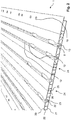
- the in Fig. 1 illustrated loading floor 1 of a vehicle comprises a plurality of elongate profile elements 2, 3, 4, 5, 6, 7, which are formed as edge elements 2, 7, intermediate elements 3, 6 and middle elements 4, 5.
- the two central elements 4, 5 are formed similar; Both intermediate elements 3, 6 are equal to each other.
- the edge elements 2, 7 are also the same except for the connection with the intermediate elements 3, 6.
- the profile elements 2, 3, 4, 5, 6, 7 are arranged side by side parallel to each other and connected to each other to the flat loading floor 1, which can be mounted on a floor plate or a support structure of a vehicle.
- a plurality of charging rails 8 are integrated in the upper side of the substantially smooth loading floor 1.
- Each loading rail 8 has an upwardly open longitudinal groove 9, which is narrowed in sections in the upper region by lateral projections 10 such that an inserted into the longitudinal groove 9, in Fig. 1 not shown sliding block can be removed only in the recesses 11 upwards.
- sections of the longitudinal groove 9 of the sliding block can be fixed for fixing a load, for example screwed or jammed.
- a plurality of holes 12 are arranged in the bottom of the longitudinal groove 9, which extend into the underlying, continuous elongated cavity 13 of the profile element 6 and a connection between the cavity 13 and the cargo space or passenger compartment of the vehicle, the bottom of the Loading floor 1 forms, manufacture.
- an air supply for supplying air conditioning air to the cavity 13 are connected, while at the rear end 15 of the cavity 13 can be closed, for example by a plug or by taking place during installation of the loading floor seal (not shown) , If now conveyed by an air conditioning system of the vehicle air conditioning air is introduced via a connected air conditioning air line into the cavity 13, so this air penetrates through the holes 12 and the longitudinal groove 9 in the located above the loading floor 1 interior of the vehicle and allows a particularly efficient air conditioning of the interior , which may be about a cargo compartment of a refrigerated transporter or a passenger compartment of the vehicle.
- the intermediate elements 3, 6 each have two longitudinal grooves 9 formed in this way, while the middle elements 4, 5 each comprise such a longitudinal groove 9.
- the cavities 16 of the edge elements 2, 7 are open through the holes 19 to the interior of the vehicle. These holes may have a larger diameter than the holes 12 in the longitudinal grooves 9, to an increased flow of air conditioning air in the edge region of the loading floor 1 and thus in the To ensure border area of this limited cargo or passenger space.
- an air conditioning air supply or an air conditioning air distributor can be connected to the cavities 16 of the edge elements 2, 7, while the rear ends of the cavities 16 can be closed.
- the further cavities 17, 18 of the intermediate or middle elements 3, 4, 5, 6, which have no openings to the interior of the vehicle, can be traversed by air conditioning air to the areas formed by the walls of the other cavities 17, 18 areas better to temper the loading floor according to the temperature of the air conditioning air.
- the other cavities 17, 18 can be connected at the end to air conditioning air lines.
- air is introduced from the front end face 14 of the loading floor into the other cavities 17, 18 having no lateral openings and is introduced into the bored cavities 13 by connecting lines which attach to the rear end face 15 of the loading floor 1. 16 are conducted, which are closed in this case at the front end 14. This allows optimal utilization of the air conditioning system provided by the air conditioning system of the vehicle.
- the profile elements 2, 3, 4, 5, 6, 7 respectively on its top and bottom a substantially smooth top structure 20 and substructure 21, wherein the substructure 21 for attachment to a support structure or on a floor panel of the vehicle is trained.
- Upper and lower structures 20, 21 are interconnected to increase the rigidity of the loading floor 1 by longitudinally continuous struts 22.
- the bottom of the longitudinal groove 9 can serve as between two struts 22 arranged further strut 23 to improve the stability of the loading floor.
- connection elements 24 can be seen, by which the profile elements 2, 3, 4, 5, 6, 7 are interconnected.
- connection elements 24 for producing a positive connection designed, for example, as lips 25, forming the locking grooves, engage in the latching projections 26.
- the loading floor 1 can be made from the profiled elements 2, 3, 4, 5, 6, 7 produced as extruded profiles, cut to length and provided with the bores 12, 19, for example by lateral assembly or by insertion in the longitudinal direction.
Description
Die Erfindung betrifft einen Ladeboden für ein Fahrzeug sowie ein Profilelement für einen derartigen Ladeboden.The invention relates to a loading floor for a vehicle and a profile element for such a loading floor.
Der Laderaum von Fahrzeugen ist in der Regel mit einem auf einer Bodenplatte oder einer Tragstruktur des Fahrzeugs befestigten Ladeboden versehen, der zur Vereinfachung der Beladung als im Wesentlichen ebene Fläche ausgebildet ist und die Last der Ladung aufnimmt. Ferner ist bei der Beladung von Fahrzeugen häufig die Aufgabe gestellt, Gegenstände sicher zu befestigen, so dass diese während der Fahrt am Fahrzeug fixiert sind. Hierfür weisen bekannte Ladeböden beispielsweise feststehende Ösen zur Aufnahme von Zurrgurten auf oder auch an Ladeschienen verschiebbare Befestigungselemente, die in eine Vielzahl von Positionen gebracht werden können und an denen beispielsweise Ösen für Zurrgurte angeordnet sind. Der Ladeboden kann aus einer Mehrzahl von Profilelementen zusammengesetzt sein, die derartige Ladeschienen aufweisen. Bei einigen Fahrzeugen ist auch eine wahlweise Benutzung als Laderaum oder als Passagierraum möglich. Dabei besteht die Möglichkeit, auf dem Ladeboden Sitze zu befestigen.The loading space of vehicles is usually provided with a loading floor fixed to a floor panel or supporting structure of the vehicle, which is designed to simplify the loading as a substantially flat surface and receives the load of the load. Furthermore, in the loading of vehicles is often the task of securely attaching objects so that they are fixed while driving on the vehicle. For this purpose, known loading floors, for example, fixed eyelets for receiving lashing or on loading rails sliding fasteners that can be placed in a variety of positions and where, for example, eyelets for lashing straps are arranged. The loading floor may be composed of a plurality of profile elements having such loading rails. In some vehicles, an optional use as a cargo space or as a passenger compartment is possible. It is possible to fix seats on the loading floor.
Aus der
Sowohl bei einer Verwendung eines derartigen Ladebodens zur Befestigung von Sitzen in einem für den Personentransport bestimmten Fahrzeug bzw. Bereich eines Fahrzeugs als auch bei einer Verwendung des Ladebodens in einem Laderaum eines Fahrzeugs besteht ein Bedarf an einer Klimatisierung des durch den Ladeboden begrenzten Raums. In der
Aus
In
In
Es ist Aufgabe der vorliegenden Erfindung, einen Ladeboden der genannten Art sowie ein Profilelement für einen Ladeboden anzugeben, wobei eine verbesserte Klimatisierung des durch den Ladeboden begrenzten Innenraums ermöglicht wird.It is an object of the present invention to provide a loading floor of the type mentioned as well as a profile element for a loading floor, wherein an improved air conditioning of the limited by the loading floor interior is made possible.
Diese Aufgabe wird durch einen Ladeboden sowie durch ein Profilelement für einen Ladeboden wie in den unabhängigen Ansprüchen angegeben gelöst.This object is achieved by a loading floor and by a profile element for a loading floor as specified in the independent claims.
Ein erfindungsgemäßer Ladeboden ist insbesondere für einen Lade- oder einen Passagierraum eines Fahrzeugs geeignet, kann aber auch beispielsweise als Wand- oder Deckenverkleidung in einem Fahrzeug eingesetzt werden. Der Ladeboden umfasst eine Mehrzahl von langerstreckten Profilelementen, die nebeneinander im Wesentlichen parallel zueinander angeordnet und miteinander verbunden sind.An inventive loading floor is particularly suitable for a loading or a passenger compartment of a vehicle, but can also be used for example as a wall or ceiling panel in a vehicle. The loading floor comprises a plurality of elongated profile elements, which are arranged side by side substantially parallel to each other and connected to each other.
Die Profilelemente sind vorzugsweise quer zu ihrer Längsrichtung formschlüssig miteinander verbunden, können aber auch beispielsweise reibschlüssig verbunden, verklebt und/oder verschweißt oder auf andere Weise miteinander verbunden sein. Vorzugsweise sind die Profilelemente durch Extrusion, beispielsweise als Aluminium-Strangpressprofile, hergestellt. Der Ladeboden kann neben den Profilelementen weitere Elemente umfassen, etwa endseitige Abdeckkappen oder Elemente zur Befestigung des Ladebodens auf einer Bodenplatte oder einer Tragstruktur des Fahrzeugs.The profile elements are preferably connected to each other transversely to their longitudinal direction positively, but can also, for example, frictionally connected, glued and / or welded or otherwise connected to each other. Preferably, the profile elements are produced by extrusion, for example as aluminum extruded profiles. The loading floor may comprise, in addition to the profile elements, further elements, such as end caps or elements for fastening the loading floor on a floor panel or a supporting structure of the vehicle.
Der erfindungsgemäße Ladeboden weist einen in der Längsrichtung der Profilelemente durchgehenden Hohlraum auf, der mindestens eine in der Längsrichtung nicht durchgehende seitliche Öffnung zu einem Außenraum des Ladebodens aufweist und im Übrigen seitlich geschlossen ist. Der Hohlraum kann stirnseitig offen sein, ist jedoch auf seinen übrigen Seiten bis auf die seitliche Öffnung abgeschlossen, die sich nur über einen Teil der Längserstreckung des Profilelements erstreckt, vorzugsweise über einen kleinen Teil. Die Öffnung kann beispielsweise als in das als Strangpressprofil hergestellte Profilelement eingebrachte Bohrung ausgebildet sein. Vorzugsweise weist mindestens eines der miteinander verbundenen Profilelemente einen derartigen Hohlraum auf, es ist jedoch auch möglich, dass ein solcher Hohlraum erst durch die Verbindung bzw. durch das Zusammenfügen von zwei oder mehr Profilelementen zum Aufbau des erfindungsgemäßen Ladebodens gebildet wird.The loading floor according to the invention has a continuous in the longitudinal direction of the profile elements cavity, which has at least one longitudinal opening not continuous in the longitudinal direction to an outside space of the loading floor and is otherwise closed laterally. The cavity may be open at the front, but is closed on its other sides except for the lateral opening, which extends only over part of the longitudinal extent of the profile element, preferably over a small part. The opening may for example be formed as introduced into the profile element produced as an extruded profile bore. Preferably, at least one of the interconnected profile elements such a cavity, but it is also possible that such a cavity is formed only by the connection or by the joining of two or more profile elements for the construction of the loading floor according to the invention.
Dadurch, dass der Ladeboden oder zumindest eines der Profilelemente, aus denen der Ladeboden zusammengesetzt ist, einen durchgehenden Hohlraum aufweist, der mindestens eine in der Längsrichtung der Profilelemente nicht durchgehende seitliche Öffnung aufweist und im Übrigen seitlich geschlossen ist, wird es ermöglicht, dass ein Klimatisierungsluftstrom, der durch den Hohlraum geleitet werden kann, aus dem Hohlraum austritt und dadurch in einen Außenraum des Profilelements bzw. des Ladebodens, nämlich in einen Innenraum des Fahrzeugs, gelangt. Hierdurch wird eine direkte Klimatisierung des von dem Ladeboden begrenzten Raums des Fahrzeugs ermöglicht. Insbesondere wird es hierdurch ermöglicht, erwärmte oder gekühlte und/oder auf einen bestimmten Feuchtigkeitsgehalt eingestellte Klimatisierungsluft in den durch den Ladeboden begrenzten Raum an einer durch die seitliche Öffnung bestimmten Position, die hinsichtlich der Klimatisierungswirkung optimal gewählt werden kann, gezielt einzuleiten. Dies gilt in besonderem Maße dann, wenn der Ladeboden nicht nur als Boden, sondern auch als Wand und/oder Decke eines Laderaums oder eines Passagierraums eines Fahrzeugs verwendet wird. So kann beispielsweise die Öffnung in einem in Längsrichtung mittleren Bereich des Ladebodens platziert sein, um eine optimale Einleitung der Klimatisierungsluft zu ermöglichen.Characterized in that the loading floor or at least one of the profile elements, of which the loading floor is composed, has a continuous cavity which has at least one not continuous in the longitudinal direction of the profile elements lateral opening and the rest is laterally closed, it is possible that an air conditioning air flow , which can be passed through the cavity, exiting the cavity and thereby enters an outer space of the profile element or the loading floor, namely in an interior of the vehicle. As a result, a direct air conditioning of the limited space of the load floor of the vehicle is made possible. In particular, this makes it possible to intentionally initiate conditioned or conditioned air conditioning air and / or adjusted to a certain moisture content in the space defined by the loading floor at a position determined by the lateral opening, which can be optimally selected with regard to the air conditioning effect. This is particularly true when the loading floor is used not only as a floor, but also as a wall and / or ceiling of a cargo space or a passenger compartment of a vehicle. Thus, for example, the opening may be placed in a longitudinally central region of the loading floor in order to allow optimum introduction of the air conditioning air.
Gemäß einer bevorzugten Ausführungsform der Erfindung wird der mindestens eine in der Längsrichtung durchgehende Hohlraum zwischen einer Oberstruktur eines Profilelements, einer Unterstruktur des Profilelements und/oder mindestens einer die Ober- und die Unterstruktur des Profilelements verbindenden Strebe ausgebildet. Die Ober- und die Unterstruktur können zur Ausbildung einer flachen Ober- bzw. Unterseite des Ladebodens eine im Wesentlichen ebene Ober- bzw. Unterseite aufweisen. Zur Erzielung einer hohen Steifigkeit des Ladebodens bei einem geringen Gewicht sind die Ober- und die Unterstruktur vorzugsweise voneinander beabstandet und durch mindestens eine Verstrebung miteinander verbunden. Die Verstrebung kann etwa durch eine oder mehrere senkrecht oder schräg zur Ober- bzw. Unterstruktur ausgebildete, in Längsrichtung des Profilelements durchgehende Streben gebildet werden. Durch einen derartigen Aufbau des Profilelementes werden ein oder mehrere durchgehende, seitlich geschlossene Hohlräume zwischen Oberstruktur, Unterstruktur und/oder Streben gebildet, die gemäß der bevorzugten Ausführungsform mit mindestens einer nicht durchgehenden seitlichen Öffnung in einen Außenraum versehen werden können. Hierdurch können etwa aus Stabilitäts- und Gewichtsgründen vorhandene Hohlräume der Profilelemente bzw. des Ladebodens zur Durchleitung von Klimatisierungsluft genutzt werden. Damit ist eine Verbesserung der Klimatisierung des Fahrzeuginnenraums mit minimalem Aufwand möglich.According to a preferred embodiment of the invention, the at least one hollow space extending in the longitudinal direction is formed between an upper structure of a profile element, a lower structure of the profile element and / or at least one strut connecting the upper and the lower structure of the profile element. The upper and the lower structure may have a substantially flat top or bottom to form a flat top or bottom of the loading floor. To achieve a high rigidity of the loading floor at a low weight, the upper and the lower structure are preferably spaced apart from each other and connected to each other by at least one strut. The strut can be formed for example by one or more vertically or obliquely to the top or bottom structure formed in the longitudinal direction of the profile element continuous struts. By such a construction of the profile element, one or more continuous, laterally closed cavities between the upper structure, substructure and / or struts are formed, which can be provided according to the preferred embodiment with at least one non-continuous lateral opening in an outer space. As a result, for example, for reasons of stability and weight existing cavities of the profile elements or the loading floor can be used for the passage of air conditioning air. For an improvement of the air conditioning of the vehicle interior with minimal effort is possible.
Vorzugsweise ist der Hohlraum zumindest in einem seiner beiden Endbereiche mit einer Klimatisierungsluftleitung verbindbar. Insbesondere kann der Hohlraum an mindestens einer der Stirnseiten des Ladebodens offen und derart ausgebildet sein, dass eine Klimatisierungsluftleitung zur Einleitung von Klimatisierungsluft in den Hohlraum anschließbar ist. An der anderen Stirnseite kann der Hohlraum ebenfalls offen sein, ist aber vorzugsweise verschlossen oder verschließbar. Hierdurch kann auf besonders einfache Weise von einem Klimatisierungssystem, etwa einer Klimaanlage des Fahrzeugs, bereitgestellte Klimatisierungsluft in den Hohlraum eingeleitet und durch den Hohlraum in den zu klimatisierenden Innenraum des Fahrzeugs eingeleitet werden.Preferably, the cavity is connectable to an air conditioning air duct at least in one of its two end regions. In particular, the cavity can be open on at least one of the front sides of the loading floor and designed such that an air conditioning air line for introducing air conditioning air into the cavity can be connected. On the other end face of the cavity may also be open, but is preferably closed or closed. As a result, air conditioning air provided in a particularly simple manner by an air-conditioning system, for example an air-conditioning system of the vehicle, can be introduced into the cavity and introduced through the cavity into the interior of the vehicle to be air-conditioned.
Weiterhin ist es bevorzugt, dass der Ladeboden mehrere durchgehende Hohlräume aufweist, die jeweils mindestens eine seitliche Öffnung zu einem Außenraum des Ladebodens haben können. Hierfür kann der Ladeboden mindestens ein Profilelement umfassen, das eine Mehrzahl derartiger Hohlräume aufweist und/oder der Ladeboden kann eine Mehrzahl von Profilelementen mit jeweils mindestens einem derartigen Hohlraum umfassen. Vorzugsweise sind die mehreren Hohlräume an mindestens einer Stirnseite des Ladebodens mit einem Klimatisierungsluftverteiler verbindbar, an den eine Klimatisierungsluftleitung zur Zuführung der Klimatisierungsluft in die mehreren Hohlräume anschließbar ist. Hierdurch kann eine besonders gleichmäßige Verteilung der Klimatisierungsluft durch Einleitung über mehrere Hohlräume in den an den Ladeboden angrenzenden Raum erreicht werden.Furthermore, it is preferred that the loading floor has a plurality of continuous cavities, which may each have at least one lateral opening to an outer space of the loading floor. For this purpose, the loading floor may comprise at least one profile element, which has a plurality of such cavities and / or the loading floor may comprise a plurality of profile elements, each having at least one such cavity. Preferably, the plurality of cavities are connectable on at least one end face of the loading floor with an air conditioning air distributor, to which an air conditioning air line for supplying the air conditioning air in the plurality of cavities can be connected. In this way, a particularly uniform distribution of the air conditioning air can be achieved by introducing over several cavities in the adjoining the loading floor space.
Gemäß einer weiteren bevorzugten Ausführungsform der Erfindung weist der Ladeboden mehrere Öffnungen auf, die vorzugsweise jeweils auf derselben Seite des Ladebodens angeordnet sind, nämlich auf der dem Innenraum des Fahrzeugs zugewandten Seite. Insbesondere kann ein Hohlraum eines Profilelements des Ladebodens mehrere Öffnungen aufweisen, die in Längsrichtung gegeneinander versetzt sind. Hierdurch kann eine weiter verbesserte Einleitung der Klimatisierungsluft in den Innenraum des Fahrzeugs erreicht werden.According to a further preferred embodiment of the invention, the loading floor has a plurality of openings, which are preferably each arranged on the same side of the loading floor, namely on the interior of the vehicle facing side. In particular, a cavity of a profile element of the loading floor may have a plurality of openings which are offset from one another in the longitudinal direction. In this way, a further improved introduction of the air conditioning air into the interior of the vehicle can be achieved.
Weiterhin ist es bevorzugt, dass die mehreren Öffnungen des Ladebodens bzw. des Profilelements des Ladebodens unterschiedliche Öffnungsweiten aufweisen. Hierdurch ist eine besonders gezielte und hochwirksame Einleitung von Klimatisierungsluft in den Innenraum des Fahrzeugs möglich.Furthermore, it is preferred that the plurality of openings of the loading floor or of the profile element of the loading floor have different opening widths. As a result, a particularly targeted and highly effective introduction of air conditioning air in the interior of the vehicle is possible.
So können beispielsweise die Öffnungsweiten mehrerer, in Längsrichtung gegeneinander versetzter Öffnungen eines Hohlraums eines Profilelements mit einem Abstand von einem Endbereich, in dem eine Klimatisierungsluftleitung oder ein Klimatisierungsluftverteiler an den Hohlraum anschließbar ist, zunehmen. Sind die Öffnungen beispielsweise als kreisförmige Bohrungen ausgeführt, so nimmt in diesem Fall der Durchmesser der Bohrungen mit dem Abstand von dem zum Verbinden mit der Klimatisierungsluftleitung bestimmten Endbereich zu. Insbesondere kann die Öffnungsweite derart zunehmen, dass sich für das Austreten der Klimatisierungsluft aus den einzelnen Öffnungen ein unter Berücksichtigung der unterschiedlichen Weglängen jeweils annähernd gleicher Strömungswiderstand ergibt. Hierdurch kann eine besonders gleichmäßige Verteilung der Klimatisierungsluft erreicht werden.Thus, for example, the opening widths of a plurality of longitudinally staggered openings of a cavity of a profile element with a distance from an end region in which an air conditioning air duct or an air conditioning air distributor can be connected to the cavity, increase. If the openings are designed, for example, as circular bores, in this case the diameter of the bores increases with the distance from the end region intended for connection to the air-conditioning air duct. In particular If the opening width can increase in such a way that for the exit of the air-conditioning air from the individual openings, an approximately identical flow resistance results taking into account the different path lengths. As a result, a particularly uniform distribution of the air conditioning air can be achieved.
Alternativ oder zusätzlich können die Öffnungen unterschiedlicher Hohlräume eines Profilelements und/oder die Öffnungen von Hohlräumen unterschiedlicher Profilelemente unterschiedliche Öffnungsweiten aufweisen. So können etwa die Öffnungen von Hohlräumen in Profilelementen, die den Randbereich des Ladebodens bilden, größer als die Öffnungen von Hohlräumen anderer Profilelemente sein. Es kann auch beispielsweise die Weite der in Längsrichtung gesehen jeweils ersten und/oder letzten Öffnung eines Hohlraums größer sein als die der übrigen Öffnungen desselben Hohlraums. Hierdurch kann die Einleitung von Klimatisierungsluft dem zu klimatisierenden Raum optimal angepasst werden, indem eine verstärkte Einleitung von Klimatisierungsluft im Rand- bzw. wandnahen Bereich eines Innenraums des Fahrzeugs erfolgt. Auch hierdurch kann eine gleichmäßigere Klimatisierung des Innenraums erreicht werden.Alternatively or additionally, the openings of different cavities of a profile element and / or the openings of cavities of different profile elements may have different opening widths. For example, the openings of cavities in profile elements which form the edge region of the loading floor can be larger than the openings of cavities of other profile elements. It is also possible, for example, for the width of the first and / or last opening of a cavity seen in the longitudinal direction to be greater than that of the remaining openings of the same cavity. In this way, the introduction of air conditioning air can be optimally adapted to the room to be conditioned by an increased introduction of air conditioning air in the edge or near-wall area of an interior of the vehicle takes place. This also allows a more uniform air conditioning of the interior can be achieved.
Vorzugsweise weist mindestens ein Profilelement des Ladebodens mehrere sich in Längsrichtung erstreckende Hohlräume auf, die miteinander durch mindestens einen Durchbruch in einer die Hohlräume trennenden Trennwand, etwa einer durchgehenden Strebe, verbunden sind. Die mehreren Hohlräume weisen jeweils eine oder mehrere seitliche Öffnungen zum Außenraum des Ladebodens auf. Vorzugsweise ist mindestens einer der mehreren Hohlräume des Profilelements stirnseitig verschließbar oder verschlossen und steht mit einem anderen Hohlraum, in den stirnseitig Klimatisierungsluft eingeleitet werden kann, in Verbindung. Hierdurch kann auf einfache Weise eine besonders gleichmäßige Verteilung der Klimatisierungsluft erreicht werden.Preferably, at least one profile element of the loading floor has a plurality of longitudinally extending cavities, which are connected to each other by at least one breakthrough in a dividing wall separating the cavities, such as a continuous strut. The plurality of cavities each have one or more lateral openings to the exterior of the loading floor. Preferably, at least one of the plurality of cavities of the profile element can be closed or closed at the end side and communicates with another cavity into which air conditioning air can be introduced at the front side. As a result, a particularly uniform distribution of the air conditioning air can be achieved in a simple manner.
Gemäß einer besonders bevorzugten Ausführungsform Erfindungsgemäß weist mindestens ein Profilelement eine Längsnut auf, wobei die seitliche Öffnung des Hohlraums in der Längsnut mündet. Die Längsnut ist insbesondere zu einer Oberseite des Profilelements, d.h. zum Innenraum des Fahrzeugs, offen. Die Längsnut kann beispielsweise als Längsnut einer Ladeschiene ausgebildet sein, in der ein Gleitstein verschiebbar geführt ist, oder das Profilelement kann auch selbst als Ladeschiene ausgebildet sein. Dadurch, dass die durch den Hohlraum des Profilelements eingeleitete Klimatisierungsluft durch die in der Längsnut mündende Öffnung austreten kann, wird erreicht, dass die Öffnung nicht durch ein darauf aufliegendes Ladegut verschlossen werden kann und unabhängig von der Position eines solchen Ladeguts eine Zuführung der Klimatisierungsluft in den durch den Ladeboden begrenzten Raum, insbesondere einen Laderaum des Fahrzeugs, möglich ist. Ferner wird es auf diese Weise erleichtert, zwischen den Längsnuten auf der Oberseite des Ladebodens einen Teppich oder eine reibungserhöhende Auflage aufzubringen, ohne dadurch die Öffnungen zur Einleitung von Klimatisierungsluft in den Innenraum des Fahrzeugs zu verdecken.According to a particularly preferred embodiment according to the invention, at least one profile element has a longitudinal groove, wherein the lateral opening of the cavity opens into the longitudinal groove. The longitudinal groove is in particular to an upper side of the profile element, ie the interior of the vehicle, open. The longitudinal groove may for example be formed as a longitudinal groove of a charging rail, in which a sliding block is displaceably guided, or the profile element may also be formed itself as a charging rail. The fact that the introduced through the cavity of the profile element air conditioning air can escape through the opening in the longitudinal groove opening, it is achieved that the opening can not be closed by a load lying thereon and regardless of the position of such cargo feeding the air conditioning in the through the loading floor limited space, in particular a cargo space of the vehicle, is possible. Furthermore, in this way it is facilitated to apply a carpet or a friction-increasing pad between the longitudinal grooves on the top of the loading floor, without thereby covering the openings for the introduction of air conditioning air into the interior of the vehicle.
Vorzugsweise ist die mindestens eine Öffnung in einem Seitenbereich der Längsnut angeordnet. Hierdurch kann eine Verschmutzung und ein möglicher Verschluss der Öffnung durch Verschmutzung besonders sicher vermieden werden. Die mindestens eine Öffnung kann aber auch im Bodenbereich der Längsnut angeordnet sein, wodurch die Herstellung des Profilelements und das Einbringen der Bohrungen erleichtert wird.Preferably, the at least one opening is arranged in a side region of the longitudinal groove. As a result, contamination and a possible closure of the opening due to contamination can be avoided particularly reliably. The at least one opening can also be arranged in the bottom region of the longitudinal groove, whereby the production of the profile element and the introduction of the holes is facilitated.
Ein erfindungsgemäßes Profilelement für einen Ladeboden eines Fahrzeugs weist einen Hohlraum auf, der sich in einer Längsrichtung des Profilelements erstreckt und von einem zum anderen Ende des Profilelements durchgehend ausgebildet ist. Der Hohlraum weist mindestens eine in der Längsrichtung nicht durchgehende seitliche Öffnung zu einem Außenraum des Profilelements auf und ist im Übrigen seitlich abgeschlossen. Das Profilelement kann ferner Anschlusselemente umfassen, die beispielsweise als Rastvorsprünge und Rastnuten ausgebildet sein können, zur Verbindung mit weiteren Profilelementen, um aus den Profilelementen einen Ladeboden zusammenzusetzen. Insbesondere kann das Profilelement ausgebildet sein, um durch Verbindung mit weiteren Profilelementen einen Ladeboden der oben beschriebenen Art herzustellen.An inventive profile element for a loading floor of a vehicle has a cavity which extends in a longitudinal direction of the profile element and is formed continuously from one to the other end of the profile element. The cavity has at least one lateral opening, which is not continuous in the longitudinal direction, to an outer space of the profile element and, moreover, is laterally closed. The profile element can further comprise connecting elements, which may be formed, for example, as locking projections and locking grooves, for connection to further profile elements in order to assemble a loading floor from the profile elements. In particular, the profile element can be designed to produce a load floor of the type described above by connection with other profile elements.
Die Erfindung wird nachfolgend anhand der Zeichnungen beispielhaft näher erläutert. Es zeigen:
- Fig. 1
- ein Ausführungsbeispiel eines erfindungsgemäßen Ladebodens in perspektivischer Ansicht;
- Fig. 2
- einen Teil des Ausführungsbeispiels gemäß
Fig. 1 in vergrößerter perspektivischer Ansicht.
- Fig. 1
- an embodiment of a loading floor according to the invention in a perspective view;
- Fig. 2
- a part of the embodiment according to
Fig. 1 in enlarged perspective view.
Der in
Wie in
Entlang der Längserstreckung des Zwischenelements 6 sind im Boden der Längsnut 9 eine Mehrzahl an Bohrungen 12 angeordnet, die in den darunterliegenden, durchgehenden längserstreckten Hohlraum 13 des Profilelements 6 reichen und eine Verbindung zwischen dem Hohlraum 13 und dem Laderaum oder Passagierraum des Fahrzeugs, dessen Boden der Ladeboden 1 bildet, herstellen. An einem vorderen Stirnende 14 des Ladebodens 1 kann eine Luftzuführung zur Zuführung von Klimatisierungsluft an den Hohlraum 13 angeschlossen werden, während am hinteren Stirnende 15 der Hohlraum 13 beispielsweise durch einen Stopfen oder durch eine beim Einbau des Ladebodens erfolgende Abdichtung verschlossen werden kann (nicht dargestellt). Wird nun von einem Klimatisierungssystem des Fahrzeugs geförderte Klimatisierungsluft über eine angeschlossene Klimatisierungsluftleitung in den Hohlraum 13 eingeleitet, so dringt diese Luft durch die Bohrungen 12 und die Längsnut 9 in den über dem Ladeboden 1 befindlichen Innenraum des Fahrzeugs ein und ermöglicht eine besonders effiziente Klimatisierung des Innenraums, der etwa ein Laderaum eines Kühltransporters oder auch ein Passagierraum des Fahrzeugs sein kann. Die Zwischenelemente 3, 6 weisen im dargestellten Ausführungsbeispiel jeweils zwei derart ausgebildete Längsnuten 9 auf, während die Mittelelemente 4, 5 jeweils eine solche Längsnut 9 umfassen.Along the longitudinal extent of the intermediate element 6 a plurality of
Die Hohlräume 16 der Randelemente 2, 7 sind durch die Bohrungen 19 zum Innenraum des Fahrzeugs hin offen. Diese Bohrungen können einen größeren Durchmesser als die Bohrungen 12 in den Längsnuten 9 aufweisen, um einen erhöhten Durchstrom von Klimatisierungsluft im Randbereich des Ladebodens 1 und damit im Randbereich des durch diesen begrenzten Lade- oder Passagierraums zu gewährleisten. Am vorderen Stirnende 14 des Ladebodens 1 kann eine Klimatisierungsluftzuführung oder ein Klimatisierungsluftverteiler an die Hohlräume 16 der Randelemente 2, 7 angeschlossen werden, während die hinteren Enden der Hohlräume 16 verschlossen werden können.The
Auch die weiteren Hohlräume 17, 18 der Zwischen- bzw. Mittelelemente 3, 4, 5, 6, die keine Öffnungen zum Innenraum des Fahrzeugs aufweisen, können mit Klimatisierungsluft durchströmbar sein, um auch die von den Wänden der weiteren Hohlräume 17, 18 gebildeten Bereiche des Ladebodens entsprechend der Temperatur der Klimatisierungsluft besser zu temperieren. Hierfür können die weiteren Hohlräume 17, 18 endseitig mit Klimatisierungsluftleitungen verbunden werden. So kann es beispielsweise vorgesehen sein, dass in die keine seitlichen Öffnungen aufweisenden weiteren Hohlräume 17, 18 Luft vom vorderen Stirnende 14 des Ladebodens eingeleitet wird und durch Verbindungsleitungen, die am hinteren Stirnende 15 des Ladebodens 1 ansetzen, in die mit Bohrungen versehenen Hohlräume 13, 16 geleitet werden, die in diesem Fall am vorderen Stirnende 14 verschlossen sind. Hierdurch wird eine optimale Ausnutzung der vom Klimatisierungssystem des Fahrzeugs bereitgestellten Klimatisierungsluft ermöglicht.The
Wie in der vergrößerten Darstellung der
In
Der Übersichtlichkeit halber sind nicht in allen Figuren alle Bezugszeichen dargestellt. Im Text nicht erläuterte Bezugszeichen haben die gleiche Bedeutung wie in den übrigen Figuren.For clarity, not all figures are shown in all figures. In the text not explained reference numerals have the same meaning as in the other figures.
- 11
- Ladebodenload floor
- 22
- RandelementBoundary element
- 33
- Zwischenelementintermediate element
- 44
- Mittelelementmiddle element
- 55
- Mittelelementmiddle element
- 66
- Zwischenelementintermediate element
- 77
- RandelementBoundary element
- 88th
- Ladeschienecharging rail
- 99
- Längsnutlongitudinal groove
- 1010
- Vorsprunghead Start
- 1111
- Aussparungrecess
- 1212
- Bohrungdrilling
- 1313
- Hohlraumcavity
- 1414
- Stirnendefront end
- 1515
- Stirnendefront end
- 1616
- Hohlraumcavity
- 1717
- Hohlraumcavity
- 1818
- Hohlraumcavity
- 1919
- Bohrungdrilling
- 2020
- Oberstruktursuperstructure
- 2121
- Unterstruktursubstructure
- 2222
- Strebestrut
- 2323
- Strebestrut
- 2424
- Anschlusselementconnecting element
- 2525
- Lippelip
- 2626
- Rastvorsprungcatch projection
Claims (9)
- Loading floor for a vehicle, comprising a plurality of profile members which are elongate in a longitudinal direction, which are arranged beside each other and which are connected to each other, in which the loading floor (1) has at least one hollow space (13, 16) which is continuous in the longitudinal direction,
characterized in that
the hollow space (13, 16) has at least one lateral opening (12, 19), which is not continuous in the longitudinal direction, with respect to an outer space of the loading floor and which is further laterally closed, so that an air conditioning air stream which can be directed through the hollow space (13, 16) is discharged from the hollow space (13, 16) and thereby reaches an inner space of the vehicle, wherein at least one profile member has a longitudinal groove (9) and wherein the lateral opening (12) of the hollow space (13) of the profile member that is continuous in the longitudinal direction opens in the longitudinal groove (9). - Loading floor according to Claim 1,
characterized in that
the at least one hollow space (13, 16) which is continuous in the longitudinal direction is constructed between an upper structure (20), a lower structure (21) and/or at least one strut (22, 23) which connects the upper and lower structure (20, 21) of a profile member. - Loading floor according to Claim 1 or Claim 2, cha
racterized in that
the hollow space (13, 16) can be connected to an air conditioning air line in a front and/or a rear end region. - Loading floor according to one of the preceding claims,
characterized in that
the loading floor (1) has a plurality of hollow spaces (13, 16) which are continuous in the longitudinal direction and which can be connected to an air conditioning air distributor at least at one end face of the loading floor (1). - Loading floor according to one of the preceding claims,
characterized in that
the loading floor (1) has a plurality of lateral openings (12, 19) which are directed in particular to the same side of the loading floor (1). - Loading floor according to the preceding claim, cha
racterized in that
the openings (12, 19) have different opening widths. - Loading floor according to one of the preceding claims,
characterized in that
at least one profile member has a plurality of hollow spaces which extend in the longitudinal direction and which are connected to each other by means of at least one aperture in a partition wall. - Loading floor according to one of the preceding claims,
characterized in that
the openings (12) open in a bottom region and/or in a lateral region of the longitudinal groove (9). - Profile member for a loading floor of a vehicle, wherein the profile member has a continuous hollow space (13, 16) which extends in a longitudinal direction of the profile member,
characterized in that
the hollow space (13, 16) has at least one lateral opening (12, 19), which is not continuous in the longitudinal direction, with respect to an outer space of the profile member and which is further laterally closed, and in that the profile member has a longitudinal groove (9), wherein the lateral opening (12) of the hollow space (13) of the profile member that is continuous in the longitudinal direction opens in the longitudinal groove (9).
Applications Claiming Priority (1)
| Application Number | Priority Date | Filing Date | Title |
|---|---|---|---|
| DE102012204713A DE102012204713A1 (en) | 2012-03-23 | 2012-03-23 | Loading floor and profile element for a loading floor |
Publications (3)
| Publication Number | Publication Date |
|---|---|
| EP2641817A2 EP2641817A2 (en) | 2013-09-25 |
| EP2641817A3 EP2641817A3 (en) | 2015-10-28 |
| EP2641817B1 true EP2641817B1 (en) | 2019-08-07 |
Family
ID=47900656
Family Applications (1)
| Application Number | Title | Priority Date | Filing Date |
|---|---|---|---|
| EP13158084.7A Active EP2641817B1 (en) | 2012-03-23 | 2013-03-07 | Loading floor and profiled element for a loading floor |
Country Status (4)
| Country | Link |
|---|---|
| US (1) | US20130252529A1 (en) |
| EP (1) | EP2641817B1 (en) |
| CN (1) | CN103318268B (en) |
| DE (1) | DE102012204713A1 (en) |
Families Citing this family (10)
| Publication number | Priority date | Publication date | Assignee | Title |
|---|---|---|---|---|
| DE202013104738U1 (en) * | 2013-10-21 | 2015-01-22 | Hermann Greshake | Device for regulating the temperature of cargo compartments of small transporters |
| GB2537640A (en) * | 2015-04-21 | 2016-10-26 | Lindberg Global Ltd | A vehicle flooring system |
| US9637026B2 (en) | 2015-05-28 | 2017-05-02 | Freedman Seating Company | Floor tile system for mounting vehicle seats and methods for mounting vehicle seats |
| BE1024958B1 (en) * | 2016-06-02 | 2018-08-30 | Mercury Trading Bvba | Improved space connecting device for passenger transport means |
| US9944334B1 (en) * | 2017-05-10 | 2018-04-17 | Ancra International Llc | Inner wall system for cargo container |
| GB201620959D0 (en) * | 2016-12-09 | 2017-01-25 | Adams William M | Improvements to goods storage trailers |
| AT519023B1 (en) | 2017-03-24 | 2018-03-15 | Rosenbauer Int Ag | Cab module and thus equipped motor vehicle |
| US10919612B2 (en) * | 2018-03-08 | 2021-02-16 | The Boeing Company | Floor panels and flooring systems for a passenger vehicle, and methods for installation |
| US11332197B2 (en) | 2018-10-12 | 2022-05-17 | Zephyros, Inc. | Composite load bearing flooring |
| US11919361B2 (en) | 2022-03-21 | 2024-03-05 | Ford Global Technologies, Llc | Vehicle floor panel |
Family Cites Families (26)
| Publication number | Priority date | Publication date | Assignee | Title |
|---|---|---|---|---|
| US2040296A (en) * | 1934-01-24 | 1936-05-12 | Charles O Cornwell | Insulated car with air circulating chamber |
| US2184113A (en) * | 1935-03-05 | 1939-12-19 | Annunziata Calafati | Building construction |
| US2195691A (en) * | 1939-06-30 | 1940-04-02 | Fred C Burt | Floor heater |
| US2696774A (en) * | 1950-01-12 | 1954-12-14 | Gen Motors Corp | Automobile heating and ventilating system |
| US3092220A (en) * | 1959-12-03 | 1963-06-04 | Pullman Inc | Floor construction for refrigerated roadway vehicle |
| US3246592A (en) * | 1963-08-28 | 1966-04-19 | Rath Company | Air conditioning for vehicle of lading |
| US3416280A (en) * | 1965-10-05 | 1968-12-17 | Revere Copper & Brass Inc | Contoured insert support for upstanding i-beam elements of a cargo-supporting floor |
| US3453839A (en) * | 1967-10-26 | 1969-07-08 | Alfred B Sabin | Cargo transport system and container therefor |
| US3733849A (en) * | 1971-06-29 | 1973-05-22 | Sun Shipbuilding & Dry Dock Co | Apparatus for transportation of commodities |
| US3877671A (en) | 1972-03-06 | 1975-04-15 | Hughes Aircraft Co | Unitary tie-down panel apparatus |
| NL7608639A (en) * | 1976-08-03 | 1978-02-07 | Pakhoed Rotterdam Bv | CHEST EQUIPPED WITH IMPROVED FLOOR CONSTRUCTION. |
| SU753684A1 (en) * | 1977-12-07 | 1980-08-07 | Предприятие П/Я А-7449 | Apparatus for heating vehicle interior |
| US4446805A (en) * | 1981-06-25 | 1984-05-08 | Reefer Express Lines Pty., Ltd. | Deck construction for refrigerated cargo ships |
| AU573457B2 (en) * | 1986-10-21 | 1988-06-09 | Nippon Light Metal Company Ltd. | Refrigerated transport |
| GB2353769A (en) | 1999-09-01 | 2001-03-07 | Michael Angelo Callard | Vehicle flooring system |
| WO2001038127A1 (en) | 1999-11-26 | 2001-05-31 | Graham Hardman | Flooring for a vehicle and seating attached thereto |
| US6736442B2 (en) * | 2001-11-30 | 2004-05-18 | Collins & Aikman Products & Co. | Floor coverings for vehicles having integrated air and lighting distribution |
| DE10251945B3 (en) * | 2002-11-08 | 2004-03-04 | Daimlerchrysler Ag | Chassis and/or support structure for a motor vehicle, especially a car, comprises a hollow chamber plate structure designed as a channel system for aeration/ventilation of a passenger compartment |
| DK1701860T3 (en) | 2003-10-22 | 2007-12-10 | Beheers & Beleggingsmij Verach | Improved floor mounted on the bottom of transport vehicles for securing chairs / seats and wheelchairs |
| DK200500158U4 (en) | 2005-07-04 | 2006-07-28 | Handi Mobil Holding Aps | A floor plate for a vehicle |
| US7585208B2 (en) * | 2007-02-13 | 2009-09-08 | Dole Food Company, Inc. | Baffle plate assembly for directing air flow in a cargo container |
| DE502008003386D1 (en) * | 2007-12-04 | 2011-06-09 | Marsk Container Ind As | Container mit leitwand |
| US20100237157A1 (en) * | 2009-03-21 | 2010-09-23 | Zhaojun Guo | Ground heating flooring with internal heating conduction structure |
| WO2010147797A2 (en) * | 2009-06-19 | 2010-12-23 | Carrier Corporation | Temperature-controlled cargo container with air distribution |
| DE102012212305B4 (en) | 2011-07-18 | 2024-03-28 | Ford-Werke Gmbh | Loading floor and method for producing a loading floor |
| DE202011051401U1 (en) * | 2011-07-18 | 2011-11-17 | Ford-Werke Gmbh | load floor |
-
2012
- 2012-03-23 DE DE102012204713A patent/DE102012204713A1/en not_active Withdrawn
-
2013
- 2013-03-07 EP EP13158084.7A patent/EP2641817B1/en active Active
- 2013-03-18 CN CN201310086313.9A patent/CN103318268B/en not_active Expired - Fee Related
- 2013-03-20 US US13/848,024 patent/US20130252529A1/en not_active Abandoned
Non-Patent Citations (1)
| Title |
|---|
| None * |
Also Published As
| Publication number | Publication date |
|---|---|
| US20130252529A1 (en) | 2013-09-26 |
| EP2641817A3 (en) | 2015-10-28 |
| CN103318268B (en) | 2017-12-19 |
| DE102012204713A1 (en) | 2013-09-26 |
| EP2641817A2 (en) | 2013-09-25 |
| CN103318268A (en) | 2013-09-25 |
Similar Documents
| Publication | Publication Date | Title |
|---|---|---|
| EP2641817B1 (en) | Loading floor and profiled element for a loading floor | |
| EP2641777A2 (en) | Loading floor and profiled element for a loading floor | |
| DE102012212305B4 (en) | Loading floor and method for producing a loading floor | |
| EP2583914B1 (en) | Floor construction | |
| WO2012110045A1 (en) | Longitudinal support for the transition region from a coach body side wall to the coach body roof of a rail vehicle coach body | |
| DE69831092T2 (en) | FLOOR FOR TRANSPORT AND FLAT PROFILES FOR ITS ASSEMBLY, AND VEHICLE EQUIPPED WITH SUCH A FLOOR | |
| DE102006014719B4 (en) | Carrier profile and mounting arrangement of a seat underframe on a ground system of a bus | |
| EP0489294A1 (en) | Body for railway vehicles | |
| DE4128234C1 (en) | ||
| EP1285837A1 (en) | Framework of the bodyshell of a vehicle | |
| DE2927640A1 (en) | INTERIOR COVERING FOR THE CEILING AREA OF VEHICLES | |
| DE102008024634A1 (en) | Motorhome or caravan with warm air thermo floor | |
| DE2502453C3 (en) | Link radiator made of aluminum for central heating systems | |
| DE19628305A1 (en) | Rail vehicle | |
| DE7333031U (en) | VEHICLE BODY IN PARTICULAR FOR TOURIST BUSES | |
| WO2014154441A1 (en) | Assembly device for a side wall cladding element of a rail vehicle | |
| DE102010048863A1 (en) | Base frame for motor vehicle body, has multiple hollow carriers and base plates extended between carriers, where air duct is guided for air supply to passenger space inside one of carriers | |
| DE102006023169B4 (en) | Component for a commercial vehicle body, commercial vehicle with such a component and method for producing such a component | |
| EP3695999A1 (en) | Luggage structure for a commercial vehicle | |
| DE3424690C2 (en) | Self-supporting bus body | |
| DE202004014468U1 (en) | Profile for mounting wall element and/or floor element and/or roof element of vehicle structure has additional formation forming additional functional device; additional formation is further wall and/or floor and/or roof element support | |
| EP3388317A1 (en) | Refrigeration vehicle structure | |
| EP3718849B1 (en) | Rail vehicle and use | |
| EP1512466A1 (en) | Booth for surface treatment of workpieces | |
| DE2634712C2 (en) | Air duct for heating and / or ventilating the interior of motor vehicles, in particular buses |
Legal Events
| Date | Code | Title | Description |
|---|---|---|---|
| PUAI | Public reference made under article 153(3) epc to a published international application that has entered the european phase |
Free format text: ORIGINAL CODE: 0009012 |
|
| AK | Designated contracting states |
Kind code of ref document: A2 Designated state(s): AL AT BE BG CH CY CZ DE DK EE ES FI FR GB GR HR HU IE IS IT LI LT LU LV MC MK MT NL NO PL PT RO RS SE SI SK SM TR |
|
| AX | Request for extension of the european patent |
Extension state: BA ME |
|
| PUAL | Search report despatched |
Free format text: ORIGINAL CODE: 0009013 |
|
| AK | Designated contracting states |
Kind code of ref document: A3 Designated state(s): AL AT BE BG CH CY CZ DE DK EE ES FI FR GB GR HR HU IE IS IT LI LT LU LV MC MK MT NL NO PL PT RO RS SE SI SK SM TR |
|
| AX | Request for extension of the european patent |
Extension state: BA ME |
|
| RIC1 | Information provided on ipc code assigned before grant |
Ipc: B62D 21/17 20060101ALI20150923BHEP Ipc: B62D 25/20 20060101AFI20150923BHEP Ipc: B62D 33/04 20060101ALN20150923BHEP Ipc: B60H 1/24 20060101ALI20150923BHEP |
|
| 17P | Request for examination filed |
Effective date: 20160428 |
|
| RBV | Designated contracting states (corrected) |
Designated state(s): AL AT BE BG CH CY CZ DE DK EE ES FI FR GB GR HR HU IE IS IT LI LT LU LV MC MK MT NL NO PL PT RO RS SE SI SK SM TR |
|
| RIC1 | Information provided on ipc code assigned before grant |
Ipc: B62D 25/20 20060101AFI20181009BHEP Ipc: B62D 33/04 20060101ALN20181009BHEP Ipc: B62D 21/17 20060101ALI20181009BHEP Ipc: B60H 1/24 20060101ALI20181009BHEP |
|
| RIC1 | Information provided on ipc code assigned before grant |
Ipc: B62D 25/20 20060101AFI20181113BHEP Ipc: B62D 21/17 20060101ALI20181113BHEP Ipc: B60H 1/24 20060101ALI20181113BHEP Ipc: B62D 33/04 20060101ALN20181113BHEP |
|
| GRAP | Despatch of communication of intention to grant a patent |
Free format text: ORIGINAL CODE: EPIDOSNIGR1 |
|
| STAA | Information on the status of an ep patent application or granted ep patent |
Free format text: STATUS: GRANT OF PATENT IS INTENDED |
|
| INTG | Intention to grant announced |
Effective date: 20190107 |
|
| RIC1 | Information provided on ipc code assigned before grant |
Ipc: B62D 33/04 20060101ALN20181217BHEP Ipc: B62D 25/20 20060101AFI20181217BHEP Ipc: B60H 1/24 20060101ALI20181217BHEP Ipc: B62D 21/17 20060101ALI20181217BHEP |
|
| GRAS | Grant fee paid |
Free format text: ORIGINAL CODE: EPIDOSNIGR3 |
|
| GRAA | (expected) grant |
Free format text: ORIGINAL CODE: 0009210 |
|
| STAA | Information on the status of an ep patent application or granted ep patent |
Free format text: STATUS: THE PATENT HAS BEEN GRANTED |
|
| AK | Designated contracting states |
Kind code of ref document: B1 Designated state(s): AL AT BE BG CH CY CZ DE DK EE ES FI FR GB GR HR HU IE IS IT LI LT LU LV MC MK MT NL NO PL PT RO RS SE SI SK SM TR |
|
| REG | Reference to a national code |
Ref country code: GB Ref legal event code: FG4D Free format text: NOT ENGLISH |
|
| REG | Reference to a national code |
Ref country code: CH Ref legal event code: EP Ref country code: AT Ref legal event code: REF Ref document number: 1163418 Country of ref document: AT Kind code of ref document: T Effective date: 20190815 |
|
| REG | Reference to a national code |
Ref country code: DE Ref legal event code: R096 Ref document number: 502013013294 Country of ref document: DE |
|
| REG | Reference to a national code |
Ref country code: IE Ref legal event code: FG4D Free format text: LANGUAGE OF EP DOCUMENT: GERMAN |
|
| REG | Reference to a national code |
Ref country code: NL Ref legal event code: MP Effective date: 20190807 |
|
| REG | Reference to a national code |
Ref country code: LT Ref legal event code: MG4D |
|
| PG25 | Lapsed in a contracting state [announced via postgrant information from national office to epo] |
Ref country code: HR Free format text: LAPSE BECAUSE OF FAILURE TO SUBMIT A TRANSLATION OF THE DESCRIPTION OR TO PAY THE FEE WITHIN THE PRESCRIBED TIME-LIMIT Effective date: 20190807 Ref country code: BG Free format text: LAPSE BECAUSE OF FAILURE TO SUBMIT A TRANSLATION OF THE DESCRIPTION OR TO PAY THE FEE WITHIN THE PRESCRIBED TIME-LIMIT Effective date: 20191107 Ref country code: NL Free format text: LAPSE BECAUSE OF FAILURE TO SUBMIT A TRANSLATION OF THE DESCRIPTION OR TO PAY THE FEE WITHIN THE PRESCRIBED TIME-LIMIT Effective date: 20190807 Ref country code: LT Free format text: LAPSE BECAUSE OF FAILURE TO SUBMIT A TRANSLATION OF THE DESCRIPTION OR TO PAY THE FEE WITHIN THE PRESCRIBED TIME-LIMIT Effective date: 20190807 Ref country code: PT Free format text: LAPSE BECAUSE OF FAILURE TO SUBMIT A TRANSLATION OF THE DESCRIPTION OR TO PAY THE FEE WITHIN THE PRESCRIBED TIME-LIMIT Effective date: 20191209 Ref country code: SE Free format text: LAPSE BECAUSE OF FAILURE TO SUBMIT A TRANSLATION OF THE DESCRIPTION OR TO PAY THE FEE WITHIN THE PRESCRIBED TIME-LIMIT Effective date: 20190807 Ref country code: NO Free format text: LAPSE BECAUSE OF FAILURE TO SUBMIT A TRANSLATION OF THE DESCRIPTION OR TO PAY THE FEE WITHIN THE PRESCRIBED TIME-LIMIT Effective date: 20191107 Ref country code: FI Free format text: LAPSE BECAUSE OF FAILURE TO SUBMIT A TRANSLATION OF THE DESCRIPTION OR TO PAY THE FEE WITHIN THE PRESCRIBED TIME-LIMIT Effective date: 20190807 |
|
| PG25 | Lapsed in a contracting state [announced via postgrant information from national office to epo] |
Ref country code: IS Free format text: LAPSE BECAUSE OF FAILURE TO SUBMIT A TRANSLATION OF THE DESCRIPTION OR TO PAY THE FEE WITHIN THE PRESCRIBED TIME-LIMIT Effective date: 20191207 Ref country code: RS Free format text: LAPSE BECAUSE OF FAILURE TO SUBMIT A TRANSLATION OF THE DESCRIPTION OR TO PAY THE FEE WITHIN THE PRESCRIBED TIME-LIMIT Effective date: 20190807 Ref country code: ES Free format text: LAPSE BECAUSE OF FAILURE TO SUBMIT A TRANSLATION OF THE DESCRIPTION OR TO PAY THE FEE WITHIN THE PRESCRIBED TIME-LIMIT Effective date: 20190807 Ref country code: GR Free format text: LAPSE BECAUSE OF FAILURE TO SUBMIT A TRANSLATION OF THE DESCRIPTION OR TO PAY THE FEE WITHIN THE PRESCRIBED TIME-LIMIT Effective date: 20191108 Ref country code: AL Free format text: LAPSE BECAUSE OF FAILURE TO SUBMIT A TRANSLATION OF THE DESCRIPTION OR TO PAY THE FEE WITHIN THE PRESCRIBED TIME-LIMIT Effective date: 20190807 Ref country code: LV Free format text: LAPSE BECAUSE OF FAILURE TO SUBMIT A TRANSLATION OF THE DESCRIPTION OR TO PAY THE FEE WITHIN THE PRESCRIBED TIME-LIMIT Effective date: 20190807 |
|
| PG25 | Lapsed in a contracting state [announced via postgrant information from national office to epo] |
Ref country code: TR Free format text: LAPSE BECAUSE OF FAILURE TO SUBMIT A TRANSLATION OF THE DESCRIPTION OR TO PAY THE FEE WITHIN THE PRESCRIBED TIME-LIMIT Effective date: 20190807 |
|
| PG25 | Lapsed in a contracting state [announced via postgrant information from national office to epo] |
Ref country code: DK Free format text: LAPSE BECAUSE OF FAILURE TO SUBMIT A TRANSLATION OF THE DESCRIPTION OR TO PAY THE FEE WITHIN THE PRESCRIBED TIME-LIMIT Effective date: 20190807 Ref country code: EE Free format text: LAPSE BECAUSE OF FAILURE TO SUBMIT A TRANSLATION OF THE DESCRIPTION OR TO PAY THE FEE WITHIN THE PRESCRIBED TIME-LIMIT Effective date: 20190807 Ref country code: IT Free format text: LAPSE BECAUSE OF FAILURE TO SUBMIT A TRANSLATION OF THE DESCRIPTION OR TO PAY THE FEE WITHIN THE PRESCRIBED TIME-LIMIT Effective date: 20190807 Ref country code: RO Free format text: LAPSE BECAUSE OF FAILURE TO SUBMIT A TRANSLATION OF THE DESCRIPTION OR TO PAY THE FEE WITHIN THE PRESCRIBED TIME-LIMIT Effective date: 20190807 Ref country code: PL Free format text: LAPSE BECAUSE OF FAILURE TO SUBMIT A TRANSLATION OF THE DESCRIPTION OR TO PAY THE FEE WITHIN THE PRESCRIBED TIME-LIMIT Effective date: 20190807 |
|
| PG25 | Lapsed in a contracting state [announced via postgrant information from national office to epo] |
Ref country code: IS Free format text: LAPSE BECAUSE OF FAILURE TO SUBMIT A TRANSLATION OF THE DESCRIPTION OR TO PAY THE FEE WITHIN THE PRESCRIBED TIME-LIMIT Effective date: 20200224 Ref country code: SM Free format text: LAPSE BECAUSE OF FAILURE TO SUBMIT A TRANSLATION OF THE DESCRIPTION OR TO PAY THE FEE WITHIN THE PRESCRIBED TIME-LIMIT Effective date: 20190807 Ref country code: SK Free format text: LAPSE BECAUSE OF FAILURE TO SUBMIT A TRANSLATION OF THE DESCRIPTION OR TO PAY THE FEE WITHIN THE PRESCRIBED TIME-LIMIT Effective date: 20190807 Ref country code: CZ Free format text: LAPSE BECAUSE OF FAILURE TO SUBMIT A TRANSLATION OF THE DESCRIPTION OR TO PAY THE FEE WITHIN THE PRESCRIBED TIME-LIMIT Effective date: 20190807 |
|
| REG | Reference to a national code |
Ref country code: DE Ref legal event code: R097 Ref document number: 502013013294 Country of ref document: DE |
|
| PLBE | No opposition filed within time limit |
Free format text: ORIGINAL CODE: 0009261 |
|
| STAA | Information on the status of an ep patent application or granted ep patent |
Free format text: STATUS: NO OPPOSITION FILED WITHIN TIME LIMIT |
|
| PG2D | Information on lapse in contracting state deleted |
Ref country code: IS |
|
| 26N | No opposition filed |
Effective date: 20200603 |
|
| PG25 | Lapsed in a contracting state [announced via postgrant information from national office to epo] |
Ref country code: SI Free format text: LAPSE BECAUSE OF FAILURE TO SUBMIT A TRANSLATION OF THE DESCRIPTION OR TO PAY THE FEE WITHIN THE PRESCRIBED TIME-LIMIT Effective date: 20190807 |
|
| REG | Reference to a national code |
Ref country code: DE Ref legal event code: R119 Ref document number: 502013013294 Country of ref document: DE |
|
| PG25 | Lapsed in a contracting state [announced via postgrant information from national office to epo] |
Ref country code: MC Free format text: LAPSE BECAUSE OF FAILURE TO SUBMIT A TRANSLATION OF THE DESCRIPTION OR TO PAY THE FEE WITHIN THE PRESCRIBED TIME-LIMIT Effective date: 20190807 |
|
| REG | Reference to a national code |
Ref country code: CH Ref legal event code: PL |
|
| REG | Reference to a national code |
Ref country code: BE Ref legal event code: MM Effective date: 20200331 |
|
| PG25 | Lapsed in a contracting state [announced via postgrant information from national office to epo] |
Ref country code: LU Free format text: LAPSE BECAUSE OF NON-PAYMENT OF DUE FEES Effective date: 20200307 |
|
| PG25 | Lapsed in a contracting state [announced via postgrant information from national office to epo] |
Ref country code: IE Free format text: LAPSE BECAUSE OF NON-PAYMENT OF DUE FEES Effective date: 20200307 Ref country code: DE Free format text: LAPSE BECAUSE OF NON-PAYMENT OF DUE FEES Effective date: 20201001 Ref country code: FR Free format text: LAPSE BECAUSE OF NON-PAYMENT OF DUE FEES Effective date: 20200331 Ref country code: CH Free format text: LAPSE BECAUSE OF NON-PAYMENT OF DUE FEES Effective date: 20200331 Ref country code: LI Free format text: LAPSE BECAUSE OF NON-PAYMENT OF DUE FEES Effective date: 20200331 |
|
| PG25 | Lapsed in a contracting state [announced via postgrant information from national office to epo] |
Ref country code: BE Free format text: LAPSE BECAUSE OF NON-PAYMENT OF DUE FEES Effective date: 20200331 |
|
| GBPC | Gb: european patent ceased through non-payment of renewal fee |
Effective date: 20200307 |
|
| PG25 | Lapsed in a contracting state [announced via postgrant information from national office to epo] |
Ref country code: GB Free format text: LAPSE BECAUSE OF NON-PAYMENT OF DUE FEES Effective date: 20200307 |
|
| REG | Reference to a national code |
Ref country code: AT Ref legal event code: MM01 Ref document number: 1163418 Country of ref document: AT Kind code of ref document: T Effective date: 20200307 |
|
| PG25 | Lapsed in a contracting state [announced via postgrant information from national office to epo] |
Ref country code: AT Free format text: LAPSE BECAUSE OF NON-PAYMENT OF DUE FEES Effective date: 20200307 |
|
| PG25 | Lapsed in a contracting state [announced via postgrant information from national office to epo] |
Ref country code: MT Free format text: LAPSE BECAUSE OF FAILURE TO SUBMIT A TRANSLATION OF THE DESCRIPTION OR TO PAY THE FEE WITHIN THE PRESCRIBED TIME-LIMIT Effective date: 20190807 Ref country code: CY Free format text: LAPSE BECAUSE OF FAILURE TO SUBMIT A TRANSLATION OF THE DESCRIPTION OR TO PAY THE FEE WITHIN THE PRESCRIBED TIME-LIMIT Effective date: 20190807 |
|
| PG25 | Lapsed in a contracting state [announced via postgrant information from national office to epo] |
Ref country code: MK Free format text: LAPSE BECAUSE OF FAILURE TO SUBMIT A TRANSLATION OF THE DESCRIPTION OR TO PAY THE FEE WITHIN THE PRESCRIBED TIME-LIMIT Effective date: 20190807 |