EP2641646A1 - System for recovering acid gases from a gas stream - Google Patents
System for recovering acid gases from a gas stream Download PDFInfo
- Publication number
- EP2641646A1 EP2641646A1 EP13160674.1A EP13160674A EP2641646A1 EP 2641646 A1 EP2641646 A1 EP 2641646A1 EP 13160674 A EP13160674 A EP 13160674A EP 2641646 A1 EP2641646 A1 EP 2641646A1
- Authority
- EP
- European Patent Office
- Prior art keywords
- solvent
- gas
- mixture
- absorber
- path
- Prior art date
- Legal status (The legal status is an assumption and is not a legal conclusion. Google has not performed a legal analysis and makes no representation as to the accuracy of the status listed.)
- Withdrawn
Links
- 239000007789 gas Substances 0.000 title claims abstract description 182
- 239000002253 acid Substances 0.000 title claims description 9
- RWSOTUBLDIXVET-UHFFFAOYSA-N Dihydrogen sulfide Chemical compound S RWSOTUBLDIXVET-UHFFFAOYSA-N 0.000 claims abstract description 277
- 229910000037 hydrogen sulfide Inorganic materials 0.000 claims abstract description 267
- CURLTUGMZLYLDI-UHFFFAOYSA-N Carbon dioxide Chemical compound O=C=O CURLTUGMZLYLDI-UHFFFAOYSA-N 0.000 claims abstract description 208
- 239000002904 solvent Substances 0.000 claims abstract description 197
- 239000001569 carbon dioxide Substances 0.000 claims abstract description 194
- 229910002092 carbon dioxide Inorganic materials 0.000 claims abstract description 194
- 239000011877 solvent mixture Substances 0.000 claims abstract description 79
- 239000000203 mixture Substances 0.000 claims abstract description 53
- 229920006395 saturated elastomer Polymers 0.000 claims abstract description 33
- 238000000746 purification Methods 0.000 claims abstract description 25
- 239000006096 absorbing agent Substances 0.000 claims description 94
- 239000008246 gaseous mixture Substances 0.000 description 31
- NINIDFKCEFEMDL-UHFFFAOYSA-N Sulfur Chemical compound [S] NINIDFKCEFEMDL-UHFFFAOYSA-N 0.000 description 29
- 238000011084 recovery Methods 0.000 description 27
- 229910052717 sulfur Inorganic materials 0.000 description 26
- 239000011593 sulfur Substances 0.000 description 26
- 238000010521 absorption reaction Methods 0.000 description 24
- 238000012545 processing Methods 0.000 description 16
- 239000000446 fuel Substances 0.000 description 14
- IJGRMHOSHXDMSA-UHFFFAOYSA-N Atomic nitrogen Chemical compound N#N IJGRMHOSHXDMSA-UHFFFAOYSA-N 0.000 description 12
- OKTJSMMVPCPJKN-UHFFFAOYSA-N Carbon Chemical compound [C] OKTJSMMVPCPJKN-UHFFFAOYSA-N 0.000 description 12
- 229910052799 carbon Inorganic materials 0.000 description 12
- 238000010586 diagram Methods 0.000 description 9
- 238000000034 method Methods 0.000 description 9
- XLYOFNOQVPJJNP-UHFFFAOYSA-N water Substances O XLYOFNOQVPJJNP-UHFFFAOYSA-N 0.000 description 8
- 238000002309 gasification Methods 0.000 description 7
- 238000004519 manufacturing process Methods 0.000 description 7
- 239000000126 substance Substances 0.000 description 7
- 229910052757 nitrogen Inorganic materials 0.000 description 6
- UGFAIRIUMAVXCW-UHFFFAOYSA-N Carbon monoxide Chemical compound [O+]#[C-] UGFAIRIUMAVXCW-UHFFFAOYSA-N 0.000 description 5
- 229910002091 carbon monoxide Inorganic materials 0.000 description 5
- 239000000463 material Substances 0.000 description 5
- VNWKTOKETHGBQD-UHFFFAOYSA-N methane Chemical compound C VNWKTOKETHGBQD-UHFFFAOYSA-N 0.000 description 5
- 238000002156 mixing Methods 0.000 description 5
- 239000012808 vapor phase Substances 0.000 description 5
- 239000002202 Polyethylene glycol Substances 0.000 description 4
- 238000013459 approach Methods 0.000 description 4
- 239000003245 coal Substances 0.000 description 4
- 229920001223 polyethylene glycol Polymers 0.000 description 4
- 238000002360 preparation method Methods 0.000 description 4
- QTBSBXVTEAMEQO-UHFFFAOYSA-N Acetic acid Chemical compound CC(O)=O QTBSBXVTEAMEQO-UHFFFAOYSA-N 0.000 description 3
- QVGXLLKOCUKJST-UHFFFAOYSA-N atomic oxygen Chemical compound [O] QVGXLLKOCUKJST-UHFFFAOYSA-N 0.000 description 3
- 230000008901 benefit Effects 0.000 description 3
- 238000002485 combustion reaction Methods 0.000 description 3
- 230000001965 increasing effect Effects 0.000 description 3
- 238000002955 isolation Methods 0.000 description 3
- 229910052760 oxygen Inorganic materials 0.000 description 3
- 239000001301 oxygen Substances 0.000 description 3
- 239000007858 starting material Substances 0.000 description 3
- 239000002028 Biomass Substances 0.000 description 2
- LCGLNKUTAGEVQW-UHFFFAOYSA-N Dimethyl ether Chemical compound COC LCGLNKUTAGEVQW-UHFFFAOYSA-N 0.000 description 2
- BZLVMXJERCGZMT-UHFFFAOYSA-N Methyl tert-butyl ether Chemical compound COC(C)(C)C BZLVMXJERCGZMT-UHFFFAOYSA-N 0.000 description 2
- 238000001816 cooling Methods 0.000 description 2
- 238000013461 design Methods 0.000 description 2
- 238000011161 development Methods 0.000 description 2
- 230000002708 enhancing effect Effects 0.000 description 2
- 238000001704 evaporation Methods 0.000 description 2
- 230000008020 evaporation Effects 0.000 description 2
- 239000001257 hydrogen Substances 0.000 description 2
- 229910052739 hydrogen Inorganic materials 0.000 description 2
- 125000004435 hydrogen atom Chemical class [H]* 0.000 description 2
- 239000007788 liquid Substances 0.000 description 2
- 239000003345 natural gas Substances 0.000 description 2
- 238000010248 power generation Methods 0.000 description 2
- 150000003839 salts Chemical class 0.000 description 2
- 239000002893 slag Substances 0.000 description 2
- 239000007787 solid Substances 0.000 description 2
- 238000003860 storage Methods 0.000 description 2
- -1 syngas Chemical compound 0.000 description 2
- 238000012546 transfer Methods 0.000 description 2
- RMGHERXMTMUMMV-UHFFFAOYSA-N 2-methoxypropane Chemical compound COC(C)C RMGHERXMTMUMMV-UHFFFAOYSA-N 0.000 description 1
- 239000004215 Carbon black (E152) Substances 0.000 description 1
- XOBKSJJDNFUZPF-UHFFFAOYSA-N Methoxyethane Chemical compound CCOC XOBKSJJDNFUZPF-UHFFFAOYSA-N 0.000 description 1
- 239000002154 agricultural waste Substances 0.000 description 1
- 239000010426 asphalt Substances 0.000 description 1
- 230000005540 biological transmission Effects 0.000 description 1
- 238000009835 boiling Methods 0.000 description 1
- 239000004566 building material Substances 0.000 description 1
- 239000006227 byproduct Substances 0.000 description 1
- 239000003054 catalyst Substances 0.000 description 1
- 239000012707 chemical precursor Substances 0.000 description 1
- 238000006243 chemical reaction Methods 0.000 description 1
- 239000000571 coke Substances 0.000 description 1
- 150000001875 compounds Chemical class 0.000 description 1
- 239000000470 constituent Substances 0.000 description 1
- 230000008878 coupling Effects 0.000 description 1
- 238000010168 coupling process Methods 0.000 description 1
- 238000005859 coupling reaction Methods 0.000 description 1
- 230000018044 dehydration Effects 0.000 description 1
- 238000006297 dehydration reaction Methods 0.000 description 1
- 239000003085 diluting agent Substances 0.000 description 1
- 238000004821 distillation Methods 0.000 description 1
- 230000000694 effects Effects 0.000 description 1
- 230000005611 electricity Effects 0.000 description 1
- 238000005516 engineering process Methods 0.000 description 1
- 239000012847 fine chemical Substances 0.000 description 1
- 229930195733 hydrocarbon Natural products 0.000 description 1
- 150000002430 hydrocarbons Chemical class 0.000 description 1
- 239000011261 inert gas Substances 0.000 description 1
- 230000010354 integration Effects 0.000 description 1
- 239000002006 petroleum coke Substances 0.000 description 1
- 239000000843 powder Substances 0.000 description 1
- 239000000047 product Substances 0.000 description 1
- 238000000926 separation method Methods 0.000 description 1
- 239000002002 slurry Substances 0.000 description 1
- 239000004449 solid propellant Substances 0.000 description 1
- 230000000153 supplemental effect Effects 0.000 description 1
- 239000011269 tar Substances 0.000 description 1
- 239000002023 wood Substances 0.000 description 1
Images


Classifications
-
- B—PERFORMING OPERATIONS; TRANSPORTING
- B01—PHYSICAL OR CHEMICAL PROCESSES OR APPARATUS IN GENERAL
- B01D—SEPARATION
- B01D53/00—Separation of gases or vapours; Recovering vapours of volatile solvents from gases; Chemical or biological purification of waste gases, e.g. engine exhaust gases, smoke, fumes, flue gases, aerosols
- B01D53/14—Separation of gases or vapours; Recovering vapours of volatile solvents from gases; Chemical or biological purification of waste gases, e.g. engine exhaust gases, smoke, fumes, flue gases, aerosols by absorption
- B01D53/1406—Multiple stage absorption
-
- B—PERFORMING OPERATIONS; TRANSPORTING
- B01—PHYSICAL OR CHEMICAL PROCESSES OR APPARATUS IN GENERAL
- B01D—SEPARATION
- B01D53/00—Separation of gases or vapours; Recovering vapours of volatile solvents from gases; Chemical or biological purification of waste gases, e.g. engine exhaust gases, smoke, fumes, flue gases, aerosols
- B01D53/14—Separation of gases or vapours; Recovering vapours of volatile solvents from gases; Chemical or biological purification of waste gases, e.g. engine exhaust gases, smoke, fumes, flue gases, aerosols by absorption
- B01D53/1425—Regeneration of liquid absorbents
-
- B—PERFORMING OPERATIONS; TRANSPORTING
- B01—PHYSICAL OR CHEMICAL PROCESSES OR APPARATUS IN GENERAL
- B01D—SEPARATION
- B01D53/00—Separation of gases or vapours; Recovering vapours of volatile solvents from gases; Chemical or biological purification of waste gases, e.g. engine exhaust gases, smoke, fumes, flue gases, aerosols
- B01D53/14—Separation of gases or vapours; Recovering vapours of volatile solvents from gases; Chemical or biological purification of waste gases, e.g. engine exhaust gases, smoke, fumes, flue gases, aerosols by absorption
- B01D53/1456—Removing acid components
- B01D53/1462—Removing mixtures of hydrogen sulfide and carbon dioxide
-
- B—PERFORMING OPERATIONS; TRANSPORTING
- B01—PHYSICAL OR CHEMICAL PROCESSES OR APPARATUS IN GENERAL
- B01D—SEPARATION
- B01D53/00—Separation of gases or vapours; Recovering vapours of volatile solvents from gases; Chemical or biological purification of waste gases, e.g. engine exhaust gases, smoke, fumes, flue gases, aerosols
- B01D53/34—Chemical or biological purification of waste gases
- B01D53/46—Removing components of defined structure
- B01D53/48—Sulfur compounds
- B01D53/52—Hydrogen sulfide
-
- B—PERFORMING OPERATIONS; TRANSPORTING
- B01—PHYSICAL OR CHEMICAL PROCESSES OR APPARATUS IN GENERAL
- B01D—SEPARATION
- B01D53/00—Separation of gases or vapours; Recovering vapours of volatile solvents from gases; Chemical or biological purification of waste gases, e.g. engine exhaust gases, smoke, fumes, flue gases, aerosols
- B01D53/34—Chemical or biological purification of waste gases
- B01D53/46—Removing components of defined structure
- B01D53/62—Carbon oxides
-
- B—PERFORMING OPERATIONS; TRANSPORTING
- B01—PHYSICAL OR CHEMICAL PROCESSES OR APPARATUS IN GENERAL
- B01D—SEPARATION
- B01D53/00—Separation of gases or vapours; Recovering vapours of volatile solvents from gases; Chemical or biological purification of waste gases, e.g. engine exhaust gases, smoke, fumes, flue gases, aerosols
- B01D53/34—Chemical or biological purification of waste gases
- B01D53/96—Regeneration, reactivation or recycling of reactants
-
- B—PERFORMING OPERATIONS; TRANSPORTING
- B01—PHYSICAL OR CHEMICAL PROCESSES OR APPARATUS IN GENERAL
- B01D—SEPARATION
- B01D2252/00—Absorbents, i.e. solvents and liquid materials for gas absorption
- B01D2252/20—Organic absorbents
- B01D2252/202—Alcohols or their derivatives
- B01D2252/2023—Glycols, diols or their derivatives
- B01D2252/2026—Polyethylene glycol, ethers or esters thereof, e.g. Selexol
-
- B—PERFORMING OPERATIONS; TRANSPORTING
- B01—PHYSICAL OR CHEMICAL PROCESSES OR APPARATUS IN GENERAL
- B01D—SEPARATION
- B01D2257/00—Components to be removed
- B01D2257/30—Sulfur compounds
- B01D2257/304—Hydrogen sulfide
-
- B—PERFORMING OPERATIONS; TRANSPORTING
- B01—PHYSICAL OR CHEMICAL PROCESSES OR APPARATUS IN GENERAL
- B01D—SEPARATION
- B01D2257/00—Components to be removed
- B01D2257/50—Carbon oxides
- B01D2257/504—Carbon dioxide
-
- Y—GENERAL TAGGING OF NEW TECHNOLOGICAL DEVELOPMENTS; GENERAL TAGGING OF CROSS-SECTIONAL TECHNOLOGIES SPANNING OVER SEVERAL SECTIONS OF THE IPC; TECHNICAL SUBJECTS COVERED BY FORMER USPC CROSS-REFERENCE ART COLLECTIONS [XRACs] AND DIGESTS
- Y02—TECHNOLOGIES OR APPLICATIONS FOR MITIGATION OR ADAPTATION AGAINST CLIMATE CHANGE
- Y02C—CAPTURE, STORAGE, SEQUESTRATION OR DISPOSAL OF GREENHOUSE GASES [GHG]
- Y02C20/00—Capture or disposal of greenhouse gases
- Y02C20/40—Capture or disposal of greenhouse gases of CO2
-
- Y—GENERAL TAGGING OF NEW TECHNOLOGICAL DEVELOPMENTS; GENERAL TAGGING OF CROSS-SECTIONAL TECHNOLOGIES SPANNING OVER SEVERAL SECTIONS OF THE IPC; TECHNICAL SUBJECTS COVERED BY FORMER USPC CROSS-REFERENCE ART COLLECTIONS [XRACs] AND DIGESTS
- Y02—TECHNOLOGIES OR APPLICATIONS FOR MITIGATION OR ADAPTATION AGAINST CLIMATE CHANGE
- Y02E—REDUCTION OF GREENHOUSE GAS [GHG] EMISSIONS, RELATED TO ENERGY GENERATION, TRANSMISSION OR DISTRIBUTION
- Y02E20/00—Combustion technologies with mitigation potential
- Y02E20/16—Combined cycle power plant [CCPP], or combined cycle gas turbine [CCGT]
- Y02E20/18—Integrated gasification combined cycle [IGCC], e.g. combined with carbon capture and storage [CCS]
Definitions
- the subject matter disclosed herein relates to systems and methods for gas processing in a syngas-producing plant.
- Gasification technology can convert hydrocarbon feedstocks, such as coal, biomass, and other carbonaceous feed sources, into a gaseous mixture of carbon monoxide (CO) and hydrogen (H 2 ), i.e., syngas, by reaction with oxygen and steam in a gasifier. These gases may be processed, and utilized as fuel, as a source of starting materials for more complex chemicals, for the production of substitute natural gas, or a combination thereof.
- the syngas may be used for combustion to produce energy.
- the syngas may be fed into a combustor of a gas turbine of the IGCC power plant and ignited to power the gas turbine for use in the generation of electricity.
- Untreated gas mixtures produced in a gasifier may contain a variety of materials in addition to the syngas.
- the untreated gas mixtures can include sulfur-containing gases such as hydrogen sulfide (H 2 S), carbonaceous gases such as carbon dioxide (CO 2 ), water, and others.
- H 2 S hydrogen sulfide
- CO 2 carbon dioxide
- these other materials in the untreated gas mixtures can affect the performance of the gas turbines used to produce energy from the syngas, as well as the quality of the starting materials that may be used for the production of fine chemicals.
- a gas purification system in a first embodiment, includes a first section having a hydrogen sulfide (H 2 S) concentrator, an H 2 S re-absorber, a first solvent path through the H 2 S concentrator, and a first gas path through the H 2 S concentrator and the H 2 S re-absorber.
- the gas purification system also includes a second section having a carbon dioxide (CO 2 ) absorber, a first flash vessel, and a second solvent path through the CO 2 absorber and the first flash vessel, wherein the second solvent path couples the first flash vessel with the H 2 S re-absorber.
- CO 2 carbon dioxide
- a gas purification system in a second embodiment, includes a first section having a first solvent path and a first gas path, wherein the first gas path is configured to flow a stripping gas to remove hydrogen sulfide (H 2 S) and carbon dioxide (CO 2 ) from the first solvent path in a first vessel to produce a first gas mixture.
- the gas purification system also includes a second section having a second solvent path, wherein the second solvent path is configured to flow a second solvent mixture to remove H 2 S from the first gas mixture and CO 2 from the second solvent mixture within a second vessel.
- the second solvent mixture includes a solvent saturated in CO 2 at a first pressure, the second vessel is operated at a second pressure, and the first and second pressures are within approximately 20% of one another.
- a gas purification system in a third embodiment, includes a first section configured to produce acid gas having a hydrogen sulfide (H 2 S) concentrator, an H 2 S re-absorber, a first solvent path through the H 2 S concentrator, a first gas path sequentially through the H 2 S concentrator and the H 2 S re-absorber, wherein the first gas path is configured to deliver a first gas mixture to the H 2 S re-absorber, and the first gas mixture includes a stripping gas, carbon dioxide (CO 2 ), and H 2 S.
- the gas purification system also includes a second solvent path configured to flow a first solvent mixture saturated in CO 2 at a first pressure from a flash vessel to the H 2 S re-absorber to remove H 2 S from the first gas mixture.
- syngas production systems such as gasification and/or IGCC systems, typically produce a raw or untreated syngas mixture.
- the raw or untreated syngas mixture in addition to the constituent gases of the syngas (i.e., H 2 and CO), may include, among other gases, H 2 S and CO 2 .
- Certain plant embodiments may be configured to isolate these gases using, by way of a non-limiting example, one or more solvents (e.g., a physical and/or chemical solvent) to selectively dissolve these gases away from the syngas. Because these gases may be useful chemical precursors and/or sources of useful materials (e.g., elemental sulfur), such isolation may be desirable, for example using a gas purification system.
- H 2 S may be sent to a Claus reactor to generate sulfur, which may be used as a catalyst, as a stable source of sulfur, or the like.
- CO 2 may be sent through a pipeline to a chemical plant for the production of more complex organic starting materials, such as acetic acid, carbonic acid, or other compounds. Additionally or alternatively, at least some of the CO 2 may be recycled to a gasifier used to produce the raw or untreated syngas mixture. Accordingly, it may be desirable to maximize the recovery of H 2 S and CO 2 during processing of the syngas within the gas purification system.
- a gas purification system may utilize a solvent stream that is saturated with CO 2 and is substantially free of H 2 S at a first pressure to selectively remove H 2 S from a gas mixture having both CO 2 and H 2 S at a second pressure, the first and second pressures being within a certain tolerance of one another.
- the first and second pressures may be within approximately 20%, 15%, 10%, or 5 % of one another, or the first and second pressures may be substantially the same (e.g., less than approximately 5% difference).
- the H 2 S may drive the CO 2 out of the solvent stream and into the vapor phase, resulting in an H 2 S-rich solvent stream and a CO 2 -rich gas mixture.
- the H 2 S-rich solvent stream may be sent to a solvent stripper for H 2 S removal, and the CO 2 -rich gas mixture may be sent to a CO 2 removal section of the plant. Accordingly, such a configuration enables an enhancement in the concentration of H 2 S provided to a sulfur processing section, while concomitantly maintaining relatively high levels of carbon capture.
- the gas mixture may be produced within an H 2 S concentrator of an H 2 S concentration and solvent stripping section (e.g., a first section) of the gas purification system.
- the solvent stream that is substantially free of H 2 S and saturated in CO 2 may be produced by a flash vessel (e.g., a low, medium, or high pressure flash vessel) of a CO 2 absorption section (e.g., a second section) of the gas purification system. Therefore, in a general sense, a gas path, a solvent path, or both, may couple first and second sections of the gas purification system.
- An embodiment of an IGCC plant incorporating such a gas purification system is discussed below.
- FIG. 1 a diagram of an embodiment of an integrated gasification combined cycle (IGCC) system 100 that may be powered by synthetic gas, i.e., syngas is illustrated.
- Elements of the IGCC system 100 may include a fuel source 102, such as a solid feed, that may be utilized as a source of energy for the IGCC.
- the fuel source 102 may include coal (including low sulfur content coal), petroleum coke, biomass, wood-based materials, agricultural wastes, tars, coke oven gas and asphalt, or other carbon containing items.
- the solid fuel of the fuel source 102 may be passed to a feedstock preparation unit 104.
- the feedstock preparation unit 104 may, for example, resize or reshape the fuel source 102 to generate feedstock. Additionally, water or other suitable liquids may be added to the fuel source 102 in the feedstock preparation unit 104 to create slurry feedstock. In other embodiments, no liquid is added to the fuel source, thus yielding dry feedstock.
- the feedstock may be passed to a gasifier 106 from the feedstock preparation unit 104.
- the gasifier 106 may convert the feedstock into a syngas, e.g., a combination of carbon monoxide (CO) and hydrogen (H 2 ) and other components, such as residual gases and solid by-products.
- a syngas e.g., a combination of carbon monoxide (CO) and hydrogen (H 2 ) and other components, such as residual gases and solid by-products.
- an untreated syngas mixture 109 is produced in the gasifier 106.
- the gas mixture may include syngas, as well as CH 4 , HCl, HF, COS, NH 3 , HCN, and H 2 S.
- the gas mixture may be considered untreated, raw, or sour syngas and may include up to approximately 20 percent by volume H 2 S.
- the untreated syngas may include approximately 1, 5, 10, 15, or 20% by volume H 2 S, depending on the sulfur content of the feedstock.
- H 2 S may be produced.
- PRB Powder River Basin
- such low levels may be problematic for sulfur processing, which may utilize H 2 S-rich streams for the isolation of elemental sulfur.
- the gasifier 106 may generate slag 107, which may be a wet ash material.
- the slag 107 may be removed from the gasifier 106 and utilized as road base or as another building material.
- the untreated syngas mixture 109 is then passed to a gas processing unit (GPU) 108 (e.g., a gas purification system) for removal of the various non-syngas components mentioned above.
- the GPU 108 may receive the untreated syngas mixture 109 and remove a number of gases, including HCl, HF, COS, HCN, and H 2 S from the untreated syngas mixture 109.
- the gas processing unit 108 may utilize a combination of processes such as H 2 S absorption, H 2 S concentration, CO 2 absorption, CO 2 capture, CO 2 dehydration, and so forth.
- the GPU 108 may transmit H 2 S-rich gas to a sulfur processor 110, such as a Claus reactor.
- the GPU 108 may include one or more vessels, solvent paths, and gas paths to separate and isolate CO 2 and H 2 S from syngas and each other to enable high levels of carbon capture and sulfur processing, even in situations where sub-bituminous (i.e., low sulfur) coal is used for gasification.
- the H 2 S gas may be processed by the sulfur processor 110 to generate sulfur 111 for export.
- Salts 113 may be separated from the untreated syngas mixture 109 via a water treatment unit 112 that utilizes water purification techniques to generate usable salts 113 from the untreated syngas.
- the GPU 108 may be configured to perform carbon dioxide (CO 2 ) capture.
- CO 2 carbon dioxide
- solvents e.g., a physical and/or chemical solvent
- CO 2 114 is removed from the syngas and is transmitted to, for example, a pipeline for external transmission or for use in power generation processes.
- the gas exiting the GPU 108 may be considered a treated, sweetened, and/or purified syngas 115. That is, the treated syngas 115 may be substantially free of sulfur, as well as residual gas components.
- the treated syngas exiting the GPU 108 may be of sufficient purity for use as fuel.
- the treated syngas 115 exiting the GPU 108 may include less than approximately 25 ppmv H 2 S, such as between 1 and 25 ppmv. In one embodiment, the treated syngas 115 may include less than approximately 1 ppmv H 2 S.
- This treated syngas 115 may be transmitted to a gas turbine engine 118, such as to a combustor 120 of the engine 118, as combustible fuel.
- the IGCC system 100 may further include an air separation unit (ASU) 122.
- the ASU 122 may operate to separate air into component gases by, for example, distillation techniques.
- the ASU 122 may separate oxygen from air supplied by a supplemental air compressor 123.
- the ASU 122 may then transfer the separated oxygen to the gasifier 106.
- the ASU 122 may transmit separated nitrogen to a diluent nitrogen (DGAN) compressor 124.
- DGAN diluent nitrogen
- the DGAN compressor 124 may compress the nitrogen received from the ASU 122 at least to pressure levels equal to those in the combustor 120, so as not to interfere with the combustion of the syngas. Thus, once the DGAN compressor 124 has adequately compressed the nitrogen to a proper level, the DGAN compressor 124 may transmit the compressed nitrogen to the combustor 120 of the gas turbine engine 118.
- the gas turbine engine 118 may include a turbine 130, a drive shaft 131 and a compressor 132, as well as the combustor 120.
- the combustor 120 may receive fuel, such as the treated syngas, which may be injected under pressure from fuel nozzles. This fuel may be mixed with compressed air as well as compressed nitrogen from the DGAN compressor 124, and combusted within combustor 120. This combustion may create hot pressurized exhaust gases.
- the combustor 120 may direct the exhaust gases towards an exhaust outlet of the turbine 130. As the exhaust gases from the combustor 120 pass through the turbine 130, the exhaust gases may force turbine blades in the turbine 130 to rotate the drive shaft 131 along an axis of the gas turbine engine 118. As illustrated, the drive shaft 131 is connected to various components of the gas turbine engine 118, including the compressor 132.
- the drive shaft 131 may connect the turbine 130 to the compressor 132 to form a rotor.
- the compressor 132 may include blades coupled to the drive shaft 131.
- rotation of turbine blades in the turbine 130 may cause the drive shaft 131 connecting the turbine 130 to the compressor 132 to rotate blades within the compressor 132.
- This causes the compressor 132 to compress air received via an air intake in the compressor 132.
- the compressed air may then be fed to the combustor 120.
- Drive shaft 131 may also be connected to load 134, which may be a stationary load, such as an electrical generator for producing electrical power, for example, in a power plant.
- load 134 may be any suitable device that is powered by the rotational output of the gas turbine engine 118.
- the IGCC system 100 also may include a steam turbine engine 136 and a heat recovery steam generation (HRSG) system 138.
- the steam turbine engine 136 may drive a second load 140.
- the second load 140 may also be an electrical generator for generating electrical power.
- both the first and second loads 134, 140 may be other types of loads capable of being driven by the gas turbine engine 118 and steam turbine engine 136.
- the gas turbine engine 118 and steam turbine engine 136 may drive separate loads 134 and 140, as shown in the illustrated embodiment, the gas turbine engine 118 and steam turbine engine 136 may also be utilized in tandem to drive a single load via a single shaft.
- the specific configuration of the steam turbine engine 136, as well as the gas turbine engine 118 may be implementation-specific and may include any combination of sections.
- Heated exhaust gas from the gas turbine engine 118 may be transported into the HRSG 138 and used to heat water and produce steam used to power the steam turbine engine 136.
- Exhaust from, for example, a low-pressure section of the steam turbine engine 136 may be directed into a condenser 142.
- the condenser 142 may utilize a cooling tower 144 to exchange heated water for chilled water, which may aid in condensing the steam transmitted to the condenser 142 from the steam turbine engine 136.
- Condensate from the condenser 142 may, in turn, be directed into the HRSG 138.
- exhaust from the gas turbine engine 118 may also be directed into the HRSG 138 to heat the water from the condenser 142 and produce steam.
- hot exhaust may flow from the gas turbine engine 118 and pass to the HRSG 138, where it may be used to generate high-pressure, high-temperature steam.
- the steam produced by the HRSG 138 may then be passed through the steam turbine engine 136 for power generation.
- the produced steam may also be supplied to any other processes where steam may be used, such as to the gasifier 106.
- the gas turbine engine 118 generation cycle is often referred to as the "topping cycle,” whereas the steam turbine engine 136 generation cycle is often referred to as the "bottoming cycle.”
- the embodiments disclosed herein are generally directed toward using a solvent mixture produced in a CO 2 absorption section of the GPU 108 to remove H 2 S from a gaseous stream produced in a H 2 S recovery section of the GPU 108.
- the solvent mixture is saturated in CO 2 and is lean in H 2 S at a first pressure, which enables it to remove H 2 S from the gaseous stream.
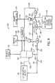
- FIG. 2 illustrates an embodiment of the GPU 108 having an H 2 S absorption section 150, a CO 2 absorption section 152, and a H 2 S recovery and solvent stripping section 154.
- the H 2 S absorption section 150 provides a first gaseous stream 156 to the CO 2 absorption section 152 and receives a first solvent stream 158 from the CO 2 absorption section 152.
- the gaseous stream 156 includes a stream of syngas that is lean in H 2 S and is rich in CO 2 at its respective pressure.
- the first gaseous stream 156 is the product of H 2 S removal from the raw or untreated syngas 109 produced within a gasifier (e.g., gasifier 106 of FIG. 1 ).
- the CO 2 absorption section 152 utilizes a solvent 160, such as a physical or chemical solvent (e.g., a methyl tert- butyl ether of polyethylene glycol (MTBPG), a methyl isopropyl ether of polyethylene glycol (MIPG), a methyl ethyl ether of polyethylene glycol (MEPG), or a dimethyl ether of polyethylene glycol (DEPG)), or a combination thereof, to remove a substantial portion of the CO 2 contained within the first gaseous stream 156 (e.g., at least approximately 50, 60, 70, 80, or 90% removal) to produce the first solvent stream 158 and the treated syngas 115.
- a solvent 160 such as a physical or chemical solvent (e.g., a methyl tert- butyl ether of polyethylene glycol (MTBPG), a methyl isopropyl ether of polyethylene glycol (MIPG), a methyl ethyl ether of polyethylene glycol (MEPG
- the first solvent stream 158 contains a significant amount of CO 2 , and in some embodiments may be saturated in CO 2 at its respective pressure. Generally, the first solvent stream 158 may be considered lean in H 2 S and rich in CO 2 . As discussed in further detail below with respect to FIG. 3 , the first solvent stream 158 may be used to remove H 2 S from the raw or untreated syngas 109 in the H 2 S absorption section 150. Using the first solvent stream 158, the H 2 S absorption section 150 therefore produces a second solvent stream 162, which is rich in both H 2 S and CO 2 .
- this solvent stream that is manipulated to address various desired specifications in the recovered CO 2 114 and recovered H 2 S 164 (e.g., an acid gas stream) for sulfur processing using both the CO 2 absorption section 152 and the H 2 S recovery and solvent stripping section 154.
- recovered CO 2 114 and recovered H 2 S 164 e.g., an acid gas stream
- the recovered CO 2 114 may include a CO 2 stream for carbon capture 166 and a CO 2 stream for recycle to the gasifier 168 (e.g., gasifier 106 of FIG. 1 ).
- the specifications of each of these may be substantially the same, or they may be different, depending on process requirements. For example, it may be desirable for the CO 2 stream for carbon capture 166 to be greater than approximately 90% CO 2 by volume, or even greater than approximately 95% CO 2 by volume.
- the specifications for the recovered H 2 S for sulfur processing 164 may call for a minimal level of H 2 S, such that the recovered H 2 S stream 164 is at least approximately 20%, 25%, or at least approximately 30% H 2 S by volume.
- the H 2 S recovery and solvent stripping section 154 uses a stripping gas 170, such as a relatively non-reactive gas (e.g., N 2 , Ar, He), to separate the CO 2 and H 2 S from the solvent in the second solvent stream 162.
- a stripping gas 170 such as a relatively non-reactive gas (e.g., N 2 , Ar, He)
- the H 2 S recovery and solvent stripping section 154 internally produces a gaseous mixture having the stripping gas, CO 2 , and H 2 S.
- This gaseous mixture is counterflowed with a third solvent stream 172 from the CO 2 absorption section 152.
- the third solvent stream 172 is rich in CO 2 and lean in H 2 S at its respective pressure.
- the stream 172 When the stream 172 is counterflowed with the gaseous mixture, the stream 172 is capable of removing H 2 S from the gaseous mixture. Further, as discussed in detail below with respect to FIG. 5 , in accordance with an embodiment, the third solvent stream 172 and the gaseous mixture are pressure matched within a mixing vessel such that the H 2 S of the gaseous mixture displaces the CO 2 of the third solvent stream 172 into the vapor phase. Accordingly, a second gaseous stream 174 that is rich in CO 2 and substantially free of H 2 S is produced, and contributes to the overall recovered CO 2 114. That is, the overall amount of recovered CO 2 may increase.
- a solvent mixture that is rich in the H 2 S removed from the gaseous mixture is also internally produced within the H 2 S recovery and solvent stripping section 154.
- This solvent mixture is further processed (e.g., flashed) to produce a recycle solvent 176 and the H 2 S stream 164.
- this recovery method enhances the overall amount and concentration of recovered H 2 S.
- an H 2 S absorber (e.g., H 2 S absorber 190) is intended to denote any vessel in which H 2 S is absorbed or otherwise taken into a solvent, such as a physical or chemical solvent, from a gaseous mixture or another solvent stream having H 2 S.
- the H 2 S absorber may absorb only some of the H 2 S, or all of the H 2 S from a gaseous mixture.
- a CO 2 absorber is intended to denote any vessel in which CO 2 is absorbed or otherwise taken into a solvent, such as a physical or chemical solvent, from a gaseous mixture or another solvent stream having CO 2 .
- the CO 2 absorber may absorb only some of the CO 2 , or all of the CO 2 from a gaseous mixture.
- the first solvent stream 158 is used to remove, within the H 2 S absorber 190, a substantial portion of the H 2 S from untreated syngas 109 flowing along a path between the gasifier 106 and the GPU 108. Specifically, as the untreated syngas 109 progresses through this path, it enters the H 2 S absorber 190, where it is mixed with the first solvent stream 158.
- the H 2 S absorber 190 may be a vessel, such as a column or elongated tank, which is configured to allow mixing of the untreated syngas 109 with the first solvent stream 158.
- the untreated syngas 109 enters the H 2 S absorber 190 at a lower area of the H 2 S absorber 190.
- the first solvent stream 158 enters into the H 2 S absorber 190 at an upper area.
- the untreated syngas 109 is allowed to efficiently mix with the first solvent stream 158 via a countercurrent effect.
- the first solvent stream 158 mixes with the untreated syngas 109, it removes a substantial portion of the H 2 S from the untreated syngas 109 along with some CO 2 .
- a stream of sweetened syngas exits the H 2 S absorber 190 as the first gaseous stream 156, while the second solvent stream 162 that is rich in H 2 S is provided to the H 2 S recovery and solvent stripping section 154.
- the solubility of H 2 S within certain solvents may be greater than the solubility of other gaseous components (e.g., syngas, CO 2 ) at reduced temperatures and increased pressures (e.g., above standard temperature and pressure).
- a heat exchanger 196 e.g., a chiller
- a pump 198 may be disposed along a solvent path 200 to cool and flow, respectively, the first solvent stream 158 to enable enhanced uptake of the H 2 S into the solvent.
- the stream 158 may be pressurized to between approximately 27 and 42 bar and cooled to between approximately 0 and 20 °C.
- the solvent stream 158 flowing into the H 2 S absorber 190 may be at a pressure between approximately 30 and 40 bar, 32 and 38 bar, or 34 and 36 bar.
- the ability of the solvent of the stream 158 to dissolve sulfur gases i.e., H 2 S
- the first gaseous stream 156 flowing through a gas path 204 to the CO 2 absorber 192 may have at most between approximately 5 and 55 ppmv H 2 S (e.g., approximately 5, 10, 15, 20, 25, 30, 35, 40, 45, 50, or 55 ppmv).
- solvent 160 such as recycle solvent
- solvent 160 may be directed via path 202 to the CO 2 absorber 192.
- the first gaseous stream 156 flowing though the gas path 204 enters a bottom portion of the CO 2 absorber 192.
- Mixing produced by a countercurrent between the downward-flowing stream of the solvent 160 and the upward-rising first gaseous stream 156 causes a stream of CO 2 -saturated solvent 206 to exit the CO 2 absorber 192 via path 208, which is bifurcated.
- the path 208 bifurcates into the solvent path 200 and an additional solvent path 210 leading a section for CO 2 recovery 212.
- the pump 198 may at least partially motivate the first solvent stream 158 through the path 200, and the level at which it provides motive force may at least partially affect the amount of the CO 2 -saturated solvent 206 sent to the path 200 versus the path 210.
- the level of CO 2 recovered and the concentration of H 2 S recovered in acid gas may be affected by the ratio in which the CO 2 -saturated solvent 206 is provided to the path 200 versus the path 210.
- the ratio in which the CO 2 -saturated solvent 206 is provided to the path 200 versus the path 210 may be affected by the ratio in which the CO 2 -saturated solvent 206 is provided to the path 200 versus the path 210.
- increasing the fraction of the CO 2 -saturated solvent 206 sent along path 210 results in greater CO 2 recovery and H 2 S concentration by the GPU 108.
- the untreated syngas 109 is low in H 2 S (i.e., the fuel source 102 is low in sulfur)
- dividing the CO 2 -saturated solvent 206 such that greater than approximately 90% of the CO 2 -saturated solvent 206 in path 208 is sent to path 210 results in enhanced H 2 S concentrations in the acid gas recovered at the H 2 S recovery and solvent stripping section 154. That is, in certain situations, the fuel source 102 may relatively low in sulfur. In these situations, a target amount for syngas may be attained, but the amount of sulfur recovered may not meet appropriate levels for sulfur recovery.
- a large portion (e.g., approximately 90%) of the CO 2 -saturated solvent 206 is provided to path 210, which boosts the concentration of sulfur in a stream of recovered acid gas.
- reducing the temperature of the CO 2 -saturated solvent 206 at the heat exchanger 196 to between approximately 0 and 20°C (e.g., 15, 10, 5, or 0 °C) may facilitate such enhanced concentration.
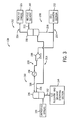
- FIG. 4 A schematic diagram illustrating an embodiment of the CO 2 absorption section 152 is illustrated in FIG. 4 .
- the CO 2 absorption section 152 of FIG. 4 includes the CO 2 absorber 192 and various flash vessels configured for CO 2 recovery.
- the CO 2 absorber 192 is configured to scrub the first gaseous stream 156, which is lean in H 2 S and rich in CO 2 , to remove a substantial portion of the CO 2 to produce the treated syngas 115 and the stream of CO 2 -saturated solvent 206. Again, a portion of the stream 206 is sent along path 200 to the H 2 S absorber 180 ( FIG. 3 ), while another portion of the stream 206 is sent along the solvent path 210 for CO 2 recovery as a first solvent mixture 218.
- the solvent path 210 leads to a series of flash vessels including a high pressure (HP) flash vessel 220, a medium pressure (MP) flash vessel 222, and a low pressure (LP) flash vessel 224.
- HP high pressure
- MP medium pressure
- LP low pressure
- flash is intended to denote a flash evaporation.
- the vessel when a vessel "flashes" a solvent mixture, the vessel performs a flash evaporation of the solvent mixture, with at least a portion of the solvent undergoing a rapid volatilization.
- the flash vessels are configured to sequentially reduce the pressure of the first solvent mixture 218, which produces CO 2 in the vapor phase for CO 2 capture and/or recycle.
- the solvent path 210 first leads to the HP flash vessel 220, which flashes the first solvent mixture 218 to produce a first stream of CO 2 226 at a respective first pressure.
- the HP flash vessel 220 may be operated at a pressure between approximately 6 and 27 bar, such as approximately 8, 10, 12, 14, 16, 18, 20, 22, 24, or 26 bar, with the first stream of CO 2 226 having substantially the same pressure.
- the first stream of CO 2 226 is sent to a recycle compressor 228, which produces the stream of CO 2 168.
- the recycle CO 2 168 may be used as a recycle stream to the gasifier (e.g., gasifier 106 of FIG. 1 ), to the H 2 S absorber 190, to areas of the system 100 of FIG. 1 between the gasifier 106 and the H 2 S absorber 190, or any suitable section in the system 100.
- the gasifier e.g., gasifier 106 of FIG. 1
- the H 2 S absorber 190 to areas of the system 100 of FIG. 1 between the gasifier 106 and the H 2 S absorber 190, or any suitable section in the system 100.
- the HP flash vessel 220 also produces a second solvent mixture 230, which includes a solvent saturated in CO 2 and lean in H 2 S (e.g., substantially free of H 2 S) at a respective pressure substantially equal to the HP flash vessel 220.
- the second solvent mixture 230 flows along the solvent path 210 to the MP flash vessel 222.
- the MP flash vessel 222 is configured to flash the second solvent mixture 230 at its operating pressure, which is lower than the pressure of the HP flash vessel 220.
- the operating pressure of the MP flash vessel 222 may be between approximately 4 and 21 bar, such as between approximately 6 and 20 bar, 8 and 18 bar, 10 and 16 bar, or between approximately 12 and 14 bar.
- the MP flash vessel 222 produces a second CO 2 stream 232, which is split into a first CO 2 path 234 leading to the recycle compressor 228 and a second CO 2 path 236 leading to a carbon capture compressor 238, which is configured to produce the CO 2 stream 166 ( FIG. 2 ).
- the CO 2 stream 166 is sent to various plant facilities for carbon capture, such as a carbon capture island 239.
- the MP flash vessel 222 also produces a third solvent mixture 240, which is rich in CO 2 and lean in H 2 S at its respective pressure (e.g., substantially the same as the MP flash vessel 222).
- the third solvent mixture 240 is split, with a first portion being provided along the main solvent path 210 to the LP flash vessel 224, and a second portion being split into a divergent solvent path 242.
- the second portion of the third solvent mixture 240 is the third solvent stream 172, which is utilized in the H 2 S recovery and solvent stripping section 154.
- the third solvent stream 172 which is rich in CO 2 and lean in H 2 S, is utilized to remove H 2 S from a gaseous mixture of CO 2 and H 2 S produced within the H 2 S recovery and solvent stripping section 154.
- the second gaseous stream 174 that is rich in CO 2 and substantially free of H 2 S is produced and is provided to the carbon capture compressor 238.
- the first portion is provided to the LP flash vessel 224, which is operated at a respective pressure that is lower than the pressure of the MP flash vessel 222.
- the pressure of the LP flash vessel 224 may be between approximately 1 and 6 bar, such as between approximately 1 and 5, or 2 and 4 bar. Again, any pressure that is lower than the pressures of the MP and HP flash vessels 220, 224 is presently contemplated.
- the LP flash vessel 224 flashes the third solvent mixture 240 to produce a third CO 2 stream 244, which is provided to the carbon capture compressor 238.
- the LP flash vessel 224 also produces a fourth solvent mixture 246, which is saturated in CO 2 and lean in H 2 S at a pressure that is substantially equal to that of the LP flash vessel 224.
- the fourth solvent mixture 246 is provided as a source of recycle solvent to the CO2 absorber 192.
- the fourth solvent mixture 246 may be sent, in addition to or in lieu of the CO2 absorber 192, to other areas of the system, such as to an ultra-low pressure flash vessel (LLP) flash vessel, a storage tank (e.g., a solvent storage tank), heat exchangers, or similar areas of the plant.
- LLP ultra-low pressure flash vessel
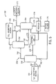
- the H 2 S recovery and solvent stripping section 154 is configured to use a CO 2 rich, H 2 S lean solvent stream to remove H 2 S from a H 2 S/CO 2 gas mixture. In performing this removal, the section 154 increases recovered H 2 S while enabling enhanced CO 2 recovery.
- One embodiment of the H 2 S recovery and solvent stripping section 154 is depicted schematically in FIG. 5 . As illustrated, the H 2 S recovery and solvent stripping section 154 includes an H 2 S concentrator 250, an H2S re-absorber 252, and a solvent stripper 254.
- the H 2 S concentrator 250 is configured to receive the second solvent stream 162, which is rich in both H 2 S and CO 2 , along a first solvent path 256, from the H 2 S absorption section 150.
- the H 2 S concentrator 250 receives the second solvent stream 162 from the H 2 S absorber 190.
- the H 2 S concentrator 250 also receives the stripping gas 170 from a gas path 258.
- the stripping gas 170 may include any substantially inert gas as noted above, and flows against the second solvent stream 162 within the H 2 S concentrator 250.
- an H 2 S concentrator as defined herein, is intended to denote any vessel in which H 2 S is concentrated into a solvent mixture or a gas mixture.
- the first gaseous mixture 260 flows along the gas path 258 to the H 2 S re-absorber 252.
- the H 2 S re-absorber 252 is also disposed along the divergent solvent path 242, which diverges from the main solvent path 210 at the MP flash vessel 222 as illustrated in FIG. 4 .
- an H 2 S re-absorber as defined herein, is intended to denote any vessel in which H 2 S is absorbed or otherwise taken into a solvent from a gaseous mixture having the H 2 S that was first removed from a solvent mixture in a separate vessel.
- the H 2 S re-absorber 252 re-absorbs H 2 S from the gaseous mixture 260 having the H 2 S that was first removed within the H 2 S concentrator 250.
- the first solvent path 256 is configured to flow a first solvent mixture 262, which may include some CO 2 and some H 2 S, from the H 2 S concentrator 250 to the solvent stripper 254.
- the first solvent path 256 couples the H 2 S concentrator 250 to the solvent stripper 254.
- various heat exchangers and/or pumps may also be disposed between the H 2 S concentrator 250 and the solvent stripper 254 to meet certain specifications for processing the first solvent mixture 262 at the solvent stripper 254. Such processing is discussed in further detail below.
- the first gaseous mixture 260 is mixed, within the H 2 S-re-absorber 252, with the third solvent stream 172 produced within the CO 2 absorption section 152.
- the third solvent stream 172 is produced at the MP flash vessel 222 such that the third solvent stream 172 includes a solvent that is saturated in CO 2 at medium pressure.
- the third solvent stream 172 may be produced using the HP flash vessel 220 and/or the LP flash vessel 224.
- the third solvent stream 172 may be saturated in CO 2 at high pressure, medium pressure, or low pressure. However, in accordance with the illustrated embodiment, the third solvent stream 172 is saturated in CO 2 at medium pressure. Such a pressure may be desirable to match (e.g., be substantially equal to) the pressure of the first gaseous mixture 260. Generally, however, the H 2 S re-absorber 252 and the flash vessel used to generate the third solvent stream 172 may be operated at respective pressures that are within approximately 20% of each other, within approximately 10% of each other, within approximately 5% of each other, or at approximately the same pressure. Such relative pressure levels may enable the H 2 S of the first gaseous mixture 260 to displace the CO 2 of the third solvent stream 172.
- the first gaseous mixture 260 is counterflowed with the third solvent stream 172 within the H 2 S re-absorber 252 such that H 2 S within the first gaseous mixture 260 is absorbed into the solvent of the third solvent stream 172.
- the H 2 S in the first gaseous mixture 260 may also displace some or substantially all of the CO 2 contained within the first solvent mixture 260 due to its enhanced solubility in the solvent relative to CO 2 to produce the second gaseous stream 174, which is rich in CO 2 and substantially free of H 2 S, as an overhead gas.
- the second gaseous stream 174 may also include the stripping gas.
- the H 2 S re-absorber 252 may include any one or a combination of features for enhancing liquid-vapor contact and mixing. Accordingly, the H 2 S re-absorber may include one or more valve trays, packed columns having spherical or shape-rounded elements for enhancing surface area, Raschig rings, or any combination thereof.
- the H 2 S re-absorber may include one or more valve trays, packed columns having spherical or shape-rounded elements for enhancing surface area, Raschig rings, or any combination thereof.
- this mixing between approximately 20 and 100% of the H 2 S may be removed from the first gaseous mixture 260. For example, between approximately 40 and 100%, 60 and 100%, 80 and 100%, 90 and 99%, or between approximately 92 and 98% of the H 2 S may be removed from the first gaseous mixture 260.
- At least approximately 10% of the CO 2 within the third solvent mixture 172 may be displaced into the vapor phase by the H 2 S of the first gaseous mixture 260.
- between approximately 10 and 100% of the CO 2 may be displaced into the vapor phase, such as between approximately 20 and 100%, 30 and 100%, 40 and 100%, 50 and 99%, or between approximately 60 and 90%.
- at least approximately 60%, at least approximately 75%, or at least approximately 85% of the CO 2 may be displaced.
- the H 2 S re-absorber 252 produces the second gaseous stream 174, which is rich in CO 2 and substantially free of H 2 S, and a second solvent mixture 270, which is rich in H 2 S and lean in CO 2 .
- the second solvent mixture 270 is substantially free of CO 2 .
- the second solvent mixture 270 flows along the divergent solvent path 242 to the solvent stripper 254. Accordingly, the solvent of the second solvent mixture 270 may combine with the first solvent mixture 262.
- the solvent stripper 254 may flash the second and third solvent mixtures 268, 270 (or the first and third solvent mixtures 262, 270) to generate the recovered H 2 S stream 164 as an overhead acid gas and the recycle solvent 176.
- the recycle solvent 176 may be produced by the solvent stripper 254 in combination with a reboiler 274.
- the reboiler 274 is configured to heat a stripped solvent mixture 276 output by the solvent stripper 254 to a boil, and may, in certain embodiments, also flow a stripping gas (e.g., a portion of stripping gas 170) against the boiling stripped solvent mixture 276.
- the stripping gas 170 therefore recycles some vaporized solvent, some CO 2 , and some H 2 S to the solvent stripper 254 as a reboiled gaseous mixture 278.
- the recovered H 2 S stream 164 may be provided to a sulfur processor (e.g., a Claus reactor) within a sulfur recovery section 272 for isolating elemental sulfur. Accordingly, the amount of sulfur recovered by the GPU 108 may depend at least partially on the H 2 S concentration of the third solvent stream 270. Again, the present embodiments provide for an enhancement in this concentration by using the third solvent stream 172 to isolate H 2 S from the first gaseous mixture 260.
- a sulfur processor e.g., a Claus reactor
- the present embodiments provide for an enhancement in this concentration by using the third solvent stream 172 to isolate H 2 S from the first gaseous mixture 260.
Landscapes
- Chemical & Material Sciences (AREA)
- Engineering & Computer Science (AREA)
- Analytical Chemistry (AREA)
- General Chemical & Material Sciences (AREA)
- Oil, Petroleum & Natural Gas (AREA)
- Chemical Kinetics & Catalysis (AREA)
- Health & Medical Sciences (AREA)
- Biomedical Technology (AREA)
- Environmental & Geological Engineering (AREA)
- Life Sciences & Earth Sciences (AREA)
- Sustainable Development (AREA)
- Gas Separation By Absorption (AREA)
- Industrial Gases (AREA)
- Treating Waste Gases (AREA)
Applications Claiming Priority (1)
| Application Number | Priority Date | Filing Date | Title |
|---|---|---|---|
| US13/429,212 US8945292B2 (en) | 2012-03-23 | 2012-03-23 | System for recovering acid gases from a gas stream |
Publications (1)
| Publication Number | Publication Date |
|---|---|
| EP2641646A1 true EP2641646A1 (en) | 2013-09-25 |
Family
ID=47901897
Family Applications (1)
| Application Number | Title | Priority Date | Filing Date |
|---|---|---|---|
| EP13160674.1A Withdrawn EP2641646A1 (en) | 2012-03-23 | 2013-03-22 | System for recovering acid gases from a gas stream |
Country Status (6)
| Country | Link |
|---|---|
| US (1) | US8945292B2 (enExample) |
| EP (1) | EP2641646A1 (enExample) |
| JP (2) | JP2013199647A (enExample) |
| KR (1) | KR102029801B1 (enExample) |
| CN (1) | CN103316567B (enExample) |
| AU (1) | AU2013201475B2 (enExample) |
Families Citing this family (11)
| Publication number | Priority date | Publication date | Assignee | Title |
|---|---|---|---|---|
| DE102010041536A1 (de) * | 2010-09-28 | 2012-03-29 | Siemens Aktiengesellschaft | Verfahren zur Abscheidung von Kohlendioxid, sowie Gasturbinenanlage mit Kohlendioxid Abscheidung |
| EP3113862B1 (en) * | 2014-03-05 | 2021-05-26 | Bechtel Hydrocarbon Technology Solutions, Inc. | Method for enhanced separation of hydrogen sulfide and ammonia in a hydrogen sulfide stripper |
| US9731243B2 (en) * | 2014-06-30 | 2017-08-15 | Uop Llc | Low pressure re-absorber and its integration with sulfur-rich solvent flash drum or sulfur-rich solvent stripper in an absorption unit |
| US10495379B2 (en) * | 2015-02-27 | 2019-12-03 | Exxonmobil Upstream Research Company | Reducing refrigeration and dehydration load for a feed stream entering a cryogenic distillation process |
| TWM559886U (zh) * | 2017-11-10 | 2018-05-11 | 兆聯實業股份有限公司 | 電子級氨水的製造系統 |
| KR20230011393A (ko) | 2018-03-16 | 2023-01-20 | 퓨얼셀 에너지, 인크 | 고온 연료전지를 이용해서 수소를 생성하기 위한 시스템 및 방법 |
| CN110760341A (zh) * | 2019-10-28 | 2020-02-07 | 山西晋城无烟煤矿业集团有限责任公司 | 一种气流床煤气化闪蒸不凝气净化系统及其方法 |
| GB2593939B (en) * | 2020-04-09 | 2022-04-27 | Velocys Tech Limited | Manufacture of a synthetic fuel |
| US11931685B2 (en) * | 2020-09-10 | 2024-03-19 | Enhanced Energy Group LLC | Carbon capture systems |
| US11945716B2 (en) * | 2021-12-15 | 2024-04-02 | Saudi Arabian Oil Company | Adsorption-based Claus tail gas treatment |
| EP4457431A4 (en) | 2021-12-29 | 2025-10-08 | Ge Vernova Tech Gmbh | SYSTEMS TO IMPROVE COMBINED CYCLE POWER PLANT STEAM INTEGRATION WITH POST-COMBUSTION CARBON CAPTURE |
Citations (2)
| Publication number | Priority date | Publication date | Assignee | Title |
|---|---|---|---|---|
| EP2380653A2 (en) * | 2010-04-23 | 2011-10-26 | General Electric Company | System For Gas Purification And Recovery With Multiple Solvents |
| US20120006200A1 (en) * | 2010-07-06 | 2012-01-12 | General Electric Company | System for acid gas removal |
Family Cites Families (21)
| Publication number | Priority date | Publication date | Assignee | Title |
|---|---|---|---|---|
| ATE214967T1 (de) | 1995-06-06 | 2002-04-15 | Bp Corp North America Inc | Katalytisches abgasbehandlungssystem zur bekämpfung von fluchtigen chemischen emissionen |
| IT1275587B1 (it) * | 1995-07-21 | 1997-08-06 | Kinetics Technology | Processo per il trattamento del gas di coda di un impianto claus ed il contemporaneo arricchimento del gas di alimentazione di detto |
| US6090356A (en) * | 1997-09-12 | 2000-07-18 | Texaco Inc. | Removal of acidic gases in a gasification power system with production of hydrogen |
| US20020021994A1 (en) * | 1999-10-08 | 2002-02-21 | Blue Jerry D. | Sulfur recovery gasification process for spent liquor at high temperature and high pressure |
| US7147691B2 (en) * | 2002-09-27 | 2006-12-12 | 1058238 Alberta Ltd. | Acid gas enrichment process |
| JP4942935B2 (ja) * | 2002-12-17 | 2012-05-30 | フルー・コーポレイシヨン | ゼロに近い排出で酸性気体および汚染物質を除去する構成および方法 |
| US20040118126A1 (en) * | 2002-12-19 | 2004-06-24 | Ong James O.Y. | Use of a chemical solvent to separate CO2 from a H2S-rich stream |
| DE10332427A1 (de) * | 2003-07-16 | 2005-02-03 | Uhde Gmbh | Verfahren zur Entfernung von Schwefelwasserstoff und weiteren Sauergaskomponenten aus unter Druck befindlichen, technischen Gasen |
| CA2531818C (en) * | 2003-09-09 | 2010-06-08 | Fluor Corporation | Improved solvent use and regeneration |
| PL2117682T3 (pl) * | 2007-02-22 | 2013-03-29 | Fluor Tech Corp | Konfiguracje do produkcji dwutlenku węgla i wodoru ze strumieni zgazowywania |
| US8580001B2 (en) | 2008-08-21 | 2013-11-12 | General Electric Company | Method and apparatus for assembling gasification reactor injection devices |
| US8435325B2 (en) * | 2008-10-23 | 2013-05-07 | Hitachi, Ltd. | Method and device for removing CO2 and H2S |
| US20100183491A1 (en) | 2009-01-22 | 2010-07-22 | General Electric Company | Systems and methods for treating a stream comprising an undesirable emission gas |
| US8741225B2 (en) | 2009-09-24 | 2014-06-03 | General Electric Company | Carbon capture cooling system and method |
| CN101708414B (zh) * | 2009-12-31 | 2012-06-27 | 攀钢集团研究院有限公司 | 循环吸收法废气脱硫系统、方法及用途 |
| US20110162380A1 (en) | 2010-01-04 | 2011-07-07 | General Electric Company | Method to increase net plant output of a derated igcc plant |
| US8419843B2 (en) * | 2010-05-18 | 2013-04-16 | General Electric Company | System for integrating acid gas removal and carbon capture |
| US8512446B2 (en) | 2010-07-22 | 2013-08-20 | General Electric Company | High pressure conveyance gas selection and method of producing the gas |
| US9259680B2 (en) * | 2011-09-06 | 2016-02-16 | Frank Bela | Claus hydrocarbon destruction via staged solvent regeneration |
| WO2013049114A1 (en) * | 2011-09-26 | 2013-04-04 | Eig, Inc. | Simultaneous high efficiency capture of co2 and h2s from pressurized gas |
| BR112014013190A2 (pt) * | 2011-12-01 | 2017-06-13 | Statoil Petroleum As | processo com absorvedor de reator tipo tanque agitado continuamente e unidade de extração tipo tanque flash |
-
2012
- 2012-03-23 US US13/429,212 patent/US8945292B2/en active Active
-
2013
- 2013-03-07 AU AU2013201475A patent/AU2013201475B2/en active Active
- 2013-03-19 JP JP2013055843A patent/JP2013199647A/ja not_active Withdrawn
- 2013-03-21 KR KR1020130030378A patent/KR102029801B1/ko active Active
- 2013-03-22 EP EP13160674.1A patent/EP2641646A1/en not_active Withdrawn
- 2013-03-25 CN CN201310096414.4A patent/CN103316567B/zh active Active
-
2017
- 2017-05-18 JP JP2017098594A patent/JP6387147B2/ja active Active
Patent Citations (2)
| Publication number | Priority date | Publication date | Assignee | Title |
|---|---|---|---|---|
| EP2380653A2 (en) * | 2010-04-23 | 2011-10-26 | General Electric Company | System For Gas Purification And Recovery With Multiple Solvents |
| US20120006200A1 (en) * | 2010-07-06 | 2012-01-12 | General Electric Company | System for acid gas removal |
Also Published As
| Publication number | Publication date |
|---|---|
| JP6387147B2 (ja) | 2018-09-05 |
| AU2013201475B2 (en) | 2017-09-28 |
| JP2013199647A (ja) | 2013-10-03 |
| CN103316567A (zh) | 2013-09-25 |
| KR20130108157A (ko) | 2013-10-02 |
| US20130247766A1 (en) | 2013-09-26 |
| CN103316567B (zh) | 2018-06-08 |
| KR102029801B1 (ko) | 2019-10-08 |
| AU2013201475A1 (en) | 2013-10-10 |
| JP2017201017A (ja) | 2017-11-09 |
| US8945292B2 (en) | 2015-02-03 |
Similar Documents
| Publication | Publication Date | Title |
|---|---|---|
| US8945292B2 (en) | System for recovering acid gases from a gas stream | |
| US8696797B2 (en) | Carbon dioxide removal from synthesis gas at elevated pressure | |
| JP5619151B2 (ja) | 流体流、特に合成ガスからの二酸化炭素の回収方法 | |
| JP5695377B2 (ja) | 炭素捕獲冷却系及び方法 | |
| US9278312B2 (en) | System for recovering high-purity CO2 from gasification gas containing CO, CO2, COS and H2S | |
| JP2007254270A (ja) | 水素及び二酸化炭素を含むガス混合物の処理方法 | |
| US8562719B2 (en) | System for acid gas removal | |
| US8268266B2 (en) | System for heat integration within a gas processing section | |
| US8475571B2 (en) | System for gas purification and recovery with multiple solvents | |
| CN103534198B (zh) | 用于从含硫气态流中除去硫的方法和系统 |
Legal Events
| Date | Code | Title | Description |
|---|---|---|---|
| PUAI | Public reference made under article 153(3) epc to a published international application that has entered the european phase |
Free format text: ORIGINAL CODE: 0009012 |
|
| AK | Designated contracting states |
Kind code of ref document: A1 Designated state(s): AL AT BE BG CH CY CZ DE DK EE ES FI FR GB GR HR HU IE IS IT LI LT LU LV MC MK MT NL NO PL PT RO RS SE SI SK SM TR |
|
| AX | Request for extension of the european patent |
Extension state: BA ME |
|
| 17P | Request for examination filed |
Effective date: 20140325 |
|
| RBV | Designated contracting states (corrected) |
Designated state(s): AL AT BE BG CH CY CZ DE DK EE ES FI FR GB GR HR HU IE IS IT LI LT LU LV MC MK MT NL NO PL PT RO RS SE SI SK SM TR |
|
| STAA | Information on the status of an ep patent application or granted ep patent |
Free format text: STATUS: THE APPLICATION IS DEEMED TO BE WITHDRAWN |
|
| 18D | Application deemed to be withdrawn |
Effective date: 20181002 |