EP2640927B1 - Bohrverfahren zum bohren eines unterirdischen bohrlochs - Google Patents
Bohrverfahren zum bohren eines unterirdischen bohrlochs Download PDFInfo
- Publication number
- EP2640927B1 EP2640927B1 EP11788211.8A EP11788211A EP2640927B1 EP 2640927 B1 EP2640927 B1 EP 2640927B1 EP 11788211 A EP11788211 A EP 11788211A EP 2640927 B1 EP2640927 B1 EP 2640927B1
- Authority
- EP
- European Patent Office
- Prior art keywords
- drillstring
- drilling fluid
- fluid
- drilling
- bhp
- Prior art date
- Legal status (The legal status is an assumption and is not a legal conclusion. Google has not performed a legal analysis and makes no representation as to the accuracy of the status listed.)
- Active
Links
Images


Classifications
-
- E—FIXED CONSTRUCTIONS
- E21—EARTH OR ROCK DRILLING; MINING
- E21B—EARTH OR ROCK DRILLING; OBTAINING OIL, GAS, WATER, SOLUBLE OR MELTABLE MATERIALS OR A SLURRY OF MINERALS FROM WELLS
- E21B44/00—Automatic control systems specially adapted for drilling operations, i.e. self-operating systems which function to carry out or modify a drilling operation without intervention of a human operator, e.g. computer-controlled drilling systems; Systems specially adapted for monitoring a plurality of drilling variables or conditions
- E21B44/02—Automatic control of the tool feed
- E21B44/04—Automatic control of the tool feed in response to the torque of the drive ; Measuring drilling torque
-
- E—FIXED CONSTRUCTIONS
- E21—EARTH OR ROCK DRILLING; MINING
- E21B—EARTH OR ROCK DRILLING; OBTAINING OIL, GAS, WATER, SOLUBLE OR MELTABLE MATERIALS OR A SLURRY OF MINERALS FROM WELLS
- E21B21/00—Methods or apparatus for flushing boreholes, e.g. by use of exhaust air from motor
- E21B21/01—Arrangements for handling drilling fluids or cuttings outside the borehole, e.g. mud boxes
- E21B21/019—Arrangements for maintaining circulation of drilling fluid while connecting or disconnecting tubular joints
-
- E—FIXED CONSTRUCTIONS
- E21—EARTH OR ROCK DRILLING; MINING
- E21B—EARTH OR ROCK DRILLING; OBTAINING OIL, GAS, WATER, SOLUBLE OR MELTABLE MATERIALS OR A SLURRY OF MINERALS FROM WELLS
- E21B21/00—Methods or apparatus for flushing boreholes, e.g. by use of exhaust air from motor
- E21B21/08—Controlling or monitoring pressure or flow of drilling fluid, e.g. automatic filling of boreholes, automatic control of bottom pressure
-
- E—FIXED CONSTRUCTIONS
- E21—EARTH OR ROCK DRILLING; MINING
- E21B—EARTH OR ROCK DRILLING; OBTAINING OIL, GAS, WATER, SOLUBLE OR MELTABLE MATERIALS OR A SLURRY OF MINERALS FROM WELLS
- E21B44/00—Automatic control systems specially adapted for drilling operations, i.e. self-operating systems which function to carry out or modify a drilling operation without intervention of a human operator, e.g. computer-controlled drilling systems; Systems specially adapted for monitoring a plurality of drilling variables or conditions
Definitions
- Subterranean drilling of a bore hole or wellbore typically involves rotating a drill bit from surface or on a downhole motor at the remote end of a tubular drill string. It involves pumping a fluid down the inside of the tubular drillstring, through the drill bit, and circulating this fluid continuously back to surface via the drilled space between the hole/tubular, referred to as the annulus.
- This pumping mechanism is provided by positive displacement pumps that are connected to a manifold which connects to the drillstring, and the rate of flow into the drillstring depends on the speed of these pumps.
- the drillstring is comprised of sections of tubular joints connected end to end, and their respective outside diameter depends on the geometry of the hole being drilled and their effect on fluid hydraulics in the annulus.
- the entire drillstring and bit are rotated using a rotary table, or using an above ground motor mounted on the top of the drill pipe known as a top drive.
- the bit can also be turned independently of the drillstring by a drilling fluid powered downhole motor, integrated into the drillstring just above the bit. Therefore speed of operation of the bit can vary with either the speed of the surface rotary mechanism or by the rate of pumping of drilling fluid through the downhole motor.
- the bit is the apparatus which provides the necessary crushing/cutting action to penetrate the rock layers as the wellbore is drilled deeper, and it is used in combination with the weight provided by the entire drillstring that exists above it to provide the necessary force to penetrate the rock layers.
- Bit types vary and have different designs in their profile in regards to items such as cutter design and profile and are predominantly selected based on the formation type being drilled.
- the bit penetrates its way through layers of underground formations until it reaches target prospects - rocks which contain hydrocarbons at a given temperature and pressure.
- These hydrocarbons are contained within the pore space of the rock (i.e. the void space) and can contain water, oil, and gas constituents - referred to as reservoirs. Due to overburden forces from layers of rock above, these reservoir fluids are contained and trapped within the pore space at a known or unknown pressure, referred to as pore pressure.
- a fluid of a given density fills and circulates the annulus of the drilled hole.
- the purpose of this drilling fluid/mud is to lubricate, carry drilled rock cuttings to surface, cool the drill bit, and power the downhole motor and other tools.
- Mud is a very broad term and in this context it is used to describe any fluid or fluid mixture that covers a broad spectrum from air, nitrogen, misted fluids in air or nitrogen, foamed fluids with air or nitrogen, aerated or nitrified fluids, to heavily weighted mixtures of oil and water with solids particles.
- this fluid and its resulting hydrostatic pressure the pressure that it exerts at the bottom of the hole from its given density - prevent the reservoir fluids at their existing pore pressure from entering the drilled annulus.
- the drilling fluid must also exert a pressure less than the fracture pressure of the formation, which is where fluid will be forced into the rock as a result of pressure in the wellbore exceeding the formation's horizontal stress forces.
- the bottom hole pressure (BHP) exerted by the hydrostatic pressure of the drilling fluid is the primary barrier for preventing influx from the formation.
- BHP can be expressed in terms of static BHP or dynamic/circulating BHP.
- Static BHP relates to the BHP value when the mud pumps are not in operation.
- Dynamic or circulating BHP refers to the BHP value when the pumps are in operation during drilling or circulating. It is the density property of the drilling fluid system that is primarily used for controlling the BHP so an influx event does not occur.
- Conventional methods use the density of the drilling fluid to control a point pressure in the wellbore, for example at the bottom of the hole (BHP), and are not used for pressure control along the entire length of the wellbore.
- BHP managed pressure drilling
- ECD equivalent circulating density
- ECD Equivalent circulating density
- BHP bottom hole pressure
- the ECD can result in a bottom hole pressure that varies from being slightly to significantly higher than the bottom hole pressure when the drilling fluid is not being pumped through the system.
- the ECD is related to the circulating or drilling BHP in the sense that the ECD is calculated from the BHP.
- the ECD is directly related to the friction losses that are occurring along the entire length of the wellbore.
- BHP bottom hole temperature
- BHT bottom hole temperature
- the drilling fluid is pumped through the inside of the drillstring via a hose connected to the top of the drillstring, the hose injecting drilling fluid into the main internal bore of the drillstring.
- the fluid circulates down the entire internal length of the drillstring, through the bit, and returns to surface via the annulus. It carries with it drilled formation solids and keeps the drilled hole clean, thus substantially preventing a stuck bit or stuck pipe scenario as more solids enter the annulus from drilling.
- Friction losses create pressure losses along the fluid's flow path in the annulus, so significant pressure is required to move the mud along its flow path.
- the friction losses occur between the fluid and the contact surfaces of the well bore and drill pipe.
- Some of the factors affecting friction losses are the geometry of the drillstring relative to the wellbore and the resultant annular clearance, fluid properties such as viscosity, fluid flow rate, and drillstring rotation RPM. It takes one or more positive displacement pumps to push the mud through the system at a suitable rate to ensure that the mud will effectively move solids, clean the hole, and power the bit while drilling. As the mud flows up the annulus, the greatest pressure is generated at the bottom of the hole from the summation of all the frictional losses occurring along the entire wellbore length.
- the ECD and BHP are affected by the density of the drilling fluid, which is a variable that is controlled by use of additives in the drilling fluid.
- additives are well known in the art.
- a virgin or base fluid for a drilling fluid system with no additives has a specific density - by increasing the solids content in this fluid its density is increased. By diluting or decreasing the solids content in a drilling fluid its density is decreased. Both of these conditions are altered through mixing processes which occur at surface in the drilling fluid mud tanks and storage system.
- the density of a fluid is directly proportional to the hydrostatic pressure it exerts - a higher density fluid creates a higher hydrostatic pressure and vice versa.
- Additional pressure effects can be imposed on the BHP with a closed loop system, such as the case with managed pressure drilling or underbalanced drilling.
- flow is diverted by a device that seals around the tubular drillstring at surface, referred to as a rotating head, which diverts the return fluid flow via a pipe conduit, referred to as a flow line.
- the seal isolates the wellbore below from the atmosphere and provides pressure integrity to the system.
- the flow then passes through a choking mechanism known as a choke or control valve. By opening or closing the choke or control valve, back pressure is imposed on the total system the flowing return stream and annular volume, which increases or decreases the BHP.
- US2006/157282 discloses a managed pressure drilling method which uses a foam drilling fluid, and in which foam flow properties, such as viscosity and shear strength of the foam are monitored and controlled while the foam is still in the well bore to maintain the cuttings carrying capacity of the foam up to the surface of the well-bore.
- foam flow properties such as viscosity and shear strength of the foam
- GB2354783 discloses a method of downhole hydraulic calibration in which a plurality of hydraulic calibration measurements are made at a respective drill string RPM and flow rate within a hydraulic calibration range. A hydraulic baseline function is then determined which predicts with a known degree of accuracy, each of the hydraulic calibration measurements.
- WO02/50398 discloses a closed loop circulating system for drilling wells in which an adjustable choke is provided in the annulus return line, and the adjustable choke is controlled to alter the back pressure of the annulus, and thereby control kicks and fluid losses.
- Steps c, d, e and f may be carried out prior to steps a and b (i.e. before drilling has commenced).
- the desired drilling fluid flow rate range may be determined by establishing the flow rate required to achieve effective removal of cuttings and any other solid debris from the wellbore.
- the drillstring may be provided with a fluid operated motor which is operable to cause rotation of the bit, and in this case the minimum fluid flow rate to operate the motor and / or the maximum flow flow rate tolerated by the motor may be considered when determining the desired drilling fluid flow rate range.
- Viscosity is defined as the resistance of a fluid to flow, the resistance resulting from shear forces/stresses existing between the fluid and the surfaces in contact with the flow (drillpipe and the wellbore/casing walls). Viscosity varies with temperature and pressure - increasing temperatures generally decreases viscosity and vice versa, whilst increasing pressure increases viscosity and vice versa.
- drilling fluids behave with non-Newtonian fluid flow property - a fluid whose flow properties are not described by a single constant value of viscosity. This is because with Non-Newtonian fluids viscosity is not only influenced by temperature and pressure, but is also strongly related to the velocity/flow rate at which the mud flows through the wellbore.
- the injected flow rate of drilling fluid is a variable of the rate of the shear stress in the annulus, described herein.
- the shear rate and stress are also related to variables such as, but not limited to, drillpipe rotational RPM and cuttings loading/buildup in the annulus.
- drilling fluid viscosity is a key factor in the amount of friction loss generated in the annulus along the entire wellbore length whenever there is fluid in motion. Any fluids (including liquid and gas) moving along a solid boundary, such as the external surface of the drillpipe or the wellbore internal walls, will impose a force on the fluid-surface boundary, referred to as shear stress/force. The magnitude of this shear stress is directly proportional to the fluid viscosity.
- the shear rate is the rate at which the shear stress is applied and is also governed by the fluid viscosity.
- the method may further comprise stopping rotation of the drillstring, pumping drilling fluid into a side port adjacent the uppermost portion of the drillstring, ceasing pumping of drilling fluid into the uppermost end of the drillstring, connecting a new section of drill pipe to the uppermost end of the drillstring, commencing pumping of drilling fluid into the uppermost end of the new section of drillpipe, ceasing pumping of drilling fluid into the side port, and recommencing rotation of the drillstring.
- Gel strength is the measure of the ability of a chemical additive to be dispersed within a drilling fluid to develop and retain a gel form.
- the gel strength of a drilling fluid determines its ability to hold solids in suspension. It is based on its resistance to shear force, and in this case the forces acting on the drilling fluid as it flows upwards in the annulus - such as pipe rotation, and roughness factors associated with the different materials that the fluid is in contact with (drillpipe, formation, casing etc.).
- the bottom hole pressure is largely affected, decreasing in value which can lead to a multitude of events such as a kick if the BHP decreases below pore pressures, and cuttings drop out.
- a kick if the BHP decreases below pore pressures, and cuttings drop out.
- large variances in the drilling fluid properties are created from high bottom hole temperatures when static conditions exist.
- a method referred to as continuous circulation, has been developed to achieve constant circulation through a side bore in the pipe at surface before the top drive is disengaged for a connection. Circulation continues unimpeded via a special side bore that is integrated into the pipe, allowing for the drilling fluid to be circulated through this bore while the main hose is removed from the top of the drillstring and a new pipe is installed. The top drive is reengaged to the top of the new section of pipe, and, once the connection is complete, the circulation recommences down the main bore of the drillpipe. Circulation at the side bore then ceases and the side bore is closed with a plug.
- continuous circulation counteracts the negative effects on BHP associated with connections, and therefore it is a critical process for managing and controlling BHP.
- the method further comprises varying the rate of flow of drilling fluid into the uppermost end of the drillstring.
- the shear stress/force and shear rate are also directly proportional to the fluid velocity. Increasing the flow rate Q increases the fluid velocity which results in higher shear rates in the annulus and thus higher friction losses. Similarly, decreasing the flow rate Q decreases the fluid velocity and this results in lower shear rates in the annulus and thus lower friction losses. As a result, increasing the flow rate Q increases the BHP and ECD, and decreasing the flow rate Q decreases the BHP and ECD.
- the method further comprises varying the speed of rotation of the drillstring.
- the method comprises reducing the speed of rotation of the drillstring when preparing to connect a new section of drill pipe to the uppermost end of the drillstring, and simultaneously increasing the rate of flow of drilling fluid into the drillstring.
- the method may comprise increasing the speed of rotation of the drillstring after having connected a new section of drill pipe to the drillstring, and simultaneously decreasing the rate of flow of drilling fluid into the drillstring.
- the method comprises altering the BHP by operating an adjustable choke in a flow line through which drilling fluid leaves the borehole.
- step f of the method comprises adding chemical additives to the drilling fluid to alter its viscosity, which will be used as the primary component for controlling the BHP and the pressure/ECD profile along the entire well length.
- the additional of the chemical additives does not substantially alter the density of the drilling fluid.
- FIG. 1 shows a schematic illustration of a land-based system for drilling a subterranean borehole. It should be appreciated, however, that the invention may equally be used in relation to an off-shore drilling system.
- This figure shows a borehole 10 which extends into a geological formation 11 comprising a reservoir of fluid such as oil, gas or water.
- a drill string 12 extends down into the bore hole 10.
- BHA bottom hole assembly
- the uppermost end of the drill string 12 extends to a drilling rig (not shown for clarity).
- the borehole 10 is capped with a well head 18, and a closure device 20 such as a rotating blow out preventer (BOP) or rotating control device (RCD).
- BOP rotating blow out preventer
- RCD rotating control device
- the invention may equally be used with an open system that does not contain a capped wellbore or closure device, however, as will be discussed further below.
- the drill string 12 extends through the well head 18 and closure device 20, the closure device 20 having seals closure around the exterior of the drill string 12 to provide a substantially fluid tight seal around the drill string 12 whilst allowing the drill string to rotate about its longitudinal axis, and to be moved further down into and out of the borehole 10.
- the well head 18 and closure device 20 contain the fluid in the annulus 16.
- the drill string 12 extends from the closure device 20 to a driving apparatus 22 such as a top drive, and the uppermost end of the drill string 12 is connected to the outlet port of a standpipe manifold 24 which has an inlet port connected by an inlet line to a pump 26.
- the wellhead 18 includes a side port 18a which is connected to an annulus return line 28, and which provides an outlet for fluid from the annulus 16.
- the annulus return line extends to a reservoir 34 of drilling fluid via an adjustable choke or valve 30 and a flow meter (such as a Coriolis flow meter) which is downstream of the choke / valve 30.
- Filters and / or shakers are generally provided to remove particulate matter such as drill cuttings from the drilling fluid prior to its return to the reservoir 34.
- the driving apparatus 22 rotates the drill string 12 about its longitudinal axis so that the drill bit cuts into the formation, and the pump 26 is operated to pump drilling fluid from the reservoir 34 to the standpipe manifold 24 and into the drill string 12 where it flows into the annulus 16 via the BHA 14.
- the mud and drill cuttings flow up the annulus 16 to the well head 18, and into the annulus return line 28, and the adjustable choke or valve 30 may be operated to restrict flow of the drilling fluid along the annulus return line 28, and, therefore, to apply a back-pressure is applied to the annulus 16.
- This back-pressure may be increased until the fluid pressure at the bottom of the wellbore 10 (the bottom hole pressure) is deemed sufficient to contain the formation fluids in the formation 11 whilst minimising the risk of fracturing the formation or causing drilling fluid to penetrate the formation.
- the rate of flow of fluid out of the annulus 16 is monitored using the flow meter 32, and compared with the rate of fluid into the drill string 12, and this data may be used to detect a kick or loss of drilling fluid to the formation.
- Such a system is, for example, disclosed in US 6,575, 244 , and US 7,044,237 .
- each curve is a fluid with a given viscosity.
- the first fluid (1) has the lowest viscosity and fluid 3 has the highest viscosity.
- the initial plot points for each curve on the vertical axis are the yield points, representing the minimum forces required for each of the fluids to commence flowing. Therefore, when operation of the pump 26 is stopped and then recommenced, this is the force that must be overcome to initiate flow of drilling fluid down the drillstring and up the annulus. As the value of viscosity increases, the yield point of the fluid will increase.
- the horizontal axis is the rate of shear which is directly proportional to the rate at which drilling fluid is pumped by the pump 26 into the drilling string and back up the annulus (hereinafter referred to as the pump rate Q) - as the velocity of the fluid increases from increased pump rate Q, the shear stress and shear rate rises.
- the shear stress is related to the increasing magnitude of frictional losses generated in the annulus while fluids 1, 2, or 3 flow up the annulus at different flow rates. As this flow rate increases, shear rate and shear stress increases indicated by the curve.
- the method according to the invention uses this relationship between viscosity and frictional losses in selecting the optimal viscosity for the drilling fluid system to control the ECD, and ultimately the BHP.
- Fluid 1 with the lowest viscosity would expect to have the lowest BHP due to its lower shear stress which would result in lower friction losses in the annulus.
- Fluid 3 with the highest viscosity would expect to have the highest BHP due to its high shear stress which would result in higher friction losses in the annulus.
- the method according to the invention therefore includes the following steps:
- the upper and lower BHP limits are determined by the pore pressure and fracture pressure of the formation 11, and may be calculated using methods which are well known to persons of skill in the art, on the basis of information about the nature and structure of the formation 11 derived from geological surveys.
- the method according to the invention is advantageously carried out prior to drilling, it may additionally / alternatively be carried out during drilling, since the upper and lower BHP limits will commonly vary as drilling progresses.
- the effective viscosity is the actual viscosity of the fluid at the given shear rate which exists in the circulating system at a specific density and pump rate.
- the invention will use this data for modelling that will be performed during drilling when a fluid viscosity change is required.
- the invention will use a hydraulics model for accurately predicting the change in the friction losses along the wellbore length and the resultant effect on BHP before viscosity is changed in real time during drilling operations.
- the viscosity of the drilling fluid may be changed by adding chemical additives to the drilling fluid in the reservoir 34 as drilling progresses.
- the additives used to alter the viscosity of the drilling fluid do not affect its density. If the additives used for control of the viscosity of the drilling fluid also increase the weight/density of the drilling fluid, then this introduces an additional variable which will also directly affect BHP. In order to solely control the BHP with viscosity, it is necessary to use additives that will have negligible effects on the density/weight of the system.
- the viscosity affects the entire pressure profile along the well length from the frictional losses viscosity creates at each point along the well - density is more for a "point" control of pressure using principles of hydrostatic pressure (static/no flow conditions where the weight/density of the fluid prevents formation influx) and equivalent circulating density (when the pumps are operating and fluid is flowing the weight/density of the fluid plus friction losses in the annulus have a compound effect to prevent formation influx).
- the additives may comprise viscosifiers that are available in liquid or solid form. Generally, if you mix/disperse a solid into a fluid you increase the solids/particle concentration of the mixture, and this will increase its density. Conventionally, drilling fluids (muds) are weighted up/increased in density by adding barite which is a heavier solids particle that is dispersed into the mud system. A viscosifier additive that exists as a liquid in a 5 gallon pail/bucket should have a much less effect on the density of the overall drilling fluid system, as they are much more easily dispersed and contain less solids particles in their chemical composition.
- Solid viscosifiers require much smaller concentrations than other solid viscosifiers to achieve the same viscosity value in a drilling fluid system.
- solid viscosifiers are Xantham Gum, Bentonite, or Hydroxyethylcellulose (referred to as HEC).
- HEC Hydroxyethylcellulose
- an average concentration for Bentonite is 20-25 Ibs/bbl
- Xantham can be added at 1 Ib/bbl to achieve similar viscosity values. It would be expected that the density of the system that uses Bentonite would be affected on a much larger scale than the system which uses Xantham due to the high concentration required, and therefore it would be preferred to use Xantham with the inventive method to achieve the desired viscosity.
- a second reservoir of drilling fluid may be provided, and when it is determined that a change in the viscosity of the drilling fluid is required, the composition of the drilling fluid in the second reservoir may be adjusted to bring it to the new viscosity.
- the pump 26 may then be operated to draw drilling fluid from the second reservoir instead of the original reservoir 34, or an alternative pump may be operated instead of the original pump 26 to pump drilling fluid from the second reservoir into the drillstring 12. This process may be repeated with additional drilling fluid reservoirs when further viscosity changes are required.
- the effective viscosity is the actual viscosity of the fluid at the given shear rate which exists in the circulating system at a specific density and pump rate.
- the effective viscosity of the drilling fluid may be monitored during drilling using a conventional viscosity meter (such as fan meter) which may be positioned in the bottom hole assembly or at any other point in the drillstring 12 or annulus 16.
- the viscosity meter may be connected to a central control unit which displays the current effective viscosity reading to allow an operator to compare this with the desired viscosity, or, more preferably, is programmed to compare the effective viscosity with the desired viscosity, and issue a warning to an operator when the difference between the two exceeds a predetermined threshold. An operator may then make further changes to the composition of the drilling fluid to bring it to, or least closer to, the desired viscosity.
- the measured effective viscosity may be used in a hydraulics model to accurately predict the change in the friction losses along the wellbore length and the resultant effect on BHP before viscosity is changed in real time during drilling operations.
- FIG 3 this illustrates, by way of example, the evaluation of four different viscosities for a single fluid at a fixed density for drilling.
- the upper (5) and lower (4) pressure limits for drilling are shown, resulting in the BHP operating envelope (6).
- a minimum flow rate of drilling fluid will be required for effective removal of cuttings and other solid debris from the well bore.
- a minimum flow rate of drilling fluid is required to operate the downhole motor.
- the upper flow rate may be determined by various factors such as the maximum safe operating speed of the pump 26, the maximum permitted speed of operation of the downhole motor.
- Fluid 3 with viscosity C falls within the operating pressure margin for the required flow rate range, and is deemed the optimal viscosity to use in this section as it meets the desired target BHP.
- Fluid 1 with viscosity A falls below the lower limit for the target BHP, and fluid 4 with viscosity D exceeds the upper limit for BHP.
- Fluid 2 with viscosity B has flow rates which will meet the BHP criteria, but cannot provide the range of flow rates desired for the section.
- Figure 3 shows the same relationship between viscosity and Q that is exhibited in Figure 2 - as the flow rate is increased from X, velocity of the fluid increases in the annulus. This creates more friction from the shear stresses present, and as the velocity of flow rises from increased pump rate Q, the shear rate or the rate of which the shear stress is applied increases. The amount of shear forces present increases with the viscosity value of the fluid. This relationship is proportional, and thus friction loss in the annulus continues to increase with increases in pump rate and viscosity.
- FIG 4 this illustrates the drilling fluid behaviour during a period of non-circulation - for example during a connection period without a continuous circulation method in place.
- the target drilling BHP is represented by the horizontal dotted line (7).
- the circulating BHP starts to rise (8) before the pump rate is ceased due to cuttings that are in the annulus from drilling.
- the pumps are stopped.
- fluid velocity and fluid rate in the annulus reaches zero as circulation stops (9).
- the drilling fluid begins to gel. This gel strength is related to the viscosity of the fluid - in general the more viscous the fluid the higher the gel strength the fluid will have.
- FIG. 5 this illustrates the relationship between viscosity and BHP control expressed as a function of the ECD along the wellbore length.
- the graph represents a fluid at a fixed density and flow rate at 4 different viscosities as a function of ECD and well length/depth.
- the ECD magnitude increases with depth as friction losses increase with depth.
- each curve shifts to the right indicating increased friction losses in the annulus from increased shear stresses.
- the ECD shows the pressure control achieved at any point along the length of the wellbore by varying the viscosity.
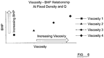
- FIG. 6 this illustrates the relationship between viscosity and pressure control expressed as a function of the BHP at the bottom of the well.
- the graph represents a fluid at a fixed density and flow rate at 4 different viscosities. As the viscosity increases, the points shift to the right and the BHP value increases. The increased shear stresses imposed in the annulus from increasing viscosity ultimately increases the total friction loss in the annulus and will increase the value of the BHP as a result.
- the shear stress/force and shear rate are also directly proportional to the fluid velocity. Increasing the flow rate increases the fluid velocity which results in higher shear rates in the annulus and thus higher friction losses. Similarly, decreasing the flow rate decreases the fluid velocity and this results in lower shear rates in the annulus and thus lower friction losses. As a result, increasing the flow rate increases the BHP and ECD, and decreasing the flow rate decreases the BHP and ECD.
- the flow rate is, of course, controlled by the Q, and therefore the speed of operation of the pump 26 can be used as further means of controlling the BHP.
- the BHP can be increased by increasing the speed of operation of the pump 26 or decreased by decreasing the speed of operation of the pump 26.
- control of the BHP can be achieved by operation of the adjustable choke valve 30 as in conventional managed pressure drilling systems, and as described above.
- This control can be used in addition to the other methods of BHP control described above.
Landscapes
- Engineering & Computer Science (AREA)
- Life Sciences & Earth Sciences (AREA)
- Geology (AREA)
- Mining & Mineral Resources (AREA)
- Physics & Mathematics (AREA)
- Environmental & Geological Engineering (AREA)
- Fluid Mechanics (AREA)
- General Life Sciences & Earth Sciences (AREA)
- Geochemistry & Mineralogy (AREA)
- Mechanical Engineering (AREA)
- Earth Drilling (AREA)
Claims (12)
- Verfahren zum Bohren eines unterirdischen Bohrlochs (10), umfassend:a) Pumpen einer Bohrflüssigkeit einen Bohrstrang (12) hinunter, wobei der Bohrstrang (12) ein Bohrwerkzeug (14) an einem Ende davon aufweist,b) Drehen des Bohrstrangs (12) um seine Längsachse, sodass das Bohrwerkzeug (14) ein Bohrloch (10) im Boden formt,c) Bestimmen eines erwünschten Durchflussmengenbereichs für die Bohrflüssigkeit,d) Bestimmen der erwünschten oberen und unteren Grenzen des Flüssigkeitsdrucks am Boden des Bohrlochs (dem BHP); dadurch gekennzeichnet, dass das Verfahren ferner folgende Schritte umfasst:e) Bestimmen der Viskosität der Bohrflüssigkeit, welche den BHP innerhalb des durch die oberen und unteren Grenzen festgelegten Bereichs über den ganzen oder den größten Teil des erwünschten Durchflussmengenbereichs der Bohrung beibehalten wird;f) Einstellen der Zusammensetzung einer Bohrflüssigkeit, um die Bohrflüssigkeit auf die bei Schritt e berechnete Viskosität zu bringen.
- Verfahren nach Anspruch 1, wobei die Schritte c, d, e und f vor den Schritten a und b ausgeführt werden.
- Verfahren nach einem vorhergehenden Anspruch, wobei der erwünschte Durchflussmengenbereich für die Bohrflüssigkeit durch Festsetzen der Durchflussmenge bestimmt wird, die erforderlich ist, um das effektive Entfernen von Bohrklein und irgendwelcher anderen festen Trümmer aus dem Bohrloch (10) zu erzielen.
- Verfahren nach einem vorhergehenden Anspruch, wobei der Bohrstrang (12) mit einem flüssigkeitsbetriebenen Motor versehen, der betreibbar ist, Drehung des Bohrwerkzeugs (14) zu bewirken, und die minimale Flüssigkeitsdurchflussmenge zum Betrieb des Motors und/oder die vom Motor tolerierte maximale Flüssigkeitsdurchflussmenge wird beim Bestimmen des Durchflussmengenbereichs für die Bohrflüssigkeit berücksichtigt.
- Verfahren nach einem vorhergehenden Anspruch, welches ferner das Stoppen der Drehung des Bohrstrangs (12), das Pumpen der Bohrflüssigkeit in eine Seitenöffnung angrenzend an den obersten Abschnitt des Bohrstrangs (12), das Beenden des Pumpens von Bohrflüssigkeit in das oberste Ende des Bohrstrangs (12), das Verbinden eines neuen Teils von Bohrgestänge mit dem obersten Ende des Bohrstrangs (12), das Beginnen mit dem Pumpen von Bohrflüssigkeit in das oberste Ende des neuen Teils von Bohrgestänge, das Beenden des Pumpens von Bohrflüssigkeit in die Seitenöffnung und den Wiederbeginn der Drehung des Bohrstrangs (12) umfasst.
- Verfahren nach einem vorhergehenden Anspruch, wobei das Verfahren ferner das Variieren der Durchflussmenge von Bohrflüssigkeit in das oberste Ende des Bohrstrangs (12) umfasst.
- Verfahren nach einem vorhergehenden Anspruch, wobei das Verfahren ferner das Variieren der Drehgeschwindigkeit des Bohrstrangs (12) umfasst.
- Verfahren nach einem vorhergehenden Anspruch, wobei das Verfahren ferner die Reduzierung der Drehgeschwindigkeit des Bohrstrangs (12) umfasst, wenn die Verbindung eines neuen Teils von Bohrgestänge mit dem obersten Ende des Bohrstrangs (12) vorbereitet und gleichzeitig die Durchflussmenge von Bohrflüssigkeit in den Bohrstrang (12) erhöht wird.
- Verfahren nach einem vorhergehenden Anspruch, wobei das Verfahren ferner die Erhöhung der Drehgeschwindigkeit des Bohrstrangs (12) umfasst, nach dem ein neues Teil von Bohrgestänge mit dem Bohrstrang (12) verbunden worden ist und gleichzeitig die Durchflussmenge von Bohrflüssigkeit in den Bohrstrang (12) verringert wird.
- Verfahren nach einem vorhergehenden Anspruch, wobei das Verfahren ferner die Änderung des BHP durch Betätigung einer einstellbaren Drossel (30) in einer Förderleitung (28) umfasst, durch welche die Bohrflüssigkeit das Bohrloch (10) verlässt.
- Verfahren nach einem vorhergehenden Anspruch, wobei der Schritt f des Verfahrens das Hinzufügen von chemischen Zusatzmitteln zur Bohrflüssigkeit umfasst, um ihre Viskosität zu ändern.
- Verfahren nach einem vorhergehenden Anspruch, wobei das Hinzufügen der chemischen Zusatzmittel im Wesentlichen die Dichte der Bohrflüssigkeit nicht ändert.
Applications Claiming Priority (3)
| Application Number | Priority Date | Filing Date | Title |
|---|---|---|---|
| US41424810P | 2010-11-16 | 2010-11-16 | |
| US13/223,676 US8684109B2 (en) | 2010-11-16 | 2011-09-01 | Drilling method for drilling a subterranean borehole |
| PCT/GB2011/052234 WO2012066327A2 (en) | 2010-11-16 | 2011-11-16 | Drilling method for drilling a subterranean borehole |
Publications (2)
| Publication Number | Publication Date |
|---|---|
| EP2640927A2 EP2640927A2 (de) | 2013-09-25 |
| EP2640927B1 true EP2640927B1 (de) | 2018-12-19 |
Family
ID=45044622
Family Applications (2)
| Application Number | Title | Priority Date | Filing Date |
|---|---|---|---|
| EP11788210.0A Active EP2640931B1 (de) | 2010-11-16 | 2011-11-16 | Verfahren und vorrichtung zum bohren eines bohrlochs |
| EP11788211.8A Active EP2640927B1 (de) | 2010-11-16 | 2011-11-16 | Bohrverfahren zum bohren eines unterirdischen bohrlochs |
Family Applications Before (1)
| Application Number | Title | Priority Date | Filing Date |
|---|---|---|---|
| EP11788210.0A Active EP2640931B1 (de) | 2010-11-16 | 2011-11-16 | Verfahren und vorrichtung zum bohren eines bohrlochs |
Country Status (11)
| Country | Link |
|---|---|
| US (2) | US8684109B2 (de) |
| EP (2) | EP2640931B1 (de) |
| CN (1) | CN103270242B (de) |
| AU (1) | AU2011330900A1 (de) |
| BR (1) | BR112013011990A2 (de) |
| CA (1) | CA2818072A1 (de) |
| MX (1) | MX2013005473A (de) |
| MY (1) | MY166114A (de) |
| SA (1) | SA111320918B1 (de) |
| SG (1) | SG190799A1 (de) |
| WO (2) | WO2012066325A2 (de) |
Families Citing this family (50)
| Publication number | Priority date | Publication date | Assignee | Title |
|---|---|---|---|---|
| US8684109B2 (en) | 2010-11-16 | 2014-04-01 | Managed Pressure Operations Pte Ltd | Drilling method for drilling a subterranean borehole |
| MX369745B (es) | 2013-03-20 | 2019-11-20 | Schlumberger Technology Bv | Control de sistemas de perforación. |
| US20140344301A1 (en) * | 2013-05-14 | 2014-11-20 | Chesapeake Operating, Inc. | System and method for managing drilling |
| CN105793513B (zh) * | 2013-12-23 | 2018-06-22 | 哈里伯顿能源服务公司 | 钻柱部分旋转速度的独立修改 |
| US10060842B2 (en) | 2013-12-24 | 2018-08-28 | Halliburton Energy Services, Inc. | Downhole viscosity sensor with smart fluid |
| US10883356B2 (en) | 2014-04-17 | 2021-01-05 | Schlumberger Technology Corporation | Automated sliding drilling |
| CA2966492C (en) | 2014-12-30 | 2019-09-17 | Neelesh V. DEOLALIKAR | Condition monitoring of electric motor |
| US9938784B2 (en) | 2015-07-13 | 2018-04-10 | Halliburton Energy Services, Inc. | Real-time frequency loop shaping for drilling mud viscosity and density measurements |
| US10577876B2 (en) | 2015-07-13 | 2020-03-03 | Halliburton Energy Services, Inc. | Estimating drilling fluid properties and the uncertainties thereof |
| US11268334B2 (en) | 2015-07-13 | 2022-03-08 | Halliburton Energy Services, Inc. | Real-time downhole drilling mud viscosity and density estimations |
| US20170122092A1 (en) | 2015-11-04 | 2017-05-04 | Schlumberger Technology Corporation | Characterizing responses in a drilling system |
| WO2017132297A2 (en) | 2016-01-26 | 2017-08-03 | Schlumberger Technology Corporation | Tubular measurement |
| US10695729B2 (en) | 2016-03-24 | 2020-06-30 | Highland Fluid Technology, Inc. | Optimizing drilling mud shearing |
| BR112018069569A2 (pt) | 2016-05-20 | 2019-01-29 | Halliburton Energy Services Inc | métodos e sistema de gerenciamento da densidade de circulação equivalente durante uma operação de furo de poço, e, meio legível por computador não transitório. |
| CN109328256A (zh) | 2016-05-25 | 2019-02-12 | 斯伦贝谢技术有限公司 | 基于图像的钻井作业系统 |
| RU2743526C2 (ru) * | 2016-09-26 | 2021-02-19 | Бристоль, Инк., Д/Б/А Ремоут Аутомейшен Солюшенз | Автоматизированная промывочная система для системы винтового насоса |
| US10036219B1 (en) | 2017-02-01 | 2018-07-31 | Chevron U.S.A. Inc. | Systems and methods for well control using pressure prediction |
| US11021944B2 (en) | 2017-06-13 | 2021-06-01 | Schlumberger Technology Corporation | Well construction communication and control |
| US11143010B2 (en) | 2017-06-13 | 2021-10-12 | Schlumberger Technology Corporation | Well construction communication and control |
| US11422999B2 (en) | 2017-07-17 | 2022-08-23 | Schlumberger Technology Corporation | System and method for using data with operation context |
| US20210062636A1 (en) | 2017-09-05 | 2021-03-04 | Schlumberger Technology Corporation | Controlling drill string rotation |
| US11378506B2 (en) | 2017-12-12 | 2022-07-05 | Baker Hughes, A Ge Company, Llc | Methods and systems for monitoring drilling fluid rheological characteristics |
| US10782197B2 (en) | 2017-12-19 | 2020-09-22 | Schlumberger Technology Corporation | Method for measuring surface torque oscillation performance index |
| US10760417B2 (en) | 2018-01-30 | 2020-09-01 | Schlumberger Technology Corporation | System and method for surface management of drill-string rotation for whirl reduction |
| DE112019001243T5 (de) | 2018-03-09 | 2020-11-26 | Schlumberger Technology B.V. | Integrierte Bohrlochkonstruktionssystem-Betriebsvorgänge |
| US11035219B2 (en) | 2018-05-10 | 2021-06-15 | Schlumberger Technology Corporation | System and method for drilling weight-on-bit based on distributed inputs |
| US10876834B2 (en) | 2018-05-11 | 2020-12-29 | Schlumberger Technology Corporation | Guidance system for land rig assembly |
| WO2019226149A1 (en) | 2018-05-21 | 2019-11-28 | Newpark Drilling Fluids Llc | System for simulating in situ downhole drilling conditions and testing of core samples |
| WO2019232516A1 (en) | 2018-06-01 | 2019-12-05 | Schlumberger Technology Corporation | Estimating downhole rpm oscillations |
| US12366152B2 (en) | 2018-06-04 | 2025-07-22 | Schlumberger Technology Corporation | Well construction workstation and control |
| US11788383B2 (en) * | 2018-10-02 | 2023-10-17 | Klx Energy Services Llc | Apparatus and method for removing debris from a wellbore |
| US10890060B2 (en) | 2018-12-07 | 2021-01-12 | Schlumberger Technology Corporation | Zone management system and equipment interlocks |
| US10907466B2 (en) | 2018-12-07 | 2021-02-02 | Schlumberger Technology Corporation | Zone management system and equipment interlocks |
| US11668162B2 (en) | 2018-12-31 | 2023-06-06 | Halliburton Energy Services, Inc. | Predicting downhole mechanical cleaning efficiency in wellbore walls during wellbore fluids displacements |
| CN109812710B (zh) * | 2019-01-28 | 2020-10-27 | 新昌县陆恒机械有限公司 | 一种油田输送管线增压装置 |
| US20230323742A1 (en) * | 2019-01-28 | 2023-10-12 | Russel Moore | Circumferential wear bands for oilfield tubulars |
| US11808133B2 (en) | 2019-05-28 | 2023-11-07 | Schlumberger Technology Corporation | Slide drilling |
| US20210063294A1 (en) * | 2019-09-03 | 2021-03-04 | Halliburton Energy Services, Inc. | In-line conical viscometer using shear stress sensors |
| US11514383B2 (en) | 2019-09-13 | 2022-11-29 | Schlumberger Technology Corporation | Method and system for integrated well construction |
| US11391142B2 (en) | 2019-10-11 | 2022-07-19 | Schlumberger Technology Corporation | Supervisory control system for a well construction rig |
| CA3160970A1 (en) * | 2019-12-31 | 2021-07-08 | Halliburton Energy Services,Inc. | Predict brake horsepower for a pump for viscous applications |
| US11916507B2 (en) | 2020-03-03 | 2024-02-27 | Schlumberger Technology Corporation | Motor angular position control |
| US12055027B2 (en) | 2020-03-06 | 2024-08-06 | Schlumberger Technology Corporation | Automating well construction operations based on detected abnormal events |
| US11933156B2 (en) | 2020-04-28 | 2024-03-19 | Schlumberger Technology Corporation | Controller augmenting existing control system |
| US11352871B2 (en) | 2020-05-11 | 2022-06-07 | Schlumberger Technology Corporation | Slide drilling overshot control |
| US11255189B2 (en) | 2020-05-20 | 2022-02-22 | Halliburton Energy Services, Inc. | Methods to characterize subterranean fluid composition and adjust operating conditions using MEMS technology |
| US11255191B2 (en) * | 2020-05-20 | 2022-02-22 | Halliburton Energy Services, Inc. | Methods to characterize wellbore fluid composition and provide optimal additive dosing using MEMS technology |
| US11060400B1 (en) | 2020-05-20 | 2021-07-13 | Halliburton Energy Services, Inc. | Methods to activate downhole tools |
| US11814943B2 (en) | 2020-12-04 | 2023-11-14 | Schlumberger Technoloyg Corporation | Slide drilling control based on top drive torque and rotational distance |
| US20230208321A1 (en) * | 2021-12-23 | 2023-06-29 | Richard Marion Mansell | Thrust Production via Quantized Inertia |
Family Cites Families (74)
| Publication number | Priority date | Publication date | Assignee | Title |
|---|---|---|---|---|
| US704423A (en) | 1902-02-26 | 1902-07-08 | Boyd W Allen | Wall-plate or shield for electric wires. |
| US1491986A (en) | 1922-02-01 | 1924-04-29 | Lorenzo H Greene | Coupling for drill pipes |
| US2158356A (en) | 1935-09-16 | 1939-05-16 | Continental Oil Co | Apparatus for oil well drilling |
| US2102555A (en) | 1936-07-02 | 1937-12-14 | Continental Oil Co | Method of drilling wells |
| US3338319A (en) | 1965-07-29 | 1967-08-29 | Bass Brothers Entpr Inc | Apparatus for maintaining balanced mud circulation to prevent blowouts |
| US3298385A (en) | 1965-09-22 | 1967-01-17 | Well Completions Inc | Constant circulating coupling device |
| US3470971A (en) | 1967-04-28 | 1969-10-07 | Warren Automatic Tool Co | Apparatus and method for automatically controlling fluid pressure in a well bore |
| GB2119046B (en) | 1982-04-21 | 1985-07-31 | Hoover Plc | Hose connector for a floor care appliance |
| US4448267A (en) | 1982-08-30 | 1984-05-15 | Crawford Iii Russell C | Door drilling Kelly |
| US4630675A (en) | 1985-05-28 | 1986-12-23 | Smith International Inc. | Drilling choke pressure limiting control system |
| US4685520A (en) | 1985-08-14 | 1987-08-11 | Mcdaniel Robert J | Open hole pipe recovery circulation valve |
| US4823877A (en) | 1985-08-14 | 1989-04-25 | Mcdaniel Robert J | Open hole pipe recovery circulation valve |
| US4770389A (en) | 1986-05-14 | 1988-09-13 | Chevron Research Company | Electric valve device |
| FR2619156B1 (fr) | 1987-08-07 | 1989-12-22 | Forex Neptune Sa | Procede de controle des venues de fluides dans les puits d'hydrocarbures |
| FR2619155B1 (fr) | 1987-08-07 | 1989-12-22 | Forex Neptune Sa | Procede d'analyse dynamique des venues de fluides dans les puits d'hydrocarbures |
| GB2239279B (en) | 1989-12-20 | 1993-06-16 | Forex Neptune Sa | Method of analysing and controlling a fluid influx during the drilling of a borehole |
| FR2659387A1 (fr) | 1990-03-12 | 1991-09-13 | Forex Neptune Sa | Methode d'estimation de la pression interstitielle d'une formation souterraine. |
| GB2290330B (en) | 1992-04-08 | 1996-06-05 | Baroid Technology Inc | Methods for controlling the execution of a well drilling plan |
| US5246203A (en) | 1992-06-29 | 1993-09-21 | M&M Supply Co. | Oilfield valve |
| US5431188A (en) | 1994-03-25 | 1995-07-11 | Master Flo Valve, Inc. | Flow trim for choke |
| US6206108B1 (en) * | 1995-01-12 | 2001-03-27 | Baker Hughes Incorporated | Drilling system with integrated bottom hole assembly |
| US6109368A (en) * | 1996-03-25 | 2000-08-29 | Dresser Industries, Inc. | Method and system for predicting performance of a drilling system for a given formation |
| EP1048819B1 (de) | 1996-05-03 | 2004-02-25 | Baker Hughes Incorporated | System zur Spülungsaufbereitung im geschlossenen Kreislauf zum Einsatz in Brunnenbohrungen |
| GB2314106B (en) | 1996-06-11 | 2000-06-14 | Red Baron | Multi-cycle circulating sub |
| WO1998016716A1 (en) | 1996-10-15 | 1998-04-23 | Maris Internatinal Limited | Continuous circulation drilling method |
| US5890549A (en) | 1996-12-23 | 1999-04-06 | Sprehe; Paul Robert | Well drilling system with closed circulation of gas drilling fluid and fire suppression apparatus |
| US6050348A (en) | 1997-06-17 | 2000-04-18 | Canrig Drilling Technology Ltd. | Drilling method and apparatus |
| AU8164898A (en) | 1997-06-27 | 1999-01-19 | Baker Hughes Incorporated | Drilling system with sensors for determining properties of drilling fluid downhole |
| US7174975B2 (en) | 1998-07-15 | 2007-02-13 | Baker Hughes Incorporated | Control systems and methods for active controlled bottomhole pressure systems |
| US6244631B1 (en) | 1999-03-02 | 2001-06-12 | Michael Payne | High efficiency drill pipe |
| US6427125B1 (en) | 1999-09-29 | 2002-07-30 | Schlumberger Technology Corporation | Hydraulic calibration of equivalent density |
| US7107875B2 (en) | 2000-03-14 | 2006-09-19 | Weatherford/Lamb, Inc. | Methods and apparatus for connecting tubulars while drilling |
| US6374925B1 (en) | 2000-09-22 | 2002-04-23 | Varco Shaffer, Inc. | Well drilling method and system |
| GB0026598D0 (en) | 2000-10-31 | 2000-12-13 | Coupler Developments Ltd | Improved drilling methods and apparatus |
| US20020112888A1 (en) | 2000-12-18 | 2002-08-22 | Christian Leuchtenberg | Drilling system and method |
| US6484816B1 (en) | 2001-01-26 | 2002-11-26 | Martin-Decker Totco, Inc. | Method and system for controlling well bore pressure |
| JP4689065B2 (ja) | 2001-03-26 | 2011-05-25 | カルソニックカンセイ株式会社 | 管体の仮固定構造 |
| US6575244B2 (en) | 2001-07-31 | 2003-06-10 | M-I L.L.C. | System for controlling the operating pressures within a subterranean borehole |
| US6904981B2 (en) | 2002-02-20 | 2005-06-14 | Shell Oil Company | Dynamic annular pressure control apparatus and method |
| US7185719B2 (en) | 2002-02-20 | 2007-03-06 | Shell Oil Company | Dynamic annular pressure control apparatus and method |
| US6755261B2 (en) | 2002-03-07 | 2004-06-29 | Varco I/P, Inc. | Method and system for controlling well fluid circulation rate |
| US8955619B2 (en) | 2002-05-28 | 2015-02-17 | Weatherford/Lamb, Inc. | Managed pressure drilling |
| US6814142B2 (en) | 2002-10-04 | 2004-11-09 | Halliburton Energy Services, Inc. | Well control using pressure while drilling measurements |
| US7055627B2 (en) | 2002-11-22 | 2006-06-06 | Baker Hughes Incorporated | Wellbore fluid circulation system and method |
| US7044239B2 (en) * | 2003-04-25 | 2006-05-16 | Noble Corporation | System and method for automatic drilling to maintain equivalent circulating density at a preferred value |
| GB0319317D0 (en) | 2003-08-16 | 2003-09-17 | Maris Tdm Ltd | Method and apparatus for drilling |
| EP1664478B1 (de) | 2003-08-19 | 2006-12-27 | Shell Internationale Researchmaatschappij B.V. | Bohrsystem und bohrverfahren |
| US7063161B2 (en) | 2003-08-26 | 2006-06-20 | Weatherford/Lamb, Inc. | Artificial lift with additional gas assist |
| US20050092523A1 (en) | 2003-10-30 | 2005-05-05 | Power Chokes, L.P. | Well pressure control system |
| GB2426274B (en) | 2004-02-20 | 2008-09-17 | Statoil Asa | Drill pipe header |
| US7163064B2 (en) | 2004-09-20 | 2007-01-16 | Devin International, Inc. | Surface flow valve and method |
| ITMI20051108A1 (it) | 2005-06-14 | 2006-12-15 | Eni Spa | Dispositivo e procedimento per l'inserimento di una nuova stringa di perforazione di un pozzo |
| WO2007005822A2 (en) | 2005-07-01 | 2007-01-11 | Board Of Regents, The University Of Texas System | System, program products, and methods for controlling drilling fluid parameters |
| WO2007016000A1 (en) | 2005-07-27 | 2007-02-08 | Baker Hughes Incorporated | Active bottomhole pressure control with liner drilling and compeltion system |
| US7836973B2 (en) * | 2005-10-20 | 2010-11-23 | Weatherford/Lamb, Inc. | Annulus pressure control drilling systems and methods |
| JP5164327B2 (ja) | 2005-12-26 | 2013-03-21 | カシオ計算機株式会社 | 撮影装置及びプログラム |
| CA2635097C (en) | 2006-01-05 | 2011-08-09 | At Balance Americas Llc | Method for determining formation fluid entry into or drilling fluid loss from a borehole using a dynamic annular pressure control system |
| WO2007124330A2 (en) | 2006-04-20 | 2007-11-01 | At Balance Americas Llc | Pressure safety system for use with a dynamic annular pressure control system |
| WO2008051978A1 (en) | 2006-10-23 | 2008-05-02 | M-I L.L.C. | Method and apparatus for controlling bottom hole pressure in a subterranean formation during rig pump operation |
| AU2007317276B2 (en) | 2006-11-07 | 2011-07-28 | Halliburton Energy Services, Inc. | Offshore universal riser system |
| ITMI20070228A1 (it) | 2007-02-08 | 2008-08-09 | Eni Spa | Apparecchiatura per intercettare e deviare un flusso di circolazione liquido |
| NO327556B1 (no) | 2007-06-21 | 2009-08-10 | Siem Wis As | Anordning og fremgangsmate for a opprettholde hovedsakelig konstant trykk pa og stromning av borevaeske i en borestreng |
| EP2415960B1 (de) | 2007-07-27 | 2017-04-12 | Weatherford Technology Holdings, LLC | Bohrsystem und -verfahren mit kontinuierlichem durchfluss |
| GB2451699B (en) | 2007-08-10 | 2009-06-24 | Brightwell Dispensers Ltd | Manifold apparatus |
| NO328945B1 (no) | 2007-08-15 | 2010-06-21 | I Tec As | Ventilseksjon og fremgangsmate for a opprettholde konstant borevaeskesirkulasjon under en boreprosess |
| US7857075B2 (en) * | 2007-11-29 | 2010-12-28 | Schlumberger Technology Corporation | Wellbore drilling system |
| US8201804B2 (en) | 2008-03-28 | 2012-06-19 | Semen J Strazhgorodskiy | Apparatus for uninterrupted flushing a well bore |
| GB0819340D0 (en) | 2008-10-22 | 2008-11-26 | Managed Pressure Operations Ll | Drill pipe |
| US7984770B2 (en) * | 2008-12-03 | 2011-07-26 | At-Balance Americas, Llc | Method for determining formation integrity and optimum drilling parameters during drilling |
| GB0905633D0 (en) | 2009-04-01 | 2009-05-13 | Managed Pressure Operations Ll | Apparatus for and method of drilling a subterranean borehole |
| MY168844A (en) | 2009-09-15 | 2018-12-04 | Managed Pressure Operations | Method of drilling a subterranean borehole |
| US8684109B2 (en) * | 2010-11-16 | 2014-04-01 | Managed Pressure Operations Pte Ltd | Drilling method for drilling a subterranean borehole |
| US9482084B2 (en) * | 2012-09-06 | 2016-11-01 | Exxonmobil Upstream Research Company | Drilling advisory systems and methods to filter data |
| US20140090888A1 (en) * | 2012-10-02 | 2014-04-03 | National Oilwell Varco, L.P. | Apparatus, System, and Method for Controlling the Flow of Drilling Fluid in a Wellbore |
-
2011
- 2011-09-01 US US13/223,676 patent/US8684109B2/en active Active
- 2011-11-16 MX MX2013005473A patent/MX2013005473A/es unknown
- 2011-11-16 BR BR112013011990A patent/BR112013011990A2/pt not_active IP Right Cessation
- 2011-11-16 EP EP11788210.0A patent/EP2640931B1/de active Active
- 2011-11-16 CA CA2818072A patent/CA2818072A1/en not_active Abandoned
- 2011-11-16 WO PCT/GB2011/052232 patent/WO2012066325A2/en not_active Ceased
- 2011-11-16 US US13/885,974 patent/US9506336B2/en active Active
- 2011-11-16 SG SG2013036827A patent/SG190799A1/en unknown
- 2011-11-16 SA SA111320918A patent/SA111320918B1/ar unknown
- 2011-11-16 AU AU2011330900A patent/AU2011330900A1/en not_active Abandoned
- 2011-11-16 EP EP11788211.8A patent/EP2640927B1/de active Active
- 2011-11-16 WO PCT/GB2011/052234 patent/WO2012066327A2/en not_active Ceased
- 2011-11-16 CN CN201180055363.XA patent/CN103270242B/zh active Active
- 2011-11-16 MY MYPI2013700799A patent/MY166114A/en unknown
Non-Patent Citations (1)
| Title |
|---|
| None * |
Also Published As
| Publication number | Publication date |
|---|---|
| WO2012066325A3 (en) | 2013-06-20 |
| SA111320918B1 (ar) | 2015-04-21 |
| WO2012066327A2 (en) | 2012-05-24 |
| CN103270242B (zh) | 2016-03-09 |
| US20140202766A1 (en) | 2014-07-24 |
| MY166114A (en) | 2018-05-24 |
| WO2012066325A2 (en) | 2012-05-24 |
| US9506336B2 (en) | 2016-11-29 |
| SG190799A1 (en) | 2013-07-31 |
| US8684109B2 (en) | 2014-04-01 |
| WO2012066327A3 (en) | 2013-07-25 |
| EP2640931A2 (de) | 2013-09-25 |
| AU2011330900A1 (en) | 2013-06-06 |
| CN103270242A (zh) | 2013-08-28 |
| EP2640927A2 (de) | 2013-09-25 |
| EP2640931B1 (de) | 2019-01-23 |
| MX2013005473A (es) | 2013-06-25 |
| CA2818072A1 (en) | 2012-05-24 |
| US20120118638A1 (en) | 2012-05-17 |
| BR112013011990A2 (pt) | 2016-08-30 |
Similar Documents
| Publication | Publication Date | Title |
|---|---|---|
| US8684109B2 (en) | Drilling method for drilling a subterranean borehole | |
| Cayeux et al. | Toward drilling automation: On the necessity of using sensors that relate to physical models | |
| CA2315969C (en) | Underbalanced drilling tool and method | |
| US9677337B2 (en) | Testing while fracturing while drilling | |
| US7407019B2 (en) | Method of dynamically controlling open hole pressure in a wellbore using wellhead pressure control | |
| AU2003211155B2 (en) | Dynamic annular pressure control apparatus and method | |
| US10787882B2 (en) | Adaptive pressure relief valve set point systems | |
| WO2007005822A2 (en) | System, program products, and methods for controlling drilling fluid parameters | |
| Issa et al. | Review of the mechanisms for preventing, diagnosing, and treatment of pipe sticking in drilling operations | |
| Elliott et al. | Managed pressure drilling erases the lines | |
| Martin | Managed pressure drilling techniques and tools | |
| Yan et al. | State-of-the-art hole-cleaning techniques in complex structure wells | |
| Dayan | Drilling Fluid Design for Geothermal Wells | |
| Elshehabi et al. | Drilling unconventional shales with upward or downward laterals: what are the hydraulics and well control consequences | |
| Dupriest | Kick Mechanisms and Unique Well Control Practices in Vugular Deepwater Carbonates | |
| Ray et al. | The Challenges and Results of Applying Managed Pressure Drilling Techniques on an Exploratory Offshore Well in India-A Case History | |
| Dupriest | Kick Mechanisms and Unique Well Control Practices in Deepwater Vugular Carbonates | |
| Rahimov | Through tubing rotary managed pressure drilling | |
| Hariz et al. | Feasibility Study of Underbalanced Drilling Fluid Design in Depleted Reservoir: Case Study Field X, Indonesia | |
| Islam | Modelling the hydraulic lift phenomenon during casing while drilling | |
| Mofrad | LGFRW Consideration in Underbalanced Drilling | |
| SIMATUPANG | EVALUATION OF NON PRODUCTIVE TIME DRILLING FOR X FIELD |
Legal Events
| Date | Code | Title | Description |
|---|---|---|---|
| PUAI | Public reference made under article 153(3) epc to a published international application that has entered the european phase |
Free format text: ORIGINAL CODE: 0009012 |
|
| 17P | Request for examination filed |
Effective date: 20130513 |
|
| AK | Designated contracting states |
Kind code of ref document: A2 Designated state(s): AL AT BE BG CH CY CZ DE DK EE ES FI FR GB GR HR HU IE IS IT LI LT LU LV MC MK MT NL NO PL PT RO RS SE SI SK SM TR |
|
| DAX | Request for extension of the european patent (deleted) | ||
| GRAP | Despatch of communication of intention to grant a patent |
Free format text: ORIGINAL CODE: EPIDOSNIGR1 |
|
| STAA | Information on the status of an ep patent application or granted ep patent |
Free format text: STATUS: GRANT OF PATENT IS INTENDED |
|
| INTG | Intention to grant announced |
Effective date: 20180627 |
|
| GRAS | Grant fee paid |
Free format text: ORIGINAL CODE: EPIDOSNIGR3 |
|
| GRAA | (expected) grant |
Free format text: ORIGINAL CODE: 0009210 |
|
| STAA | Information on the status of an ep patent application or granted ep patent |
Free format text: STATUS: THE PATENT HAS BEEN GRANTED |
|
| AK | Designated contracting states |
Kind code of ref document: B1 Designated state(s): AL AT BE BG CH CY CZ DE DK EE ES FI FR GB GR HR HU IE IS IT LI LT LU LV MC MK MT NL NO PL PT RO RS SE SI SK SM TR |
|
| REG | Reference to a national code |
Ref country code: GB Ref legal event code: FG4D |
|
| REG | Reference to a national code |
Ref country code: CH Ref legal event code: EP |
|
| REG | Reference to a national code |
Ref country code: IE Ref legal event code: FG4D |
|
| REG | Reference to a national code |
Ref country code: DE Ref legal event code: R096 Ref document number: 602011054983 Country of ref document: DE |
|
| REG | Reference to a national code |
Ref country code: AT Ref legal event code: REF Ref document number: 1078917 Country of ref document: AT Kind code of ref document: T Effective date: 20190115 |
|
| REG | Reference to a national code |
Ref country code: NO Ref legal event code: T2 Effective date: 20181219 |
|
| REG | Reference to a national code |
Ref country code: NL Ref legal event code: MP Effective date: 20181219 |
|
| PG25 | Lapsed in a contracting state [announced via postgrant information from national office to epo] |
Ref country code: HR Free format text: LAPSE BECAUSE OF FAILURE TO SUBMIT A TRANSLATION OF THE DESCRIPTION OR TO PAY THE FEE WITHIN THE PRESCRIBED TIME-LIMIT Effective date: 20181219 Ref country code: LT Free format text: LAPSE BECAUSE OF FAILURE TO SUBMIT A TRANSLATION OF THE DESCRIPTION OR TO PAY THE FEE WITHIN THE PRESCRIBED TIME-LIMIT Effective date: 20181219 Ref country code: BG Free format text: LAPSE BECAUSE OF FAILURE TO SUBMIT A TRANSLATION OF THE DESCRIPTION OR TO PAY THE FEE WITHIN THE PRESCRIBED TIME-LIMIT Effective date: 20190319 Ref country code: FI Free format text: LAPSE BECAUSE OF FAILURE TO SUBMIT A TRANSLATION OF THE DESCRIPTION OR TO PAY THE FEE WITHIN THE PRESCRIBED TIME-LIMIT Effective date: 20181219 Ref country code: LV Free format text: LAPSE BECAUSE OF FAILURE TO SUBMIT A TRANSLATION OF THE DESCRIPTION OR TO PAY THE FEE WITHIN THE PRESCRIBED TIME-LIMIT Effective date: 20181219 |
|
| REG | Reference to a national code |
Ref country code: LT Ref legal event code: MG4D |
|
| REG | Reference to a national code |
Ref country code: AT Ref legal event code: MK05 Ref document number: 1078917 Country of ref document: AT Kind code of ref document: T Effective date: 20181219 |
|
| PG25 | Lapsed in a contracting state [announced via postgrant information from national office to epo] |
Ref country code: GR Free format text: LAPSE BECAUSE OF FAILURE TO SUBMIT A TRANSLATION OF THE DESCRIPTION OR TO PAY THE FEE WITHIN THE PRESCRIBED TIME-LIMIT Effective date: 20190320 Ref country code: RS Free format text: LAPSE BECAUSE OF FAILURE TO SUBMIT A TRANSLATION OF THE DESCRIPTION OR TO PAY THE FEE WITHIN THE PRESCRIBED TIME-LIMIT Effective date: 20181219 Ref country code: AL Free format text: LAPSE BECAUSE OF FAILURE TO SUBMIT A TRANSLATION OF THE DESCRIPTION OR TO PAY THE FEE WITHIN THE PRESCRIBED TIME-LIMIT Effective date: 20181219 Ref country code: SE Free format text: LAPSE BECAUSE OF FAILURE TO SUBMIT A TRANSLATION OF THE DESCRIPTION OR TO PAY THE FEE WITHIN THE PRESCRIBED TIME-LIMIT Effective date: 20181219 |
|
| PG25 | Lapsed in a contracting state [announced via postgrant information from national office to epo] |
Ref country code: NL Free format text: LAPSE BECAUSE OF FAILURE TO SUBMIT A TRANSLATION OF THE DESCRIPTION OR TO PAY THE FEE WITHIN THE PRESCRIBED TIME-LIMIT Effective date: 20181219 |
|
| PG25 | Lapsed in a contracting state [announced via postgrant information from national office to epo] |
Ref country code: IT Free format text: LAPSE BECAUSE OF FAILURE TO SUBMIT A TRANSLATION OF THE DESCRIPTION OR TO PAY THE FEE WITHIN THE PRESCRIBED TIME-LIMIT Effective date: 20181219 Ref country code: PL Free format text: LAPSE BECAUSE OF FAILURE TO SUBMIT A TRANSLATION OF THE DESCRIPTION OR TO PAY THE FEE WITHIN THE PRESCRIBED TIME-LIMIT Effective date: 20181219 Ref country code: ES Free format text: LAPSE BECAUSE OF FAILURE TO SUBMIT A TRANSLATION OF THE DESCRIPTION OR TO PAY THE FEE WITHIN THE PRESCRIBED TIME-LIMIT Effective date: 20181219 Ref country code: CZ Free format text: LAPSE BECAUSE OF FAILURE TO SUBMIT A TRANSLATION OF THE DESCRIPTION OR TO PAY THE FEE WITHIN THE PRESCRIBED TIME-LIMIT Effective date: 20181219 Ref country code: PT Free format text: LAPSE BECAUSE OF FAILURE TO SUBMIT A TRANSLATION OF THE DESCRIPTION OR TO PAY THE FEE WITHIN THE PRESCRIBED TIME-LIMIT Effective date: 20190419 |
|
| PG25 | Lapsed in a contracting state [announced via postgrant information from national office to epo] |
Ref country code: SM Free format text: LAPSE BECAUSE OF FAILURE TO SUBMIT A TRANSLATION OF THE DESCRIPTION OR TO PAY THE FEE WITHIN THE PRESCRIBED TIME-LIMIT Effective date: 20181219 Ref country code: EE Free format text: LAPSE BECAUSE OF FAILURE TO SUBMIT A TRANSLATION OF THE DESCRIPTION OR TO PAY THE FEE WITHIN THE PRESCRIBED TIME-LIMIT Effective date: 20181219 Ref country code: RO Free format text: LAPSE BECAUSE OF FAILURE TO SUBMIT A TRANSLATION OF THE DESCRIPTION OR TO PAY THE FEE WITHIN THE PRESCRIBED TIME-LIMIT Effective date: 20181219 Ref country code: IS Free format text: LAPSE BECAUSE OF FAILURE TO SUBMIT A TRANSLATION OF THE DESCRIPTION OR TO PAY THE FEE WITHIN THE PRESCRIBED TIME-LIMIT Effective date: 20190419 Ref country code: SK Free format text: LAPSE BECAUSE OF FAILURE TO SUBMIT A TRANSLATION OF THE DESCRIPTION OR TO PAY THE FEE WITHIN THE PRESCRIBED TIME-LIMIT Effective date: 20181219 |
|
| REG | Reference to a national code |
Ref country code: DE Ref legal event code: R097 Ref document number: 602011054983 Country of ref document: DE |
|
| PLBE | No opposition filed within time limit |
Free format text: ORIGINAL CODE: 0009261 |
|
| STAA | Information on the status of an ep patent application or granted ep patent |
Free format text: STATUS: NO OPPOSITION FILED WITHIN TIME LIMIT |
|
| PG25 | Lapsed in a contracting state [announced via postgrant information from national office to epo] |
Ref country code: DK Free format text: LAPSE BECAUSE OF FAILURE TO SUBMIT A TRANSLATION OF THE DESCRIPTION OR TO PAY THE FEE WITHIN THE PRESCRIBED TIME-LIMIT Effective date: 20181219 Ref country code: AT Free format text: LAPSE BECAUSE OF FAILURE TO SUBMIT A TRANSLATION OF THE DESCRIPTION OR TO PAY THE FEE WITHIN THE PRESCRIBED TIME-LIMIT Effective date: 20181219 |
|
| 26N | No opposition filed |
Effective date: 20190920 |
|
| PG25 | Lapsed in a contracting state [announced via postgrant information from national office to epo] |
Ref country code: SI Free format text: LAPSE BECAUSE OF FAILURE TO SUBMIT A TRANSLATION OF THE DESCRIPTION OR TO PAY THE FEE WITHIN THE PRESCRIBED TIME-LIMIT Effective date: 20181219 |
|
| PG25 | Lapsed in a contracting state [announced via postgrant information from national office to epo] |
Ref country code: TR Free format text: LAPSE BECAUSE OF FAILURE TO SUBMIT A TRANSLATION OF THE DESCRIPTION OR TO PAY THE FEE WITHIN THE PRESCRIBED TIME-LIMIT Effective date: 20181219 |
|
| REG | Reference to a national code |
Ref country code: DE Ref legal event code: R119 Ref document number: 602011054983 Country of ref document: DE |
|
| REG | Reference to a national code |
Ref country code: CH Ref legal event code: PL |
|
| PG25 | Lapsed in a contracting state [announced via postgrant information from national office to epo] |
Ref country code: MC Free format text: LAPSE BECAUSE OF FAILURE TO SUBMIT A TRANSLATION OF THE DESCRIPTION OR TO PAY THE FEE WITHIN THE PRESCRIBED TIME-LIMIT Effective date: 20181219 Ref country code: LI Free format text: LAPSE BECAUSE OF NON-PAYMENT OF DUE FEES Effective date: 20191130 Ref country code: LU Free format text: LAPSE BECAUSE OF NON-PAYMENT OF DUE FEES Effective date: 20191116 Ref country code: CH Free format text: LAPSE BECAUSE OF NON-PAYMENT OF DUE FEES Effective date: 20191130 |
|
| REG | Reference to a national code |
Ref country code: BE Ref legal event code: MM Effective date: 20191130 |
|
| PG25 | Lapsed in a contracting state [announced via postgrant information from national office to epo] |
Ref country code: IE Free format text: LAPSE BECAUSE OF NON-PAYMENT OF DUE FEES Effective date: 20191116 Ref country code: FR Free format text: LAPSE BECAUSE OF NON-PAYMENT OF DUE FEES Effective date: 20191130 Ref country code: DE Free format text: LAPSE BECAUSE OF NON-PAYMENT OF DUE FEES Effective date: 20200603 |
|
| PG25 | Lapsed in a contracting state [announced via postgrant information from national office to epo] |
Ref country code: BE Free format text: LAPSE BECAUSE OF NON-PAYMENT OF DUE FEES Effective date: 20191130 |
|
| PG25 | Lapsed in a contracting state [announced via postgrant information from national office to epo] |
Ref country code: CY Free format text: LAPSE BECAUSE OF FAILURE TO SUBMIT A TRANSLATION OF THE DESCRIPTION OR TO PAY THE FEE WITHIN THE PRESCRIBED TIME-LIMIT Effective date: 20181219 |
|
| PG25 | Lapsed in a contracting state [announced via postgrant information from national office to epo] |
Ref country code: HU Free format text: LAPSE BECAUSE OF FAILURE TO SUBMIT A TRANSLATION OF THE DESCRIPTION OR TO PAY THE FEE WITHIN THE PRESCRIBED TIME-LIMIT; INVALID AB INITIO Effective date: 20111116 Ref country code: MT Free format text: LAPSE BECAUSE OF FAILURE TO SUBMIT A TRANSLATION OF THE DESCRIPTION OR TO PAY THE FEE WITHIN THE PRESCRIBED TIME-LIMIT Effective date: 20181219 |
|
| PG25 | Lapsed in a contracting state [announced via postgrant information from national office to epo] |
Ref country code: MK Free format text: LAPSE BECAUSE OF FAILURE TO SUBMIT A TRANSLATION OF THE DESCRIPTION OR TO PAY THE FEE WITHIN THE PRESCRIBED TIME-LIMIT Effective date: 20181219 |
|
| REG | Reference to a national code |
Ref country code: GB Ref legal event code: 732E Free format text: REGISTERED BETWEEN 20220929 AND 20221005 |
|
| REG | Reference to a national code |
Ref country code: NO Ref legal event code: CREP Representative=s name: PROTECTOR IP AS, PILESTREDET 33, 0166 OSLO, NORGE Ref country code: NO Ref legal event code: CHAD Owner name: GRANT PRIDECO INC., US |
|
| P01 | Opt-out of the competence of the unified patent court (upc) registered |
Effective date: 20230530 |
|
| PGFP | Annual fee paid to national office [announced via postgrant information from national office to epo] |
Ref country code: GB Payment date: 20250925 Year of fee payment: 15 |
|
| PGFP | Annual fee paid to national office [announced via postgrant information from national office to epo] |
Ref country code: NO Payment date: 20251113 Year of fee payment: 15 |