EP2640657B1 - Hebungsausgleichssystem - Google Patents
Hebungsausgleichssystem Download PDFInfo
- Publication number
- EP2640657B1 EP2640657B1 EP11773512.6A EP11773512A EP2640657B1 EP 2640657 B1 EP2640657 B1 EP 2640657B1 EP 11773512 A EP11773512 A EP 11773512A EP 2640657 B1 EP2640657 B1 EP 2640657B1
- Authority
- EP
- European Patent Office
- Prior art keywords
- hydraulic
- vessel
- accumulator
- load
- motor
- Prior art date
- Legal status (The legal status is an assumption and is not a legal conclusion. Google has not performed a legal analysis and makes no representation as to the accuracy of the status listed.)
- Active
Links
- 230000033001 locomotion Effects 0.000 claims description 33
- 239000012530 fluid Substances 0.000 claims description 14
- 230000004044 response Effects 0.000 claims description 13
- 238000000034 method Methods 0.000 claims description 7
- 238000005553 drilling Methods 0.000 description 4
- 238000013016 damping Methods 0.000 description 2
- 230000006870 function Effects 0.000 description 2
- 230000004048 modification Effects 0.000 description 2
- 238000012986 modification Methods 0.000 description 2
- IJGRMHOSHXDMSA-UHFFFAOYSA-N Atomic nitrogen Chemical compound N#N IJGRMHOSHXDMSA-UHFFFAOYSA-N 0.000 description 1
- 230000009471 action Effects 0.000 description 1
- 230000004075 alteration Effects 0.000 description 1
- 230000005540 biological transmission Effects 0.000 description 1
- 238000004891 communication Methods 0.000 description 1
- 238000005056 compaction Methods 0.000 description 1
- 238000001514 detection method Methods 0.000 description 1
- 229910001873 dinitrogen Inorganic materials 0.000 description 1
- 230000009977 dual effect Effects 0.000 description 1
- 230000000694 effects Effects 0.000 description 1
- 229930195733 hydrocarbon Natural products 0.000 description 1
- 150000002430 hydrocarbons Chemical class 0.000 description 1
- 230000000670 limiting effect Effects 0.000 description 1
- 230000007246 mechanism Effects 0.000 description 1
- 230000009467 reduction Effects 0.000 description 1
- 230000000284 resting effect Effects 0.000 description 1
- 230000000717 retained effect Effects 0.000 description 1
- 230000000630 rising effect Effects 0.000 description 1
- 230000003068 static effect Effects 0.000 description 1
- 230000003313 weakening effect Effects 0.000 description 1
Images


Classifications
-
- E—FIXED CONSTRUCTIONS
- E21—EARTH DRILLING; MINING
- E21B—EARTH DRILLING, e.g. DEEP DRILLING; OBTAINING OIL, GAS, WATER, SOLUBLE OR MELTABLE MATERIALS OR A SLURRY OF MINERALS FROM WELLS
- E21B19/00—Handling rods, casings, tubes or the like outside the borehole, e.g. in the derrick; Apparatus for feeding the rods or cables
- E21B19/002—Handling rods, casings, tubes or the like outside the borehole, e.g. in the derrick; Apparatus for feeding the rods or cables specially adapted for underwater drilling
- E21B19/004—Handling rods, casings, tubes or the like outside the borehole, e.g. in the derrick; Apparatus for feeding the rods or cables specially adapted for underwater drilling supporting a riser from a drilling or production platform
- E21B19/006—Handling rods, casings, tubes or the like outside the borehole, e.g. in the derrick; Apparatus for feeding the rods or cables specially adapted for underwater drilling supporting a riser from a drilling or production platform including heave compensators
-
- B—PERFORMING OPERATIONS; TRANSPORTING
- B66—HOISTING; LIFTING; HAULING
- B66C—CRANES; LOAD-ENGAGING ELEMENTS OR DEVICES FOR CRANES, CAPSTANS, WINCHES, OR TACKLES
- B66C13/00—Other constructional features or details
- B66C13/02—Devices for facilitating retrieval of floating objects, e.g. for recovering crafts from water
-
- B—PERFORMING OPERATIONS; TRANSPORTING
- B66—HOISTING; LIFTING; HAULING
- B66D—CAPSTANS; WINCHES; TACKLES, e.g. PULLEY BLOCKS; HOISTS
- B66D1/00—Rope, cable, or chain winding mechanisms; Capstans
- B66D1/28—Other constructional details
- B66D1/40—Control devices
- B66D1/48—Control devices automatic
- B66D1/52—Control devices automatic for varying rope or cable tension, e.g. when recovering craft from water
- B66D1/525—Control devices automatic for varying rope or cable tension, e.g. when recovering craft from water electrical
-
- E—FIXED CONSTRUCTIONS
- E21—EARTH DRILLING; MINING
- E21B—EARTH DRILLING, e.g. DEEP DRILLING; OBTAINING OIL, GAS, WATER, SOLUBLE OR MELTABLE MATERIALS OR A SLURRY OF MINERALS FROM WELLS
- E21B19/00—Handling rods, casings, tubes or the like outside the borehole, e.g. in the derrick; Apparatus for feeding the rods or cables
- E21B19/08—Apparatus for feeding the rods or cables; Apparatus for increasing or decreasing the pressure on the drilling tool; Apparatus for counterbalancing the weight of the rods
- E21B19/09—Apparatus for feeding the rods or cables; Apparatus for increasing or decreasing the pressure on the drilling tool; Apparatus for counterbalancing the weight of the rods specially adapted for drilling underwater formations from a floating support using heave compensators supporting the drill string
Definitions
- the present invention relates to a heave compensating system, and more particularly relates to a heave compensating system for a marine vessel.
- a coring or drilling tool is typically carried at the lower end of a string or drill pipe suspended from the vessel.
- a coring or drilling tool is typically carried at the lower end of a string or drill pipe suspended from the vessel.
- Heave compensating systems have therefore been proposed and are generally used on such vessels to maintain a substantially constant force on the tools, and optionally to maintain the tools in a substantially constant position, as the vessel rises and falls in heave.
- Previously proposed heave compensator systems generally comprise a motion-compensating hydraulic cylinder associated with the crown block or the travelling block of a derrick arrangement mounted on the vessel and from which the drill string or other tool or load is suspended.
- the hydraulic cylinder is fluidly connected to a hydraulic accumulator, accumulator and is driven by the flow of the hydraulic fluid between the cylinder and the accumulator.
- Such a system is purely passive in nature.
- the nominal pressure charge of the accumulator determines the nominal hydraulic pressure of the compensating cylinder, which in turn determines the magnitude of the load suspended from the vessel which can be held substantially constant despite heaving motion of the vessel.
- the accumulator's precharge pressure must therefore be adjusted to balance the static load whose motion is to be compensated.
- prior art systems of this general type are known to exhibit substantial force variations due to the pressure-dependency of the accumulator on its charge. These variations can be tolerated for systems such as a so-called dead-line compensator, but require further compensation in other systems, such so-called crown mounted compensators. In such systems, this further compensation is generally achieved via the use of mechanical, position-dependant transmissions.
- US 4176 722 A which is considered the closest prior art, discloses a marine riser system with dual purpose lift and heave compensator mechanism .
- US 5209 302 A discloses a semi-active heave compensation system for marine vessels.
- GB 2188 899 A discloses a tensioner for tensioning a traction cable.
- a heave compensating system according to claim 1.
- the system is preferably configured to maintain a substantially constant support force on a load suspended from the vessel despite heaving movement of the vessel.
- the two hydraulic machines and the electric motor are interconnected via a direct 1:1 ratio.
- the hydraulic machines and the motor can be interconnected via different ratios.
- the two hydraulic machines and the electric motor are all mounted about a common drive shaft.
- said motor is mounted between the two hydraulic machines.
- both said hydraulic machines are located to the same side of the motor.
- each said hydraulic machine has a respective drive shaft, the two shafts being substantially co-axial and interconnected via said motor, the motor being arranged between said drive shafts for rotation about the axis of said shafts.
- the electric motor is an asynchronous motor.
- the electric motor is a variable speed motor.
- the system further comprises a valve arranged in a fluid line between the accumulator and the actuator, the valve being operable to move between a first position in which the accumulator and the actuator are fluidly isolated from one another, and a second position in which the accumulator and the actuator are fluidly connected via the fluid line.
- the controller is arranged to control operation of the valve in dependence on a signal representative of the hydraulic pressure in the accumulator, the controller being configured to move the valve from the first position to the second position in response to the pressure falling to a predetermined threshold value.
- the controller is arranged to receive a signal representative of the hydraulic pressure in the accumulator, and to control power to the electric motor in response thereto.
- the controller is arranged to receive a signal representative of the position of the load relative to the vessel and to control movement of the first and second hydraulic machines in response thereto.
- the system is operable to maintain a substantially constant support force on the load suspended from the vessel during heaving movement of the vessel.
- the system is operable to maintain the load suspended from the vessel in a substantially constant position during heaving movement of the vessel.
- power to the electric motor is controlled in dependence on the hydraulic pressure in the accumulator in said active mode.
- a method of operating a heave compensating system of the type defined above in a passive mode in which the motor is not energized is provided.
- a method of operating a heave compensating system of the type defined above wherein the valve is moved from its first position to its second position to fluidly interconnect the actuator and the accumulator, thereby bypassing the first and second hydraulic machines, in response to the pressure within the accumulator falling below a predetermined threshold value.
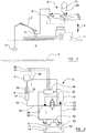
- the vessel 1 is shown in figure 1 in a configuration for lifting and lowering a load 3 via a crane 2, it is to be appreciated that the heave compensating system 6 of the present disclosure is also suitable for use in maintaining drilling or coring tools, or indeed any other equipment suspended from the vessel 1 in a substantially constant position relative to the seabed 7 and under substantially constant load as the vessel moves in heave.
- the heave compensating system 6 comprises a first hydraulic machine 9 and a second hydraulic machine 10, both of which are designed to operate as rotary pumps/motors.
- the two hydraulic machines 9, 10 are both provided in the form of over-centre rotary machines.
- the first hydraulic machine 9 has a drive shaft 11 which is directly connected to the axle of an electric motor 12 located between the two hydraulic machines 9, 10.
- the second hydraulic machine has a drive shaft 13 which is directly connected to the opposite end of the motor's axle.
- the two hydraulic machines 9, 10 are thus mechanically connected to one another in a direct 1:1 ratio, via the motor 12, for co-rotation about a common axis.
- the two hydraulic machines 9, 10 and the intermediate motor 12 will all be mounted about a single, shared, drive shaft.
- Both hydraulic machines 9, 10 are provided in fluid communication with a shared reservoir 14 for hydraulic fluid.
- the motor 24 may preferably be an asynchronous motor, although it is envisaged that variable speed motors could be used in alternative embodiments.
- the actuator 5, as is shown more clearly in figure 2 takes the form of a hydraulic ram comprising a slideably moveable piston 15 mounted within a cylinder 16. Movement of the piston 15 within the cylinder 16 is effective to lift or lower the load 3.
- the pressure side 17 of the actuator 5 is fluidly connected to the first hydraulic machine 9 via an actuator fluid line 18.
- movement of the first hydraulic machine 9 is thus effective to move the piston 15 of the actuator within the cylinder 16, and hence move the load 3 relative to the vessel.
- operation of the first hydraulic machine 9 to pump hydraulic fluid via the actuator line 18 to the actuator 5 is effective to lift the load 3.
- the second hydraulic 10 is fluidly connected to a hydraulic actuator 19 via an accumulator fluid line 20.
- the hydraulic accumulator 19 can take any convenient known form such as, for example; a piston type, a spring type, or a weight loaded type. However, it is preferred to use an accumulator of the known bladder type, in which the bladder 21 contains Nitrogen gas.
- a valve 22 is provided in a bypass fluid line 23 extending between the actuator line 18 and the accumulator line 20.
- the valve 22 is operable to move from a first, closed, position as illustrated in figure 2 to a second, open, position effective to connect the accumulator 19 and the actuator 6 directly along the fluid line 23.
- a controller 24 receives, via sensor cables 25, signals representative of; the position of the load 3 relative to the vessel from a position sensor 26; the accumulator pressure from pressure sensors 25, 26.
- the controller is also configured to receive signals representative of a wave-induced heave movement of the vessel and/or a wave induced force applied to the load, from sensors 27, 28.
- the controller preferably takes the form of a microcomputer, and is configured to control movement of the first and second hydraulic machines 9, 10, and to control the supply of motive power to the motor 12 via control cables 29, in response to said signals so as to maintain the position of, or load on, the load 3 substantially constant as the vessel moves in heave.
- FIG. 3 a simplified illustration depicts of the heave compensating system in an instant condition corresponding to downwards heave movement of the vessel, for example as the vessel falls in a wave trough.
- the controller 24 operates to detect this heave movement of the vessel and responds by driving the first hydraulic machine 9 in the manner of a pump, to pump hydraulic fluid into the compensating actuator 5, thereby lifting the load 3 to compensate for the downwards motion of the vessel.
- the first machine is driven in this manner by the second machine 10, the second machine 10 operating in the manner of a motor under the control of the controller 24, to provide torque to the interconnected drive shafts 11, 13, and drawing energy for this drive from the accumulator 19.
- Arrow 29 thus denotes the flow of energy during this drive phase of the system.
- Figure 4 depicts the heave compensating system at an instant condition corresponding to upwards heave movement of the vessel 1, for example as the vessel rises on a wave crest.
- the controller operates to detect this upwards heave movement of the vessel and responds by actuating the first hydraulic machine 9 in the manner of a motor, driven by the hydraulic pressure applied by the compensating actuator 5.
- This movement of the first hydraulic machine 9 drives the interconnected shafts 11, 13 and hence drives the second hydraulic machine 10 in the manner of a pump, increasing the pressure in the accumulator 19.
- Arrow 30 thus denotes the reversed flow of energy during this drive phase of the system.
- the vessel's heave movement in a seaway will tend to alternate continuously between upwards and downwards movement.
- the controller 24 thus operates to continuously adjust the position of the compensating actuator 5, alternating between the two drive phases explained above, as required to maintain the load in a substantially constant position relative to the seabed 7.
- This continuous operation is denoted in figure 5 , where arrow 31 denotes the alternating flow of energy between the actuator 5 and the accumulator 19.
- the electric motor 12 is therefore operable, under the control of the controller 24, to compensate for these losses by adding torque to the shafts 11, 13 as required in order to maintain the mean value of energy in the accumulator 19 substantially constant.
- the controller 24 thus continuously monitors the signals from the sensor 25 which are indicative of the pressure within the accumulator over time, and selectively energises the motor 12 (as depicted by arrow 32 in figure 5 ), during either a lifting or a lowering phase, to add energy back into the hydraulic system in the form of torque to the shafts 11, 13.
- the heave compensating system thus provides both a passive and an active function, but does so with a very simple and compact arrangement.
- the controller 24 will be configured to control the motor 12 at least partly in accordance with signals and data representative of previous cycles of vessel heave movement, or even in accordance with calculated data representative of predicted levels of energy recuperated from future heave cycles.
- figure 6 denotes the system in operation without the supply of energy to the electric motor 12, such as might be the case, for example, in the event of a power failure or outage onboard the vessel 1.
- the controller 24 and its associated circuitry will switch to be powered by an emergency generator or battery or the like, and so will remain operational.
- loss of electrical power to the motor 12 in these circumstances will preclude operation of the motor in the manner described above.
- the heave compensating system will thus revert to a purely passive mode of operation as described above, with energy flowing to and fro between the actuator 5 and the accumulator 19 without any contribution of additional torque from the motor 12.
- rotation of the shafts 11, 13 during movement of the two hydraulic machines 9, 10 in this mode will still cause the motor 12 to rotate.
- the inertia of the inoperative motor in this mode of operation acts to stabilise the rotational speed of the shafts 11, 13.
- the system will continue to operate in this passive mode for a significant but nevertheless limited period of time, but will of course result in a gradual reduction in the mean pressure of the accumulator 19 due to losses in the system no longer being compensated by the motor 12.
- the controller 24 will continue to monitor the pressure of the accumulator, via the pressure sensor 25 during operation in this passive mode.
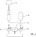
- the controller 24 is thus configured to switch the system to a back-up mode of operation in such circumstances upon detection of the pressure in the accumulator 19 falling below a predetermined threshold limit as stored in an internal memory in the controller. In this situation, the controller operates to switch the valve 22 from its closed position illustrated in figure 2 to an open position effective to open the bypass flow line 23 between the accumulator 19 and the actuator 5, thereby directly connecting the accumulator to the actuator 5 and bypassing the hydraulic machines 9, 10 as depicted in figure 7 .
- the equipment of the embodiment described above, and in particular the hydraulic equipment represented by the actuator 5, the two hydraulic machines 9, 10, the accumulator 19 and the motor 12 can be used as a hydraulic power unit for general lifting and lowering operations of the crane 2.
- the controller 24 system can be operated, under the control of the controller 24, in a non-compensating lowering mode in which the first hydraulic machine is operated in the manner of a motor, driven by the hydraulic pressure applied by the compensating actuator 5 generally as depicted in figure 4 .
- the load or tool When the load or tool has been lowered to the desired operational depth, it can then be maintained in that position by switching the system to its passive/active heave-compensating mode.
- the system When the load 3 or tool is subsequently to be lifted to the surface, the system can be switched out of the compensating mode and into a lifting mode, whereby the first hydraulic machine 9 is driven in the manner of a pump by the second hydraulic machine to lift the load generally as depicted in figure 3 .
- the heave compensating system 6 of the present disclosure can thus be conveniently combined with a hydraulic lifting arrangement aboard the vessel 1.
- machines and the motor could be interconnected via a variable ratio gear arrangement.
Claims (15)
- Hebungsausgleichssystem für ein Seefahrzeug, wobei das System Folgendes umfasst:einen Hydraulikaktuator (16), der zur Verbindung zwischen dem Wasserfahrzeug und einer an dem Wasserfahrzeug (3) aufzuhängenden Last ausgelegt ist, wobei der Aktuator (16) hydraulisch betätigbar ist, um den Abstand zwischen der Last und dem Wasserfahrzeug als Reaktion auf eine Hebebewegung des Wasserfahrzeugs zu variieren;wobei der Hydraulikaktuator (16) mit einer ersten Hydraulikvorrichtung (9) zur Betätigung durch die erste Hydraulikvorrichtung (9) in Fluid-Verbindung ist;wobei das System ferner eine zweite Hydraulikvorrichtung (10) umfasst, die mit einem Hydraulikspeicher (19) in Fluid-Verbindung ist;einen Elektromotor; undeine Steuerungseinheit (24), die ausgelegt ist, um eine hydraulische Bewegung der ersten (9) und der zweiten (10) Hydraulikvorrichtung und Leistung für den Elektromotor (12) als Reaktion auf ein oder mehrere Signale, die für eine welleninduzierte Hebebewegung des Wasserfahrzeugs und/oder eine auf die Last (3) ausgeübte, welleninduzierte Kraft repräsentativ sind, zu steuern;dadurch gekennzeichnet,dass die erste (9) und die zweite (10) Hydraulikvorrichtung mechanisch miteinander verbunden sind und beide auch mit dem Elektromotor (12) mechanisch verbunden sind; wobei die erste (9) und die zweite (10) Hydraulikvorrichtung so ausgestaltet sind, dass sie zwischen einem Betrieb in einer ersten Antriebsphase und einer zweiten Antriebsphase wechseln, wenn die welleninduzierte Hebebewegung des Wasserfahrzeugs und/oder die auf die Last (3) ausgeübte, welleninduzierte Kraft zwischen einer Aufwärtsbewegung und einer Abwärtsbewegung wechselt,wobei in der ersten Antriebsphase die erste Hydraulikvorrichtung (9) als eine Pumpe arbeitet und die zweite Hydraulikvorrichtung (10) als ein Motor arbeitet, undwobei in der zweiten Antriebsphase die erste Hydraulikvorrichtung (9) als ein Motor arbeitet und die zweite Hydraulikvorrichtung (10) als eine Pumpe arbeitet.
- System gemäß Anspruch 1, wobei die zwei Hydraulikvorrichtungen (9, 10) und der Elektromotor über ein direktes Verhältnis von 1:1 miteinander verbunden sind.
- System gemäß Anspruch 1 oder Anspruch 2, wobei sowohl die zwei Hydraulikvorrichtungen (9, 10) als auch der Elektromotor (12) um eine gemeinsame Antriebswelle herum befestigt sind.
- System gemäß Anspruch 1 oder Anspruch 2, wobei jede Hydraulikvorrichtung eine jeweilige Antriebswelle (11, 13) aufweist, wobei die zwei Wellen im Wesentlichen koaxial und über den Motor miteinander verbunden sind, wobei der Motor zwischen den Antriebswellen zum Rotieren um die Achse der Wellen angeordnet ist.
- System gemäß einem der vorangegangenen Ansprüche, wobei der Elektromotor ein asynchroner Motor ist.
- System gemäß einem der vorangegangenen Ansprüche, ferner umfassend ein Ventil (22), das in einer Fluidleitung zwischen dem Akkumulator (19) und dem Aktuator (5) angeordnet ist, wobei das Ventil ausgelegt ist, sich zwischen einer ersten Position, in welcher der Akkumulator und der Aktuator fluidisch voneinander getrennt sind, und einer zweiten Position, in welcher der Akkumulator und der Aktuator über die Fluidleitung in Fluid-Verbindung sind, zu bewegen.
- System gemäß Anspruch 6, wobei die Steuerungseinheit (24) ausgelegt ist, die Funktion des Ventils (22) in Abhängigkeit von einem Signal, das für den Hydraulikdruck im Akkumulator repräsentativ ist, zu steuern, wobei die Steuerungseinheit konfiguriert ist, das Ventil von der ersten Position in die zweite Position als Reaktion auf das Absinken des Drucks auf einen vorbestimmten Schwellenwert zu bewegen.
- System gemäß einem der vorangegangenen Ansprüche, wobei die Steuerungseinheit (24) ausgelegt ist, ein Signal, das für den Hydraulikdruck im Akkumulator repräsentativ ist, zu empfangen und eine Leistung für den Elektromotor als Reaktion darauf zu steuern.
- System gemäß einem der vorangegangenen Ansprüche, wobei die Steuerungseinheit (24) ausgelegt ist, ein Signal, das für die Position der Last relativ zu dem Wasserfahrzeug repräsentativ ist, zu empfangen und eine Bewegung der ersten und der zweiten Hydraulikvorrichtung als Reaktion darauf zu steuern.
- System gemäß einem der vorangegangenen Ansprüche, das ausgelegt ist, eine im Wesentlichen konstante Stützkraft auf der an dem Wasserfahrzeug (1) aufgehängten Last während einer Hebebewegung des Wasserfahrzeugs aufrechtzuerhalten.
- System gemäß einem der Ansprüche 1 bis 9, das ausgelegt ist, die an dem Wasserfahrzeug aufgehängte Last (3) in einer im Wesentlichen konstanten Position während einer Hebebewegung des Wasserfahrzeugs aufrechtzuerhalten.
- Verfahren zum Betreiben eines Hebungsausgleichssystems gemäß einem der vorangegangenen Ansprüche in einem Aktivmodus, in dem die Steuerungseinheit (24) eine Erregung des Elektromotors (12) aktiv steuert.
- Verfahren gemäß Anspruch 12, wobei eine Leistung für den Elektromotor in Abhängigkeit von dem Hydraulikdruck im Akkumulator im Aktivmodus gesteuert wird.
- Verfahren zum Betreiben eines Hebungsausgleichssystems gemäß einem der vorangegangenen Ansprüche 1 bis 11 in einem Passivmodus, in dem der Motor nicht erregt wird.
- Verfahren zum Betreiben eines Hebungsausgleichssystems gemäß Anspruch 6 oder Anspruch 7, wobei das Ventil von seiner ersten Position in seine zweite Position bewegt wird, um den Aktuator und den Akkumulator fluidisch miteinander zu verbinden, wodurch die erste und die zweite Hydraulikvorrichtung umgangen werden, und zwar als Reaktion auf den Druck innerhalb des Akkumulators, der unter einen vorbestimmten Schwellenwert absinkt.
Applications Claiming Priority (2)
| Application Number | Priority Date | Filing Date | Title |
|---|---|---|---|
| GB1019555.0A GB2485570A (en) | 2010-11-18 | 2010-11-18 | Heave compensating system |
| PCT/GB2011/001467 WO2012066268A2 (en) | 2010-11-18 | 2011-10-11 | A heave compensating system |
Publications (2)
| Publication Number | Publication Date |
|---|---|
| EP2640657A2 EP2640657A2 (de) | 2013-09-25 |
| EP2640657B1 true EP2640657B1 (de) | 2018-11-21 |
Family
ID=43431660
Family Applications (1)
| Application Number | Title | Priority Date | Filing Date |
|---|---|---|---|
| EP11773512.6A Active EP2640657B1 (de) | 2010-11-18 | 2011-10-11 | Hebungsausgleichssystem |
Country Status (7)
| Country | Link |
|---|---|
| US (1) | US9267340B2 (de) |
| EP (1) | EP2640657B1 (de) |
| KR (1) | KR101839985B1 (de) |
| BR (1) | BR112013011835B8 (de) |
| GB (1) | GB2485570A (de) |
| RU (1) | RU2569511C2 (de) |
| WO (1) | WO2012066268A2 (de) |
Families Citing this family (15)
| Publication number | Priority date | Publication date | Assignee | Title |
|---|---|---|---|---|
| ES2645258T3 (es) * | 2011-03-28 | 2017-12-04 | Ocean Power Technologies, Inc. | Convertidor de energía de las olas con resorte hidráulico giratorio |
| DE102012017004A1 (de) * | 2012-08-28 | 2014-03-06 | Hydac Technology Gmbh | Hydraulisches Energierückgewinnungssystem |
| KR101462582B1 (ko) * | 2013-01-09 | 2014-11-17 | 주식회사 칸 | 해양구조물의 수직운동보상기 제어시스템 |
| KR101587478B1 (ko) | 2014-07-14 | 2016-01-22 | 대우조선해양 주식회사 | 해양구조물의 히브모션 댐핑기구 |
| GB201419394D0 (en) | 2014-10-31 | 2014-12-17 | Saipem Spa | Offshore lifting of a load with heave compensation |
| EP3225855B1 (de) * | 2014-11-24 | 2021-08-25 | Xuzhou Heavy Machinery Co., Ltd. | Verfahren und system zur rückgewinnung und verwendung von arbeitsenergie eines krans sowie kran |
| DE102015222910A1 (de) * | 2014-11-27 | 2016-06-02 | Robert Bosch Gmbh | Bewegungsausgleichsvorrichtung |
| NL2014318B1 (en) * | 2015-02-20 | 2016-10-13 | Boskalis Bv Baggermaatschappij | Vessel with heave compensation system. |
| EP3144543A1 (de) * | 2015-09-17 | 2017-03-22 | Robert Bosch Gmbh | Vorrichtung und verfahren zur steuerung eines sichereitsventilaggregats |
| MX2018010086A (es) * | 2016-02-22 | 2019-06-06 | Safelink As | Compensador de desplazamiento movil activo para entorno submarino. |
| DE102016005477A1 (de) * | 2016-05-03 | 2017-11-09 | Hycom B.V. | Ausgleichsvorrichtung zum Beibehalten von vorgebbaren Soll-Positionen einer handhabbaren Last |
| CN106364630B (zh) * | 2016-09-22 | 2018-07-24 | 华中科技大学 | 一种有缆水下机器人半主动升沉补偿系统 |
| EP3301062B1 (de) | 2016-10-03 | 2021-11-03 | National Oilwell Varco Norway AS | In einem seeschiff oder einer plattform angeordnetes system, wie etwa zur bereitstellung von seegangskompensation und heben |
| EP4080062A1 (de) * | 2021-04-23 | 2022-10-26 | Norrhydro OY | Elektrohydraulisches stellglied und verfahren |
| CN113738714A (zh) * | 2021-08-04 | 2021-12-03 | 温州大学 | 一种深海机器人索缆系统升沉补偿装置 |
Family Cites Families (12)
| Publication number | Priority date | Publication date | Assignee | Title |
|---|---|---|---|---|
| US3653636A (en) * | 1970-02-09 | 1972-04-04 | Exxon Production Research Co | Wave motion compensation system for suspending well equipment from a floating vessel |
| US3905580A (en) * | 1973-10-09 | 1975-09-16 | Global Marine Inc | Heave compensator |
| US4176722A (en) * | 1978-03-15 | 1979-12-04 | Global Marine, Inc. | Marine riser system with dual purpose lift and heave compensator mechanism |
| GB2055342B (en) * | 1979-07-27 | 1983-10-26 | Vickers Offshore Projects & De | Maintaining constant tension |
| FR2597081B1 (fr) | 1986-04-10 | 1988-06-10 | Alsthom | Dispositif de mise en tension d'un cable de traction lie a l'une de ses extremites a l'extremite superieure d'un tube dont l'extremite inferieure est fixee au fond de la mer |
| US5209302A (en) | 1991-10-04 | 1993-05-11 | Retsco, Inc. | Semi-active heave compensation system for marine vessels |
| US6378301B2 (en) * | 1996-09-25 | 2002-04-30 | Komatsu Ltd. | Pressurized fluid recovery/reutilization system |
| RU2262464C2 (ru) * | 2003-06-25 | 2005-10-20 | Закрытое акционерное общество "Центральный Научно-исследовательский Институт Судового Машиностроения" (ЗАО "ЦНИИ СМ") | Гидравлическая система судового крана |
| NO322172B1 (no) | 2004-05-21 | 2006-08-21 | Fmc Kongsberg Subsea As | Anordning i forbindelse med hivkompensering av et trykksatt stigeror forlopende mellom en havbunnsinstallasjon og en flytende enhet. |
| CN100427771C (zh) * | 2006-12-14 | 2008-10-22 | 浙江大学 | 一种液压配重可变的节能液压升降系统 |
| NO336258B1 (no) * | 2007-09-19 | 2015-07-06 | Nat Oilwell Varco Norway As | Fremgangsmåte og anordning for løftkompensering. |
| DE602008004099D1 (de) * | 2008-04-29 | 2011-02-03 | Parker Hannifin Ab | Anordnung zum Bedienen einer hydraulischen Vorrichtung |
-
2010
- 2010-11-18 GB GB1019555.0A patent/GB2485570A/en not_active Withdrawn
-
2011
- 2011-10-11 RU RU2013122781/11A patent/RU2569511C2/ru active
- 2011-10-11 US US13/988,281 patent/US9267340B2/en active Active
- 2011-10-11 WO PCT/GB2011/001467 patent/WO2012066268A2/en active Application Filing
- 2011-10-11 BR BR112013011835A patent/BR112013011835B8/pt active IP Right Grant
- 2011-10-11 KR KR1020137015123A patent/KR101839985B1/ko active IP Right Grant
- 2011-10-11 EP EP11773512.6A patent/EP2640657B1/de active Active
Non-Patent Citations (1)
| Title |
|---|
| None * |
Also Published As
| Publication number | Publication date |
|---|---|
| RU2013122781A (ru) | 2014-12-27 |
| RU2569511C2 (ru) | 2015-11-27 |
| KR20130113482A (ko) | 2013-10-15 |
| EP2640657A2 (de) | 2013-09-25 |
| GB2485570A (en) | 2012-05-23 |
| BR112013011835A2 (pt) | 2016-08-16 |
| KR101839985B1 (ko) | 2018-03-20 |
| WO2012066268A2 (en) | 2012-05-24 |
| US9267340B2 (en) | 2016-02-23 |
| BR112013011835B8 (pt) | 2022-05-10 |
| US20130312979A1 (en) | 2013-11-28 |
| GB201019555D0 (en) | 2010-12-29 |
| BR112013011835B1 (pt) | 2021-01-26 |
| WO2012066268A3 (en) | 2013-05-16 |
Similar Documents
| Publication | Publication Date | Title |
|---|---|---|
| EP2640657B1 (de) | Hebungsausgleichssystem | |
| US4962817A (en) | Active reference system | |
| US10081988B2 (en) | Heave compensation winches | |
| US5894895A (en) | Heave compensator for drill ships | |
| AU2017271305B2 (en) | Transportable inline heave compensator | |
| US10689922B2 (en) | System and method for providing tension or heave compensation in an offshore drilling environment | |
| US8297597B2 (en) | Method for lift compensation | |
| EP3155206B1 (de) | Winden und hubsysteme mit seegangskompensierung | |
| CN109422204B (zh) | 一种海上作业用布放回收系统 | |
| CA2462071C (en) | Multi-purpose coiled tubing handling system | |
| US3905580A (en) | Heave compensator | |
| EP3287589A1 (de) | Schwimmendes offshore-schiff und verfahren zum betrieb davon | |
| WO2011145947A1 (en) | An apparatus and method for recuperation of hydraulic energy | |
| US11059547B2 (en) | System arranged on a marine vessel or platform, such as for providing heave compensation and hoisting | |
| EP3059199B1 (de) | Schiff mit wellenausgleichsystem | |
| EP3227520B1 (de) | Seegangskompensationsverfahren | |
| NO342595B1 (en) | Rotary inline heave compensator | |
| EP3882123A1 (de) | Verfahren zur gewinnung von energie aus einer hebestruktur | |
| GB2571267A (en) | Offshore energy management system | |
| KR20180036204A (ko) | 회전식 유압 윈치 타입 히브모션 보상 시스템 |
Legal Events
| Date | Code | Title | Description |
|---|---|---|---|
| PUAI | Public reference made under article 153(3) epc to a published international application that has entered the european phase |
Free format text: ORIGINAL CODE: 0009012 |
|
| 17P | Request for examination filed |
Effective date: 20130429 |
|
| AK | Designated contracting states |
Kind code of ref document: A2 Designated state(s): AL AT BE BG CH CY CZ DE DK EE ES FI FR GB GR HR HU IE IS IT LI LT LU LV MC MK MT NL NO PL PT RO RS SE SI SK SM TR |
|
| DAX | Request for extension of the european patent (deleted) | ||
| STAA | Information on the status of an ep patent application or granted ep patent |
Free format text: STATUS: EXAMINATION IS IN PROGRESS |
|
| 17Q | First examination report despatched |
Effective date: 20170215 |
|
| GRAP | Despatch of communication of intention to grant a patent |
Free format text: ORIGINAL CODE: EPIDOSNIGR1 |
|
| STAA | Information on the status of an ep patent application or granted ep patent |
Free format text: STATUS: GRANT OF PATENT IS INTENDED |
|
| INTG | Intention to grant announced |
Effective date: 20180514 |
|
| GRAS | Grant fee paid |
Free format text: ORIGINAL CODE: EPIDOSNIGR3 |
|
| GRAA | (expected) grant |
Free format text: ORIGINAL CODE: 0009210 |
|
| STAA | Information on the status of an ep patent application or granted ep patent |
Free format text: STATUS: THE PATENT HAS BEEN GRANTED |
|
| AK | Designated contracting states |
Kind code of ref document: B1 Designated state(s): AL AT BE BG CH CY CZ DE DK EE ES FI FR GB GR HR HU IE IS IT LI LT LU LV MC MK MT NL NO PL PT RO RS SE SI SK SM TR |
|
| REG | Reference to a national code |
Ref country code: CH Ref legal event code: EP |
|
| REG | Reference to a national code |
Ref country code: IE Ref legal event code: FG4D |
|
| REG | Reference to a national code |
Ref country code: DE Ref legal event code: R096 Ref document number: 602011054105 Country of ref document: DE |
|
| REG | Reference to a national code |
Ref country code: AT Ref legal event code: REF Ref document number: 1067288 Country of ref document: AT Kind code of ref document: T Effective date: 20181215 |
|
| REG | Reference to a national code |
Ref country code: NL Ref legal event code: MP Effective date: 20181121 |
|
| REG | Reference to a national code |
Ref country code: AT Ref legal event code: MK05 Ref document number: 1067288 Country of ref document: AT Kind code of ref document: T Effective date: 20181121 Ref country code: NO Ref legal event code: T2 Effective date: 20181121 |
|
| PG25 | Lapsed in a contracting state [announced via postgrant information from national office to epo] |
Ref country code: IS Free format text: LAPSE BECAUSE OF FAILURE TO SUBMIT A TRANSLATION OF THE DESCRIPTION OR TO PAY THE FEE WITHIN THE PRESCRIBED TIME-LIMIT Effective date: 20190321 Ref country code: ES Free format text: LAPSE BECAUSE OF FAILURE TO SUBMIT A TRANSLATION OF THE DESCRIPTION OR TO PAY THE FEE WITHIN THE PRESCRIBED TIME-LIMIT Effective date: 20181121 Ref country code: AT Free format text: LAPSE BECAUSE OF FAILURE TO SUBMIT A TRANSLATION OF THE DESCRIPTION OR TO PAY THE FEE WITHIN THE PRESCRIBED TIME-LIMIT Effective date: 20181121 Ref country code: LT Free format text: LAPSE BECAUSE OF FAILURE TO SUBMIT A TRANSLATION OF THE DESCRIPTION OR TO PAY THE FEE WITHIN THE PRESCRIBED TIME-LIMIT Effective date: 20181121 Ref country code: HR Free format text: LAPSE BECAUSE OF FAILURE TO SUBMIT A TRANSLATION OF THE DESCRIPTION OR TO PAY THE FEE WITHIN THE PRESCRIBED TIME-LIMIT Effective date: 20181121 Ref country code: BG Free format text: LAPSE BECAUSE OF FAILURE TO SUBMIT A TRANSLATION OF THE DESCRIPTION OR TO PAY THE FEE WITHIN THE PRESCRIBED TIME-LIMIT Effective date: 20190221 Ref country code: FI Free format text: LAPSE BECAUSE OF FAILURE TO SUBMIT A TRANSLATION OF THE DESCRIPTION OR TO PAY THE FEE WITHIN THE PRESCRIBED TIME-LIMIT Effective date: 20181121 Ref country code: LV Free format text: LAPSE BECAUSE OF FAILURE TO SUBMIT A TRANSLATION OF THE DESCRIPTION OR TO PAY THE FEE WITHIN THE PRESCRIBED TIME-LIMIT Effective date: 20181121 |
|
| PG25 | Lapsed in a contracting state [announced via postgrant information from national office to epo] |
Ref country code: RS Free format text: LAPSE BECAUSE OF FAILURE TO SUBMIT A TRANSLATION OF THE DESCRIPTION OR TO PAY THE FEE WITHIN THE PRESCRIBED TIME-LIMIT Effective date: 20181121 Ref country code: SE Free format text: LAPSE BECAUSE OF FAILURE TO SUBMIT A TRANSLATION OF THE DESCRIPTION OR TO PAY THE FEE WITHIN THE PRESCRIBED TIME-LIMIT Effective date: 20181121 Ref country code: AL Free format text: LAPSE BECAUSE OF FAILURE TO SUBMIT A TRANSLATION OF THE DESCRIPTION OR TO PAY THE FEE WITHIN THE PRESCRIBED TIME-LIMIT Effective date: 20181121 Ref country code: PT Free format text: LAPSE BECAUSE OF FAILURE TO SUBMIT A TRANSLATION OF THE DESCRIPTION OR TO PAY THE FEE WITHIN THE PRESCRIBED TIME-LIMIT Effective date: 20190321 Ref country code: NL Free format text: LAPSE BECAUSE OF FAILURE TO SUBMIT A TRANSLATION OF THE DESCRIPTION OR TO PAY THE FEE WITHIN THE PRESCRIBED TIME-LIMIT Effective date: 20181121 Ref country code: GR Free format text: LAPSE BECAUSE OF FAILURE TO SUBMIT A TRANSLATION OF THE DESCRIPTION OR TO PAY THE FEE WITHIN THE PRESCRIBED TIME-LIMIT Effective date: 20190222 |
|
| PG25 | Lapsed in a contracting state [announced via postgrant information from national office to epo] |
Ref country code: PL Free format text: LAPSE BECAUSE OF FAILURE TO SUBMIT A TRANSLATION OF THE DESCRIPTION OR TO PAY THE FEE WITHIN THE PRESCRIBED TIME-LIMIT Effective date: 20181121 Ref country code: DK Free format text: LAPSE BECAUSE OF FAILURE TO SUBMIT A TRANSLATION OF THE DESCRIPTION OR TO PAY THE FEE WITHIN THE PRESCRIBED TIME-LIMIT Effective date: 20181121 Ref country code: IT Free format text: LAPSE BECAUSE OF FAILURE TO SUBMIT A TRANSLATION OF THE DESCRIPTION OR TO PAY THE FEE WITHIN THE PRESCRIBED TIME-LIMIT Effective date: 20181121 Ref country code: CZ Free format text: LAPSE BECAUSE OF FAILURE TO SUBMIT A TRANSLATION OF THE DESCRIPTION OR TO PAY THE FEE WITHIN THE PRESCRIBED TIME-LIMIT Effective date: 20181121 |
|
| REG | Reference to a national code |
Ref country code: DE Ref legal event code: R097 Ref document number: 602011054105 Country of ref document: DE |
|
| PG25 | Lapsed in a contracting state [announced via postgrant information from national office to epo] |
Ref country code: SM Free format text: LAPSE BECAUSE OF FAILURE TO SUBMIT A TRANSLATION OF THE DESCRIPTION OR TO PAY THE FEE WITHIN THE PRESCRIBED TIME-LIMIT Effective date: 20181121 Ref country code: EE Free format text: LAPSE BECAUSE OF FAILURE TO SUBMIT A TRANSLATION OF THE DESCRIPTION OR TO PAY THE FEE WITHIN THE PRESCRIBED TIME-LIMIT Effective date: 20181121 Ref country code: RO Free format text: LAPSE BECAUSE OF FAILURE TO SUBMIT A TRANSLATION OF THE DESCRIPTION OR TO PAY THE FEE WITHIN THE PRESCRIBED TIME-LIMIT Effective date: 20181121 Ref country code: SK Free format text: LAPSE BECAUSE OF FAILURE TO SUBMIT A TRANSLATION OF THE DESCRIPTION OR TO PAY THE FEE WITHIN THE PRESCRIBED TIME-LIMIT Effective date: 20181121 |
|
| PLBE | No opposition filed within time limit |
Free format text: ORIGINAL CODE: 0009261 |
|
| STAA | Information on the status of an ep patent application or granted ep patent |
Free format text: STATUS: NO OPPOSITION FILED WITHIN TIME LIMIT |
|
| 26N | No opposition filed |
Effective date: 20190822 |
|
| PG25 | Lapsed in a contracting state [announced via postgrant information from national office to epo] |
Ref country code: SI Free format text: LAPSE BECAUSE OF FAILURE TO SUBMIT A TRANSLATION OF THE DESCRIPTION OR TO PAY THE FEE WITHIN THE PRESCRIBED TIME-LIMIT Effective date: 20181121 |
|
| PG25 | Lapsed in a contracting state [announced via postgrant information from national office to epo] |
Ref country code: TR Free format text: LAPSE BECAUSE OF FAILURE TO SUBMIT A TRANSLATION OF THE DESCRIPTION OR TO PAY THE FEE WITHIN THE PRESCRIBED TIME-LIMIT Effective date: 20181121 |
|
| REG | Reference to a national code |
Ref country code: DE Ref legal event code: R119 Ref document number: 602011054105 Country of ref document: DE |
|
| PG25 | Lapsed in a contracting state [announced via postgrant information from national office to epo] |
Ref country code: MC Free format text: LAPSE BECAUSE OF FAILURE TO SUBMIT A TRANSLATION OF THE DESCRIPTION OR TO PAY THE FEE WITHIN THE PRESCRIBED TIME-LIMIT Effective date: 20181121 |
|
| REG | Reference to a national code |
Ref country code: CH Ref legal event code: PL |
|
| PG25 | Lapsed in a contracting state [announced via postgrant information from national office to epo] |
Ref country code: LI Free format text: LAPSE BECAUSE OF NON-PAYMENT OF DUE FEES Effective date: 20191031 Ref country code: LU Free format text: LAPSE BECAUSE OF NON-PAYMENT OF DUE FEES Effective date: 20191011 Ref country code: DE Free format text: LAPSE BECAUSE OF NON-PAYMENT OF DUE FEES Effective date: 20200501 Ref country code: CH Free format text: LAPSE BECAUSE OF NON-PAYMENT OF DUE FEES Effective date: 20191031 |
|
| REG | Reference to a national code |
Ref country code: BE Ref legal event code: MM Effective date: 20191031 |
|
| PG25 | Lapsed in a contracting state [announced via postgrant information from national office to epo] |
Ref country code: BE Free format text: LAPSE BECAUSE OF NON-PAYMENT OF DUE FEES Effective date: 20191031 |
|
| PG25 | Lapsed in a contracting state [announced via postgrant information from national office to epo] |
Ref country code: IE Free format text: LAPSE BECAUSE OF NON-PAYMENT OF DUE FEES Effective date: 20191011 Ref country code: FR Free format text: LAPSE BECAUSE OF NON-PAYMENT OF DUE FEES Effective date: 20191031 |
|
| PG25 | Lapsed in a contracting state [announced via postgrant information from national office to epo] |
Ref country code: CY Free format text: LAPSE BECAUSE OF FAILURE TO SUBMIT A TRANSLATION OF THE DESCRIPTION OR TO PAY THE FEE WITHIN THE PRESCRIBED TIME-LIMIT Effective date: 20181121 |
|
| PG25 | Lapsed in a contracting state [announced via postgrant information from national office to epo] |
Ref country code: MT Free format text: LAPSE BECAUSE OF FAILURE TO SUBMIT A TRANSLATION OF THE DESCRIPTION OR TO PAY THE FEE WITHIN THE PRESCRIBED TIME-LIMIT Effective date: 20181121 Ref country code: HU Free format text: LAPSE BECAUSE OF FAILURE TO SUBMIT A TRANSLATION OF THE DESCRIPTION OR TO PAY THE FEE WITHIN THE PRESCRIBED TIME-LIMIT; INVALID AB INITIO Effective date: 20111011 |
|
| PG25 | Lapsed in a contracting state [announced via postgrant information from national office to epo] |
Ref country code: MK Free format text: LAPSE BECAUSE OF FAILURE TO SUBMIT A TRANSLATION OF THE DESCRIPTION OR TO PAY THE FEE WITHIN THE PRESCRIBED TIME-LIMIT Effective date: 20181121 |
|
| PGFP | Annual fee paid to national office [announced via postgrant information from national office to epo] |
Ref country code: GB Payment date: 20230831 Year of fee payment: 13 |
|
| PGFP | Annual fee paid to national office [announced via postgrant information from national office to epo] |
Ref country code: NO Payment date: 20231010 Year of fee payment: 13 |