EP2640657B1 - A heave compensating system - Google Patents
A heave compensating system Download PDFInfo
- Publication number
- EP2640657B1 EP2640657B1 EP11773512.6A EP11773512A EP2640657B1 EP 2640657 B1 EP2640657 B1 EP 2640657B1 EP 11773512 A EP11773512 A EP 11773512A EP 2640657 B1 EP2640657 B1 EP 2640657B1
- Authority
- EP
- European Patent Office
- Prior art keywords
- hydraulic
- vessel
- accumulator
- load
- motor
- Prior art date
- Legal status (The legal status is an assumption and is not a legal conclusion. Google has not performed a legal analysis and makes no representation as to the accuracy of the status listed.)
- Active
Links
- 230000033001 locomotion Effects 0.000 claims description 33
- 239000012530 fluid Substances 0.000 claims description 14
- 230000004044 response Effects 0.000 claims description 13
- 238000000034 method Methods 0.000 claims description 7
- 238000005553 drilling Methods 0.000 description 4
- 238000013016 damping Methods 0.000 description 2
- 230000006870 function Effects 0.000 description 2
- 230000004048 modification Effects 0.000 description 2
- 238000012986 modification Methods 0.000 description 2
- IJGRMHOSHXDMSA-UHFFFAOYSA-N Atomic nitrogen Chemical compound N#N IJGRMHOSHXDMSA-UHFFFAOYSA-N 0.000 description 1
- 230000009471 action Effects 0.000 description 1
- 230000004075 alteration Effects 0.000 description 1
- 230000005540 biological transmission Effects 0.000 description 1
- 238000004891 communication Methods 0.000 description 1
- 238000005056 compaction Methods 0.000 description 1
- 238000001514 detection method Methods 0.000 description 1
- 229910001873 dinitrogen Inorganic materials 0.000 description 1
- 230000009977 dual effect Effects 0.000 description 1
- 230000000694 effects Effects 0.000 description 1
- 229930195733 hydrocarbon Natural products 0.000 description 1
- 150000002430 hydrocarbons Chemical class 0.000 description 1
- 230000000670 limiting effect Effects 0.000 description 1
- 230000007246 mechanism Effects 0.000 description 1
- 230000009467 reduction Effects 0.000 description 1
- 230000000284 resting effect Effects 0.000 description 1
- 230000000717 retained effect Effects 0.000 description 1
- 230000000630 rising effect Effects 0.000 description 1
- 230000003068 static effect Effects 0.000 description 1
- 230000003313 weakening effect Effects 0.000 description 1
Images


Classifications
-
- E—FIXED CONSTRUCTIONS
- E21—EARTH DRILLING; MINING
- E21B—EARTH DRILLING, e.g. DEEP DRILLING; OBTAINING OIL, GAS, WATER, SOLUBLE OR MELTABLE MATERIALS OR A SLURRY OF MINERALS FROM WELLS
- E21B19/00—Handling rods, casings, tubes or the like outside the borehole, e.g. in the derrick; Apparatus for feeding the rods or cables
- E21B19/002—Handling rods, casings, tubes or the like outside the borehole, e.g. in the derrick; Apparatus for feeding the rods or cables specially adapted for underwater drilling
- E21B19/004—Handling rods, casings, tubes or the like outside the borehole, e.g. in the derrick; Apparatus for feeding the rods or cables specially adapted for underwater drilling supporting a riser from a drilling or production platform
- E21B19/006—Handling rods, casings, tubes or the like outside the borehole, e.g. in the derrick; Apparatus for feeding the rods or cables specially adapted for underwater drilling supporting a riser from a drilling or production platform including heave compensators
-
- B—PERFORMING OPERATIONS; TRANSPORTING
- B66—HOISTING; LIFTING; HAULING
- B66C—CRANES; LOAD-ENGAGING ELEMENTS OR DEVICES FOR CRANES, CAPSTANS, WINCHES, OR TACKLES
- B66C13/00—Other constructional features or details
- B66C13/02—Devices for facilitating retrieval of floating objects, e.g. for recovering crafts from water
-
- B—PERFORMING OPERATIONS; TRANSPORTING
- B66—HOISTING; LIFTING; HAULING
- B66D—CAPSTANS; WINCHES; TACKLES, e.g. PULLEY BLOCKS; HOISTS
- B66D1/00—Rope, cable, or chain winding mechanisms; Capstans
- B66D1/28—Other constructional details
- B66D1/40—Control devices
- B66D1/48—Control devices automatic
- B66D1/52—Control devices automatic for varying rope or cable tension, e.g. when recovering craft from water
- B66D1/525—Control devices automatic for varying rope or cable tension, e.g. when recovering craft from water electrical
-
- E—FIXED CONSTRUCTIONS
- E21—EARTH DRILLING; MINING
- E21B—EARTH DRILLING, e.g. DEEP DRILLING; OBTAINING OIL, GAS, WATER, SOLUBLE OR MELTABLE MATERIALS OR A SLURRY OF MINERALS FROM WELLS
- E21B19/00—Handling rods, casings, tubes or the like outside the borehole, e.g. in the derrick; Apparatus for feeding the rods or cables
- E21B19/08—Apparatus for feeding the rods or cables; Apparatus for increasing or decreasing the pressure on the drilling tool; Apparatus for counterbalancing the weight of the rods
- E21B19/09—Apparatus for feeding the rods or cables; Apparatus for increasing or decreasing the pressure on the drilling tool; Apparatus for counterbalancing the weight of the rods specially adapted for drilling underwater formations from a floating support using heave compensators supporting the drill string
Landscapes
- Engineering & Computer Science (AREA)
- Mechanical Engineering (AREA)
- Life Sciences & Earth Sciences (AREA)
- Geology (AREA)
- Mining & Mineral Resources (AREA)
- Physics & Mathematics (AREA)
- Environmental & Geological Engineering (AREA)
- Fluid Mechanics (AREA)
- General Life Sciences & Earth Sciences (AREA)
- Geochemistry & Mineralogy (AREA)
- Fluid-Pressure Circuits (AREA)
Description
- The present invention relates to a heave compensating system, and more particularly relates to a heave compensating system for a marine vessel.
- As is well known, the search for hydrocarbons through the seabed often involves the use of floating marine vessels such as drill-ships or floating marine platforms. The use of floating vessels of this type is generally considered advantageous over the alternative of using fixed platforms resting on the seabed during exploratory operations as they are more readily moveable from site to site.
- However, a problem associated with floating vessels used to drill into the seabed or to take cores from the seabed during such exploratory operations, is that the vessels are subjected to upward and downward heave motions due to wave action. A coring or drilling tool is typically carried at the lower end of a string or drill pipe suspended from the vessel. During coring operations, if no compensation is made for the heaving motion of the vessel above, very substantial variations can result in the force applied to the coring tool in the seabed, and this can result in unpredictable compactions or weakenings in the core retrieved the tool, thereby destroying the core or at least reducing its effectiveness for analysis. During drilling operations, heave-induced load variations on a drill bit are known to accelerate the wear of the bit. As will be appreciated, if a vessel is caused to move in heave to an excessive degree, for example in rough sea, very significant damage can be caused to such tools. It can also be important to compensate for the heave motion of a floating vessel when performing other types of hoisting operation from the vessel.
- Heave compensating systems have therefore been proposed and are generally used on such vessels to maintain a substantially constant force on the tools, and optionally to maintain the tools in a substantially constant position, as the vessel rises and falls in heave. Previously proposed heave compensator systems generally comprise a motion-compensating hydraulic cylinder associated with the crown block or the travelling block of a derrick arrangement mounted on the vessel and from which the drill string or other tool or load is suspended. The hydraulic cylinder is fluidly connected to a hydraulic accumulator, accumulator and is driven by the flow of the hydraulic fluid between the cylinder and the accumulator. Such a system is purely passive in nature.
- In a purely passive arrangement of the type described above, the nominal pressure charge of the accumulator determines the nominal hydraulic pressure of the compensating cylinder, which in turn determines the magnitude of the load suspended from the vessel which can be held substantially constant despite heaving motion of the vessel. The accumulator's precharge pressure must therefore be adjusted to balance the static load whose motion is to be compensated. However, prior art systems of this general type are known to exhibit substantial force variations due to the pressure-dependency of the accumulator on its charge. These variations can be tolerated for systems such as a so-called dead-line compensator, but require further compensation in other systems, such so-called crown mounted compensators. In such systems, this further compensation is generally achieved via the use of mechanical, position-dependant transmissions. Nevertheless, whilst such arrangements can reduce the accumulator charge-dependant force variations, they cannot readily compensate for friction damping and inertia effects. It is therefore common practice to add an active heave compensator arrangement to compensate for these force variations in the passive arrangement.
- However, combined passive/active heave compensator arrangements can be complicated, expensive, bulky and have limited operational modes.
-
US 4176 722 A , which is considered the closest prior art, discloses a marine riser system with dual purpose lift and heave compensator mechanism .US 5209 302 A discloses a semi-active heave compensation system for marine vessels.GB 2188 899 A - It is therefore an object of the present invention to provide an improved heave compensating system.
- According to a first aspect of the present invention, there is provided a heave compensating system according to
claim 1. - The system is preferably configured to maintain a substantially constant support force on a load suspended from the vessel despite heaving movement of the vessel.
- Preferably, the two hydraulic machines and the electric motor are interconnected via a direct 1:1 ratio. However, the hydraulic machines and the motor can be interconnected via different ratios.
- Advantageously, the two hydraulic machines and the electric motor are all mounted about a common drive shaft.
- Conveniently, said motor is mounted between the two hydraulic machines.
- Alternatively, both said hydraulic machines are located to the same side of the motor.
- Preferably, each said hydraulic machine has a respective drive shaft, the two shafts being substantially co-axial and interconnected via said motor, the motor being arranged between said drive shafts for rotation about the axis of said shafts.
- Advantageously, the electric motor is an asynchronous motor.
- Alternatively, the electric motor is a variable speed motor.
- Conveniently, the system further comprises a valve arranged in a fluid line between the accumulator and the actuator, the valve being operable to move between a first position in which the accumulator and the actuator are fluidly isolated from one another, and a second position in which the accumulator and the actuator are fluidly connected via the fluid line.
- Preferably, the controller is arranged to control operation of the valve in dependence on a signal representative of the hydraulic pressure in the accumulator, the controller being configured to move the valve from the first position to the second position in response to the pressure falling to a predetermined threshold value.
- Advantageously, the controller is arranged to receive a signal representative of the hydraulic pressure in the accumulator, and to control power to the electric motor in response thereto.
- Conveniently, the controller is arranged to receive a signal representative of the position of the load relative to the vessel and to control movement of the first and second hydraulic machines in response thereto.
- Preferably, the system is operable to maintain a substantially constant support force on the load suspended from the vessel during heaving movement of the vessel.
- Advantageously, the system is operable to maintain the load suspended from the vessel in a substantially constant position during heaving movement of the vessel.
- According to another aspect of the present disclosure, there is provided a method of operating a heave compensating system of the type defined above in an active mode in which the controller actively controls energisation of the electric motor.
- Preferably, power to the electric motor is controlled in dependence on the hydraulic pressure in the accumulator in said active mode.
- According to another aspect of the present disclosure, there is provided a method of operating a heave compensating system of the type defined above in a passive mode in which the motor is not energized.
- According to a further aspect of the present disclosure, there is provided a method of operating a heave compensating system of the type defined above, wherein the valve is moved from its first position to its second position to fluidly interconnect the actuator and the accumulator, thereby bypassing the first and second hydraulic machines, in response to the pressure within the accumulator falling below a predetermined threshold value.
- So that the disclosure may be more readily understood, and so that further features thereof may be appreciated, an embodiment of the disclosure will now be described by way of example with reference to the accompanying drawings in which:
-
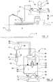
Figure 1 is schematic illustration showing a floating vessel with a lifting arrangement from which a load is suspended and which is operable by a heave compensating system in accordance with the present disclosure; -
Figure 2 is a schematic illustration of a heave compensating system according the a preferred embodiment, and which shows the principal hydraulic and control circuits of the system; -
Figure 3 is an illustration corresponding generally to that offigure 2 , but which depicts the system at an instant in which the load is being lifted in response the vessel falling in a wave trough; -
Figure 4 is a similar illustration depicting the system at an instant in which the load is being paid out from the vessel in response to the vessel rising on the crest of a wave; -
Figure 5 depicts the system in an active heave-compensating mode of operation; -
Figure 6 depicts the system in an alternative passive heave-compensating mode of operation; and -
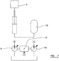
Figure 7 depicts the system in an alternative back-up mode of operation Referring initially tofigure 1 , there is illustrated afloating vessel 1 having acrane 2. Thecrane 2 is shown suspending aload 3 from the vessel into thesea 4. Theload 3 is lifted and lowered via operation of ahydraulic actuator 5. Thevessel 1 is equipped with a hydraulic heave compensating system, indicated generally at 6, which will be described in detail below and which is configured to maintain a substantially constant support force on theload 3 and to maintain the load in a substantially constant position relative to theseabed 7 despite heavingmovement 8 of the vessel in the seaway. The heave compensating system operates to control theactuator 5, and so theactuator 5 can be considered to represent a compensating actuator when operating in this mode. - Although the
vessel 1 is shown infigure 1 in a configuration for lifting and lowering aload 3 via acrane 2, it is to be appreciated that theheave compensating system 6 of the present disclosure is also suitable for use in maintaining drilling or coring tools, or indeed any other equipment suspended from thevessel 1 in a substantially constant position relative to theseabed 7 and under substantially constant load as the vessel moves in heave. - The
heave compensating system 6 comprises a firsthydraulic machine 9 and a secondhydraulic machine 10, both of which are designed to operate as rotary pumps/motors. In preferred arrangements the twohydraulic machines - As illustrated most clearly in
figure 2 , the firsthydraulic machine 9 has adrive shaft 11 which is directly connected to the axle of anelectric motor 12 located between the twohydraulic machines drive shaft 13 which is directly connected to the opposite end of the motor's axle. The twohydraulic machines motor 12, for co-rotation about a common axis. In alternative embodiments, it is envisaged that the twohydraulic machines intermediate motor 12 will all be mounted about a single, shared, drive shaft. - Both
hydraulic machines reservoir 14 for hydraulic fluid. Themotor 24 may preferably be an asynchronous motor, although it is envisaged that variable speed motors could be used in alternative embodiments. - The
actuator 5, as is shown more clearly infigure 2 , takes the form of a hydraulic ram comprising a slideablymoveable piston 15 mounted within acylinder 16. Movement of thepiston 15 within thecylinder 16 is effective to lift or lower theload 3. Thepressure side 17 of theactuator 5 is fluidly connected to the firsthydraulic machine 9 via anactuator fluid line 18. As will be appreciated, movement of the firsthydraulic machine 9 is thus effective to move thepiston 15 of the actuator within thecylinder 16, and hence move theload 3 relative to the vessel. For example, operation of the firsthydraulic machine 9 to pump hydraulic fluid via theactuator line 18 to theactuator 5 is effective to lift theload 3. - The second hydraulic 10 is fluidly connected to a
hydraulic actuator 19 via anaccumulator fluid line 20. Thehydraulic accumulator 19 can take any convenient known form such as, for example; a piston type, a spring type, or a weight loaded type. However, it is preferred to use an accumulator of the known bladder type, in which thebladder 21 contains Nitrogen gas. - A valve 22 is provided in a
bypass fluid line 23 extending between theactuator line 18 and theaccumulator line 20. The valve 22 is operable to move from a first, closed, position as illustrated infigure 2 to a second, open, position effective to connect theaccumulator 19 and theactuator 6 directly along thefluid line 23. - A
controller 24 receives, viasensor cables 25, signals representative of; the position of theload 3 relative to the vessel from aposition sensor 26; the accumulator pressure frompressure sensors sensors hydraulic machines motor 12 viacontrol cables 29, in response to said signals so as to maintain the position of, or load on, theload 3 substantially constant as the vessel moves in heave. - Turning now to consider
figure 3 , a simplified illustration depicts of the heave compensating system in an instant condition corresponding to downwards heave movement of the vessel, for example as the vessel falls in a wave trough. As thevessel 1 falls in this manner, then to maintain theload 3 in a substantially constant position relative to theseabed 7, the load must be lifted, thereby reducing its distance below thevessel 1. Thecontroller 24 operates to detect this heave movement of the vessel and responds by driving the firsthydraulic machine 9 in the manner of a pump, to pump hydraulic fluid into the compensatingactuator 5, thereby lifting theload 3 to compensate for the downwards motion of the vessel. The first machine is driven in this manner by thesecond machine 10, thesecond machine 10 operating in the manner of a motor under the control of thecontroller 24, to provide torque to theinterconnected drive shafts accumulator 19.Arrow 29 thus denotes the flow of energy during this drive phase of the system. -
Figure 4 depicts the heave compensating system at an instant condition corresponding to upwards heave movement of thevessel 1, for example as the vessel rises on a wave crest. As thevessel 1 rises in this manner, then to maintain theload 3 in a substantially constant position relative to theseabed 7, the load must be lowered, thereby increasing its distance below the vessel. The controller operates to detect this upwards heave movement of the vessel and responds by actuating the firsthydraulic machine 9 in the manner of a motor, driven by the hydraulic pressure applied by the compensatingactuator 5. This movement of the firsthydraulic machine 9 drives theinterconnected shafts hydraulic machine 10 in the manner of a pump, increasing the pressure in theaccumulator 19.Arrow 30 thus denotes the reversed flow of energy during this drive phase of the system. - As will be appreciated, the vessel's heave movement in a seaway will tend to alternate continuously between upwards and downwards movement. The
controller 24 thus operates to continuously adjust the position of the compensatingactuator 5, alternating between the two drive phases explained above, as required to maintain the load in a substantially constant position relative to theseabed 7. This continuous operation is denoted infigure 5 , wherearrow 31 denotes the alternating flow of energy between theactuator 5 and theaccumulator 19. - However, during operation in this manner, the energy content of the accumulator will gradually decrease over time due to losses caused by friction and damping in the mechanical structure and due to losses in the
hydraulic machines electric motor 12 is therefore operable, under the control of thecontroller 24, to compensate for these losses by adding torque to theshafts accumulator 19 substantially constant. Thecontroller 24 thus continuously monitors the signals from thesensor 25 which are indicative of the pressure within the accumulator over time, and selectively energises the motor 12 (as depicted byarrow 32 infigure 5 ), during either a lifting or a lowering phase, to add energy back into the hydraulic system in the form of torque to theshafts hydraulic machines controller 24 will be configured to control themotor 12 at least partly in accordance with signals and data representative of previous cycles of vessel heave movement, or even in accordance with calculated data representative of predicted levels of energy recuperated from future heave cycles. - Whilst the
heave compensating system 6 of the present disclosure has been described above with reference to a normal active/passive mode of operation, the system is sufficiently flexible to permit alternative modes of operation should conditions dictate that the normal mode is not possible. For example,figure 6 denotes the system in operation without the supply of energy to theelectric motor 12, such as might be the case, for example, in the event of a power failure or outage onboard thevessel 1. In this situation, it is to be appreciated that thecontroller 24 and its associated circuitry will switch to be powered by an emergency generator or battery or the like, and so will remain operational. As will be appreciated, loss of electrical power to themotor 12 in these circumstances will preclude operation of the motor in the manner described above. In these circumstances, the heave compensating system will thus revert to a purely passive mode of operation as described above, with energy flowing to and fro between theactuator 5 and theaccumulator 19 without any contribution of additional torque from themotor 12. However, it will be appreciated that rotation of theshafts hydraulic machines motor 12 to rotate. The inertia of the inoperative motor in this mode of operation acts to stabilise the rotational speed of theshafts accumulator 19 due to losses in the system no longer being compensated by themotor 12. Thecontroller 24 will continue to monitor the pressure of the accumulator, via thepressure sensor 25 during operation in this passive mode. - In the event that power is not timely restored to the
electric motor 12 to permit reversion to the normal passive/active mode of operation, the pressure within theaccumulator 19 will fall to a level at which the system cannot continue to operate satisfactorily. Thecontroller 24 is thus configured to switch the system to a back-up mode of operation in such circumstances upon detection of the pressure in theaccumulator 19 falling below a predetermined threshold limit as stored in an internal memory in the controller. In this situation, the controller operates to switch the valve 22 from its closed position illustrated infigure 2 to an open position effective to open thebypass flow line 23 between theaccumulator 19 and theactuator 5, thereby directly connecting the accumulator to theactuator 5 and bypassing thehydraulic machines figure 7 . This helps to prevent the further loss of energy from the accumulator as a result of losses in the machines, and so a limited heave compensating function can be retained, albeit with larger force variations than would be the case in either the normal passive/active mode or the passive mode described above. - It is to be appreciated that the equipment of the embodiment described above, and in particular the hydraulic equipment represented by the
actuator 5, the twohydraulic machines accumulator 19 and themotor 12 can be used as a hydraulic power unit for general lifting and lowering operations of thecrane 2. For example, in order to lower the load (or a drilling or coring tool) 3 from the vessel into the sea, thecontroller 24 system can be operated, under the control of thecontroller 24, in a non-compensating lowering mode in which the first hydraulic machine is operated in the manner of a motor, driven by the hydraulic pressure applied by the compensatingactuator 5 generally as depicted infigure 4 . When the load or tool has been lowered to the desired operational depth, it can then be maintained in that position by switching the system to its passive/active heave-compensating mode. When theload 3 or tool is subsequently to be lifted to the surface, the system can be switched out of the compensating mode and into a lifting mode, whereby the firsthydraulic machine 9 is driven in the manner of a pump by the second hydraulic machine to lift the load generally as depicted infigure 3 . Theheave compensating system 6 of the present disclosure can thus be conveniently combined with a hydraulic lifting arrangement aboard thevessel 1. - Whilst the disclosure has been described above in detail with reference to particular embodiments, it is to be appreciated that various modifications or alterations may be made to the system without departing from the scope of the present invention as defined in the appended claims. For example, although the embodiments described above are configured such that the two hydraulic machines and the electric motor are interconnected in a direct 1:1 ratio, it is envisaged that other embodiments could be configured with a different interconnecting ratio.
- It is also envisaged that the machines and the motor could be interconnected via a variable ratio gear arrangement.
- When used in this specification and claims, the terms "comprises" and "comprising" and variations thereof mean that the specified features, steps or integers are included. The terms are not to be interpreted to exclude the presence of other features, steps or integers.
- While the disclosure has been described in conjunction with the exemplary embodiments described above, many equivalent modifications and variations will be apparent to those skilled in the art when given this disclosure. Accordingly, the exemplary embodiments set forth above are considered to be illustrative and not limiting. Various changes to the described embodiments may be made without departing from the scope of the invention as defined in the appended claims.
Claims (15)
- A heave compensating system for a marine vessel, the system comprising:a hydraulic actuator (16) arranged for connection between the vessel and a load to be suspended from the vessel (3), the actuator (16) being hydraulically actuable to vary the distance between the load and the vessel in response to heaving motion of the vessel;the hydraulic actuator (16) being fluidly connected to a first hydraulic machine (9) for actuation by the first hydraulic machine (9);the system further comprising a second hydraulic machine (10) in fluid connection with a hydraulic accumulator (19);an electric motor; anda controller (24) arranged to control hydraulic movement of the first (9) and second (10) hydraulic machines and power to said electric motor (12) in response to one or more signals representative of a wave-induced heave movement of the vessel and/or a wave induced force applied to the load (3);characterised bythe first (9) and second (10) hydraulic machines being mechanically connected to one another and also both being mechanically connected to said electric motor (12); wherein the first (9) and second (10) hydraulic machines are arranged to alternate between operating in a first drive phase and a second drive phase as the wave-induced heave movement of the vessel and/or the wave induced force applied to the load (3) alternates between an upwards movement and a downwards movement, wherein:in the first drive phase, the first hydraulic machine (9) operates as a pump and the second hydraulic machine (10) operates as a motor, andin the second drive phase, the first hydraulic machine (9) operates as a motor and the second hydraulic machine (10) operates as a pump.
- A system according to claim 1, wherein the two hydraulic machines (9, 10) and the electric motor are interconnected via a direct 1:1 ratio.
- A system according to claim 1 or claim 2, wherein the two hydraulic machines (9, 10) and the electric motor (12) are all mounted about a common drive shaft.
- A system according to claim 1 or claim 2, wherein each said hydraulic machine has a respective drive shaft (11, 13), the two shafts being substantially co-axial and interconnected via said motor, the motor being arranged between said drive shafts for rotation about the axis of said shafts.
- A system according to any preceding claim, wherein the electric motor is an asynchronous motor.
- A system according to any preceding claim, further comprising a valve (22) arranged in a fluid line between the accumulator (19) and the actuator (5), the valve being operable to move between a first position in which the accumulator and the actuator are fluidly isolated from one another, and a second position in which the accumulator and the actuator are fluidly connected via the fluid line.
- A system according to claim 6, wherein the controller (24) is arranged to control operation of the valve (22) in dependence on a signal representative of the hydraulic pressure in the accumulator, the controller being configured to move the valve from the first position to the second position in response to the pressure falling to a predetermined threshold value.
- A system according to any preceding claim, wherein the controller (24) is arranged to receive a signal representative of the hydraulic pressure in the accumulator, and to control power to the electric motor in response thereto.
- A system according to any preceding claim, wherein the controller (24) is arranged to receive a signal representative of the position of the load relative to the vessel and to control movement of the first and second hydraulic machines in response thereto.
- A system according to any preceding claim, operable to maintain a substantially constant support force on the load suspended from the vessel (1) during heaving movement of the vessel.
- A system according to any one of claims 1 to 9, operable to maintain the load (3) suspended from the vessel in a substantially constant position during heaving movement of the vessel.
- A method of operating a heave compensating system according to any preceding claim in an active mode in which the controller (24) actively controls energisation of the electric motor (12).
- A method according to claim 12, wherein power to the electric motor is controlled in dependence on the hydraulic pressure in the accumulator in said active mode.
- A method of operating a heave compensating system according to any one of claims 1 to 11, in a passive mode in which the motor is not energized.
- A method of operating a heave compensating system according to claim 6 or claim 7, wherein the valve is moved from its first position to its second position to fluidly interconnect the actuator and the accumulator, thereby bypassing the first and second hydraulic machines, in response to the pressure within the accumulator falling below a predetermined threshold value.
Applications Claiming Priority (2)
| Application Number | Priority Date | Filing Date | Title |
|---|---|---|---|
| GB1019555.0A GB2485570A (en) | 2010-11-18 | 2010-11-18 | Heave compensating system |
| PCT/GB2011/001467 WO2012066268A2 (en) | 2010-11-18 | 2011-10-11 | A heave compensating system |
Publications (2)
| Publication Number | Publication Date |
|---|---|
| EP2640657A2 EP2640657A2 (en) | 2013-09-25 |
| EP2640657B1 true EP2640657B1 (en) | 2018-11-21 |
Family
ID=43431660
Family Applications (1)
| Application Number | Title | Priority Date | Filing Date |
|---|---|---|---|
| EP11773512.6A Active EP2640657B1 (en) | 2010-11-18 | 2011-10-11 | A heave compensating system |
Country Status (7)
| Country | Link |
|---|---|
| US (1) | US9267340B2 (en) |
| EP (1) | EP2640657B1 (en) |
| KR (1) | KR101839985B1 (en) |
| BR (1) | BR112013011835B8 (en) |
| GB (1) | GB2485570A (en) |
| RU (1) | RU2569511C2 (en) |
| WO (1) | WO2012066268A2 (en) |
Families Citing this family (15)
| Publication number | Priority date | Publication date | Assignee | Title |
|---|---|---|---|---|
| JP6133844B2 (en) * | 2011-03-28 | 2017-05-24 | オーシャン パワー テクノロジーズ,インク. | Wave energy converter with rotary fluid spring |
| DE102012017004A1 (en) | 2012-08-28 | 2014-03-06 | Hydac Technology Gmbh | Hydraulic energy recovery system |
| KR101462582B1 (en) * | 2013-01-09 | 2014-11-17 | 주식회사 칸 | Heave compensator control system for a marine structure |
| KR101587478B1 (en) | 2014-07-14 | 2016-01-22 | 대우조선해양 주식회사 | Heave motion damping device for marine floating body |
| GB201419394D0 (en) | 2014-10-31 | 2014-12-17 | Saipem Spa | Offshore lifting of a load with heave compensation |
| US10359063B2 (en) | 2014-11-24 | 2019-07-23 | Xuzhou Heavy Machinery Co.., Ltd. | Method and system for recovering and utilizing operating energy of crane, and crane |
| DE102015222910A1 (en) * | 2014-11-27 | 2016-06-02 | Robert Bosch Gmbh | Motion compensation device |
| NL2014318B1 (en) * | 2015-02-20 | 2016-10-13 | Boskalis Bv Baggermaatschappij | Vessel with heave compensation system. |
| EP3144543A1 (en) * | 2015-09-17 | 2017-03-22 | Robert Bosch Gmbh | Device and method for controlling a safety valve arrangement |
| CA3013291A1 (en) | 2016-02-22 | 2017-08-31 | Safelink As | Mobile active heave compensator |
| DE102016005477A1 (en) * | 2016-05-03 | 2017-11-09 | Hycom B.V. | Compensation device for maintaining predetermined target positions of a manageable load |
| CN106364630B (en) * | 2016-09-22 | 2018-07-24 | 华中科技大学 | One kind having half Active Heave Compensation System of cable underwater robot |
| EP3301062B1 (en) | 2016-10-03 | 2021-11-03 | National Oilwell Varco Norway AS | System arranged on a marine vessel or platform, such as for providing heave compensation and hoisting |
| EP4080062A1 (en) * | 2021-04-23 | 2022-10-26 | Norrhydro OY | Electrohydraulic actuator and method |
| CN113738714A (en) * | 2021-08-04 | 2021-12-03 | 温州大学 | Deep sea robot cable system heave compensation device |
Family Cites Families (12)
| Publication number | Priority date | Publication date | Assignee | Title |
|---|---|---|---|---|
| US3653636A (en) * | 1970-02-09 | 1972-04-04 | Exxon Production Research Co | Wave motion compensation system for suspending well equipment from a floating vessel |
| US3905580A (en) * | 1973-10-09 | 1975-09-16 | Global Marine Inc | Heave compensator |
| US4176722A (en) * | 1978-03-15 | 1979-12-04 | Global Marine, Inc. | Marine riser system with dual purpose lift and heave compensator mechanism |
| GB2055342B (en) * | 1979-07-27 | 1983-10-26 | Vickers Offshore Projects & De | Maintaining constant tension |
| FR2597081B1 (en) * | 1986-04-10 | 1988-06-10 | Alsthom | DEVICE FOR TENSIONING A TENSION CABLE LINKED TO ONE OF ITS ENDS AT THE UPPER END OF A TUBE WHOSE LOWER END IS ATTACHED TO THE BOTTOM OF THE SEA |
| US5209302A (en) * | 1991-10-04 | 1993-05-11 | Retsco, Inc. | Semi-active heave compensation system for marine vessels |
| US6378301B2 (en) * | 1996-09-25 | 2002-04-30 | Komatsu Ltd. | Pressurized fluid recovery/reutilization system |
| RU2262464C2 (en) * | 2003-06-25 | 2005-10-20 | Закрытое акционерное общество "Центральный Научно-исследовательский Институт Судового Машиностроения" (ЗАО "ЦНИИ СМ") | Shipboard crane hydraulic system |
| NO322172B1 (en) | 2004-05-21 | 2006-08-21 | Fmc Kongsberg Subsea As | Apparatus in connection with HIV compensation of a pressurized riser between a subsea installation and a floating unit. |
| CN100427771C (en) * | 2006-12-14 | 2008-10-22 | 浙江大学 | Energy saving hydraulic lifting system of variable hydraulic counterweight |
| NO336258B1 (en) * | 2007-09-19 | 2015-07-06 | Nat Oilwell Varco Norway As | Method and device for lift compensation. |
| DE602008004099D1 (en) * | 2008-04-29 | 2011-02-03 | Parker Hannifin Ab | Arrangement for operating a hydraulic device |
-
2010
- 2010-11-18 GB GB1019555.0A patent/GB2485570A/en not_active Withdrawn
-
2011
- 2011-10-11 WO PCT/GB2011/001467 patent/WO2012066268A2/en active Application Filing
- 2011-10-11 EP EP11773512.6A patent/EP2640657B1/en active Active
- 2011-10-11 RU RU2013122781/11A patent/RU2569511C2/en active
- 2011-10-11 BR BR112013011835A patent/BR112013011835B8/en active IP Right Grant
- 2011-10-11 US US13/988,281 patent/US9267340B2/en active Active
- 2011-10-11 KR KR1020137015123A patent/KR101839985B1/en active IP Right Grant
Non-Patent Citations (1)
| Title |
|---|
| None * |
Also Published As
| Publication number | Publication date |
|---|---|
| US9267340B2 (en) | 2016-02-23 |
| BR112013011835A2 (en) | 2016-08-16 |
| KR20130113482A (en) | 2013-10-15 |
| RU2013122781A (en) | 2014-12-27 |
| WO2012066268A2 (en) | 2012-05-24 |
| WO2012066268A3 (en) | 2013-05-16 |
| KR101839985B1 (en) | 2018-03-20 |
| EP2640657A2 (en) | 2013-09-25 |
| GB201019555D0 (en) | 2010-12-29 |
| BR112013011835B8 (en) | 2022-05-10 |
| BR112013011835B1 (en) | 2021-01-26 |
| GB2485570A (en) | 2012-05-23 |
| US20130312979A1 (en) | 2013-11-28 |
| RU2569511C2 (en) | 2015-11-27 |
Similar Documents
| Publication | Publication Date | Title |
|---|---|---|
| EP2640657B1 (en) | A heave compensating system | |
| US4962817A (en) | Active reference system | |
| US10081988B2 (en) | Heave compensation winches | |
| US5894895A (en) | Heave compensator for drill ships | |
| AU2017271305B2 (en) | Transportable inline heave compensator | |
| US10689922B2 (en) | System and method for providing tension or heave compensation in an offshore drilling environment | |
| US8297597B2 (en) | Method for lift compensation | |
| EP3155206B1 (en) | Winches and hoisting systems with heave compensation | |
| CN109422204B (en) | Laying and recycling system for offshore operation | |
| CA2462071C (en) | Multi-purpose coiled tubing handling system | |
| US20190077641A1 (en) | Winch system | |
| US3905580A (en) | Heave compensator | |
| EP3287589A1 (en) | An offshore floating vessel and a method of operating the same | |
| WO2011145947A1 (en) | An apparatus and method for recuperation of hydraulic energy | |
| US11059547B2 (en) | System arranged on a marine vessel or platform, such as for providing heave compensation and hoisting | |
| EP3059199B1 (en) | Vessel with heave compensation system | |
| EP3227520B1 (en) | Heave compensation method | |
| NO342595B1 (en) | Rotary inline heave compensator | |
| EP3882123A1 (en) | A method of harvesting energy from a lifting structure | |
| GB2571267A (en) | Offshore energy management system | |
| KR20180036204A (en) | Rotary hydraulic winch type heave motion compensation system |
Legal Events
| Date | Code | Title | Description |
|---|---|---|---|
| PUAI | Public reference made under article 153(3) epc to a published international application that has entered the european phase |
Free format text: ORIGINAL CODE: 0009012 |
|
| 17P | Request for examination filed |
Effective date: 20130429 |
|
| AK | Designated contracting states |
Kind code of ref document: A2 Designated state(s): AL AT BE BG CH CY CZ DE DK EE ES FI FR GB GR HR HU IE IS IT LI LT LU LV MC MK MT NL NO PL PT RO RS SE SI SK SM TR |
|
| DAX | Request for extension of the european patent (deleted) | ||
| STAA | Information on the status of an ep patent application or granted ep patent |
Free format text: STATUS: EXAMINATION IS IN PROGRESS |
|
| 17Q | First examination report despatched |
Effective date: 20170215 |
|
| GRAP | Despatch of communication of intention to grant a patent |
Free format text: ORIGINAL CODE: EPIDOSNIGR1 |
|
| STAA | Information on the status of an ep patent application or granted ep patent |
Free format text: STATUS: GRANT OF PATENT IS INTENDED |
|
| INTG | Intention to grant announced |
Effective date: 20180514 |
|
| GRAS | Grant fee paid |
Free format text: ORIGINAL CODE: EPIDOSNIGR3 |
|
| GRAA | (expected) grant |
Free format text: ORIGINAL CODE: 0009210 |
|
| STAA | Information on the status of an ep patent application or granted ep patent |
Free format text: STATUS: THE PATENT HAS BEEN GRANTED |
|
| AK | Designated contracting states |
Kind code of ref document: B1 Designated state(s): AL AT BE BG CH CY CZ DE DK EE ES FI FR GB GR HR HU IE IS IT LI LT LU LV MC MK MT NL NO PL PT RO RS SE SI SK SM TR |
|
| REG | Reference to a national code |
Ref country code: CH Ref legal event code: EP |
|
| REG | Reference to a national code |
Ref country code: IE Ref legal event code: FG4D |
|
| REG | Reference to a national code |
Ref country code: DE Ref legal event code: R096 Ref document number: 602011054105 Country of ref document: DE |
|
| REG | Reference to a national code |
Ref country code: AT Ref legal event code: REF Ref document number: 1067288 Country of ref document: AT Kind code of ref document: T Effective date: 20181215 |
|
| REG | Reference to a national code |
Ref country code: NL Ref legal event code: MP Effective date: 20181121 |
|
| REG | Reference to a national code |
Ref country code: AT Ref legal event code: MK05 Ref document number: 1067288 Country of ref document: AT Kind code of ref document: T Effective date: 20181121 Ref country code: NO Ref legal event code: T2 Effective date: 20181121 |
|
| PG25 | Lapsed in a contracting state [announced via postgrant information from national office to epo] |
Ref country code: IS Free format text: LAPSE BECAUSE OF FAILURE TO SUBMIT A TRANSLATION OF THE DESCRIPTION OR TO PAY THE FEE WITHIN THE PRESCRIBED TIME-LIMIT Effective date: 20190321 Ref country code: ES Free format text: LAPSE BECAUSE OF FAILURE TO SUBMIT A TRANSLATION OF THE DESCRIPTION OR TO PAY THE FEE WITHIN THE PRESCRIBED TIME-LIMIT Effective date: 20181121 Ref country code: AT Free format text: LAPSE BECAUSE OF FAILURE TO SUBMIT A TRANSLATION OF THE DESCRIPTION OR TO PAY THE FEE WITHIN THE PRESCRIBED TIME-LIMIT Effective date: 20181121 Ref country code: LT Free format text: LAPSE BECAUSE OF FAILURE TO SUBMIT A TRANSLATION OF THE DESCRIPTION OR TO PAY THE FEE WITHIN THE PRESCRIBED TIME-LIMIT Effective date: 20181121 Ref country code: HR Free format text: LAPSE BECAUSE OF FAILURE TO SUBMIT A TRANSLATION OF THE DESCRIPTION OR TO PAY THE FEE WITHIN THE PRESCRIBED TIME-LIMIT Effective date: 20181121 Ref country code: BG Free format text: LAPSE BECAUSE OF FAILURE TO SUBMIT A TRANSLATION OF THE DESCRIPTION OR TO PAY THE FEE WITHIN THE PRESCRIBED TIME-LIMIT Effective date: 20190221 Ref country code: FI Free format text: LAPSE BECAUSE OF FAILURE TO SUBMIT A TRANSLATION OF THE DESCRIPTION OR TO PAY THE FEE WITHIN THE PRESCRIBED TIME-LIMIT Effective date: 20181121 Ref country code: LV Free format text: LAPSE BECAUSE OF FAILURE TO SUBMIT A TRANSLATION OF THE DESCRIPTION OR TO PAY THE FEE WITHIN THE PRESCRIBED TIME-LIMIT Effective date: 20181121 |
|
| PG25 | Lapsed in a contracting state [announced via postgrant information from national office to epo] |
Ref country code: RS Free format text: LAPSE BECAUSE OF FAILURE TO SUBMIT A TRANSLATION OF THE DESCRIPTION OR TO PAY THE FEE WITHIN THE PRESCRIBED TIME-LIMIT Effective date: 20181121 Ref country code: SE Free format text: LAPSE BECAUSE OF FAILURE TO SUBMIT A TRANSLATION OF THE DESCRIPTION OR TO PAY THE FEE WITHIN THE PRESCRIBED TIME-LIMIT Effective date: 20181121 Ref country code: AL Free format text: LAPSE BECAUSE OF FAILURE TO SUBMIT A TRANSLATION OF THE DESCRIPTION OR TO PAY THE FEE WITHIN THE PRESCRIBED TIME-LIMIT Effective date: 20181121 Ref country code: PT Free format text: LAPSE BECAUSE OF FAILURE TO SUBMIT A TRANSLATION OF THE DESCRIPTION OR TO PAY THE FEE WITHIN THE PRESCRIBED TIME-LIMIT Effective date: 20190321 Ref country code: NL Free format text: LAPSE BECAUSE OF FAILURE TO SUBMIT A TRANSLATION OF THE DESCRIPTION OR TO PAY THE FEE WITHIN THE PRESCRIBED TIME-LIMIT Effective date: 20181121 Ref country code: GR Free format text: LAPSE BECAUSE OF FAILURE TO SUBMIT A TRANSLATION OF THE DESCRIPTION OR TO PAY THE FEE WITHIN THE PRESCRIBED TIME-LIMIT Effective date: 20190222 |
|
| PG25 | Lapsed in a contracting state [announced via postgrant information from national office to epo] |
Ref country code: PL Free format text: LAPSE BECAUSE OF FAILURE TO SUBMIT A TRANSLATION OF THE DESCRIPTION OR TO PAY THE FEE WITHIN THE PRESCRIBED TIME-LIMIT Effective date: 20181121 Ref country code: DK Free format text: LAPSE BECAUSE OF FAILURE TO SUBMIT A TRANSLATION OF THE DESCRIPTION OR TO PAY THE FEE WITHIN THE PRESCRIBED TIME-LIMIT Effective date: 20181121 Ref country code: IT Free format text: LAPSE BECAUSE OF FAILURE TO SUBMIT A TRANSLATION OF THE DESCRIPTION OR TO PAY THE FEE WITHIN THE PRESCRIBED TIME-LIMIT Effective date: 20181121 Ref country code: CZ Free format text: LAPSE BECAUSE OF FAILURE TO SUBMIT A TRANSLATION OF THE DESCRIPTION OR TO PAY THE FEE WITHIN THE PRESCRIBED TIME-LIMIT Effective date: 20181121 |
|
| REG | Reference to a national code |
Ref country code: DE Ref legal event code: R097 Ref document number: 602011054105 Country of ref document: DE |
|
| PG25 | Lapsed in a contracting state [announced via postgrant information from national office to epo] |
Ref country code: SM Free format text: LAPSE BECAUSE OF FAILURE TO SUBMIT A TRANSLATION OF THE DESCRIPTION OR TO PAY THE FEE WITHIN THE PRESCRIBED TIME-LIMIT Effective date: 20181121 Ref country code: EE Free format text: LAPSE BECAUSE OF FAILURE TO SUBMIT A TRANSLATION OF THE DESCRIPTION OR TO PAY THE FEE WITHIN THE PRESCRIBED TIME-LIMIT Effective date: 20181121 Ref country code: RO Free format text: LAPSE BECAUSE OF FAILURE TO SUBMIT A TRANSLATION OF THE DESCRIPTION OR TO PAY THE FEE WITHIN THE PRESCRIBED TIME-LIMIT Effective date: 20181121 Ref country code: SK Free format text: LAPSE BECAUSE OF FAILURE TO SUBMIT A TRANSLATION OF THE DESCRIPTION OR TO PAY THE FEE WITHIN THE PRESCRIBED TIME-LIMIT Effective date: 20181121 |
|
| PLBE | No opposition filed within time limit |
Free format text: ORIGINAL CODE: 0009261 |
|
| STAA | Information on the status of an ep patent application or granted ep patent |
Free format text: STATUS: NO OPPOSITION FILED WITHIN TIME LIMIT |
|
| 26N | No opposition filed |
Effective date: 20190822 |
|
| PG25 | Lapsed in a contracting state [announced via postgrant information from national office to epo] |
Ref country code: SI Free format text: LAPSE BECAUSE OF FAILURE TO SUBMIT A TRANSLATION OF THE DESCRIPTION OR TO PAY THE FEE WITHIN THE PRESCRIBED TIME-LIMIT Effective date: 20181121 |
|
| PG25 | Lapsed in a contracting state [announced via postgrant information from national office to epo] |
Ref country code: TR Free format text: LAPSE BECAUSE OF FAILURE TO SUBMIT A TRANSLATION OF THE DESCRIPTION OR TO PAY THE FEE WITHIN THE PRESCRIBED TIME-LIMIT Effective date: 20181121 |
|
| REG | Reference to a national code |
Ref country code: DE Ref legal event code: R119 Ref document number: 602011054105 Country of ref document: DE |
|
| PG25 | Lapsed in a contracting state [announced via postgrant information from national office to epo] |
Ref country code: MC Free format text: LAPSE BECAUSE OF FAILURE TO SUBMIT A TRANSLATION OF THE DESCRIPTION OR TO PAY THE FEE WITHIN THE PRESCRIBED TIME-LIMIT Effective date: 20181121 |
|
| REG | Reference to a national code |
Ref country code: CH Ref legal event code: PL |
|
| PG25 | Lapsed in a contracting state [announced via postgrant information from national office to epo] |
Ref country code: LI Free format text: LAPSE BECAUSE OF NON-PAYMENT OF DUE FEES Effective date: 20191031 Ref country code: LU Free format text: LAPSE BECAUSE OF NON-PAYMENT OF DUE FEES Effective date: 20191011 Ref country code: DE Free format text: LAPSE BECAUSE OF NON-PAYMENT OF DUE FEES Effective date: 20200501 Ref country code: CH Free format text: LAPSE BECAUSE OF NON-PAYMENT OF DUE FEES Effective date: 20191031 |
|
| REG | Reference to a national code |
Ref country code: BE Ref legal event code: MM Effective date: 20191031 |
|
| PG25 | Lapsed in a contracting state [announced via postgrant information from national office to epo] |
Ref country code: BE Free format text: LAPSE BECAUSE OF NON-PAYMENT OF DUE FEES Effective date: 20191031 |
|
| PG25 | Lapsed in a contracting state [announced via postgrant information from national office to epo] |
Ref country code: IE Free format text: LAPSE BECAUSE OF NON-PAYMENT OF DUE FEES Effective date: 20191011 Ref country code: FR Free format text: LAPSE BECAUSE OF NON-PAYMENT OF DUE FEES Effective date: 20191031 |
|
| PG25 | Lapsed in a contracting state [announced via postgrant information from national office to epo] |
Ref country code: CY Free format text: LAPSE BECAUSE OF FAILURE TO SUBMIT A TRANSLATION OF THE DESCRIPTION OR TO PAY THE FEE WITHIN THE PRESCRIBED TIME-LIMIT Effective date: 20181121 |
|
| PG25 | Lapsed in a contracting state [announced via postgrant information from national office to epo] |
Ref country code: MT Free format text: LAPSE BECAUSE OF FAILURE TO SUBMIT A TRANSLATION OF THE DESCRIPTION OR TO PAY THE FEE WITHIN THE PRESCRIBED TIME-LIMIT Effective date: 20181121 Ref country code: HU Free format text: LAPSE BECAUSE OF FAILURE TO SUBMIT A TRANSLATION OF THE DESCRIPTION OR TO PAY THE FEE WITHIN THE PRESCRIBED TIME-LIMIT; INVALID AB INITIO Effective date: 20111011 |
|
| PG25 | Lapsed in a contracting state [announced via postgrant information from national office to epo] |
Ref country code: MK Free format text: LAPSE BECAUSE OF FAILURE TO SUBMIT A TRANSLATION OF THE DESCRIPTION OR TO PAY THE FEE WITHIN THE PRESCRIBED TIME-LIMIT Effective date: 20181121 |
|
| PGFP | Annual fee paid to national office [announced via postgrant information from national office to epo] |
Ref country code: GB Payment date: 20230831 Year of fee payment: 13 |
|
| PGFP | Annual fee paid to national office [announced via postgrant information from national office to epo] |
Ref country code: NO Payment date: 20231010 Year of fee payment: 13 |