EP2640448B1 - Dispositif de distribution de médicament - Google Patents
Dispositif de distribution de médicament Download PDFInfo
- Publication number
- EP2640448B1 EP2640448B1 EP11841646.0A EP11841646A EP2640448B1 EP 2640448 B1 EP2640448 B1 EP 2640448B1 EP 11841646 A EP11841646 A EP 11841646A EP 2640448 B1 EP2640448 B1 EP 2640448B1
- Authority
- EP
- European Patent Office
- Prior art keywords
- guard
- medicament
- medicament delivery
- delivery device
- container holder
- Prior art date
- Legal status (The legal status is an assumption and is not a legal conclusion. Google has not performed a legal analysis and makes no representation as to the accuracy of the status listed.)
- Active
Links
- 239000003814 drug Substances 0.000 title claims description 150
- 230000007246 mechanism Effects 0.000 claims description 17
- 238000002347 injection Methods 0.000 claims description 11
- 239000007924 injection Substances 0.000 claims description 11
- UHZZMRAGKVHANO-UHFFFAOYSA-M chlormequat chloride Chemical group [Cl-].C[N+](C)(C)CCCl UHZZMRAGKVHANO-UHFFFAOYSA-M 0.000 claims description 4
- 230000004913 activation Effects 0.000 claims description 3
- 238000006073 displacement reaction Methods 0.000 claims description 2
- 210000002105 tongue Anatomy 0.000 description 8
- 239000007788 liquid Substances 0.000 description 3
- 208000012266 Needlestick injury Diseases 0.000 description 2
- 230000003213 activating effect Effects 0.000 description 1
- 229940090047 auto-injector Drugs 0.000 description 1
- 230000001419 dependent effect Effects 0.000 description 1
- 239000003085 diluting agent Substances 0.000 description 1
- 238000012377 drug delivery Methods 0.000 description 1
- 230000003993 interaction Effects 0.000 description 1
- 230000035515 penetration Effects 0.000 description 1
- 239000000843 powder Substances 0.000 description 1
Images


Classifications
-
- A—HUMAN NECESSITIES
- A61—MEDICAL OR VETERINARY SCIENCE; HYGIENE
- A61M—DEVICES FOR INTRODUCING MEDIA INTO, OR ONTO, THE BODY; DEVICES FOR TRANSDUCING BODY MEDIA OR FOR TAKING MEDIA FROM THE BODY; DEVICES FOR PRODUCING OR ENDING SLEEP OR STUPOR
- A61M5/00—Devices for bringing media into the body in a subcutaneous, intra-vascular or intramuscular way; Accessories therefor, e.g. filling or cleaning devices, arm-rests
- A61M5/178—Syringes
- A61M5/19—Syringes having more than one chamber, e.g. including a manifold coupling two parallelly aligned syringes through separate channels to a common discharge assembly
-
- A—HUMAN NECESSITIES
- A61—MEDICAL OR VETERINARY SCIENCE; HYGIENE
- A61M—DEVICES FOR INTRODUCING MEDIA INTO, OR ONTO, THE BODY; DEVICES FOR TRANSDUCING BODY MEDIA OR FOR TAKING MEDIA FROM THE BODY; DEVICES FOR PRODUCING OR ENDING SLEEP OR STUPOR
- A61M5/00—Devices for bringing media into the body in a subcutaneous, intra-vascular or intramuscular way; Accessories therefor, e.g. filling or cleaning devices, arm-rests
- A61M5/178—Syringes
- A61M5/31—Details
- A61M5/315—Pistons; Piston-rods; Guiding, blocking or restricting the movement of the rod or piston; Appliances on the rod for facilitating dosing ; Dosing mechanisms
- A61M5/31525—Dosing
-
- A—HUMAN NECESSITIES
- A61—MEDICAL OR VETERINARY SCIENCE; HYGIENE
- A61M—DEVICES FOR INTRODUCING MEDIA INTO, OR ONTO, THE BODY; DEVICES FOR TRANSDUCING BODY MEDIA OR FOR TAKING MEDIA FROM THE BODY; DEVICES FOR PRODUCING OR ENDING SLEEP OR STUPOR
- A61M5/00—Devices for bringing media into the body in a subcutaneous, intra-vascular or intramuscular way; Accessories therefor, e.g. filling or cleaning devices, arm-rests
- A61M5/178—Syringes
- A61M5/31—Details
- A61M5/315—Pistons; Piston-rods; Guiding, blocking or restricting the movement of the rod or piston; Appliances on the rod for facilitating dosing ; Dosing mechanisms
- A61M5/31533—Dosing mechanisms, i.e. setting a dose
- A61M5/31545—Setting modes for dosing
- A61M5/31548—Mechanically operated dose setting member
- A61M5/3155—Mechanically operated dose setting member by rotational movement of dose setting member, e.g. during setting or filling of a syringe
Definitions
- the present invention relates to a medicament delivery device and in particular a medicament delivery device utilizing multi-chamber medicament containers that require mixing before drug delivery to a patient.
- the medicament and the liquid are kept in different compartments in the medicament container and are mixed just before use by moving a dividing wall or stopper such that the compartments can communicate with each other.
- the multi-chamber medicament containers entail more handling steps before a dose of medicament can be injected in that the plunger rod of the injector has to move the stopper or stoppers of the medicament container in order to initiate the mixing.
- Another feature of many medicament delivery devices and in particular injectors is the attachment of a medicament delivery member, in particular an injection needle to a medicament container and then how to avoid unintentional needle sticks.
- Document WO2006/057604 describes an autoinjector having a needle shield that interacts with a cylindrical rotator to release a plunger rod for injection of a liquid medicament.
- the needle shield and the rotator may also initiate a mixing operation, by releasing the spring-biased plunger rod, before injection of a dose of medicament.
- Document WO2010/000559 discloses a medicament delivery device utilizing a multi-chamber medicament container where the mixing is obtained by rotating a medicament container holder, positioned in the proximal housing part, into a distal housing part whereby the stopper of the medicament container is moved against a plunger rod. In the initial position the proximal end of the medicament container is protruding beyond the proximal housing part, where the latter also acts as a needle shield, such that a medicament delivery device can be attached to the medicament container holder. When the mixing has been performed, the medicament delivery member is drawn into the proximal housing/needle shield.
- the needle shield is now used for actuating the device in that when a penetration is performed, the needle shield is pushed in the distal direction, whereby it triggers an auto-injection sequence.
- the needle shield assembly extends almost to the distal end of the device in order to be able to actuate the injection.
- the aim of the present invention is to provide a medicament delivery device that can handle multi-chamber medicament containers in a simple and intuitive but yet safe way.
- a medicament delivery device according to the features of the independent patent claim.
- Preferable embodiments of the invention form the subject of the dependent patent claims.
- a medicament delivery device comprising a body which comprises a housing and a medicament container holder accommodating a multi-chamber medicament container, wherein said housing and said medicament container holder are interactively connected to and movable relative each other; the medicament container holder comprising attachment means for attaching a delivery member; a mixing guard mechanism interactively connected to the body for driving the medicament container holder within the housing and thereby achieving a reconstitution wherein the mixing guard mechanism comprises a mixing cylinder unit and a tubular medicament delivery member guard operably connected to the medicament container holder, such that when the mixing cylinder unit is operated, the medicament container holder is moved in relation to the medicament delivery member guard between a pre-mix position in which said attachment means protrudes through a proximal end of said medicament delivery member guard for allowing the attachment of a delivery member and a mixed position in which said attachment means and said attached delivery member is positioned within the medicament delivery member guard, wherein said mixing guard mechanism further comprises a guard lock and release member operably
- movement in the distal direction of the guard member when the device is pressed against a dose delivery site, causes a turning of a rotator member comprised in said mixing cylinder unit.
- said turning is caused by said rotator member comprising at least one groove inclined in relation to the longitudinal direction of the device, cooperating with at least one protrusion arranged on the guard during distal movement of said guard.
- said mixing guard mechanism further comprises a resilient member operably arranged to said guard for urging said guard in the proximal direction.
- the rotator member comprises a first guard locking means interactively connected to the rotator member such that proximal movement of said guard, after removal from a medicament delivery site, causes a locking of said guard in a proximal position covering said medicament delivery member.
- said mixing guard mechanism comprises first connection means, interactively connecting said housing and said medicament container holder for allowing the medicament container holder to be displaced within the housing.
- said first connection means comprises cooperating threads on said housing and said medicament container holder.
- said first guard locking means comprises at least one proximally directed resilient tongue arranged to said rotator member and at least one protrusion arranged to said guard such that when said guard is proximally displaced, said at least one protrusion passes said at least one tongue, thereby preventing subsequent distal displacement of said guard.
- said medicament container holder and said guard are slidably connected but rotationally locked to each other by second connection means.
- said mixing cylinder is arranged to said guard such that they are slidably connected but rotationally locked to each other by third connection means.
- said mixing cylinder and a connector sleeve are fixedly connected to each other by fourth connection means.
- said connector sleeve and said housing are connected to each other by fifth connection means which prevent a longitudinal movement in relation to each other but allow rotation in relation to each other.
- said rotator member and said connector sleeve are connected to each other by sixth connection means which prevent a longitudinal movement in relation to each other but allow partial rotation in relation to each other, and wherein said connector sleeve and said rotator member are coaxially arranged within said mixing cylinder.
- said rotator member and said mixing cylinder are one-direction-rotatably connected to each other by seventh connection means.
- it further comprises drive means arranged within said housing and adapted to drive a stopper positioned within said multi-chamber container.
- said drive means comprises a plunger rod and a force member operatively acting on said plunger rod for urging it in the proximal direction.
- it further comprises a holding means for holding said drive means in a pre-tensioned state.
- activation means capable of acting on said holding means for releasing the drive means from the pre-tensioned state
- the device is an injection device.
- a tubular medicament delivery member guard operatively connected to the medicament container holder and the mixing means provides the possibility of attaching a medicament delivery member to the device and then during the mixing operation cover the medicament delivery member by activating the tubular guard member.
- a rotator member By using a rotator member, several functions of the device are obtained with few components and provides the interaction of functions.
- the mixing guard mechanism enables a pushing of the tubular guard in the distal direction when the device is pressed against a dose delivery site.
- This movement of the tubular guard causes components of the mixing guard mechanism to be moved and thus prepared for a locking of the tubular guard member when the device is removed from the dose delivery site after completed dose delivery, wherein the tubular guard is pushed in the proximal direction by the spring force, thereby surrounding the medicament delivery member in a locked state, whereby the medicament delivery member cannot be tampered with.
- distal part/end refers to the part/end of the delivery device, or the parts/ends of the members thereof, which is/are located the furthest away from the medicament delivery site.
- proximal part/end refers to the part/end of the delivery device, or the parts/ends of the members thereof, which, is/are located closest to the medicament delivery site.
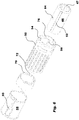
- the medicament delivery device shown in the drawings comprises a body, which in turn comprises a generally elongated housing 10 and a generally tubular medicament container holder 12, Fig. 3 .
- the proximal end of the medicament container holder comprises a neck portion 14 onto which a medicament delivery member 16 may be releasibly attached.
- the interior of the medicament container holder is arranged to house a multi-chamber medicament container 18, having a proximal end fitting into the neck portion 14 of the medicament container holder 12.
- the interior of the medicament container 12 contains a number of movable stoppers 20, 22, which stoppers form a number of chambers 24, 26 containing medicament in powder form and a diluent.
- a drive mechanism is further arranged in the housing, comprising an elongated plunger rod 28 having a proximal end in contact with the stopper 20 at the distal end of the medicament container 12.
- the plunger rod 28 is operatively connected to a drive force member 30 of the drive mechanism operatively acting on the plunger rod 28 for urging it in the proximal direction.
- the device further comprises a holding member 32 capable of holding the drive force member 30 in a pre-tensioned state as well as an actuation member 34 capable of acting on said holding member 32 for releasing the drive force member 30 from the pre-tensioned state, Fig. 2 .
- the actuation member 34 comprises an actuation button 36 extending through a distal end of the housing.
- the device further comprises a mixing guard mechanism arranged for mixing the content of the chambers of the multi-chamber medicament container.
- the first connection means comprises threads 38 on the outer surface of the medicament container holder 12, which threads 38 cooperate with corresponding threads 40, Fig. 2 , on the inner surface of the housing 10.
- the mixing means further comprises longitudinally extending grooves 42, Fig. 3 , on the outer surface of the medicament container holder 12, which grooves 42 cooperate with corresponding ribs 44, Fig. 5 , on an inner surface of a generally tubular medicament delivery member guard 46, forming second connection means.
- a guard member lock and release member is arranged wherein the outer surface of the medicament container holder 12 at its proximal end is arranged with two oppositely positioned outwardly directed protrusions 49, Fig. 4 . These protrusions 49 are arranged to fit into longitudinal slits or grooves 48 arranged in the medicament delivery member guard 46.
- the medicament delivery member guard 46 is further arranged with a circumferential ledge 47 around the opening at the proximal end. The ledge is arranged to abut a proximal end surface 51 of the medicament container holder surrounding the neck portion 14, thereby preventing movement of the medicament delivery member guard 46.
- the medicament delivery member guard 46 is arranged slidable inside a generally tubular mixing cylinder 50 but rotationally locked, via longitudinal grooves 52 on the outer surface of the medicament delivery member guard 46 cooperating with inwardly protruding ledges 54 on the proximal end of the mixing cylinder 50, Fig. 6 , forming third connection means.
- the medicament delivery member guard 46 is urged in the proximal direction in relation to the mixing cylinder 50 by a spring member 56, Fig. 7 , acting between a distal end surface of the medicament delivery member guard 46 and a proximal end surface of the housing 10.
- the mixing cylinder 50 is rotatably attached to the proximal end of the housing 10 via a connector sleeve 58 by a fourth connection means such that it fits into said mixing cylinder 50 and rotationally locked by ribs 57 on the outer surface of the connector sleeve 58 fitting into grooves 59 on the inner surface of the mixing cylinder 50, Figs. 5 , 6 .
- the connector sleeve 58 is attached to the mixing cylinder by outwardly flexible tongues 60 fitting into recesses 62 on the inner surface of the mixing cylinder 50, Figs. 5 and 6 .
- the connector sleeve 58 is further arranged with a circumferential, inwardly extending ledge 64 in contact with a circumferential ledge 66 of the outer surface of the proximal end of the housing 10, forming a fifth connection means.
- a generally cylindrical rotator 68 is arranged rotatable inside said mixing cylinder 50 in its proximal end and held in place by the connector sleeve 58 with a sixth connection means.
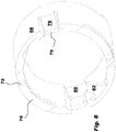
- the proximal end surface of the rotator 68 is arranged with flexible tongues 70 extending along the circumference, which are provided with proximally directed wedge-shaped ledges 72, Fig. 8 .
- the ledges 72 cooperate with wedge-shaped ratchets 74 on a distally directed surface of a circumferential ledge 76 of the mixing cylinder 50, such that the rotator 68 can only rotate in one direction in relation to the mixing cylinder 50, forming seventh connection means.
- the rotator 68 is further arranged with proximally directed, and inwardly flexing, tongues 78 having proximally directed end surfaces 79, Fig. 8 , which tongues 78 are arranged in grooves 80 on the inner surface of the rotator 68, which grooves 80 extend in the longitudinal direction of the device, forming eighth connection means. Further the longitudinal grooves 80 are cooperating with inclined grooves 82 that meet at the distal end of the longitudinal grooves 80, the function of which will be described below. Protrusions 84 are further arranged on the outer surface of the medicament delivery member guard 46, which protrusions 84 are arranged to cooperate with the grooves 80, 82 of the rotator 68, as will be described below.
- the device is intended to function as follows.
- the proximal end of the medicament container holder 12 protrudes through the proximal end of the medicament delivery member guard 46, Fig. 2 .
- This enables a medicament delivery member 14 to be attached to the proximal end of the medicament container holder 12.
- the proximal end surface 51 of the medicament container holder 12 is in contact with the circumferential ledge 47 of the medicament delivery member guard 46, whereby the latter is locked against distal movement, Fig. 9 .
- the next step is to perform the mixing. This is performed by rotating the mixing cylinder 50 in relation to the housing 10.
- the next step is to press the proximal end of the device against the medicament delivery site, such an injection site.
- the pressing of the device causes the medicament delivery member guard 46 to be pushed in the distal direction into the device and against the force of the medicament delivery member guard spring drive member 56, thereby exposing the medicament delivery member 16.
- the distance that the container holder 12 and its medicament delivery member 16 have been previously moved distally in relation to the guard, i.e. the length of the groove 48, correspond to a desired and set injection depth when the medicament delivery member is an injection needle.
- the distal movement of the medicament delivery member guard 46 causes its protrusions 84 to slide along the side surfaces of the inclined grooves 82 whereby the rotator 68 is turned.
- the medicament delivery mechanism is activated and a dose of medicament is delivered through the medicament delivery member 16, Fig. 12 .
- the lock member releases the drive member for delivering a dose.
- the actuation button acts directly on the plunger rod, whereby the latter is pushed in the proximal direction when the actuation button is pressed.
- the device may be provided with some kind of actuation locking and release means which acts to keep the actuation mechanism locked until a mixing operation is completed, in order to avoid unintentional activation until the device is ready for use.
- the device When a dose of medicament has been delivered, the device may be withdrawn from the site. This causes the medicament delivery member guard 46 to be again pushed in the proximal direction, whereby its protrusions 84 slide along the longitudinally directed grooves 80 of the rotator 68 until the protrusions 82 slide over and pass the tongues 78, after which the medicament delivery member guard 46 is covering the medicament delivery member. This will lock the medicament delivery member guard 46 against being pushed again in the distal direction in that its protrusions 84 will come in contact with the proximal end surfaces 79 of the tongues 78, which, in the case when the medicament delivery member is an injection needle, prevents unintentional needle sticks, Fig. 13 . The device may now be discarded.
Claims (17)
- Dispositif de distribution de médicament, comprenant :- un corps qui comprend un boîtier (10) et un support (12) de récipient à médicaments logeant un récipient à médicaments multi-chambres (18), ledit boîtier (10) et ledit support (12) de récipient à médicaments étant raccordés de manière interactive l'un à l'autre et pouvant se déplacer l'un par rapport à l'autre ; le support de récipient à médicaments comprenant un moyen de fixation (14) destiné à fixer un élément de distribution (16),- un mécanisme de protection contre les mélanges, raccordé de manière interactive au corps pour entraîner le support de récipient à médicaments à l'intérieur du boîtier, en assurant de ce fait une reconstitution,- dans lequel le mécanisme de protection contre les mélanges comprend une unité (50) formant cylindre de mélange et une protection tubulaire (46) d'élément de distribution de médicament, fonctionnellement raccordés au support (12) de récipient à médicaments, de telle sorte que, lors de l'actionnement du cylindre de mélange, le support (12) de récipient à médicaments est déplacé par rapport à la protection (46) de l'élément de distribution de médicament entre une position avant mélange, dans laquelle ledit moyen de fixation (14) dépasse d'une extrémité proximale de ladite protection (46) de l'élément de distribution de médicament, pour permettre la fixation d'un élément de distribution (16), et une position "après mélange", dans laquelle ledit moyen de fixation (14) et ledit élément de distribution fixé (16) sont positionnés à l'intérieur de la protection (46) de l'élément de distribution de médicament,caractérisé en ce que ledit mécanisme de protection contre les mélanges comprend en outre un verrou de protection et élément de libération (12, 51) fonctionnellement raccordé à ladite protection (46) et audit support (12) de récipient à médicaments, de telle sorte que ledit verrou de protection et élément de libération (12, 51) est conçu de façon à verrouiller ladite protection (46) quand le support de récipient se trouve en position avant mélange et à libérer ladite protection (46) quand le support de récipient est déplacé vers la position "après mélange", le déplacement dans la direction distale de l'élément de protection (46), quand le dispositif est appuyé contre un site de distribution de doses, provoquant une rotation d'un élément tournant (68) disposé dans ladite unité formant cylindre de mélange, et ledit mécanisme de protection contre les mélanges comprenant en outre un élément élastique (56) disposé fonctionnellement par rapport à ladite protection (46), pour pousser ladite protection (46) dans la direction proximale.
- Dispositif de distribution de médicament selon la revendication 1, dans lequel ladite rotation est provoquée par ledit élément tournant (68) comprenant au moins une gorge (82) inclinée par rapport à la direction longitudinale du dispositif, en coopération avec au moins une saillie disposée sur la protection (46) pendant le déplacement distal de ladite protection (46).
- Dispositif de distribution de médicament selon l'une quelconque des revendications précédentes, dans lequel l'élément tournant (68) comprend un premier moyen de verrouillage de la protection, raccordé de manière interactive à l'élément tournant (68) de telle sorte que le déplacement proximal de ladite protection (46), après le retrait d'un site de distribution de médicament, provoque un verrouillage de ladite protection (46) dans une position proximale recouvrant ledit élément de distribution de médicament.
- Dispositif de distribution de médicament selon l'une quelconque des revendications précédentes, dans lequel ledit mécanisme de protection contre les mélanges comprend un premier moyen de raccordement (38, 40), raccordant de manière interactive ledit boîtier (10) et ledit support (12) de récipient à médicaments, de façon à permettre un déplacement du support de récipient à médicaments à l'intérieur du boîtier.
- Dispositif de distribution de médicament selon la revendication 4, dans lequel ledit premier moyen de raccordement comprend des filetages coopérants (38, 40) sur ledit boîtier et sur ledit support de récipient à médicaments.
- Dispositif de distribution de médicament selon la revendication 3, dans lequel ledit premier moyen de verrouillage de la protection comprend au moins une languette élastique (78), dirigée dans la direction proximale, disposée vers ledit élément tournant (68), et au moins une saillie (84) disposée vers ladite protection (46), de telle sorte que, quand ladite protection (46) subit un déplacement proximal, ladite au moins une saillie (84) franchit ladite au moins une languette (78), et empêche de ce fait un déplacement distal ultérieur de ladite protection (46).
- Dispositif de distribution de médicament selon la revendication 1, dans lequel ledit support de récipient à médicaments et ladite protection (46) sont raccordés avec possibilité de coulissement, mais verrouillés en rotation de l'un par rapport à l'autre par un deuxième moyen de raccordement (42, 44, 46).
- Dispositif de distribution de médicament selon la revendication 1, dans lequel ledit cylindre de mélange (50) est disposé vers ladite protection (46) de telle sorte qu'ils soient raccordés avec possibilité de coulissement mais verrouillés en rotation de l'un par rapport à l'autre par un troisième moyen de raccordement (46, 50, 52, 54).
- Dispositif de distribution de médicament selon la revendication 8, dans lequel ledit cylindre de mélange (50) et un manchon de raccordement (58) sont raccordés à demeure l'un à l'autre par un quatrième moyen de raccordement (57).
- Dispositif de distribution de médicament selon la revendication 9, dans lequel ledit manchon de raccordement (58) et ledit boîtier sont raccordés l'un à l'autre par un cinquième moyen de raccordement (58, 64, 66), qui empêche un déplacement longitudinal de l'un par rapport à l'autre, mais qui permet une rotation de l'un par rapport à l'autre.
- Dispositif de distribution de médicament selon la revendication 10, dans lequel ledit élément tournant (68) et ledit manchon de raccordement (58) sont raccordés l'un à l'autre par un sixième moyen de raccordement, qui empêche un déplacement longitudinal de l'un par rapport à l'autre mais qui permet une rotation partielle de l'un par rapport à l'autre, et ledit manchon de raccordement (58) et ledit élément tournant (68) étant disposés de manière coaxiale à l'intérieur dudit cylindre de mélange (50).
- Dispositif de distribution de médicament selon la revendication 11, dans lequel ledit élément tournant (68) et ledit cylindre de mélange (50) sont raccordés l'un à l'autre, avec possibilité de rotation dans une seule direction, par un septième moyen de raccordement (72, 74, 76).
- Dispositif de distribution de médicament selon l'une quelconque des revendications précédentes, comprenant en outre un moyen d'entraînement (28, 30) disposé à l'intérieur dudit boîtier et conçu de façon à entraîner un butoir (20) disposé à l'intérieur dudit récipient multi-chambres (18).
- Dispositif de distribution de médicament selon la revendication 13, dans lequel ledit moyen d'entraînement comprend une tige de piston (28) et un élément de force (30), agissant fonctionnellement sur ladite tige de piston pour la pousser dans la direction proximale.
- Dispositif de distribution de médicament selon la revendication 13 ou 14, qui comprend en outre un moyen de retenue (32, 34) pour maintenir ledit moyen d'entraînement dans un état de pré-tension.
- Dispositif de distribution de médicament selon la revendication 15, qui comprend en outre un moyen d'activation (36), susceptible d'agir sur ledit moyen de retenue (32, 34) pour libérer le moyen d'entraînement de son état de pré-tension.
- Dispositif de distribution de médicament selon l'une quelconque des revendications précédentes, le dispositif étant un dispositif pour injection.
Applications Claiming Priority (3)
| Application Number | Priority Date | Filing Date | Title |
|---|---|---|---|
| US41507010P | 2010-11-18 | 2010-11-18 | |
| SE1051212 | 2010-11-18 | ||
| PCT/SE2011/051391 WO2012067583A1 (fr) | 2010-11-18 | 2011-11-18 | Dispositif de distribution de médicament |
Publications (3)
| Publication Number | Publication Date |
|---|---|
| EP2640448A1 EP2640448A1 (fr) | 2013-09-25 |
| EP2640448A4 EP2640448A4 (fr) | 2016-06-01 |
| EP2640448B1 true EP2640448B1 (fr) | 2018-10-03 |
Family
ID=46084297
Family Applications (1)
| Application Number | Title | Priority Date | Filing Date |
|---|---|---|---|
| EP11841646.0A Active EP2640448B1 (fr) | 2010-11-18 | 2011-11-18 | Dispositif de distribution de médicament |
Country Status (8)
| Country | Link |
|---|---|
| US (1) | US9132235B2 (fr) |
| EP (1) | EP2640448B1 (fr) |
| JP (1) | JP5721849B2 (fr) |
| CN (1) | CN103282067B (fr) |
| AU (1) | AU2011329574B9 (fr) |
| DK (1) | DK2640448T3 (fr) |
| TW (2) | TWI476024B (fr) |
| WO (1) | WO2012067583A1 (fr) |
Families Citing this family (16)
| Publication number | Priority date | Publication date | Assignee | Title |
|---|---|---|---|---|
| KR101699985B1 (ko) * | 2010-01-25 | 2017-01-25 | 테크레스 에스.피.에이. | 2성분 혼합물의 조제 및 투여 장치 |
| JP5807021B2 (ja) | 2010-02-18 | 2015-11-10 | サノフィ−アベンティス・ドイチュラント・ゲゼルシャフト・ミット・ベシュレンクテル・ハフツング | 自動注射器 |
| EP2399635A1 (fr) | 2010-06-28 | 2011-12-28 | Sanofi-Aventis Deutschland GmbH | Auto-injecteur |
| TWI464003B (zh) | 2010-11-18 | 2014-12-11 | Shl Group Ab | 藥物輸送裝置 |
| EP2640449B1 (fr) | 2010-11-18 | 2015-08-26 | SHL Group AB | Dispositif de distribution de médicament |
| EP2468330A1 (fr) | 2010-12-21 | 2012-06-27 | Sanofi-Aventis Deutschland GmbH | Auto-injecteur |
| USRE48593E1 (en) | 2010-12-21 | 2021-06-15 | Sanofi-Aventis Deutschland Gmbh | Auto-injector |
| EP2468333A1 (fr) | 2010-12-21 | 2012-06-27 | Sanofi-Aventis Deutschland GmbH | Auto-injecteur |
| US8747286B1 (en) * | 2011-03-16 | 2014-06-10 | Mark H. Simon | Exercise apparatus |
| TWI477256B (zh) * | 2012-01-19 | 2015-03-21 | Bionime Corp | 穿刺裝置 |
| WO2014082959A1 (fr) | 2012-11-29 | 2014-06-05 | Novo Nordisk A/S | Dispositif d'injection ayant un protecteur d'aiguille intégré |
| EP2823841A1 (fr) | 2013-07-09 | 2015-01-14 | Sanofi-Aventis Deutschland GmbH | Auto-injecteur |
| WO2015071123A1 (fr) | 2013-11-15 | 2015-05-21 | Carebay Europe Ltd | Dispositif d'administration de médicament |
| EP2923714A1 (fr) | 2014-03-28 | 2015-09-30 | Sanofi-Aventis Deutschland GmbH | Auto-injecteur declenché par contact avec la peau |
| WO2015196420A1 (fr) * | 2014-06-26 | 2015-12-30 | 群康生技股份有限公司 | Mécanisme de commutation circulaire pour seringue |
| TW201603847A (zh) * | 2014-07-01 | 2016-02-01 | 賽諾菲公司 | 注射裝置及組裝方法 |
Family Cites Families (24)
| Publication number | Priority date | Publication date | Assignee | Title |
|---|---|---|---|---|
| DK0693949T3 (da) * | 1994-02-14 | 1999-02-15 | Sanofi Sa | Injektionsmodul til en sprøjte |
| FR2815543B1 (fr) * | 2000-10-19 | 2003-10-24 | Sedat | Seringue d'auto-injection d'un melange extemporane |
| ATE306958T1 (de) * | 2001-06-20 | 2005-11-15 | Becton Dickinson Co | Schutzhülse für vorgefüllte spritzen |
| GB0200444D0 (en) * | 2002-01-10 | 2002-02-27 | Owen Mumford Ltd | Improvements relating to medical injection devices |
| AU2003208948A1 (en) * | 2002-03-13 | 2003-09-29 | Eli Lilly And Company | Method of treating a medical condition with a portable medication delivery device |
| DE10340585A1 (de) * | 2003-09-03 | 2005-04-07 | Tecpharma Licensing Ag | Verabreichungsvorrichtung mit Mehrkammerampulle und Mischsperre |
| CN101119761B (zh) * | 2004-11-24 | 2010-08-18 | Shl医药公司 | 注射设备 |
| DE102004063652B4 (de) * | 2004-12-31 | 2007-02-08 | Tecpharma Licensing Ag | Vorrichtung zur dosierten Verabreichung eines fluiden Produkts mit koaxialer Dosisanzeige |
| EP1919540B1 (fr) * | 2005-09-01 | 2016-05-18 | Owen Mumford Limited | Ensemble de coiffe d aiguille |
| WO2007131013A1 (fr) * | 2006-05-03 | 2007-11-15 | Antares Pharma, Inc. | Injecteur de reconstitution à deux étages |
| GB2437924B (en) * | 2006-05-11 | 2010-12-22 | Owen Mumford Ltd | Injection device |
| FR2905273B1 (fr) * | 2006-09-06 | 2009-04-03 | Becton Dickinson France Soc Pa | Dispositif d'injection automatique avec moyen de temporisation. |
| ATE473772T1 (de) * | 2007-01-17 | 2010-07-15 | Shl Group Ab | Vorrichtung zur abgabe von medikamenten |
| JP5128658B2 (ja) * | 2007-04-05 | 2013-01-23 | テクファーマ・ライセンシング・アクチェンゲゼルシャフト | 機能的な駆動素子を備える投与装置 |
| DE102007054019A1 (de) * | 2007-11-13 | 2009-05-14 | Tecpharma Licensing Ag | Injektionsvorrichtung mit betätigungsaktivierter Kupplung |
| US8926558B2 (en) * | 2008-07-04 | 2015-01-06 | Shl Group Ab | Medicament delivery device with mixing mechanism |
| WO2010029043A1 (fr) | 2008-09-09 | 2010-03-18 | Shl Group Ab | Dispositif d'administration de médicament |
| WO2010081489A1 (fr) * | 2009-01-15 | 2010-07-22 | Tecpharma Licensing Ag | Dispositif pour administrer un produit injectable |
| WO2010115670A1 (fr) * | 2009-04-03 | 2010-10-14 | Shl Group Ab | Dispositif d'administration de médicaments |
| AR076720A1 (es) | 2009-06-02 | 2011-06-29 | Sanofi Aventis Deutschland | Modulo medicinal con protector de agua |
| EP2536456B1 (fr) * | 2010-02-17 | 2021-04-28 | Sanofi-Aventis Deutschland GmbH | Dispositif d'injection automatique avec ressort de torsion |
| JP5950828B2 (ja) | 2010-02-17 | 2016-07-13 | サノフィ−アベンティス・ドイチュラント・ゲゼルシャフト・ミット・ベシュレンクテル・ハフツング | 注射デバイス |
| TWI464003B (zh) | 2010-11-18 | 2014-12-11 | Shl Group Ab | 藥物輸送裝置 |
| EP2640449B1 (fr) | 2010-11-18 | 2015-08-26 | SHL Group AB | Dispositif de distribution de médicament |
-
2011
- 2011-11-17 TW TW100141946A patent/TWI476024B/zh not_active IP Right Cessation
- 2011-11-17 TW TW100141947A patent/TWI459984B/zh not_active IP Right Cessation
- 2011-11-18 EP EP11841646.0A patent/EP2640448B1/fr active Active
- 2011-11-18 JP JP2013539796A patent/JP5721849B2/ja not_active Expired - Fee Related
- 2011-11-18 WO PCT/SE2011/051391 patent/WO2012067583A1/fr active Application Filing
- 2011-11-18 US US13/885,887 patent/US9132235B2/en active Active
- 2011-11-18 CN CN201180063967.9A patent/CN103282067B/zh not_active Expired - Fee Related
- 2011-11-18 DK DK11841646.0T patent/DK2640448T3/en active
- 2011-11-18 AU AU2011329574A patent/AU2011329574B9/en not_active Ceased
Non-Patent Citations (1)
| Title |
|---|
| None * |
Also Published As
| Publication number | Publication date |
|---|---|
| JP5721849B2 (ja) | 2015-05-20 |
| TWI476024B (zh) | 2015-03-11 |
| AU2011329574A1 (en) | 2013-05-02 |
| EP2640448A1 (fr) | 2013-09-25 |
| EP2640448A4 (fr) | 2016-06-01 |
| US20130237905A1 (en) | 2013-09-12 |
| TW201231116A (en) | 2012-08-01 |
| TW201225999A (en) | 2012-07-01 |
| US9132235B2 (en) | 2015-09-15 |
| TWI459984B (zh) | 2014-11-11 |
| WO2012067583A1 (fr) | 2012-05-24 |
| DK2640448T3 (en) | 2018-11-12 |
| JP2014500768A (ja) | 2014-01-16 |
| AU2011329574B9 (en) | 2015-05-07 |
| AU2011329574B2 (en) | 2014-12-11 |
| CN103282067A (zh) | 2013-09-04 |
| CN103282067B (zh) | 2015-10-21 |
Similar Documents
| Publication | Publication Date | Title |
|---|---|---|
| EP2640448B1 (fr) | Dispositif de distribution de médicament | |
| AU2012316786B2 (en) | Medical delivery device with an initial locked state, intermediate priming state and a medicament delivery state | |
| US9579458B2 (en) | Medicament delivery device | |
| EP2326370B1 (fr) | Injecteur médical avec activation par manchon coulissant | |
| JP5373916B2 (ja) | 連結された本体部分を備える医療用インジェクター | |
| EP2640449B1 (fr) | Dispositif de distribution de médicament | |
| TWI576128B (zh) | 藥物輸送裝置 | |
| EP3202442B1 (fr) | Unité de retenue de cartouche de médicament, et dispositif d'injection de médicament la comprenant | |
| US8486006B2 (en) | Medical injector with button activation | |
| US11607497B2 (en) | Medicament delivery device | |
| JP2013523314A (ja) | 薬剤送出装置 | |
| JP2016539741A (ja) | 投与量選択可能注射装置 | |
| CN109310824B (zh) | 药剂输送装置 | |
| CN114728128A (zh) | 用于药剂输送装置的容器保持架组件及药剂输送装置 |
Legal Events
| Date | Code | Title | Description |
|---|---|---|---|
| PUAI | Public reference made under article 153(3) epc to a published international application that has entered the european phase |
Free format text: ORIGINAL CODE: 0009012 |
|
| 17P | Request for examination filed |
Effective date: 20130607 |
|
| AK | Designated contracting states |
Kind code of ref document: A1 Designated state(s): AL AT BE BG CH CY CZ DE DK EE ES FI FR GB GR HR HU IE IS IT LI LT LU LV MC MK MT NL NO PL PT RO RS SE SI SK SM TR |
|
| DAX | Request for extension of the european patent (deleted) | ||
| RA4 | Supplementary search report drawn up and despatched (corrected) |
Effective date: 20160502 |
|
| RIC1 | Information provided on ipc code assigned before grant |
Ipc: A61M 5/24 20060101ALI20160425BHEP Ipc: A61M 5/32 20060101AFI20160425BHEP |
|
| RAP1 | Party data changed (applicant data changed or rights of an application transferred) |
Owner name: SHL GROUP AB |
|
| GRAP | Despatch of communication of intention to grant a patent |
Free format text: ORIGINAL CODE: EPIDOSNIGR1 |
|
| INTG | Intention to grant announced |
Effective date: 20171207 |
|
| RIN1 | Information on inventor provided before grant (corrected) |
Inventor name: HOLMQVIST, ANDERS |
|
| GRAJ | Information related to disapproval of communication of intention to grant by the applicant or resumption of examination proceedings by the epo deleted |
Free format text: ORIGINAL CODE: EPIDOSDIGR1 |
|
| INTC | Intention to grant announced (deleted) | ||
| GRAP | Despatch of communication of intention to grant a patent |
Free format text: ORIGINAL CODE: EPIDOSNIGR1 |
|
| INTG | Intention to grant announced |
Effective date: 20180531 |
|
| GRAS | Grant fee paid |
Free format text: ORIGINAL CODE: EPIDOSNIGR3 |
|
| GRAA | (expected) grant |
Free format text: ORIGINAL CODE: 0009210 |
|
| AK | Designated contracting states |
Kind code of ref document: B1 Designated state(s): AL AT BE BG CH CY CZ DE DK EE ES FI FR GB GR HR HU IE IS IT LI LT LU LV MC MK MT NL NO PL PT RO RS SE SI SK SM TR |
|
| REG | Reference to a national code |
Ref country code: GB Ref legal event code: FG4D |
|
| REG | Reference to a national code |
Ref country code: CH Ref legal event code: EP Ref country code: AT Ref legal event code: REF Ref document number: 1047955 Country of ref document: AT Kind code of ref document: T Effective date: 20181015 |
|
| REG | Reference to a national code |
Ref country code: FR Ref legal event code: PLFP Year of fee payment: 8 |
|
| REG | Reference to a national code |
Ref country code: IE Ref legal event code: FG4D Ref country code: DE Ref legal event code: R096 Ref document number: 602011052642 Country of ref document: DE |
|
| REG | Reference to a national code |
Ref country code: SE Ref legal event code: TRGR |
|
| REG | Reference to a national code |
Ref country code: DK Ref legal event code: T3 Effective date: 20181106 |
|
| REG | Reference to a national code |
Ref country code: NL Ref legal event code: MP Effective date: 20181003 |
|
| REG | Reference to a national code |
Ref country code: LT Ref legal event code: MG4D |
|
| REG | Reference to a national code |
Ref country code: AT Ref legal event code: MK05 Ref document number: 1047955 Country of ref document: AT Kind code of ref document: T Effective date: 20181003 |
|
| PG25 | Lapsed in a contracting state [announced via postgrant information from national office to epo] |
Ref country code: NL Free format text: LAPSE BECAUSE OF FAILURE TO SUBMIT A TRANSLATION OF THE DESCRIPTION OR TO PAY THE FEE WITHIN THE PRESCRIBED TIME-LIMIT Effective date: 20181003 |
|
| REG | Reference to a national code |
Ref country code: CH Ref legal event code: PUE Owner name: SHL MEDICAL AG, CH Free format text: FORMER OWNER: SHL GROUP AB, SE |
|
| PG25 | Lapsed in a contracting state [announced via postgrant information from national office to epo] |
Ref country code: ES Free format text: LAPSE BECAUSE OF FAILURE TO SUBMIT A TRANSLATION OF THE DESCRIPTION OR TO PAY THE FEE WITHIN THE PRESCRIBED TIME-LIMIT Effective date: 20181003 Ref country code: LV Free format text: LAPSE BECAUSE OF FAILURE TO SUBMIT A TRANSLATION OF THE DESCRIPTION OR TO PAY THE FEE WITHIN THE PRESCRIBED TIME-LIMIT Effective date: 20181003 Ref country code: HR Free format text: LAPSE BECAUSE OF FAILURE TO SUBMIT A TRANSLATION OF THE DESCRIPTION OR TO PAY THE FEE WITHIN THE PRESCRIBED TIME-LIMIT Effective date: 20181003 Ref country code: CZ Free format text: LAPSE BECAUSE OF FAILURE TO SUBMIT A TRANSLATION OF THE DESCRIPTION OR TO PAY THE FEE WITHIN THE PRESCRIBED TIME-LIMIT Effective date: 20181003 Ref country code: PL Free format text: LAPSE BECAUSE OF FAILURE TO SUBMIT A TRANSLATION OF THE DESCRIPTION OR TO PAY THE FEE WITHIN THE PRESCRIBED TIME-LIMIT Effective date: 20181003 Ref country code: LT Free format text: LAPSE BECAUSE OF FAILURE TO SUBMIT A TRANSLATION OF THE DESCRIPTION OR TO PAY THE FEE WITHIN THE PRESCRIBED TIME-LIMIT Effective date: 20181003 Ref country code: BG Free format text: LAPSE BECAUSE OF FAILURE TO SUBMIT A TRANSLATION OF THE DESCRIPTION OR TO PAY THE FEE WITHIN THE PRESCRIBED TIME-LIMIT Effective date: 20190103 Ref country code: FI Free format text: LAPSE BECAUSE OF FAILURE TO SUBMIT A TRANSLATION OF THE DESCRIPTION OR TO PAY THE FEE WITHIN THE PRESCRIBED TIME-LIMIT Effective date: 20181003 Ref country code: IS Free format text: LAPSE BECAUSE OF FAILURE TO SUBMIT A TRANSLATION OF THE DESCRIPTION OR TO PAY THE FEE WITHIN THE PRESCRIBED TIME-LIMIT Effective date: 20190203 Ref country code: NO Free format text: LAPSE BECAUSE OF FAILURE TO SUBMIT A TRANSLATION OF THE DESCRIPTION OR TO PAY THE FEE WITHIN THE PRESCRIBED TIME-LIMIT Effective date: 20190103 Ref country code: AT Free format text: LAPSE BECAUSE OF FAILURE TO SUBMIT A TRANSLATION OF THE DESCRIPTION OR TO PAY THE FEE WITHIN THE PRESCRIBED TIME-LIMIT Effective date: 20181003 |
|
| PG25 | Lapsed in a contracting state [announced via postgrant information from national office to epo] |
Ref country code: RS Free format text: LAPSE BECAUSE OF FAILURE TO SUBMIT A TRANSLATION OF THE DESCRIPTION OR TO PAY THE FEE WITHIN THE PRESCRIBED TIME-LIMIT Effective date: 20181003 Ref country code: GR Free format text: LAPSE BECAUSE OF FAILURE TO SUBMIT A TRANSLATION OF THE DESCRIPTION OR TO PAY THE FEE WITHIN THE PRESCRIBED TIME-LIMIT Effective date: 20190104 Ref country code: PT Free format text: LAPSE BECAUSE OF FAILURE TO SUBMIT A TRANSLATION OF THE DESCRIPTION OR TO PAY THE FEE WITHIN THE PRESCRIBED TIME-LIMIT Effective date: 20190203 Ref country code: AL Free format text: LAPSE BECAUSE OF FAILURE TO SUBMIT A TRANSLATION OF THE DESCRIPTION OR TO PAY THE FEE WITHIN THE PRESCRIBED TIME-LIMIT Effective date: 20181003 |
|
| REG | Reference to a national code |
Ref country code: DE Ref legal event code: R081 Ref document number: 602011052642 Country of ref document: DE Owner name: SHL MEDICAL AG, CH Free format text: FORMER OWNER: SHL GROUP AB, NACKA STRAND, SE |
|
| REG | Reference to a national code |
Ref country code: DE Ref legal event code: R097 Ref document number: 602011052642 Country of ref document: DE |
|
| PG25 | Lapsed in a contracting state [announced via postgrant information from national office to epo] |
Ref country code: LU Free format text: LAPSE BECAUSE OF NON-PAYMENT OF DUE FEES Effective date: 20181118 Ref country code: IT Free format text: LAPSE BECAUSE OF FAILURE TO SUBMIT A TRANSLATION OF THE DESCRIPTION OR TO PAY THE FEE WITHIN THE PRESCRIBED TIME-LIMIT Effective date: 20181003 |
|
| PLBE | No opposition filed within time limit |
Free format text: ORIGINAL CODE: 0009261 |
|
| STAA | Information on the status of an ep patent application or granted ep patent |
Free format text: STATUS: NO OPPOSITION FILED WITHIN TIME LIMIT |
|
| REG | Reference to a national code |
Ref country code: BE Ref legal event code: MM Effective date: 20181130 |
|
| REG | Reference to a national code |
Ref country code: IE Ref legal event code: MM4A |
|
| REG | Reference to a national code |
Ref country code: GB Ref legal event code: 732E Free format text: REGISTERED BETWEEN 20190801 AND 20190807 |
|
| PG25 | Lapsed in a contracting state [announced via postgrant information from national office to epo] |
Ref country code: SK Free format text: LAPSE BECAUSE OF FAILURE TO SUBMIT A TRANSLATION OF THE DESCRIPTION OR TO PAY THE FEE WITHIN THE PRESCRIBED TIME-LIMIT Effective date: 20181003 Ref country code: RO Free format text: LAPSE BECAUSE OF FAILURE TO SUBMIT A TRANSLATION OF THE DESCRIPTION OR TO PAY THE FEE WITHIN THE PRESCRIBED TIME-LIMIT Effective date: 20181003 Ref country code: MC Free format text: LAPSE BECAUSE OF FAILURE TO SUBMIT A TRANSLATION OF THE DESCRIPTION OR TO PAY THE FEE WITHIN THE PRESCRIBED TIME-LIMIT Effective date: 20181003 Ref country code: SM Free format text: LAPSE BECAUSE OF FAILURE TO SUBMIT A TRANSLATION OF THE DESCRIPTION OR TO PAY THE FEE WITHIN THE PRESCRIBED TIME-LIMIT Effective date: 20181003 Ref country code: EE Free format text: LAPSE BECAUSE OF FAILURE TO SUBMIT A TRANSLATION OF THE DESCRIPTION OR TO PAY THE FEE WITHIN THE PRESCRIBED TIME-LIMIT Effective date: 20181003 |
|
| 26N | No opposition filed |
Effective date: 20190704 |
|
| PG25 | Lapsed in a contracting state [announced via postgrant information from national office to epo] |
Ref country code: SI Free format text: LAPSE BECAUSE OF FAILURE TO SUBMIT A TRANSLATION OF THE DESCRIPTION OR TO PAY THE FEE WITHIN THE PRESCRIBED TIME-LIMIT Effective date: 20181003 Ref country code: IE Free format text: LAPSE BECAUSE OF NON-PAYMENT OF DUE FEES Effective date: 20181118 |
|
| PG25 | Lapsed in a contracting state [announced via postgrant information from national office to epo] |
Ref country code: BE Free format text: LAPSE BECAUSE OF NON-PAYMENT OF DUE FEES Effective date: 20181130 |
|
| PG25 | Lapsed in a contracting state [announced via postgrant information from national office to epo] |
Ref country code: MT Free format text: LAPSE BECAUSE OF NON-PAYMENT OF DUE FEES Effective date: 20181118 |
|
| PG25 | Lapsed in a contracting state [announced via postgrant information from national office to epo] |
Ref country code: TR Free format text: LAPSE BECAUSE OF FAILURE TO SUBMIT A TRANSLATION OF THE DESCRIPTION OR TO PAY THE FEE WITHIN THE PRESCRIBED TIME-LIMIT Effective date: 20181003 |
|
| PG25 | Lapsed in a contracting state [announced via postgrant information from national office to epo] |
Ref country code: MK Free format text: LAPSE BECAUSE OF NON-PAYMENT OF DUE FEES Effective date: 20181003 Ref country code: HU Free format text: LAPSE BECAUSE OF FAILURE TO SUBMIT A TRANSLATION OF THE DESCRIPTION OR TO PAY THE FEE WITHIN THE PRESCRIBED TIME-LIMIT; INVALID AB INITIO Effective date: 20111118 Ref country code: CY Free format text: LAPSE BECAUSE OF FAILURE TO SUBMIT A TRANSLATION OF THE DESCRIPTION OR TO PAY THE FEE WITHIN THE PRESCRIBED TIME-LIMIT Effective date: 20181003 |
|
| PGFP | Annual fee paid to national office [announced via postgrant information from national office to epo] |
Ref country code: DK Payment date: 20221111 Year of fee payment: 12 |
|
| P01 | Opt-out of the competence of the unified patent court (upc) registered |
Effective date: 20230425 |
|
| PGFP | Annual fee paid to national office [announced via postgrant information from national office to epo] |
Ref country code: GB Payment date: 20231006 Year of fee payment: 13 |
|
| PGFP | Annual fee paid to national office [announced via postgrant information from national office to epo] |
Ref country code: SE Payment date: 20231010 Year of fee payment: 13 Ref country code: FR Payment date: 20231024 Year of fee payment: 13 Ref country code: DE Payment date: 20231003 Year of fee payment: 13 Ref country code: CH Payment date: 20231201 Year of fee payment: 13 |