EP2638826A1 - Klappbares Display und Kühlgerät, klappbares Display und Regal des klappbaren Displays - Google Patents
Klappbares Display und Kühlgerät, klappbares Display und Regal des klappbaren Displays Download PDFInfo
- Publication number
- EP2638826A1 EP2638826A1 EP12461508.9A EP12461508A EP2638826A1 EP 2638826 A1 EP2638826 A1 EP 2638826A1 EP 12461508 A EP12461508 A EP 12461508A EP 2638826 A1 EP2638826 A1 EP 2638826A1
- Authority
- EP
- European Patent Office
- Prior art keywords
- bendable
- shelf
- foldable stand
- wall
- cooling device
- Prior art date
- Legal status (The legal status is an assumption and is not a legal conclusion. Google has not performed a legal analysis and makes no representation as to the accuracy of the status listed.)
- Withdrawn
Links
Images


Classifications
-
- A—HUMAN NECESSITIES
- A47—FURNITURE; DOMESTIC ARTICLES OR APPLIANCES; COFFEE MILLS; SPICE MILLS; SUCTION CLEANERS IN GENERAL
- A47F—SPECIAL FURNITURE, FITTINGS, OR ACCESSORIES FOR SHOPS, STOREHOUSES, BARS, RESTAURANTS OR THE LIKE; PAYING COUNTERS
- A47F3/00—Show cases or show cabinets
- A47F3/04—Show cases or show cabinets air-conditioned, refrigerated
- A47F3/0439—Cases or cabinets of the open type
- A47F3/0443—Cases or cabinets of the open type with forced air circulation
- A47F3/0447—Cases or cabinets of the open type with forced air circulation with air curtains
-
- A—HUMAN NECESSITIES
- A47—FURNITURE; DOMESTIC ARTICLES OR APPLIANCES; COFFEE MILLS; SPICE MILLS; SUCTION CLEANERS IN GENERAL
- A47F—SPECIAL FURNITURE, FITTINGS, OR ACCESSORIES FOR SHOPS, STOREHOUSES, BARS, RESTAURANTS OR THE LIKE; PAYING COUNTERS
- A47F5/00—Show stands, hangers, or shelves characterised by their constructional features
- A47F5/10—Adjustable or foldable or dismountable display stands
- A47F5/11—Adjustable or foldable or dismountable display stands made of cardboard, paper or the like
- A47F5/112—Adjustable or foldable or dismountable display stands made of cardboard, paper or the like hand-folded from sheet material
- A47F5/116—Shelving racks
Definitions
- the subject of the invention is a set or unit of a foldable stand and a cooling device, a foldable stand and a shelf of a foldable stand formed, in case of the foldable stand and shelf of the foldable stand, from foldable material, such as cardboard, corrugated cardboard, paper and sheets of plastic.
- foldable materials such as cardboard, corrugated cardboard and paper
- the latter include trays, pallets, displaying devices and particularly stands and their elements.
- cardboard is recyclable and suitable for placing inscriptions and pictures.
- the stands and their elements can be used as information carriers, particularly after placing advertisement and commercial information on them.
- the cardboard from which the displays are formed, particularly stands can easily be removed and recycled.
- products made of cardboard are environmentally friendly, have a simple construction and are relatively cheap.
- shelf system capable of being assembled from blanks of foldable material, such as in particular corrugated cardboard, cardboard or the like, which can be folded up to form structural elements of the shelf system
- a system with shelves which can comprise elements formed from foldable material, in particular corrugated cardboard.
- the said system comprises vertical supporting columns between which shelves are placed.
- vertical supporting columns are made as empty inside, closed profiles made of sheets whose endings are folded inside the profile.
- the shelves are empty profiles with cuts on both sides which include the margins of the sheets folded inwards, from which the vertical supporting columns are made.
- a display stand made of foldable paper material comprises a base, a back panel and side panels, and at least one shelf placed between the panels.
- the shelf has hinged mounting and it can move from an operative horizontal position to an upright assembled position.
- WO 2011078826 A1 entitled “Foldable product display stand” features a foldable, easily-assembled display stand installed from elements made of paper, corrugated cardboard and plastic, used for displaying various products in shops, supermarkets and workshops.
- the aim of this invention is to create a set or unit of a foldable stand and a cooling device, whose construction would be simple, and whose dimensions would be small after folding, which would facilitate carrying it from one place to another.
- the subject of this invention is a unit of a foldable stand and a cooling device, where the foldable stand is made from bendable material and with its lower part is nestled on the cooling device and partly surrounds the cooling device.
- the foldable stand of this unit comprises panels and at least one bendable shelf having a shape of a spatial body, where at least a front panel and a back panel of the foldable stand is bendable.
- each bending line divides the lower wall into component elements, each of which has supporting elements or bearing elements with inner supporting surfaces or bearing surfaces, and the inner supporting surfaces lying opposite each other of two neighbouring supporting elements attached to the lower wall contact and act on each other after stretching the bendable shelf preventing the bendable shelf from bending with a convexity downwards, and each of the catches together with the opening of the side panels of the foldable stand forms a side hinge allowing self-aligning movement of the component element of the bendable shelf in respect to the side panel of the foldable stand.
- the bendable shelf of the foldable stand has a front wall, a back wall and a top wall, and the bearing elements having the internal bearing surfaces are formed on the front wall, the back wall and the top wall of the bendable shelf separated in a plane running across through the bending line and situated at an angle in relation to the lower wall of the bendable shelf.
- the front panel of the foldable stand is lower than the side panels of the stand, and the bendable shelves are situated not lower than the top edge of the front panel of the foldable stand.
- the back panel of the stand has connected each other an inner part and an outer part, which is at a distance from the inner part, whose height is lower than the height of the side panels of the foldable stand, and which has openings connecting the inner space of the foldable stand with the space created between the inner part and outer part of the back panel.
- a top inner element may be placed on which a top stiffening element is placed and a topper.
- the outer and inner surfaces of the foldable stand may be used for placing advertisements or information. Therefore, on the visible inner and outer surfaces of the side panels, the front panel, the back panel, the bendable shelves as well as the top stiffening element and the topper advertisements and information can be placed.
- the front wall and a part of the top wall of the bendable shelf are formed from a strip of bendable material which is an extension of the lower wall of the bendable shelf towards the front, whereas the back wall and the part of the top wall of the bendable shelf are formed from a strip of bendable material which is an extension of the lower wall of the bendable shelf towards the back.
- the front wall, the top wall and the back wall of the bendable shelf are formed from a strip of bendable material which is an extension of the lower wall towards the front, or the back wall, the top wall and the front wall of the bendable shelf are formed from a strip of bendable material which is an extension of the lower wall towards the back.
- the bendable shelf comprises layers of bendable material connected with the elements of the lower wall of the bendable shelf, which are cut crosswise throughout their thickness, which form the bearing elements with the internal bearing surfaces.
- a tilting panel is mounted to the front wall of the bendable shelf.
- the tilting panel forms an outstanding element of the bendable shelf, which protrudes above the top surface of the top wall of the bendable shelf in a position when the shelf is stretched and spaces the side panels of the stand.
- the bendable shelf can have stabilizing projections, which protrude beyond the sides of the bendable shelf, and which are insertable in the additional openings.
- a blocking element is placed, with the letter 'C' shaped cross-section, whose central part forms a side and/or central wall of the bendable shelf.
- the unit of the cooling device and the foldable stand has a cooling system, whose cooled air chamber, formed between the inner part of the back panel and the outer part of the back panel, which is at a distance from the inner part, has an inlet, situated above an outlet of a stream of cooled air generated by the cooling device, and outlets formed in the inner part of the back panel of the foldable stand and connecting the chamber formed between the inner part and outer part of the back panel with the inner part of the foldable stand situated above the bendable shelves, from which the stream of air flows to the inlet of the cooling device after descending from the bendable shelves, whose front surfaces are moved backwards in relation to the plane in which the front panel of the foldable stand is situated.
- the idea of the invention relates to a foldable stand, which in lower area of its side panels and a back panel has ports or through openings which allow the flow of the stream of air which cools a cooling device.
- the idea of the invention relates also to the bendable shelf made from bendable material on which a strip from textile material or bendable plastic is stuck or adhered in the area of the bending line, along which the central hinge is formed which allows bending of the bendable shelf.
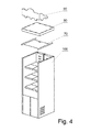
- Figs. 1 and 2 show basic elements of a first embodiment of a set or a unit of a foldable stand and a cooling device
- Fig. 1 shows an axonometric view of a first variant of a foldable stand made from bendable material
- Fig. 2 shows an axonometric view of a cooling unit compactable with the foldable stand made from bendable material
- Fig. 3 shows an axonometric expanded view of set elements of the first variant of the foldable stand made from bendable material
- Fig. 4 shows a course of the final stage of assembling the foldable stand
- Figs. 1 and 2 show basic elements of a first embodiment of a set or a unit of a foldable stand and a cooling device
- Fig. 1 shows an axonometric view of a first variant of a foldable stand made from bendable material
- Fig. 2 shows an axonometric view of a cooling unit compactable with the foldable stand made from bendable material
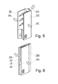
- FIG. 5 and 6 show steps of assembling the first variant of the foldable stand made from bendable material
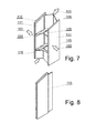
- Figs. 7 and 8 show steps of assembling the next variant of the foldable stand made from bendable material
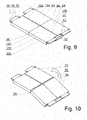
- Figs. 9, 10 , 11 and 12 show an axonometric view of the first variant of a bendable shelf made from bendable material
- Fig. 13 shows a pattern of the first variant of the bendable shelf made from bendable material
- Fig. 14 shows a pattern of a blocking element of the bendable shelf
- Figs. 15, 16 , 17 and 18 show the second variant of the bendable shelf of the foldable stand
- Fig. 19 shows a pattern of the next variant of the shelf made from bendable material
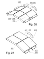
- Fig. 20 shows the next variant of the bendable shelf of the foldable stand
- Fig. 21 shows the next variant of the bendable shelf of the foldable stand
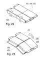
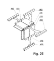
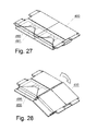
- Figs. 22, 23 , 24, 25 , 26 , 27 and 28 show next variants of the example of the bendable shelf with a tilting element or protruding element of the bendable shelf, which protrudes above the top surface of the top wall of the shelf
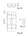
- Figs. 29, 30 and 31 show patterns of elements of the bendable shelf with the tilting element or protruding element of the bendable shelf, which protrudes above the top surface of the top wall of the shelf shown in Fig. 22
- Fig. 32 shows the next variant of the bendable shelf with blocking elements of the bendable shelf in the form of a clip
- Fig. 33 shows the next variant of the bendable shelf of the foldable stand
- Fig. 34 shows the next variant of the bendable shelf of the foldable stand
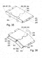
- Figs. 35 and 36 show the next variant of the bendable shelf of the foldable stand
- Fig. 37 shows the axonometric view of the foldable stand with the bendable shelves without catches and removed side panel made from bendable material
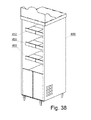
- Fig. 38 shows the set of the foldable stand and cooling device
- Fig. 39 shows a flow path of the stream of air in the set of the foldable stand and the cooling device.
- FIGs. 1 and 2 Basic elements of a set or a unit of a foldable stand and a cooling device are shown in Figs. 1 and 2 .
- a complete first embodiment of the foldable stand 1 made from bendable material is shown in Fig. 1 whereas in Fig. 2 is shown the cooling device 2, whose outer dimensions in the top view are not larger than the inner dimensions of a lower opening of the foldable stand 1, which facilitates putting the foldable stand 1 onto the cooling device 2 from the top.
- Putting the foldable stand 1 onto the cooling device 2 results in the unit or set of the foldable stand and the cooling device, which provides for the storage and cooling of various types of products, e.g. beverages, whereas outer and inner surfaces of the foldable stand 1 can be used for advertising and information purposes.
- Another advantage of the set of the foldable stand and the cooling device, according to the invention is the possibility of easy transport from one place to another after folding the foldable body 100 together with the bendable shelves 50 in a flat, cubical package, in a manner shown in Figs. 5 and 6 .
- the foldable stand 1 whose the first variant, when disassembled, as shown in Fig. 3 , comprises a left side panel 10, a right side panel 20, an inner element 30 of a back panel, an outer element 40 of the back panel, foldable shelves 50, a front panel 60, which is sometimes called a base, a top inner element 70, a top stiffening element 80 with slots or longitudinal openings 81, and a topper 90 with projections 91, which can be placed in the longitudinal openings 81 of the top stiffening element 80.
- the left side panel 10, the right side panel 20, the inner element 30 of the back panel, the outer element 40 of the back panel, the foldable shelves 50 and the front panel 60 form a foldable body 100 of the foldable stand 1 with the foldable shelves 50, shown in Figs. 2 and 3 .
- the left side panel 10 and the right side panel 20 have a shape of cuboid or cubical with an inner chamber. Both side panels 10, 20 have on the inner side, adjacent to the foldable shelves 50, openings 11 for the catches 51 of the bendable shelves 50. Additionally, both side panels 10, 20 can have on the inner side adjacent to the foldable shelves 50, stabilizing openings 12 for stabilizing elements 52 of the bendable shelves 50.
- the number of openings 11 for the catches 51 of the bendable shelves 50 and the stabilizing openings 12 for the stabilizing elements 52 can be larger than the number of the bendable shelves, as a result the foldable stand 1 is more universal as the user of the foldable stand can adjust the distances between the bendable shelves 50 depending on the dimensions of the products stored in the foldable stand.
- the side panels 10, 20 In order to connect the side panels 10, 20 with the inner element 30 and the outer element 40 of the back panel, and the front panel 60, the side panels 10, 20 have slots or longitudinal openings 13 and catches 15 in the form of tongues, which are situated in a back area of the side panels 10, 20 and longitudinal openings or slots 16, 26 situated in a front area of the side panels 10, 20.
- the inner element 30 of the back panel has ports or openings 31 joining the chamber of the back panel with the inner space of the foldable stand 1 and an outlet or protrusion 33 which is insertable into the longitudinal opening 72 of the top inner element 70 with side laths 71. Additionally, the inner element 30 has at least one bending line 32, which facilitates folding the back panel.
- the outer element 40 of the back panel has at least one bending line 42, slots or longitudinal openings 43 suitable for inserting the catches 15 of the side panels 10, 20, and laps 44, which form laps on the side panels 10, 20, and ventilation openings or openings 41 for gripping the body, and a back opening 45.
- the front panel 60 has protrusions or catches 61 and at least one bending line 62 facilitating folding the foldable stand 1. Additionally, in a lower area of the side panels 10, 20 of the foldable stand, ventilation openings 14, 25 are provided, which enable the flow of a stream of air.
- the side catches 34 situated on one side of the inner element 30 of the back panel are inserted in the vertical longitudinal openings 13 of the left side panel 10, and the same side catches 34 situated on the other side of the inner element 30 of the back panel, are inserted in the vertical longitudinal openings of the right side panel 20.
- the side catches 34 have cavities, gaps or undercuts on the lower side, which hook on the left side panel 10 and the right side panel 20 after moving the inner element 30 of the back panel downwards.
- the tongue-shaped catches 15 of the left side panel 10, and catches of the right side panel 20 are inserted in the vertical longitudinal openings 43 of the outer element 40 of the back panel and wrap around the side fragments of the outer side element 40, which result in a stable connection of the left side panel 10 and right side panel 20 when the back panel is formed from the inner element 30 and the outer element 40.
- the next step is the assembly of the front panel 60, whose side catches 61 with undercuts on the lower side are inserted in the vertical longitudinal openings 16, 26 situated in the lower front part of the left side panel 10 and right side panel 20.
- the height of the front panel 60 is lower than the height of the other panels, as a result the top fragment of the front of the foldable stand 1 is open.
- foldable shelves 50 Into the interior of the body 100 foldable shelves 50 are mounted with side catches 51.
- Each of the foldable shelves 50, inserted between the side panels 10, 20 of the stand, is fastened in openings 11 of the side panels 10, 20 of the foldable stand 1.
- stiff, non-bendable shelves can be placed.
- the shelves are bendable shelves 50, each of which, when stretched, forms a stiff and non-removable spacer between the side panels 10, 20.
- a lower wall or a top wall of at least one bendable shelf 50 is bendable along at least one bending line which is parallel to the side panel.
- the central hinge is formed in a plane in which the lower wall is situated.
- the front wall, the back wall and the top wall of the bendable shelf 50 are divided in the plane in which the bending line is located.
- the plane is situated at an angle to the lower wall of the bendable shelf.
- the top wall or the lower wall, or the side walls of the bendable shelf 50 have catches protruding from the sides of the bendable shelf 50, which are inserted into the side panels 10, 20 of the foldable stand 1.
- Each of the catches can have a bending line along which a side hinge is formed, which is situated in the plane of the side surface adjacent to the catch of the bendable shelf 50.
- the body 100 of the foldable stand 1 is stiffened with a top inner element 70, a top stiffening element 80 and a topper 90, which are put onto the body 100 from the top side in a sequence shown in Fig. 4 .
- the top inner element 70 closes the inner space at the top of the foldable stand 1. Additionally, between the top inner element 70 and the top stiffening element 80 there is a top chamber, through which a stream of cool air can flow cooling the foldable stand from the top to the interior of the foldable stand 1.
- the top inner element 70 is additionally positioned thanks to inserting the top protrusion 33 of the inner element 30 of the back panel into the longitudinal opening 72, which is situated in the back area of the top inner element 70.
- the bendable shelves 50 are folded upwards and, at the same time, the front panel 60 is bent inwards to the folded body 100, whereas the inner element 30 and the outer element 40 of the back panel, are bent outwards of the folded body 100, according to arrows 101 shown in Fig. 5 .
- the total thickness of the foldable body 100 only slightly exceeds the thickness of the side panels 10, 20 and double thickness of the bendable shelf 50.
- the bendable shelves 50 are not removed from the interior of the foldable body 100, which greatly facilitates folding and unfolding of the foldable stand.
- Figs. 7 and 8 show a manner of folding a body 115 with bendable shelves 125, which, when folded, hide in cavities 117 of side panels110, 120, thanks to which the flat, cuboid package resulting from the folding of the foldable stand has smaller thickness than the package shown in Figs. 5 and 6 .
- the shelves 125 While the stand is being folded, the shelves 125, whose parts rotate at the place of adhering of catches 126 situated at a level of a lower wall of bendable shelves, are bent upwards, and at the same time, a front panel 116 is bent inwards to the foldable body, and a back panel 135 outwards of the foldable body, according to arrows 103 shown in Fig. 7 .
- the thickness of the foldable body shown in Fig. 8 is only slightly greater than the total thickness of the side panels.
- Figs. 9, 10 , 11 and 12 show the first variant of the bendable shelf of the foldable stand or rack made from bendable material.
- the bendable shelf 50 shown in Figs. 9, 10 , 11 and 12 has the shape of a spatial body and comprises two panels 53, 54 empty inside, connected with a hinge 56 formed along the bending line of the material from which the bendable shelf 50 is made. From two opposite sides of the bendable shelf 50 catches 51 and stabilizing elements 52 protrude which additionally stabilize the setting of the shelf in the side panels of the foldable stand.
- the walls of the bendable shelf 50 just like the entire foldable stand, are made of bendable material, e.g.
- the bendable shelf 50 comprises a top wall 153 with a top surface, a front wall 152, a back wall 154, and an inner wall 155, which are divisible, and a lower wall 151 with a lower surface, which is not divisible but only bendable along the bending line.
- the lower panel 151 in this solution is bendable along at least one bending line, which is parallel to the side, along which the central hinge 56 is formed in the plane coincided with the lower surface, whereas the front wall, the back wall, the inner wall and the top wall are divided in the plane comprising the bending line and situated at an angle of 90° in relation to the lower wall of the stretched bendable shelf 50.
- the top wall has catches 51 protruding beyond the side of the bendable shelf.
- the catches 51 are catchable to a supporting structure of the rack or stand, but each of the catches 51 can have a bending line, along which a side hinge 57 is formed, facilitating the self-aligning movement of a part of the bendable shelf, i.e.
- the bendable shelf 50 can have the stabilizing elements 52, which additionally stabilize the placement of the shelf in the panels of the foldable stand, and which can move in and move out of the stabilizing openings in the panel or supporting structure of the foldable stand or rack while the stand is being folded.
- the bending line which can be present in a larger number, divides the lower wall 151 into elements connected with a hinge, each of which has supporting elements formed from the front wall 152, the top wall 153 and the back wall 154 made from foldable material, however, the supporting elements have inner bearing surfaces or inner supporting surfaces 143, 144.
- the inner supporting surfaces 143, 144 located opposite each other, contact and act on each other after stretching the bendable shelf preventing the bendable shelf 50 from bending with the convexity downwards.
- a bending line between the catches and panels of the bendable shelf 50 is not necessary as even a stiff catch can align in the opening 11 of the side panels 10, 20 of the foldable stand 1.
- Fig. 13 shows a pattern 150 cut out from a sheet of bendable material or foldable with the outline whose shape is close to a rectangle from which the bendable shelf according to the invention in the first embodiment is formed.
- the dashed lines denote the bending lines, i.e. the lines along which the material can be bent, and the full lines denote the lines along which the sheet of bendable material is cut throughout its entire thickness.
- In the central part of the pattern there is an area of a rectangular shape from which the lower wall 151 of the bendable shelf is formed.
- the following areas adhere, namely the area of the front wall 152, the area of the top wall 153, the area of the inner wall 155 and the area of the reinforcement 157 of the lower wall 151, which is at the same time the inner divisible first part of the lower wall 151, which after folding the bendable shelf, adheres to the outer non-divisible part of the lower wall 151 of the bendable shelf.
- the following areas adhere to the indivisible area of the lower wall 151, namely the area of the back wall 154, the area of the top wall 153, the area of the inner wall 155 and the area of the reinforcement 157 of the lower wall 151, which is at the same time the inner divisible part of the lower wall 151, which after folding of the bendable shelf, adheres to the outer indivisible part of the lower wall 151 of the bendable shelf.
- the centre of the area of the outer indivisible part of the lower wall 151 there is an extruded bending line 351 of the lower wall of the bendable shelf marked with a dashed line, along which a hinge is formed enabling the bending of the shelf of the foldable stand.
- the reinforcement area 157 or the inner divisible part of the lower wall 151, the area of the front wall 152, the area of the back wall 154, the area of the top wall 153 and the area of the inner wall 155 are divided along the continuous lines 355 shown in Fig. 13 .
- the front wall, the top wall and the back wall of the bendable shelf are formed from a strip of bendable material which is an extension of the lower wall towards the front, or the back wall, the top wall and the front wall of the bendable shelf are formed from a strip of bendable material which is an extension of the lower wall towards the back.
- the rectangular area of the outer indivisible part of the lower wall 151 and each area 157 of the inner divisible part of the lower wall 151, is enlarged on both sides by protrusions, which, after folding, form the stabilizing elements 52, which additionally stabilize the setting of the shelf in the panels of the foldable stand.
- the stabilizing elements 52 which additionally stabilize the setting of the shelf in the panels of the foldable stand.
- to each of the areas, on both its sides, of the divisible part of the top panel 153 of the bendable shelf there adheres an area from which along the bending line 353 the catch 51 is formed with bendable wings 58, along the bending lines 354, formed thanks to incisions situated along the line which lies in the plane of the sides of the bendable shelf.
- the bending lines 353 and 354 are marked with the dashed line.
- each of the blocking elements 160 which forms a plug of the side and central openings of the bendable shelf has a top wall 163, a lower wall 161 and a front wall 162, visible after inserting the blocking elements 160 into the openings formed after folding the bendable shelf.
- each of the blocking elements 160 in the centre there are formed gaps 261 which enclose the adhering inner walls 155 of the bendable shelf.
- the gaps 261 of the blocking elements 160 prevent the inner walls 155 from moving away from each other.
- Figs. 15, 16 , 17 and 18 show the second embodiment of the bendable shelf 250 of the foldable stand or rack made or manufactured from bendable material.
- the bendable shelf 250 shown in the figures is similar to the bendable shelf shown in Figs. 9, 10 , 11 and 12 , and has the shape of a spatial body, and has two panels 257, 258 which are empty inside, connected with the hinge 256 formed along the bending line of the material from which the bendable shelf is made, from which two opposite side catches and elements stabilizing the inserting of the shelf in the side panels of the foldable stand protrude.
- the bendable shelf 250 shown in Figs. 15, 16 , 17 and 18 is different from the bendable shelf in Figs.
- FIG. 20 Another variant of the bendable shelf of the foldable stand or rack formed from bendable material is shown in Fig. 20 .
- the bendable shelf 350 shown in the figure is similar to the bendable shelf in Figs. 9, 10 , 11 and 12 and has the shape of a spatial body, and comprises two side elements or side panel parts 357, 358, and one central element or one central panel part 359, which are empty inside.
- the central panel part 359 is connected with the side panel parts 357, 358 with more than one hinge 356, each of which is formed along different bending lines of the material from which the lower wall of the bendable shelf is made. From two opposite sides of the bendable shelf catches and elements stabilizing the insertion of the shelf in the panels of the foldable stand protrude.
- FIG. 21 Yet another embodiment of the bendable shelf of the foldable stand or rack formed from bendable material is shown in Fig. 21 .
- the bendable shelf 370 shown in this figure is similar to the bendable shelf shown in Figs. 9, 10 , 11 and 12 , and has the shape of a spatial body with the lower wall divided into elements, each of which has supporting elements having inner supporting surfaces, and the inner supporting surfaces lying opposite each other of two neighbouring supporting elements attached to the lower wall contact each other after straightening the bendable shelf preventing the bendable shelf 370 from bending with the convexity downwards.
- the supporting elements are formed from the top wall connected with the lower wall by means of the front wall and back wall.
- the walls form two side panels 377, 378, which are empty inside and which are connected by the hinge 376. From two opposite sides 372 of the bendable shelf catches 371 and alternatively stabilizing elements protrude, which additionally stabilize the inserting of the shelf in the panels of the foldable stand.
- Figs. 22, 23 , 24, 25 , 26 , 27 and 28 show another embodiment of the bendable shelf 450 of the foldable stand or rack made from bendable material.
- the bendable shelf shown in these figures is similar to the bendable shelf in Figs. 9, 10 , 11 and 12 , and has the shape of a spatial body, and has two panels 457, 458 which are empty inside, connected with the hinge 456 formed along the bending line of the material from which the bendable shelf is made, from which from two opposite sides catches and elements stabilizing the inserting of the shelf in the panels of the foldable stand protrude.
- This variant of the bendable shelf additionally has a tilting panel or wall 459 comprising one or two parts, each of which has a hinged connection with the bottom side by means of a lower element attached to a designated panel of the bendable shelf, e.g. with glue.
- the tilting panel 459 forms the edge element of the bendable shelf which protrudes above the top surface of the top panel of the bendable shelf 450 in a position when the shelf is stretched and spaces the side panels of the stand.
- the edge which protrudes above the top surface of the top panel 450 prevents products placed on the shelf from sliding down, which products by applying load on the shelves stretch them and increase their influence on the panels of the foldable stand.
- the tilting panel 459 with the edge is hold down in the vertical position by means of elastic element 490, e.g. a tensile cord pulled through the openings in the tilting panel and walls of the bendable shelf, and hooked on the central element 491, as demonstrated in Figs. 27 and 28 .
- elastic element 490 e.g. a tensile cord pulled through the openings in the tilting panel and walls of the bendable shelf, and hooked on the central element 491, as demonstrated in Figs. 27 and 28 .
- the tilting panel 459 is tilted forwards, according to the arrows shown in Fig. 22 to a position in which its outer surface is in the plane of the lower surface of the bendable shelf. Folding the bendable shelf with the edge runs according to steps as indicated by the arrows in Figs. 23 and 24 , up to the folded position shown in Fig. 25 .
- Fig. 26 is shown the bendable shelf 450 with the edge element which can be additionally stiffened by means of the blocking elements 460, which play the role of plugs of the inner openings 470 occurring in the places of cutting of the front wall, back wall and top wall of the bendable shelf and the outer openings 480 situated in the sides of the bendable shelf 450.
- the tensible elements 490 formed from the tensible cord are shown in more detail in Figs. 27 and 28 .
- the tensible elements 490 are pulled through the openings and incisions in the inner part of the tilting panel and hooked on the central element 491 formed by 'U'-shaped openings, shown in Fig. 29 , which shows the pattern 400 of the bendable shelf 450 made of a sheet of bendable material.
- a strip 495 of textile material or bendable plastic is stuck on the bendable material of the pattern 400 in the region of the bending line along which the central hinge 456 is formed which enables the bending of the bendable shelf 450.
- the pattern 410 of the tilting panel 459 and the pattern 420 of the blocking element of the bendable shelf with the edge are shown in Figs. 30 and 31 .
- a strip 415 of textile or bendable plastic material is stuck on the material of the pattern 410 between the bending lines.
- Fig. 32 is shown the bending shelf 550 with the edge element, whose inner walls 555 are fastened with a clip or clamp 560 made of elastic plastic or metal, and the inner openings occurring in the places of cutting of the front wall, the back wall and the top wall of the bendable shelf 550 and the outer openings situated in the sides of the bendable shelf 550 are not plugged.
- Fig. 33 shows the bendable shelf 650 with the edge element which is bendable along two bending lines, along which hinges 656 are formed. It should be noted here that there can be any number of the bending lines, and at the same time hinges, and the number results from the visual rather than design reasons.
- Fig. 34 shows the bendable shelf 750 with the edge element, which has the shape of a spatial body consisting of many layers of bendable material.
- the bendable shelf 750 comprises two parts 753, 755, joined by means of the hinge 756, formed along the bending line of the lower wall 784, which divides the lower wall 784 into two component parts.
- layers of bendable material 781, 782, 783 are stuck.
- layers 791, 792, 793 are stuck.
- the layers 781, 782, 783 glued together and layers of bendable material 791, 792, 793 also glued together form separate bearing or supporting elements with the inner bearing or supporting surfaces 761, 762.
- the inner supporting surfaces 761, 762 located opposite each other of the two adjacent component parts of the lower wall 784, contact and act on each other after stretching the bendable shelf preventing the bendable shelf 750 from bending with the convexity downwards. From two opposite sides 757 of the bendable shelf 750 catches 751 with wings 758 and stabilizing elements 759 protrude, which additionally stabilize the inserting of the shelf in the side panels of the foldable stand.
- the front wall 752 and the back wall 754 of the bendable shelf 750 can be covered by paper.
- Figs. 35 and 36 show the bendable shelf 850 with the edge or outstanding element, which has the shape of a spatial body consisting of many layers of bendable material.
- the bendable shelf 850 comprises two parts 853, 855, joined by means of the hinge 856, formed along the bending line of the lower wall, which divides the lower wall into two parts.
- layers 881, 882 are stuck to one of the component parts 883 of the lower wall.
- layers 891, 892 are stuck.
- the layers 881, 882 glued together and layers 891, 892 also glued together form separate bearing or supporting elements with broken inner bearing or supporting surfaces 861, 862.
- the broken inner supporting surfaces 861, 862 located opposite each other of the two adjacent component parts of the lower wall, contact and act on each other after stretching the bendable shelf preventing the bendable shelf 850 from bending with the convexity downwards.
- the bending of the bendable shelf 850 is further prevented by means of protrusions of the separate supporting elements, which with their lower surfaces lean against the top surface of the lower wall of the bendable shelf.
- Analogically to the other solutions from two opposite sides 857 of the bendable shelf 850 catches 851 with wings 858 and stabilizing elements 859 protrude, which additionally stabilize the inserting of the shelf in the side panels of the foldable stand.
- the front wall 852 and the back wall 854 of the bendable shelf 850 can be covered by paper with inscriptions. In the front of the bendable shelf the tilting panel is placed which is glued from the lower side to the lower wall and is supported by means of tensible elements 871.
- the foldable stand 500 with the bendable shelves 450 with the edge is shown in Fig. 37 , in which the right side panel has been removed, and the catches of the bendable shelves are not shown, whereas in Fig. 38 is shown the unit or set 600 of the foldable stand and the cooling device and bendable shelves 450 with the edge element.
- the bendable shelves 450 with the edge element in this embodiment have a smaller width as measured from the front of the bendable shelf to the back wall of the bendable shelf, than the width of the side panels of the foldable stand, thanks to which the fronts of the bendable shelves 450 are moved backwards in relation to the front plane of the stand and cooled air flowing down from the bendable shelves joins into a front stream of air, which is shown in Fig. 39 .
- a cooling system whose cooled air chamber, formed between the inner part of the back panel and the outer part of the back panel, which is at a distance from the inner part, has the inlet, situated above the outlet 603 of the stream of cooled air generated by the cooling device, and outlets formed in the inner part of the back panel of the foldable stand and connecting the chamber formed between the inner part and outer part of the back panel with the inner part of the foldable stand located above the bendable shelves 450, from which the stream of air flows to the inlet 602 of the cooling device after descending from the bendable shelves, whose front surfaces are moved backwards in relation to the surface in which the front panel of the foldable stand is situated.
- the cooling cycle consists in the fact that the front stream 621 of the air after forming, flows into the front top opening 602 of the cooling device, is cooled in the cooling device, and by means of the back top outlet 603 is directed to the space formed between the inner element of the back panel and the outer element of the back panel, from which by means of openings in the inner element of the back panel it gets between the bendable shelves 450 cooling the products placed on them.
- the circulation of the cooling air in the set 600 is shown in Fig. 39 by means of small arrows 610 drawn with the dashed line.
- the stream of air which cools the cooling device is shown by means of big arrows 620.
- the stream of air which absorbs the heat from the cooling device gets inside the cooling device through the opening 601 in the side panel of the foldable stand and gets out through the opening at the back, emitting to the environment the heat intercepted inside the foldable stand.
Landscapes
- Physics & Mathematics (AREA)
- Thermal Sciences (AREA)
- Display Racks (AREA)
Priority Applications (1)
| Application Number | Priority Date | Filing Date | Title |
|---|---|---|---|
| EP12461508.9A EP2638826A1 (de) | 2012-03-14 | 2012-03-14 | Klappbares Display und Kühlgerät, klappbares Display und Regal des klappbaren Displays |
Applications Claiming Priority (1)
| Application Number | Priority Date | Filing Date | Title |
|---|---|---|---|
| EP12461508.9A EP2638826A1 (de) | 2012-03-14 | 2012-03-14 | Klappbares Display und Kühlgerät, klappbares Display und Regal des klappbaren Displays |
Publications (1)
| Publication Number | Publication Date |
|---|---|
| EP2638826A1 true EP2638826A1 (de) | 2013-09-18 |
Family
ID=46062211
Family Applications (1)
| Application Number | Title | Priority Date | Filing Date |
|---|---|---|---|
| EP12461508.9A Withdrawn EP2638826A1 (de) | 2012-03-14 | 2012-03-14 | Klappbares Display und Kühlgerät, klappbares Display und Regal des klappbaren Displays |
Country Status (1)
| Country | Link |
|---|---|
| EP (1) | EP2638826A1 (de) |
Cited By (2)
| Publication number | Priority date | Publication date | Assignee | Title |
|---|---|---|---|---|
| WO2015016725A1 (en) * | 2013-07-29 | 2015-02-05 | Ms Design Marek Szymczak | Foldable stand and unit of foldable stand and cooling device |
| WO2019186340A1 (en) * | 2018-03-25 | 2019-10-03 | Amitoje India | A foldable product display unit enabling effortless replacement of artwork/branding |
Citations (11)
| Publication number | Priority date | Publication date | Assignee | Title |
|---|---|---|---|---|
| AU1507083A (en) | 1983-05-30 | 1984-12-06 | Mead Corporation, The | Foldable cardboard display stand |
| DE3906936A1 (de) | 1988-03-01 | 1989-09-14 | Europa Carton Ag | Aus zu regal-bauelementen auffaltbaren zuschnitten faltbaren materials wie insbesondere wellpappe, pappe od.dgl. zusammensetzbares regal |
| EP0976348A1 (de) * | 1998-07-30 | 2000-02-02 | Risc NV | Kühltheke zum einmaligen Gebrauch |
| DE20018744U1 (de) * | 2000-11-02 | 2001-02-22 | CDE Commerce Display Norbert Eichler GmbH, 22525 Hamburg | Verkaufsaufsteller |
| EP1099398A1 (de) * | 1999-11-09 | 2001-05-16 | WIMO, naamloze vennootschap | Schaugestell mit Regalen |
| EP1208777A1 (de) * | 2000-11-27 | 2002-05-29 | Michel Leblanc B.V.B.A. | Zusammenlegbares Schaugestell |
| US20040089208A1 (en) * | 2002-11-07 | 2004-05-13 | Xiaoyu Zheng | Erectable shelving structure |
| EP1459650A1 (de) | 2003-03-18 | 2004-09-22 | Hans-Peter Stange | Regal aus einem knickbaren Material wie Pappe |
| US20050279906A1 (en) | 2004-06-17 | 2005-12-22 | Moss Geoffrey A | Foldable and self-erecting display stand and easel |
| DE202010011841U1 (de) * | 2010-08-25 | 2010-11-11 | Panther Packaging Gmbh & Co. Kg | Selbstentfaltendes Tray und regalförmiges, selbstentfaltendes Display auf Basis der Trays |
| WO2011078826A1 (en) | 2009-12-25 | 2011-06-30 | Mustafa Kabakci | Foldable product display stand |
-
2012
- 2012-03-14 EP EP12461508.9A patent/EP2638826A1/de not_active Withdrawn
Patent Citations (11)
| Publication number | Priority date | Publication date | Assignee | Title |
|---|---|---|---|---|
| AU1507083A (en) | 1983-05-30 | 1984-12-06 | Mead Corporation, The | Foldable cardboard display stand |
| DE3906936A1 (de) | 1988-03-01 | 1989-09-14 | Europa Carton Ag | Aus zu regal-bauelementen auffaltbaren zuschnitten faltbaren materials wie insbesondere wellpappe, pappe od.dgl. zusammensetzbares regal |
| EP0976348A1 (de) * | 1998-07-30 | 2000-02-02 | Risc NV | Kühltheke zum einmaligen Gebrauch |
| EP1099398A1 (de) * | 1999-11-09 | 2001-05-16 | WIMO, naamloze vennootschap | Schaugestell mit Regalen |
| DE20018744U1 (de) * | 2000-11-02 | 2001-02-22 | CDE Commerce Display Norbert Eichler GmbH, 22525 Hamburg | Verkaufsaufsteller |
| EP1208777A1 (de) * | 2000-11-27 | 2002-05-29 | Michel Leblanc B.V.B.A. | Zusammenlegbares Schaugestell |
| US20040089208A1 (en) * | 2002-11-07 | 2004-05-13 | Xiaoyu Zheng | Erectable shelving structure |
| EP1459650A1 (de) | 2003-03-18 | 2004-09-22 | Hans-Peter Stange | Regal aus einem knickbaren Material wie Pappe |
| US20050279906A1 (en) | 2004-06-17 | 2005-12-22 | Moss Geoffrey A | Foldable and self-erecting display stand and easel |
| WO2011078826A1 (en) | 2009-12-25 | 2011-06-30 | Mustafa Kabakci | Foldable product display stand |
| DE202010011841U1 (de) * | 2010-08-25 | 2010-11-11 | Panther Packaging Gmbh & Co. Kg | Selbstentfaltendes Tray und regalförmiges, selbstentfaltendes Display auf Basis der Trays |
Cited By (2)
| Publication number | Priority date | Publication date | Assignee | Title |
|---|---|---|---|---|
| WO2015016725A1 (en) * | 2013-07-29 | 2015-02-05 | Ms Design Marek Szymczak | Foldable stand and unit of foldable stand and cooling device |
| WO2019186340A1 (en) * | 2018-03-25 | 2019-10-03 | Amitoje India | A foldable product display unit enabling effortless replacement of artwork/branding |
Similar Documents
| Publication | Publication Date | Title |
|---|---|---|
| US9578978B2 (en) | Modular greeting card rack | |
| US9215940B2 (en) | Cross-merchandising display fixture | |
| CA2810506C (en) | Bow and ribbon display fixture | |
| US9215939B2 (en) | Retail fixtures | |
| CA3137507C (en) | A-frame floor display | |
| JP2012513259A (ja) | 棚システム | |
| US9357857B2 (en) | Collapsible retail display | |
| EP2638825A1 (de) | Faltbares Regal für faltbaren gekühlten Verkaufständer | |
| US20100051568A1 (en) | Collapsible merchandising display | |
| EP2638824B1 (de) | Faltbares Schaugestell und aus einem faltbaren Schaugestell und einen Kühleinrichtung bestehende Einheit | |
| EP2638826A1 (de) | Klappbares Display und Kühlgerät, klappbares Display und Regal des klappbaren Displays | |
| US20050098518A1 (en) | Merchandising display incorporating a four-sided and three-dimensional display surface exhibiting graphics advertisements | |
| US8875872B2 (en) | Retail display package with foldable stand | |
| US20080000858A1 (en) | Modular display apparatus | |
| WO2011024802A1 (ja) | 包装容器 | |
| WO2015016725A1 (en) | Foldable stand and unit of foldable stand and cooling device | |
| US9135841B2 (en) | Advertisement display assembly | |
| US20150208831A1 (en) | Merchandiser | |
| RU209837U1 (ru) | Стойка из гофрокартона | |
| JP5462519B2 (ja) | 組立式展示用ユニット、展示用ユニット組み立てキット | |
| JP6340883B2 (ja) | 陳列棚 | |
| JP2018198670A (ja) | 表示角度可変式商品陳列用什器と表示角度可変式トップパネル | |
| JP2011045471A (ja) | 商品用陳列台 | |
| JP3083949U (ja) | 商品展示棚のスペーサ | |
| JP3213444U (ja) | 筐体 |
Legal Events
| Date | Code | Title | Description |
|---|---|---|---|
| PUAI | Public reference made under article 153(3) epc to a published international application that has entered the european phase |
Free format text: ORIGINAL CODE: 0009012 |
|
| AK | Designated contracting states |
Kind code of ref document: A1 Designated state(s): AL AT BE BG CH CY CZ DE DK EE ES FI FR GB GR HR HU IE IS IT LI LT LU LV MC MK MT NL NO PL PT RO RS SE SI SK SM TR |
|
| AX | Request for extension of the european patent |
Extension state: BA ME |
|
| 17P | Request for examination filed |
Effective date: 20140310 |
|
| RBV | Designated contracting states (corrected) |
Designated state(s): AL AT BE BG CH CY CZ DE DK EE ES FI FR GB GR HR HU IE IS IT LI LT LU LV MC MK MT NL NO PL PT RO RS SE SI SK SM TR |
|
| 17Q | First examination report despatched |
Effective date: 20140603 |
|
| STAA | Information on the status of an ep patent application or granted ep patent |
Free format text: STATUS: THE APPLICATION IS DEEMED TO BE WITHDRAWN |
|
| 18D | Application deemed to be withdrawn |
Effective date: 20161001 |