EP2638316B1 - Rohrverbindung - Google Patents
Rohrverbindung Download PDFInfo
- Publication number
- EP2638316B1 EP2638316B1 EP11757649.6A EP11757649A EP2638316B1 EP 2638316 B1 EP2638316 B1 EP 2638316B1 EP 11757649 A EP11757649 A EP 11757649A EP 2638316 B1 EP2638316 B1 EP 2638316B1
- Authority
- EP
- European Patent Office
- Prior art keywords
- sealing surface
- pipe connection
- sealing element
- connection according
- sealing
- Prior art date
- Legal status (The legal status is an assumption and is not a legal conclusion. Google has not performed a legal analysis and makes no representation as to the accuracy of the status listed.)
- Active
Links
Images
Classifications
-
- F—MECHANICAL ENGINEERING; LIGHTING; HEATING; WEAPONS; BLASTING
- F16—ENGINEERING ELEMENTS AND UNITS; GENERAL MEASURES FOR PRODUCING AND MAINTAINING EFFECTIVE FUNCTIONING OF MACHINES OR INSTALLATIONS; THERMAL INSULATION IN GENERAL
- F16L—PIPES; JOINTS OR FITTINGS FOR PIPES; SUPPORTS FOR PIPES, CABLES OR PROTECTIVE TUBING; MEANS FOR THERMAL INSULATION IN GENERAL
- F16L23/00—Flanged joints
- F16L23/16—Flanged joints characterised by the sealing means
- F16L23/18—Flanged joints characterised by the sealing means the sealing means being rings
- F16L23/22—Flanged joints characterised by the sealing means the sealing means being rings made exclusively of a material other than metal
-
- F—MECHANICAL ENGINEERING; LIGHTING; HEATING; WEAPONS; BLASTING
- F16—ENGINEERING ELEMENTS AND UNITS; GENERAL MEASURES FOR PRODUCING AND MAINTAINING EFFECTIVE FUNCTIONING OF MACHINES OR INSTALLATIONS; THERMAL INSULATION IN GENERAL
- F16L—PIPES; JOINTS OR FITTINGS FOR PIPES; SUPPORTS FOR PIPES, CABLES OR PROTECTIVE TUBING; MEANS FOR THERMAL INSULATION IN GENERAL
- F16L23/00—Flanged joints
- F16L23/02—Flanged joints the flanges being connected by members tensioned axially
- F16L23/024—Flanged joints the flanges being connected by members tensioned axially characterised by how the flanges are joined to, or form an extension of, the pipes
- F16L23/028—Flanged joints the flanges being connected by members tensioned axially characterised by how the flanges are joined to, or form an extension of, the pipes the flanges being held against a shoulder
- F16L23/0283—Flanged joints the flanges being connected by members tensioned axially characterised by how the flanges are joined to, or form an extension of, the pipes the flanges being held against a shoulder the collar being integral with the pipe
-
- F—MECHANICAL ENGINEERING; LIGHTING; HEATING; WEAPONS; BLASTING
- F16—ENGINEERING ELEMENTS AND UNITS; GENERAL MEASURES FOR PRODUCING AND MAINTAINING EFFECTIVE FUNCTIONING OF MACHINES OR INSTALLATIONS; THERMAL INSULATION IN GENERAL
- F16L—PIPES; JOINTS OR FITTINGS FOR PIPES; SUPPORTS FOR PIPES, CABLES OR PROTECTIVE TUBING; MEANS FOR THERMAL INSULATION IN GENERAL
- F16L23/00—Flanged joints
- F16L23/02—Flanged joints the flanges being connected by members tensioned axially
- F16L23/032—Flanged joints the flanges being connected by members tensioned axially characterised by the shape or composition of the flanges
-
- F—MECHANICAL ENGINEERING; LIGHTING; HEATING; WEAPONS; BLASTING
- F16—ENGINEERING ELEMENTS AND UNITS; GENERAL MEASURES FOR PRODUCING AND MAINTAINING EFFECTIVE FUNCTIONING OF MACHINES OR INSTALLATIONS; THERMAL INSULATION IN GENERAL
- F16L—PIPES; JOINTS OR FITTINGS FOR PIPES; SUPPORTS FOR PIPES, CABLES OR PROTECTIVE TUBING; MEANS FOR THERMAL INSULATION IN GENERAL
- F16L27/00—Adjustable joints; Joints allowing movement
- F16L27/02—Universal joints, i.e. with mechanical connection allowing angular movement or adjustment of the axes of the parts in any direction
- F16L27/04—Universal joints, i.e. with mechanical connection allowing angular movement or adjustment of the axes of the parts in any direction with partly-spherical engaging surfaces
- F16L27/053—Universal joints, i.e. with mechanical connection allowing angular movement or adjustment of the axes of the parts in any direction with partly-spherical engaging surfaces held in place by bolts passing through flanges
-
- F—MECHANICAL ENGINEERING; LIGHTING; HEATING; WEAPONS; BLASTING
- F16—ENGINEERING ELEMENTS AND UNITS; GENERAL MEASURES FOR PRODUCING AND MAINTAINING EFFECTIVE FUNCTIONING OF MACHINES OR INSTALLATIONS; THERMAL INSULATION IN GENERAL
- F16L—PIPES; JOINTS OR FITTINGS FOR PIPES; SUPPORTS FOR PIPES, CABLES OR PROTECTIVE TUBING; MEANS FOR THERMAL INSULATION IN GENERAL
- F16L27/00—Adjustable joints; Joints allowing movement
- F16L27/02—Universal joints, i.e. with mechanical connection allowing angular movement or adjustment of the axes of the parts in any direction
- F16L27/04—Universal joints, i.e. with mechanical connection allowing angular movement or adjustment of the axes of the parts in any direction with partly-spherical engaging surfaces
- F16L27/06—Universal joints, i.e. with mechanical connection allowing angular movement or adjustment of the axes of the parts in any direction with partly-spherical engaging surfaces with special sealing means between the engaging surfaces
Definitions
- the invention relates to a pipe connection for connecting two pipelines, one pipe end having a flange part with a spherical-convex sealing surface and another pipe end having a flange part with a pan, an annular sealing element being arranged between the spherical-convex sealing surface and the pan.
- Pipelines and sealing elements of the type mentioned at the beginning can be used, for example, in chemical process engineering and / or in the pharmaceutical industry for the transport of gaseous or liquid media.
- Pipelines are known from practice which have a sealing flange at at least one end, so that a plurality of pipelines can be joined together by associated connecting elements.
- a sealing element made of an elastic material can be inserted between the sealing flanges of the pipelines.
- the pipes consist in particular of glass and each have flanges between which a seal is arranged.
- the face of one of the Both flanges have an annular groove concentric to the central axis of the flange, in which a corresponding bead engages at least on one side from the seal.
- the invention is therefore based on the object of creating a pipe connection which can be installed easily and reliably and which enables safe operation.
- two pipelines be connected to one another in a fluid-tight manner with a ball / socket connection.
- the socket has a sealing surface which is inclined inwards so that the ball can be received in it.
- the reliability of the seal can be increased if the sealing surface of the pan is subdivided in the circumferential direction into an inner sealing surface and an outer sealing surface.
- a step is formed which can interact positively with the sealing element and thus prevent it from slipping out.
- the step also effects a mechanical reinforcement or stabilization of the pan.
- the sealing element according to the invention has a toroidal basic shape. As a result, the sealing element can be inserted along the circumference of the pan without obstructing the flow.
- the cross section has a first contact surface which rests on the outside of the pipeline or the pan and centers the sealing element and prevents it from slipping during assembly.
- the second contact surface of the sealing element is provided to lie against at least one sealing surface of the pan, so that a sealing connection between two pipelines can be established. Since the sealing element is made of an elastic material, it can adapt to the shape of the two-part sealing surface of the pan, so that a form fit between the step arranged in the sealing surface and the sealing element can be made possible.
- the inner sealing surface of the pan can have a radius of curvature of about 70 mm to about 90 mm. In some embodiments of the invention, the radius of curvature of the inner sealing surface can be 80 mm.
- Such a curvature of the sealing surface creates a contour of the sealing surface that is complementary to the sphere of the second pipeline, so that the pipelines can also be connected to one another in a sealing manner if they are installed at a slight angle to one another. This makes assembly easier and increases reliability.
- the outer sealing surface has a smaller radius of curvature than the inner sealing surface.
- the radius of curvature may be the inner sealing surface should be about 77 mm. This geometry creates a sickle-shaped gap that prevents the seal from slipping out.
- an outer contact surface can be formed on which a clamp can be placed.
- a force-fit connection between two pipelines can be established by screwing or bracing and / or an axial prestress can be applied to the connection point between two pipelines.
- the axial preload can, on the one hand, press the ball into the socket and thereby compress a sealing element so that a fluid-tight connection of the pipe ends is obtained.
- the mechanical fastening can serve to firmly connect the two pipe ends to one another and ensure the mechanical stability of the apparatus containing the pipes.
- the mean inclination of the inner sealing surface and / or the outer sealing surface relative to the longitudinal axis of the pipeline can be approximately 68 ° to approximately 78 °.
- the mean inclination of a curved sealing surface is understood to mean the mean inclination of the tangents to the surface of the sealing surface.
- the specified angular range allows a sealing connection with low axial preload. Furthermore, the sealing effect is retained even if the two adjacent pipelines are tilted by a few degrees.
- At least the inner sealing surface and / or the outer sealing surface can be fire polished.
- a fire polish is understood to mean that the surface or a layer close to the surface is heated to the melting point so that the softening of the glass surface can melt the previously rough surface structure and round off existing edges.
- the pipeline or the pan in some embodiments of the invention can contain or consist of a glass or a glass ceramic.
- the sealing element used in the invention for sealing can contain or consist of a rubber.
- the sealing element rubber may contain ethylene-propylene-diene rubber or fluororubber.
- the fluororubber can be selected from polymers which have vinylidene (di) fluoride as one of their monomers as a common feature.
- the sealing element can contain or consist of polytetrafluoroethylene. This can increase the chemical resistance and the operating temperature.
- the operating temperature can be more than 400 K or more than 450 K or more than 500 K.
- a raised partial surface is formed on the upper side of the second contact surface. This enables greater mechanical stability of the sealing element and a more reliable seal.
- a raised partial surface is formed on the underside of the second contact surface Contact surface of the sealing element formed a raised partial surface.
- the first contact surface and the second contact surface of the sealing element can enclose an angle of approximately 68 ° to approximately 78 °.
- the sealing element can be shaped complementarily to the pan of a pipeline, so that the sealing element can be inserted into the pan of the pipeline without tension for assembly. This prevents the sealing element from jumping out of the pan during assembly and the assembly of the pipe connection is simplified.
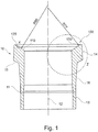
- Figure 1 shows a cross section through the end of a pipeline.
- the cross-section shown can be the end of a straight or curved pipe or a single connection of a T-piece, a Y-piece, a 4-way cross, a 6-way cross or another component known per se for the construction of pipeline networks.
- the pipeline 10 has a longitudinal section 13 which has an essentially constant wall thickness and a parallel outer contour.
- the longitudinal section 13 either serves to transport a fluid flowing in the interior of the pipeline 10 in a straight line or provides the connection of the in Figure 1 illustrated end of the pipeline to one of the pipeline elements described above.
- the first longitudinal section 13 merges with a second longitudinal section 16 into the socket 100.
- the inner wall and / or the outer wall of the second longitudinal section 16 can be inclined outwards by a few degrees with respect to the first longitudinal section 13. This results in an expansion of the pipe cross-section.
- the expansion can be about 1 ° to about 5 ° on the inside of the pipeline.
- the longitudinal section 16 can experience a greater widening of about 3 ° to about 10 °, so that the wall thickness of the second longitudinal section 16 is greater than the wall thickness of the first longitudinal section 13. In this way, the mechanical stability of the Pan 100 can be enlarged.
- a third longitudinal section 14 can adjoin the second longitudinal section 16.
- the third longitudinal section 14 can have a further enlarged outer diameter than the second longitudinal section 16, so that an outer contact surface 15 is formed between the second longitudinal section 16 and the third longitudinal section 14.
- a mechanical fastening element can act on the outer contact surface 15, so that an axial prestress can be exerted on the pipe connection.
- the outer contact surface 15 can include an angle of inclination of less than 90 ° with respect to the longitudinal axis 12 of the pipeline, so that the prestress applied via the outer contact surface 15 exerts an axial and a radial component in the direction of the longitudinal axis 12 on the pipeline 10.
- the outer contact surface 15 can be curved.
- a socket 100 is formed as part of a connection system.
- the socket 100 serves to receive a ball with a complementary outer shape, which is molded onto a second pipeline, not shown.
- the pan 100 has an inner sealing surface 110 and an outer sealing surface 120. Both sealing surfaces are inclined inwards, i.e. in the direction of the longitudinal axis 12 of the pipeline 10. The inclination is approximately 68 to approximately 78 °.
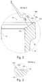
- the inner sealing surface 110 and the outer sealing surface 120 are not designed to be planar in the embodiment shown. Rather, the inner sealing surface 110 has a curvature of approximately 80 mm. The outer sealing surface 120 has a smaller one Curvature of about 77 mm.
- a step 130 is formed between the inner sealing surface 110 and the outer sealing surface 120. The step 130 brings about increased mechanical stability of the pan 100. Furthermore, the step 130 prevents a sealing element inserted into the pan 100 from slipping, so that the assembly of a pipe connection between two pipelines 10 is facilitated.
- Level 130 training is in Figure 3 shown enlarged again.
- Figure 3 shows a section from the third longitudinal section 14 of the pipeline 10 in the area of the inner sealing surface 110 and the outer sealing surface 120.
- the inner and outer sealing surfaces 110 and 120 are inclined in the direction of the longitudinal axis 12 of the pipeline 10, as described above.
- the step 130 is designed to be almost flat, ie at right angles to the longitudinal axis 12.
- the step 130 can be offset inwardly from the end face 101 of the pan 100 by about 2 mm to about 6 mm.
- a circumferential edge 131 is formed at the transition from the step 130 to the inner sealing surface 110.
- the edge 131 Under the action of an axial prestressing force, the edge 131 generates a local stress peak in the elastic sealing element, so that the latter is held in a form-fitting manner on the sealing surfaces 110 and 120. Furthermore, a reliable seal against gaseous fluids is achieved by the stress peak at the edge 131.
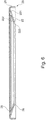
- Figure 6 shows a sealing element, which in connection with the in the Figures 1 to 3 shown pipeline can be used.
- the sealing element according to Figure 6 has a toroidal basic shape. The sealing element can thus be inserted into the pan 110 without affecting the free cross section of the pipeline 10 is hindered by the presence of the sealing element 20.
- the cross section of the sealing element has a first contact surface 21 and a second contact surface 22.
- the second contact surface 22 has an underside 221 and an upper side 222.
- the underside 221 is provided to be in contact with the inner sealing surface 110 and the outer sealing surface 120 of the pan 100 of a pipeline.
- the upper side 222 of the second contact surface 22 is accordingly in contact with a ball 160 which is molded onto a second pipeline 10.
- a raised partial surface 25 is formed on the upper side 222 of the second contact surface 22.
- the raised partial surface 25 can have a width of approximately 1 mm to approximately 5 mm.
- the partial surface 25 can be raised about 0.5 to about 1.5 mm with respect to the top side 222 of the second contact surface 22.
- the inner edge of the partial surface 25 can be arranged approximately 3 mm to approximately 10 mm away from the inner edge of the second contact surface 22.
- the raised partial surface 25 is provided circumferentially in the entire cross section of the sealing element 20.
- a raised partial surface 26 is formed on the underside 221 of the second contact surface 22.
- the raised partial surface 26 can directly adjoin the inner edge 223 of the second contact surface 22.
- the partial surface 26 can have a width of approximately 1 mm to approximately 5 mm and in some embodiments 0.2 to 1 mm above the level of the underside 221 of the second contact surface protrude.
- the first contact surface 21 is provided to lie against the outside of the third longitudinal section 14, so that the sealing element 20 is prevented from slipping in the pan 100. In this way, a simple centering of the sealing element 20 and a quick assembly of the pipe connection is possible.
- the first contact surface 21 and the second contact surface 22 enclose an angle of approximately 68 to approximately 78 °.
- the angle can be adapted to the mean angle of inclination of the pan 100, so that a stress-free installation of the sealing element on the pipeline 10 is made possible.
- the sealing element is made entirely of an elastic material, the angle enclosed by the first contact surface 21 and the second contact surface 22 can be variable, so that the sealing element 20 can also be used universally for known flange connections.
- the sealing element can be produced in one piece, for example by compression molding.
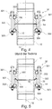
- a known pipe connection shows Figure 4 .
- the pipe connection according to Figure 4 connects two pipes 10 to one another.
- the pipelines 10 Towards their end, the pipelines 10 have a longitudinal section 14 with a larger outer diameter, so that an outer contact surface 15 is formed between the pipeline 10 and the longitudinal section 14.
- the end face of the longitudinal section 14 forms a flange 150 which runs approximately at right angles to the longitudinal axis 12 of the pipeline 10.
- the end face of the longitudinal section 14 forming the flange 150 can be planar or profiled.
- a sealing element is placed between two pipelines 10 introduced, which is compressed by applying an axial prestressing force and in this way seals the pipe connection in a fluid-tight manner.
- the sealing element 20 according to Figure 6 can also be used universally on a known pipe connection.
- the first contact surface 21 rests against the outside of the longitudinal section 14. Due to the elastic connection of the first contact surface 21 and the second contact surface 22 of the sealing element 20, this adapts to the angle of the flange 150, so that the sealing element 20 serves to seal the pipe connection in a manner known per se when subjected to an axial prestressing force.
- a first clamp 301 and a second clamp 302 are provided, each of which engages a contact surface 15 of the pipelines 10.
- an optional elastic element 303 and 304 can be used, which mediates the contact between the contact surface and the clamp.
- the elastic elements 303 and 304 can, for example, have the shape of a hose or a round cord and be made of an elastic plastic material such as EPDM, PTFE, FPM or other materials known per se.
- the clamps 301 and 302 are used to transmit an axial prestressing force to the pipelines 10.
- screws 322 are available, which are distributed along the circumference of the clamps 301 and connected to the clamps 301 and 302 by means of through bores.
- each of the screws 322 is provided with a nut 323, so that the Distance between the clamps 301 and 302 can be varied.
- spring elements 321 can be provided, which define and limit the axial pretensioning force.
- FIG. 5 shows a pipe connection proposed according to the invention.
- a pipeline 10 is shown, which has already been based on the Figures 1 to 3 was explained in more detail.
- the pipe 10 ends at the end in a pan 100 which is inclined in the direction of the interior of the pipe 10.
- the end of the second pipeline 17 ends in the ball 160, which has the same radius as the inner sealing surface 110, that is to say about 80 mm.
- the sealing element 20, as in Figure 6 shown, are plugged onto the pipeline 10 so that the first contact surface 21 rests on the outside of the third longitudinal section 14 and the second contact surface 22 rests on the sealing surfaces 110 and 120 of the pan 100.
- the ball 160 is then inserted into the socket 100, so that the sealing surfaces of the ball 160 bear against the upper side 222 of the second contact surface 22.
- An axial pretensioning force which is applied via two clamps 301 and 302, is used for the final mechanical fixation of the pipe connection and for sealing.
- the clamps are in engagement with the pipelines 10 and 17 via elastic elements 303 and 304, as already shown with reference to FIG Figure 4 described.
- screw connections 322 and 323 which engage clamps 301 and 302 via optional spring elements 321, are used to generate the axial pretensioning force.
- a slight misalignment can be compensated for by the convex shape of the ball 160 and the concave shape of the socket 100, so that the pipe connection remains tight even in the event of a tilted assembly and the pipes 10 and 17 are not damaged by the axial pretensioning force. This facilitates the assembly process so that assembly can be carried out quickly and reliably.
Landscapes
- Engineering & Computer Science (AREA)
- General Engineering & Computer Science (AREA)
- Mechanical Engineering (AREA)
- Joints Allowing Movement (AREA)
Description
- Die Erfindung betrifft eine Rohrverbindung zum Verbinden von zwei Rohrleitungen, wobei ein Rohrende einen Flanschteil mit einer kugelig-konvexen Dichtfläche aufweist und ein anderes Rohrende einen Flanschteil mit einer Pfanne aufweist, wobei zwischen der kugelig-konvexen Dichtfläche und der Pfanne ein ringförmiges Dichtelement angeordnet ist. Rohrleitungen und Dichtelemente der eingangs genannten Art können beispielsweise in der chemischen Verfahrenstechnik und/oder in der Pharmaindustrie zum Transport gasförmiger oder flüssiger Medien eingesetzt werden.
- Aus der Praxis sind Rohrleitungen bekannt, welche an zumindest einem Ende einen Dichtflansch aufweisen, so dass eine Mehrzahl von Rohrleitungen durch zugeordnete Verbindungselemente zusammengefügt werden können. Um die Dichtigkeit der Verbindungsstelle zu gewährleisten, kann ein Dichtelement aus einem elastischen Material zwischen die Dichtflansche der Rohrleitungen eingelegt werden.
- Aus der
DE 31 16 558 A1 ist eine Verbindung von Rohrleitungen oder Rohranschlüssen bekannt. Die Rohrleitungen bestehen insbesondere aus Glas und weisen jeweils Flansche auf, zwischen denen eine Dichtung angeordnet ist. Die Stirnfläche einer der beiden Flansche weist eine zur Mittelachse des Flansches konzentrische Ringnut auf,in welche ein damit korrespondierender, mindestens einseitig aus der Dichtung vorstehender Wulst eingreift. - Die bekannten Rohrverbindungen weisen jedoch den Nachteil auf, dass das Dichtungselement aus der Trennstelle herausrutschen kann, so dass Leckagen entstehen. Dadurch wird der Montageaufwand vergrößert. Weiterhin können bei Betrieb der die Rohrleitungen enthaltenden Anlage flüssige oder gasförmige toxische Medien austreten und eine Gefahr für die Benutzer der Anlage darstellen.
- Der Erfindung liegt daher die Aufgabe zugrunde, eine Rohrverbindung zu schaffen, welche einfach und zuverlässig montierbar ist und einen sicheren Betrieb ermöglicht.
- Die Aufgabe wird erfindungsgemäß durch eine Rohrverbindung gemäß Anspruch 1 gelöst.
- Erfindungsgemäß wird vorgeschlagen, dass zwei Rohrleitungen mit einer Kugel/Pfanne-Verbindung fluiddicht miteinander verbunden werden. Die Pfanne weist dabei eine Dichtfläche auf, welche nach innen geneigt ist, so dass die Kugel darin aufgenommen werden kann. Erfindungsgemäß wurde nun erkannt, dass die Zuverlässigkeit der Abdichtung erhöht werden kann, wenn die Dichtfläche der Pfanne in Umfangsrichtung in eine innere Dichtfläche und eine äußere Dichtfläche unterteilt ist. An der Grenzlinie zwischen der inneren und der äußeren Dichtfläche ist eine Stufe ausgebildet, welche formschlüssig mit dem Dichtelement zusammenwirken kann und dieses somit am Herausrutschen hindert. In den Ausführungsformen der Erfindung bewirkt die Stufe weiterhin eine mechanische Verstärkung bzw. Stabilisierung der Pfanne.
- Das erfindungsgemäße Dichtelement weist eine toroidale Grundform auf. Dadurch kann das Dichtelement entlang dem Umfang der Pfanne eingelegt werden, ohne den Durchfluss zu behindern. Der Querschnitt weist eine erste Anlagefläche auf, welche außen an der Rohrleitung bzw. der Pfanne anliegt und das Dichtelement zentriert sowie am Verrutschen während der Montage hindert. Die zweite Anlagefläche des Dichtelementes ist dazu vorgesehen, an zumindest einer Dichtfläche der Pfanne anzuliegen, so dass ein dichtender Anschluss zweier Rohrleitungen hergestellt werden kann. Da das Dichtelement aus einem elastischen Material gefertigt ist, kann es sich der Form der zweiteiligen Dichtfläche der Pfanne anpassen, so dass ein Formschluss zwischen der in der Dichtfläche angeordneten Stufe und dem Dichtelement ermöglicht werden kann.
- In einigen Ausführungsformen der Erfindung kann die innere Dichtfläche der Pfanne einen Krümmungsradius von etwa 70 mm bis etwa 90 mm aufweisen. In einigen Ausführungsformen der Erfindung kann der Krümmungsradius der inneren Dichtfläche 80 mm betragen. Durch eine solche Krümmung der Dichtfläche wird eine zur Kugel der zweiten Rohrleitung komplementäre Kontur der Dichtfläche geschaffen, so dass die Rohrleitungen auch dann dichtend miteinander verbunden werden können, wenn diese leicht verkippt zueinander eingebaut werden. Auf diese Weise wird die Montage erleichtert und die Zuverlässigkeit erhöht.
- Gemäß der Erfindung weist die äußere Dichtfläche einen geringeren Krümmungsradius auf als die innere Dichtfläche. In einigen Ausführungsformen der Erfindung kann der Krümmungsradius der inneren Dichtfläche etwa 77 mm betragen. Durch diese Geometrie entsteht ein sichelförmiger Spalt, der das Herausrutschen der Dichtung verhindert.
- In einem Längsabschnitt, welcher die Pfanne aufnimmt bzw. die Außenkontur der Pfanne bildet, kann in einigen Ausführungsformen der vorgeschlagenen Rohrleitung eine äußere Anlagefläche ausgebildet sein, an welche eine Schelle anlegbar ist. Mittels einer solchen außen anliegenden Schelle kann durch Verschrauben oder Verspannen eine kraftschlüssige Verbindung zweier Rohrleitungen hergestellt und/oder eine axiale Vorspannung auf die Verbindungsstelle zweier Rohrleitungen aufgebracht werden. Die axiale Vorspannung kann einerseits die Kugel in die Pfanne drücken und dabei ein Dichtelement komprimieren, so dass eine fluiddichte Verbindung der Rohrenden erhalten wird. Darüber hinaus kann die mechanische Befestigung dazu dienen, die beiden Rohrenden fest miteinander zu verbinden und die mechanische Stabilität der die Rohrleitungen enthaltenden Apparatur sicherstellen.
- In einigen Ausführungsformen der Erfindung kann die mittlere Neigung der inneren Dichtfläche und/oder der äußeren Dichtfläche gegen die Längsachse der Rohrleitung etwa 68° bis etwa 78° betragen. Unter der mittleren Neigung einer gekrümmten Dichtfläche wird dabei die mittlere Neigung der Tangenten an die Oberfläche der Dichtfläche verstanden. Der angegebene Winkelbereich erlaubt eine dichtende Verbindung mit geringer axialer Vorspannung. Weiterhin bleibt die Dichtwirkung auch dann erhalten, wenn die beiden aneinander grenzenden Rohrleitungen um einige Grad verkippt sind.
- In einigen Ausführungen können zumindest die innere Dichtfläche und/oder die äußere Dichtfläche feuerpoliert sein. Unter einer Feuerpolitur wird für die Zwecke dieser Beschreibung verstanden, dass die Oberfläche bzw. eine oberflächennahe Schicht bis zum Schmelzpunkt erhitzt wird, so dass durch das Aufweichen der Glasoberfläche die bis dahin raue Oberflächenstruktur glatt verschmolzen werden kann und vorhandene Kanten abgerundet werden können. Hierzu kann die Rohrleitung oder die Pfanne in einigen Ausführungsformen der Erfindung ein Glas oder eine Glaskeramik enthalten oder daraus bestehen.
- Das in der Erfindung zur Abdichtung verwendete Dichtelement kann einen Gummi enthalten oder daraus bestehen. In einigen Ausführungsformen der Erfindung kann das Dichtelement Gummi Ethylen-Propylen-Dien-Kautschuk oder Fluorkautschuk enthalten. Dabei kann der Fluorkautschuk ausgewählt sein aus Polymeren, welche als gemeinsames Merkmal Vinyliden(di)fluorid als eines ihrer Monomere besitzen. In anderen Ausführungsformen der Erfindung kann das Dichtelement Polytetrafluorethylen enthalten oder daraus bestehen. Dadurch können die chemische Beständigkeit und die Einsatztemperatur erhöht sein. Die Einsatztemperatur kann mehr als 400 K oder mehr als 450 K oder mehr als 500 K betragen.
- Gemäß der Erfindung ist auf der Oberseite der zweiten Anlagefläche eine erhabene Teilfläche ausgebildet. Diese ermöglicht eine vergrößere mechanische Stabilität des Dichtelementes sowie eine zuverlässigere Abdichtung.
- Gemäß der Erfindung ist auf der Unterseite der zweiten Anlagefläche eine erhabene Teilfläche ausgebildet Gemäß der Erfindung ist somit sowohl auf der Ober- als auch auf der Unterseite der zweiten Anlagefläche des Dichtelementes eine erhabene Teilfläche ausgebildet. Hierdurch kann die Dichtwirkung beiderseits der zweiten Anlagefläche erhöht und das Verrutschen des Dichtelementes auf der Dichtfläche weiter verhindert werden, so dass die Verbindung zuverlässig auch bei geringer axialer Vorspannung hergestellt werden kann.
- In einigen Ausführungsformen der Erfindung können die erste Anlagefläche und die zweite Anlagefläche des Dichtelementes einen Winkel von etwa 68° bis etwa 78° einschließen. Somit kann das Dichtelement komplementär zur Pfanne einer Rohrleitung geformt sein, so dass das Dichtelement zur Montage spannungsfrei in die Pfanne der Rohrleitung eingelegt werden kann. Auf diese Weise wird ein Herausspringen des Dichtelementes aus der Pfanne während der Montage vermieden und die Montage der Rohrverbindung wird vereinfacht.
- Nachfolgend soll die Erfindung anhand von Figuren ohne Beschränkung des allgemeinen Erfindungsgedankens näher erläutert werden. Dabei zeigt:
- Figur 1
- einen Querschnitt durch eine erfindungsgemäße Rohrleitung,
- Figur 2
- eine vergrößerte Darstellung der Pfanne,
- Figur 3
- die vergrößerte Darstellung der zwischen der ersten und zweiten Dichtfläche angeordneten Stufe,
- Figur 4
- eine bekannte Rohrverbindung,
- Figur 5
- eine erfindungsgemäße Rohrverbindung,
- Figur 6
- einen Querschnitt durch ein erfindungsgemäßes Dichtelement.
-
Figur 1 zeigt einen Querschnitt durch das Ende einer Rohrleitung. Bei dem inFigur 1 gezeigten Querschnitt kann es sich um das Ende einer geraden oder gekrümmten Rohrleitung handeln oder um einen einzelnen Anschluss eines T-Stückes, eines Y-Stückes, eines 4-fach-Kreuzes, eines 6-fach-Kreuzes oder eines anderen, an sich bekannten Bauteiles zur Konstruktion von Leitungsnetzen. - Die Rohrleitung 10 weist einen Längsabschnitt 13 auf, welcher eine im Wesentlichen konstante Wandstärke und eine parallele Außenkontur aufweist. Der Längsabschnitt 13 dient entweder dem geradlinigen Transport eines im Inneren der Rohrleitung 10 strömenden Fluids oder vermittelt den Anschluss des in
Figur 1 dargestellten Endes der Rohrleitung an eines der vorstehend beschriebenen Rohrleitungselemente. - Der erste Längsabschnitt 13 geht mit einem zweiten Längsabschnitt 16 in die Pfanne 100 über. Die Innenwandung und/oder die Außenwandung des zweiten Längsabschnittes 16 kann gegenüber dem ersten Längsabschnitt 13 um wenige Grad nach außen geneigt sein. Dadurch ergibt sich eine Aufweitung des Rohrquerschnittes. Die Aufweitung kann an der Innenseite der Rohrleitung etwa 1° bis etwa 5° betragen. An der Außenseite 11 der Rohrleitung 10 kann der Längsabschnitt 16 eine stärkere Aufweitung von etwa 3° bis etwa 10° erfahren, so dass die Wandstärke des zweiten Längsabschnittes 16 größer ist als die Wandstärke des ersten Längsabschnittes 13. Auf diese Weise kann die mechanische Stabilität der Pfanne 100 vergrößert werden.
- An den zweiten Längsabschnitt 16 kann sich ein dritter Längsabschnitt 14 anschließen. Der dritte Längsabschnitt 14 kann einen gegenüber dem zweiten Längsabschnitt 16 weiter vergrößerten Außendurchmesser aufweisen, so dass sich zwischen dem zweiten Längsabschnitt 16 und dem dritten Längsabschnitt 14 eine äußere Anlagefläche 15 ausbildet. Über die äußere Anlagefläche 15 kann ein mechanisches Befestigungselement angreifen, so dass eine axiale Vorspannung auf die Rohrverbindung ausgeübt werden kann. Die äußere Anlagefläche 15 kann gegenüber der Längsachse 12 der Rohrleitung einen Neigungswinkel von weniger als 90° einschließen, so dass die über die äußere Anlagefläche 15 eingebrachte Vorspannung eine axiale und eine radiale Komponente in Richtung auf die Längsachse 12 auf die Rohrleitung 10 ausübt. In einigen Ausführungsformen der Erfindung kann die äußere Anlagefläche 15 gekrümmt sein.
- Am Ende des dritten Längsabschnittes 14 ist eine Pfanne 100 als Teil eines Verbindungssystems ausgebildet. Die Pfanne 100 dient zur Aufnahme einer Kugel mit komplementärer Außenform, welche an einer nicht dargestellten zweiten Rohrleitung angeformt ist.
- Die Pfanne 100 weist eine innere Dichtfläche 110 sowie eine äußere Dichtfläche 120 auf. Beide Dichtflächen sind nach innen geneigt, d.h. in Richtung auf die Längsachse 12 der Rohrleitung 10. Die Neigung beträgt etwa 68 bis etwa 78°.
- Wie in der vergrößerten Darstellung der
Figur 2 ersichtlich ist, sind die innere Dichtfläche 110 und die äußere Dichtfläche 120 in der dargestellten Ausführungsform nicht eben ausgeführt. Vielmehr weist die innere Dichtfläche 110 eine Krümmung von etwa 80 mm auf. Die äußere Dichtfläche 120 weist eine geringere Krümmung von etwa 77 mm auf. Zwischen der inneren Dichtfläche 110 und der äußeren Dichtfläche 120 ist eine Stufe 130 ausgebildet. Die Stufe 130 bewirkt eine vergrößerte mechanische Stabilität der Pfanne 100. Weiterhin verhindert die Stufe 130 das Verrutschen eines in die Pfanne 100 eingelegten Dichtelementes, so dass die Montage einer Rohrverbindung zweier Rohrleitungen 10 erleichtert ist. - Die Ausbildung der Stufe 130 ist in
Figur 3 nochmals vergrößert dargestellt.Figur 3 zeigt einen Ausschnitt aus dem dritten Längsabschnitt 14 der Rohrleitung 10 im Bereich der inneren Dichtfläche 110 und der äußeren Dichtfläche 120. InFigur 3 ist ersichtlich, dass die innere und die äußere Dichtfläche 110 und 120 in Richtung der Längsachse 12 der Rohrleitung 10 geneigt sind, wie vorstehend beschrieben. Die Stufe 130 ist demgegenüber nahezu eben ausgeführt, d.h. rechtwinklig zur Längsachse 12. Die Stufe 130 kann in einigen Ausführungsformen der Erfindung etwa 2 mm bis etwa 6 mm von der Stirnseite 101 der Pfanne 100 nach innen versetzt angeordnet sein. Am Übergang der Stufe 130 in die innere Dichtfläche 110 bildet sich eine umlaufende Kante 131 aus. Die Kante 131 erzeugt unter der Einwirkung einer axialen Vorspannkraft eine lokale Spannungsspitze im elastischen Dichtelement, so dass dieses formschlüssig auf den Dichtflächen 110 und 120 gehalten wird. Weiterhin wird durch die Spannungsspitze an der Kante 131 eine zuverlässige Abdichtung auch gegen gasförmige Fluide erreicht. -
Figur 6 zeigt ein Dichtelement, welches in Verbindung mit der in denFiguren 1 bis 3 dargestellten Rohrleitung verwendbar ist. Das Dichtelement gemäßFigur 6 weist eine toroidale Grundform auf. Somit kann das Dichtelement in die Pfanne 110 eingelegt werden, ohne dass der freie Querschnitt der Rohrleitung 10 durch die Anwesenheit des Dichtelementes 20 behindert wird. - Der Querschnitt des Dichtelementes weist eine erste Anlagefläche 21 und eine zweite Anlagefläche 22 auf. Die zweite Anlagefläche 22 weist eine Unterseite 221 sowie eine Oberseite 222 auf. Die Unterseite 221 ist dazu vorgesehen, mit der inneren Dichtfläche 110 und der äußeren Dichtfläche 120 der Pfanne 100 einer Rohrleitung in Kontakt zu stehen. Die Oberseite 222 der zweiten Anlagefläche 22 steht dementsprechend mit einer Kugel 160 in Kontakt, welche an einer zweiten Rohrleitung 10 angeformt ist.
- Zur mechanischen Stabilisierung und/oder zur verbesserten Abdichtung der Rohrverbindung ist an der Oberseite 222 der zweiten Anlagefläche 22 eine erhabene Teilfläche 25 ausgebildet. Die erhabene Teilfläche 25 kann eine Breite von etwa 1 mm bis etwa 5 mm aufweisen. Die Teilfläche 25 kann gegenüber der Oberseite 222 der zweiten Anlagefläche 22 etwa 0,5 bis etwa 1,5 mm erhaben sein. Die Innenkante der Teilfläche 25 kann etwa 3 mm bis etwa 10 mm von der Innenkante der zweiten Anlagefläche 22 entfernt angeordnet sein. Die erhabene Teilfläche 25 ist umlaufend im gesamten Querschnitt des Dichtelementes 20 vorgesehen.
- In vergleichbarer Weise ist auf der Unterseite 221 der zweiten Anlagefläche 22 eine erhabene Teilfläche 26 ausgebildet. Die erhabene Teilfläche 26 kann in einigen Ausführungsformen unmittelbar an die Innenkante 223 der zweiten Anlagefläche 22 angrenzen. Die Teilfläche 26 kann eine Breite von etwa 1 mm bis etwa 5 mm aufweisen und in einigen Ausführungsformen 0,2 bis 1 mm über das Niveau der Unterseite 221 der zweiten Anlagefläche hinausragen.
- Die erste Anlagefläche 21 ist dazu vorgesehen, an der Außenseite des dritten Längsabschnittes 14 anzuliegen, so dass das Dichtelement 20 daran gehindert wird, in der Pfanne 100 zu verrutschen. Auf diese Weise ist eine einfache Zentrierung des Dichtelementes 20 und eine rasche Montage der Rohrverbindung möglich.
- In einigen Ausführungsformen der Erfindung schließen die erste Anlagefläche 21 und die zweite Anlagefläche 22 einen Winkel von etwa 68 bis etwa 78° ein. Der Winkel kann an den mittleren Neigungswinkel der Pfanne 100 angepasst sein, so dass eine spannungsfreie Montage des Dichtelementes auf der Rohrleitung 10 ermöglicht wird. Da das Dichtelement vollständig aus einem elastischen Material gefertigt ist, kann der von der ersten Anlagefläche 21 und der zweiten Anlagefläche 22 eingeschlossene Winkel variabel sein, so dass das Dichtelement 20 universell auch für bereits bekannte Flanschverbindungen einsetzbar ist. Das Dichtelement kann in einigen Ausführungsformen einstückig hergestellt sein, beispielsweise durch Formpressen.
- Eine bekannte Rohrverbindung zeigt
Figur 4 . Die Rohrverbindung gemäßFigur 4 verbindet zwei Rohrleitungen 10 miteinander. Die Rohrleitungen 10 weisen zu ihrem Ende hin einen Längsabschnitt 14 mit größerem Außendurchmesser auf, so dass sich zwischen der Rohrleitung 10 und dem Längsabschnitt 14 eine äußere Anlagefläche 15 ausbildet. Die Stirnseite des Längsabschnittes 14 bildet einen Flansch 150, welcher in etwa rechtwinklig zur Längsachse 12 der Rohrleitung 10 verläuft. Die den Flansch 150 bildende Stirnseite des Längsabschnittes 14 kann plan oder profiliert sein. Zwischen zwei Rohrleitungen 10 wird ein Dichtelement eingeführt, welches durch Beaufschlagen mit einer axialen Vorspannkraft komprimiert wird und auf diese Weise die Rohrverbindung fluiddicht abdichtet. Das Dichtelement 20 gemäßFigur 6 kann dabei universell auch an einer bekannten Rohrverbindung eingesetzt werden. Dabei liegt die erste Anlagefläche 21 an der Außenseite des Längsabschnittes 14 an. Aufgrund der elastischen Verbindung der ersten Anlagefläche 21 und der zweiten Anlagefläche 22 des Dichtelementes 20 passt sich diese an den Winkel des Flansches 150 an, so dass das Dichtelement 20 bei Beaufschlagen mit einer axialen Vorspannkraft in an sich bekannter Weise zur Abdichtung der Rohrverbindung dient. - Zum Erzeugen einer axialen Vorspannkraft ist eine erste Schelle 301 und eine zweite Schelle 302 vorgesehen, welche jeweils an einer Anlagefläche 15 der Rohrleitungen 10 angreifen. Zur Vermeidung von Spannungsspitzen, welche zum Bruch einer Rohrleitung 10 führen könnten, kann ein optionales elastisches Element 303 und 304 eingesetzt werden, welches den Kontakt zwischen der Anlagefläche und der Schelle vermittelt. Die elastischen Elemente 303 und 304 können beispielsweise die Form eines Schlauches oder einer Rundschnur aufweisen und aus einem elastischen Kunststoffmaterial gefertigt sein, wie beispielsweise EPDM, PTFE, FPM oder andere, an sich bekannte Materialien.
- Die Schellen 301 und 302 dienen zum Übertragen einer axialen Vorspannkraft auf die Rohrleitungen 10. Zum Erzeugen dieser axialen Vorspannkraft stehen Schrauben 322 zur Verfügung, welche entlang des Umfangs der Schellen 301 verteilt und mittels Durchgangsbohrungen mit den Schellen 301 und 302 verbunden sind. Zum Erzeugen der Vorspannkraft ist jede der Schrauben 322 mit einer Mutter 323 versehen, so dass der Abstand zwischen den Schellen 301 und 302 variierbar ist. Fallweise können in einigen Ausführungsformen der Erfindung Federelemente 321 vorgesehen sein, welche die axiale Vorspannkraft definieren und begrenzen.
-
Figur 5 zeigt eine erfindungsgemäß vorgeschlagene Rohrverbindung. Im unteren Bildteil ist eine Rohrleitung 10 dargestellt, welche bereits anhand derFiguren 1 bis 3 näher erläutert wurde. Die Rohrleitung 10 läuft am Ende in eine Pfanne 100 aus, welche in Richtung des Innenraumes der Rohrleitung 10 geneigt ist. Die zweite Rohrleitung 17 läuft an ihrem Ende in der Kugel 160 aus, die den gleichen Radius wie die innere Dichtfläche 110, also etwa 80 mm, hat. - Zur Montage der Rohrverbindung kann das Dichtelement 20, wie in
Figur 6 dargestellt, auf die Rohrleitung 10 aufgesteckt werden, so dass die erste Anlagefläche 21 an der Außenseite des dritten Längsabschnittes 14 anliegt und die zweite Anlagefläche 22 an den Dichtflächen 110 und 120 der Pfanne 100 anliegt. - Sodann wird die Kugel 160 in die Pfanne 100 eingeführt, so dass die Dichtflächen der Kugel 160 an der Oberseite 222 der zweiten Anlagefläche 22 anliegen. Zur endgültigen mechanischen Fixierung der Rohrverbindung und zum Abdichten dient eine axiale Vorspannkraft, welche über zwei Schellen 301 und 302 aufgebracht wird. Die Schellen stehen über elastische Elemente 303 und 304 mit den Rohrleitungen 10 und 17 in Eingriff, wie bereits anhand von
Figur 4 beschrieben. Zum Erzeugen der axialen Vorspannkraft dienen wiederum Schraubverbindungen 322 und 323, welche über optionale Federelemente 321 an den Schellen 301 und 302 angreifen. - Durch die konvexe Form der Kugel 160 und die konkave Form der Pfanne 100 kann eine leichte Fehlausrichtung ausgeglichen werden, so dass die Rohrverbindung auch bei einer verkippten Montage noch dicht bleibt und die Rohrleitungen 10 und 17 durch die axiale Vorspannkraft nicht beschädigt werden. Dadurch wird der Montagevorgang erleichtert, so dass die Montage schnell und zuverlässig vorgenommen werden kann.
Claims (10)
- Rohrverbindung zum Verbinden von zwei Rohrleitungen (10), wobei die Rohrverbindung ein Rohrende mit einem Flanschteil mit einer kugelig-konvexen Dichtfläche und ein anderes Rohrende mit einem Flanschteil mit einer Pfanne (100) aufweist, wobei die Pfanne (100) eine innere, nach innen in Richtung auf eine Längsachse (12) geneigte Dichtfläche (110), eine äußere, nach innen in Richtung auf die Längsachse (12) geneigte Dichtfläche (120), eine Stufe (130) zwischen der äußeren und der inneren Dichtfläche (120, 110) und eine umlaufende Kante (131) am Übergang der Stufe (130) in die innere Dichtfläche aufweist, wobei zwischen der kugelig-konvexen Dichtfläche und der Pfanne (100) ein aus einem elastischen Material bestehendes, ringförmiges Dichtelement (20) angeordnet und durch eine auf die Rohrenden einwirkende axiale Vorspannkraft komprimiert ist, wobei das Dichtelement (20) mit einer Oberseite (222) an der kugelig-konvexen Dichtfläche und mit einer Unterseite (221) an der äußeren und der inneren Dichtfläche (120, 110) und der umlaufenden Kante (131) anliegt, wobei eine erhabene Teilfläche (25, 26) jeweils an der Oberseite (222) und an der Unterseite (221) des Dichtelementes (20) ausgebildet ist und die innere und die äußere Dichtfläche (110, 120) jeweils konkav gekrümmt sind, wobei die kugelig-konvexe Dichtfläche den gleichen Radius wie die innere Dichtfläche (110) hat,
dadurch gekennzeichnet, dass
die Stufe (130) eben und rechtwinklig zu der Längsachse (12) ist, die Kante (130) eine lokale Spannungsspitze in dem Dichtelement (20) erzeugt und die äußere Dichtfläche (120) einen geringeren Krümmungsradius als die innere Dichtfläche (110) hat, so dass zwischen der äußeren Dichtfläche (120) und der kugelig-konvexen Dichtfläche ein sichelförmiger Spaltausgebildet ist, der ein Herausrutschen des Dichtelementes (20) verhindert. - Rohrverbindung nach Anspruch 1, dadurch gekennzeichnet, dass die innere Dichtfläche (110) einen Krümmungsradius von etwa 70 mm bis etwa 90 mm aufweist.
- Rohrverbindung nach Anspruch 2, dadurch gekennzeichnet, dass die innere Dichtfläche (110) einen Krümmungsradius von etwa 80 mm aufweist.
- Rohrverbindung nach einem der Ansprüche 1 bis 3, dadurch gekennzeichnet, dass die äußere Dichtfläche (120) einen Krümmungsradius von etwa 77 mm aufweist.
- Rohrverbindung nach einem der Ansprüche 1 bis 4, dadurch gekennzeichnet, dass die Außenseite (11) des anderen Rohrendes eine äußere Anlagefläche (15) aufweist, an welche eine Schelle (301, 302) angelegt ist.
- Rohrverbindung nach einem der Ansprüche 1 bis 5, dadurch gekennzeichnet, dass zumindest die innere Dichtfläche (110) und/oder die äußere Dichtfläche (120) feuerpoliert sind.
- Rohrverbindung nach einem der Ansprüche 1 bis 6, dadurch gekennzeichnet, dass die mittlere Neigung der inneren Dichtfläche (110) und/oder der äußeren Dichtfläche (120) gegen die Längsachse (12) der Rohrleitung (10) etwa 68° bis etwa 78° beträgt.
- Rohrverbindung nach einem der vorhergehenden Ansprüche, dadurch gekennzeichnet, dass der Querschnitt des Dichtelements (20) einen ersten Anlageschenkel (21) und einen zweiten Anlageschenkel (22) aufweist, wobei der erste Anlageschenkel (21) an der Außenseite (14) des Flanschteils des anderen Rohrendes anliegt.
- Rohrverbindung nach einem der vorhergehenden Ansprüche, dadurch gekennzeichnet, dass das Dichtelement (20) Polytetrafluorethylen enthält oder daraus besteht.
- Rohrverbindung nach Anspruch 8 oder 9, dadurch gekennzeichnet, dass der erste Anlageschenkel (21) und der zweite Anlageschenkel (22) einen Winkel von etwa 68° bis etwa 78° einschließen.
Applications Claiming Priority (2)
| Application Number | Priority Date | Filing Date | Title |
|---|---|---|---|
| DE102010050720A DE102010050720A1 (de) | 2010-11-08 | 2010-11-08 | Rohrleitung, Dichtelement und Rohrverbindung |
| PCT/EP2011/066243 WO2012062503A1 (de) | 2010-11-08 | 2011-09-19 | Rohrleitung, dichtelement und rohrverbindung |
Publications (2)
| Publication Number | Publication Date |
|---|---|
| EP2638316A1 EP2638316A1 (de) | 2013-09-18 |
| EP2638316B1 true EP2638316B1 (de) | 2021-09-08 |
Family
ID=44651842
Family Applications (1)
| Application Number | Title | Priority Date | Filing Date |
|---|---|---|---|
| EP11757649.6A Active EP2638316B1 (de) | 2010-11-08 | 2011-09-19 | Rohrverbindung |
Country Status (4)
| Country | Link |
|---|---|
| EP (1) | EP2638316B1 (de) |
| CN (1) | CN103201550B (de) |
| DE (1) | DE102010050720A1 (de) |
| WO (1) | WO2012062503A1 (de) |
Families Citing this family (3)
| Publication number | Priority date | Publication date | Assignee | Title |
|---|---|---|---|---|
| CN104121440A (zh) * | 2013-04-27 | 2014-10-29 | 陕西飞机工业(集团)有限公司 | 一种飞机上的高温管路连接结构 |
| CN107002914B (zh) * | 2014-11-28 | 2020-07-10 | 通用电器技术有限公司 | 流体导管元件以及用于形成流体导管元件的方法 |
| DE202017104929U1 (de) * | 2017-08-16 | 2018-11-19 | Rosen Swiss Ag | Verschlussvorrichtung |
Family Cites Families (9)
| Publication number | Priority date | Publication date | Assignee | Title |
|---|---|---|---|---|
| DE8425525U1 (de) * | 1984-12-06 | Struve, Armin, 5090 Leverkusen | Kunststoffdichtring, insbesondere aus Polytetrafluorethylen, für Glasverbindungen | |
| US3147014A (en) * | 1962-07-20 | 1964-09-01 | American Pipe & Constr Co | Foam gasket joint for concrete pipe and method of making same |
| DE2641504A1 (de) * | 1976-09-15 | 1978-03-16 | Sallhofer Hans Dr Phys | Winkelverstellbarer rohrkruemmer |
| DE2655473C3 (de) * | 1976-12-08 | 1979-09-13 | Jenaer Glaswerk Schott & Gen., 6500 Mainz | Auswinkelbare Flanschverbindung für Rohrleitungen |
| DE3116558A1 (de) * | 1981-04-25 | 1982-11-11 | Laborglas Miethke GmbH, 5090 Leverkusen | Verbindung von rohrleitungen oder rohranschluessen, insbesondere aus glas |
| FR2673995B1 (fr) * | 1991-03-15 | 1993-12-03 | Tuyaux Bonna | Tuyau a abouts renforces et son procede de fabrication. |
| EP0692082B1 (de) * | 1994-01-20 | 2000-04-05 | Fritz Schneider | Ringförmige Dichtung und Verfahren zur Herstellung |
| US6834893B2 (en) * | 2001-11-01 | 2004-12-28 | Visteon Global Technologies, Inc. | Peanut fittings for CO2 air conditioning systems |
| DE102007019330A1 (de) * | 2007-04-24 | 2008-10-30 | Reinz-Dichtungs-Gmbh | Dreidimensionale Flachdichtung |
-
2010
- 2010-11-08 DE DE102010050720A patent/DE102010050720A1/de not_active Ceased
-
2011
- 2011-09-19 EP EP11757649.6A patent/EP2638316B1/de active Active
- 2011-09-19 WO PCT/EP2011/066243 patent/WO2012062503A1/de not_active Ceased
- 2011-09-19 CN CN201180053699.2A patent/CN103201550B/zh active Active
Also Published As
| Publication number | Publication date |
|---|---|
| EP2638316A1 (de) | 2013-09-18 |
| CN103201550B (zh) | 2016-03-09 |
| CN103201550A (zh) | 2013-07-10 |
| WO2012062503A1 (de) | 2012-05-18 |
| DE102010050720A1 (de) | 2012-05-10 |
Similar Documents
| Publication | Publication Date | Title |
|---|---|---|
| EP2035736B1 (de) | Muffenverbindung | |
| CH667905A5 (de) | Flanschverbindung fuer faserverstaerkte kunststoffrohrteile. | |
| CH664612A5 (de) | Steckkupplung zum verbinden der enden zweier rohre. | |
| CH665268A5 (de) | Steckkupplung zum verbinden der enden zweier rohre. | |
| EP3679284A1 (de) | Rohrvorrichtung mit stoffschlüssiger verbindung | |
| EP4115107A1 (de) | Rohrverbindung | |
| EP0133459B1 (de) | Dichte und zugfeste Rohrverbindung. | |
| DE60214775T2 (de) | Flanschglied mit einem ersten flanschende, das in einer radialrichtung mit einer konkaven endfläche ausgeführt ist, und einer flanschgliederumfassenden flanschverbindung | |
| DE102010050720A1 (de) | Rohrleitung, Dichtelement und Rohrverbindung | |
| DE202015106969U1 (de) | Anschlusssystem | |
| DE2251082C3 (de) | Zugfeste Verbindung zweier Kanalisationsrohre | |
| DE4005474A1 (de) | Anschlussarmatur fuer sicherheitsrohrleitungen aus thermoplastischen kunststoffen | |
| DE69901563T2 (de) | Anordnungsverfahren zum verbinden einer armatur mit einem rohrelement und ein neuer typ kupplung zur duerchführung des verfahrens | |
| DE102011053208A1 (de) | Verbindungsanordnung für Fluidleitungen mit einer weiteren fluidführenden Komponente | |
| WO1982003440A1 (en) | Sealed coupling of plastic material pipes resisting to thrust forces | |
| DE202013007855U1 (de) | Dichteinrichtung für Rohrverbindungen | |
| DE102004052706A1 (de) | Dichtring für eine Dichtungsanordnung zum Abdichten einer Verbindungsstelle einer Rohrleitung | |
| DE2655473C3 (de) | Auswinkelbare Flanschverbindung für Rohrleitungen | |
| DE4009403C2 (de) | Rohrleitungskupplung | |
| DE202016106901U1 (de) | Rohrverbinder | |
| EP1837575A1 (de) | Anschlussstück für Rohre mit einer quellbaren Dichtung | |
| EP2568206B1 (de) | Verbindungsanordnung | |
| DE10156464B4 (de) | Fitting | |
| DE10252981B4 (de) | Rohrleitungsabstandhalter | |
| EP2463564A2 (de) | Verrohrungssystem und Verfahren zur Herstellung eines Verrohrungssystems |
Legal Events
| Date | Code | Title | Description |
|---|---|---|---|
| PUAI | Public reference made under article 153(3) epc to a published international application that has entered the european phase |
Free format text: ORIGINAL CODE: 0009012 |
|
| 17P | Request for examination filed |
Effective date: 20130508 |
|
| AK | Designated contracting states |
Kind code of ref document: A1 Designated state(s): AL AT BE BG CH CY CZ DE DK EE ES FI FR GB GR HR HU IE IS IT LI LT LU LV MC MK MT NL NO PL PT RO RS SE SI SK SM TR |
|
| DAX | Request for extension of the european patent (deleted) | ||
| STAA | Information on the status of an ep patent application or granted ep patent |
Free format text: STATUS: EXAMINATION IS IN PROGRESS |
|
| 17Q | First examination report despatched |
Effective date: 20171108 |
|
| GRAP | Despatch of communication of intention to grant a patent |
Free format text: ORIGINAL CODE: EPIDOSNIGR1 |
|
| STAA | Information on the status of an ep patent application or granted ep patent |
Free format text: STATUS: GRANT OF PATENT IS INTENDED |
|
| RIC1 | Information provided on ipc code assigned before grant |
Ipc: F16L 27/06 20060101ALI20210412BHEP Ipc: F16L 27/053 20060101ALI20210412BHEP Ipc: F16L 23/22 20060101ALI20210412BHEP Ipc: F16L 23/028 20060101ALI20210412BHEP Ipc: F16L 23/032 20060101AFI20210412BHEP |
|
| INTG | Intention to grant announced |
Effective date: 20210504 |
|
| GRAS | Grant fee paid |
Free format text: ORIGINAL CODE: EPIDOSNIGR3 |
|
| GRAA | (expected) grant |
Free format text: ORIGINAL CODE: 0009210 |
|
| STAA | Information on the status of an ep patent application or granted ep patent |
Free format text: STATUS: THE PATENT HAS BEEN GRANTED |
|
| AK | Designated contracting states |
Kind code of ref document: B1 Designated state(s): AL AT BE BG CH CY CZ DE DK EE ES FI FR GB GR HR HU IE IS IT LI LT LU LV MC MK MT NL NO PL PT RO RS SE SI SK SM TR |
|
| REG | Reference to a national code |
Ref country code: GB Ref legal event code: FG4D Free format text: NOT ENGLISH |
|
| REG | Reference to a national code |
Ref country code: AT Ref legal event code: REF Ref document number: 1428885 Country of ref document: AT Kind code of ref document: T Effective date: 20210915 Ref country code: CH Ref legal event code: EP |
|
| REG | Reference to a national code |
Ref country code: IE Ref legal event code: FG4D Free format text: LANGUAGE OF EP DOCUMENT: GERMAN |
|
| REG | Reference to a national code |
Ref country code: DE Ref legal event code: R096 Ref document number: 502011017226 Country of ref document: DE |
|
| REG | Reference to a national code |
Ref country code: LT Ref legal event code: MG9D |
|
| REG | Reference to a national code |
Ref country code: NL Ref legal event code: MP Effective date: 20210908 |
|
| PG25 | Lapsed in a contracting state [announced via postgrant information from national office to epo] |
Ref country code: HR Free format text: LAPSE BECAUSE OF FAILURE TO SUBMIT A TRANSLATION OF THE DESCRIPTION OR TO PAY THE FEE WITHIN THE PRESCRIBED TIME-LIMIT Effective date: 20210908 Ref country code: SE Free format text: LAPSE BECAUSE OF FAILURE TO SUBMIT A TRANSLATION OF THE DESCRIPTION OR TO PAY THE FEE WITHIN THE PRESCRIBED TIME-LIMIT Effective date: 20210908 Ref country code: NO Free format text: LAPSE BECAUSE OF FAILURE TO SUBMIT A TRANSLATION OF THE DESCRIPTION OR TO PAY THE FEE WITHIN THE PRESCRIBED TIME-LIMIT Effective date: 20211208 Ref country code: RS Free format text: LAPSE BECAUSE OF FAILURE TO SUBMIT A TRANSLATION OF THE DESCRIPTION OR TO PAY THE FEE WITHIN THE PRESCRIBED TIME-LIMIT Effective date: 20210908 Ref country code: FI Free format text: LAPSE BECAUSE OF FAILURE TO SUBMIT A TRANSLATION OF THE DESCRIPTION OR TO PAY THE FEE WITHIN THE PRESCRIBED TIME-LIMIT Effective date: 20210908 Ref country code: ES Free format text: LAPSE BECAUSE OF FAILURE TO SUBMIT A TRANSLATION OF THE DESCRIPTION OR TO PAY THE FEE WITHIN THE PRESCRIBED TIME-LIMIT Effective date: 20210908 Ref country code: LT Free format text: LAPSE BECAUSE OF FAILURE TO SUBMIT A TRANSLATION OF THE DESCRIPTION OR TO PAY THE FEE WITHIN THE PRESCRIBED TIME-LIMIT Effective date: 20210908 Ref country code: BG Free format text: LAPSE BECAUSE OF FAILURE TO SUBMIT A TRANSLATION OF THE DESCRIPTION OR TO PAY THE FEE WITHIN THE PRESCRIBED TIME-LIMIT Effective date: 20211208 |
|
| PG25 | Lapsed in a contracting state [announced via postgrant information from national office to epo] |
Ref country code: LV Free format text: LAPSE BECAUSE OF FAILURE TO SUBMIT A TRANSLATION OF THE DESCRIPTION OR TO PAY THE FEE WITHIN THE PRESCRIBED TIME-LIMIT Effective date: 20210908 Ref country code: GR Free format text: LAPSE BECAUSE OF FAILURE TO SUBMIT A TRANSLATION OF THE DESCRIPTION OR TO PAY THE FEE WITHIN THE PRESCRIBED TIME-LIMIT Effective date: 20211209 |
|
| REG | Reference to a national code |
Ref country code: BE Ref legal event code: MM Effective date: 20210930 |
|
| PG25 | Lapsed in a contracting state [announced via postgrant information from national office to epo] |
Ref country code: IS Free format text: LAPSE BECAUSE OF FAILURE TO SUBMIT A TRANSLATION OF THE DESCRIPTION OR TO PAY THE FEE WITHIN THE PRESCRIBED TIME-LIMIT Effective date: 20220108 Ref country code: SM Free format text: LAPSE BECAUSE OF FAILURE TO SUBMIT A TRANSLATION OF THE DESCRIPTION OR TO PAY THE FEE WITHIN THE PRESCRIBED TIME-LIMIT Effective date: 20210908 Ref country code: SK Free format text: LAPSE BECAUSE OF FAILURE TO SUBMIT A TRANSLATION OF THE DESCRIPTION OR TO PAY THE FEE WITHIN THE PRESCRIBED TIME-LIMIT Effective date: 20210908 Ref country code: RO Free format text: LAPSE BECAUSE OF FAILURE TO SUBMIT A TRANSLATION OF THE DESCRIPTION OR TO PAY THE FEE WITHIN THE PRESCRIBED TIME-LIMIT Effective date: 20210908 Ref country code: PT Free format text: LAPSE BECAUSE OF FAILURE TO SUBMIT A TRANSLATION OF THE DESCRIPTION OR TO PAY THE FEE WITHIN THE PRESCRIBED TIME-LIMIT Effective date: 20220110 Ref country code: PL Free format text: LAPSE BECAUSE OF FAILURE TO SUBMIT A TRANSLATION OF THE DESCRIPTION OR TO PAY THE FEE WITHIN THE PRESCRIBED TIME-LIMIT Effective date: 20210908 Ref country code: NL Free format text: LAPSE BECAUSE OF FAILURE TO SUBMIT A TRANSLATION OF THE DESCRIPTION OR TO PAY THE FEE WITHIN THE PRESCRIBED TIME-LIMIT Effective date: 20210908 Ref country code: EE Free format text: LAPSE BECAUSE OF FAILURE TO SUBMIT A TRANSLATION OF THE DESCRIPTION OR TO PAY THE FEE WITHIN THE PRESCRIBED TIME-LIMIT Effective date: 20210908 Ref country code: AL Free format text: LAPSE BECAUSE OF FAILURE TO SUBMIT A TRANSLATION OF THE DESCRIPTION OR TO PAY THE FEE WITHIN THE PRESCRIBED TIME-LIMIT Effective date: 20210908 |
|
| REG | Reference to a national code |
Ref country code: DE Ref legal event code: R097 Ref document number: 502011017226 Country of ref document: DE |
|
| PG25 | Lapsed in a contracting state [announced via postgrant information from national office to epo] |
Ref country code: MC Free format text: LAPSE BECAUSE OF FAILURE TO SUBMIT A TRANSLATION OF THE DESCRIPTION OR TO PAY THE FEE WITHIN THE PRESCRIBED TIME-LIMIT Effective date: 20210908 |
|
| PLBE | No opposition filed within time limit |
Free format text: ORIGINAL CODE: 0009261 |
|
| STAA | Information on the status of an ep patent application or granted ep patent |
Free format text: STATUS: NO OPPOSITION FILED WITHIN TIME LIMIT |
|
| PG25 | Lapsed in a contracting state [announced via postgrant information from national office to epo] |
Ref country code: LU Free format text: LAPSE BECAUSE OF NON-PAYMENT OF DUE FEES Effective date: 20210919 Ref country code: IE Free format text: LAPSE BECAUSE OF NON-PAYMENT OF DUE FEES Effective date: 20210919 Ref country code: DK Free format text: LAPSE BECAUSE OF FAILURE TO SUBMIT A TRANSLATION OF THE DESCRIPTION OR TO PAY THE FEE WITHIN THE PRESCRIBED TIME-LIMIT Effective date: 20210908 Ref country code: BE Free format text: LAPSE BECAUSE OF NON-PAYMENT OF DUE FEES Effective date: 20210930 |
|
| 26N | No opposition filed |
Effective date: 20220609 |
|
| GBPC | Gb: european patent ceased through non-payment of renewal fee |
Effective date: 20211208 |
|
| PG25 | Lapsed in a contracting state [announced via postgrant information from national office to epo] |
Ref country code: SI Free format text: LAPSE BECAUSE OF FAILURE TO SUBMIT A TRANSLATION OF THE DESCRIPTION OR TO PAY THE FEE WITHIN THE PRESCRIBED TIME-LIMIT Effective date: 20210908 |
|
| PG25 | Lapsed in a contracting state [announced via postgrant information from national office to epo] |
Ref country code: GB Free format text: LAPSE BECAUSE OF NON-PAYMENT OF DUE FEES Effective date: 20211208 |
|
| REG | Reference to a national code |
Ref country code: AT Ref legal event code: MM01 Ref document number: 1428885 Country of ref document: AT Kind code of ref document: T Effective date: 20210919 |
|
| PG25 | Lapsed in a contracting state [announced via postgrant information from national office to epo] |
Ref country code: AT Free format text: LAPSE BECAUSE OF NON-PAYMENT OF DUE FEES Effective date: 20210919 |
|
| PG25 | Lapsed in a contracting state [announced via postgrant information from national office to epo] |
Ref country code: HU Free format text: LAPSE BECAUSE OF FAILURE TO SUBMIT A TRANSLATION OF THE DESCRIPTION OR TO PAY THE FEE WITHIN THE PRESCRIBED TIME-LIMIT; INVALID AB INITIO Effective date: 20110919 Ref country code: CY Free format text: LAPSE BECAUSE OF FAILURE TO SUBMIT A TRANSLATION OF THE DESCRIPTION OR TO PAY THE FEE WITHIN THE PRESCRIBED TIME-LIMIT Effective date: 20210908 |
|
| PG25 | Lapsed in a contracting state [announced via postgrant information from national office to epo] |
Ref country code: MK Free format text: LAPSE BECAUSE OF FAILURE TO SUBMIT A TRANSLATION OF THE DESCRIPTION OR TO PAY THE FEE WITHIN THE PRESCRIBED TIME-LIMIT Effective date: 20210908 |
|
| PG25 | Lapsed in a contracting state [announced via postgrant information from national office to epo] |
Ref country code: MT Free format text: LAPSE BECAUSE OF FAILURE TO SUBMIT A TRANSLATION OF THE DESCRIPTION OR TO PAY THE FEE WITHIN THE PRESCRIBED TIME-LIMIT Effective date: 20210908 |
|
| REG | Reference to a national code |
Ref country code: CH Ref legal event code: U11 Free format text: ST27 STATUS EVENT CODE: U-0-0-U10-U11 (AS PROVIDED BY THE NATIONAL OFFICE) Effective date: 20251001 |
|
| PGFP | Annual fee paid to national office [announced via postgrant information from national office to epo] |
Ref country code: DE Payment date: 20250919 Year of fee payment: 15 |
|
| PGFP | Annual fee paid to national office [announced via postgrant information from national office to epo] |
Ref country code: IT Payment date: 20250924 Year of fee payment: 15 |
|
| PGFP | Annual fee paid to national office [announced via postgrant information from national office to epo] |
Ref country code: FR Payment date: 20250922 Year of fee payment: 15 |
|
| PGFP | Annual fee paid to national office [announced via postgrant information from national office to epo] |
Ref country code: CZ Payment date: 20250910 Year of fee payment: 15 |
|
| PG25 | Lapsed in a contracting state [announced via postgrant information from national office to epo] |
Ref country code: TR Free format text: LAPSE BECAUSE OF FAILURE TO SUBMIT A TRANSLATION OF THE DESCRIPTION OR TO PAY THE FEE WITHIN THE PRESCRIBED TIME-LIMIT Effective date: 20210908 |
|
| PGFP | Annual fee paid to national office [announced via postgrant information from national office to epo] |
Ref country code: CH Payment date: 20251001 Year of fee payment: 15 |
|
| REG | Reference to a national code |
Ref country code: DE Ref legal event code: R081 Ref document number: 502011017226 Country of ref document: DE Owner name: DE DIETRICH GERMANY MAINZ GMBH, DE Free format text: FORMER OWNER: DE DIETRICH PROCESS SYSTEMS GMBH, 55122 MAINZ, DE |
|
| REG | Reference to a national code |
Ref country code: CH Ref legal event code: R18 Free format text: ST27 STATUS EVENT CODE: U-0-0-R10-R18 (AS PROVIDED BY THE NATIONAL OFFICE) Effective date: 20260429 |