EP2637611B1 - Deployment catheter for endoluminal devices - Google Patents
Deployment catheter for endoluminal devices Download PDFInfo
- Publication number
- EP2637611B1 EP2637611B1 EP11785264.0A EP11785264A EP2637611B1 EP 2637611 B1 EP2637611 B1 EP 2637611B1 EP 11785264 A EP11785264 A EP 11785264A EP 2637611 B1 EP2637611 B1 EP 2637611B1
- Authority
- EP
- European Patent Office
- Prior art keywords
- catheter
- outer peripheral
- seam
- peripheral dimension
- set forth
- Prior art date
- Legal status (The legal status is an assumption and is not a legal conclusion. Google has not performed a legal analysis and makes no representation as to the accuracy of the status listed.)
- Active
Links
- 230000002093 peripheral effect Effects 0.000 claims description 33
- 230000008878 coupling Effects 0.000 claims description 20
- 238000010168 coupling process Methods 0.000 claims description 20
- 238000005859 coupling reaction Methods 0.000 claims description 20
- 238000011282 treatment Methods 0.000 claims description 20
- 238000000034 method Methods 0.000 claims description 12
- 230000000452 restraining effect Effects 0.000 claims description 10
- 229920000295 expanded polytetrafluoroethylene Polymers 0.000 claims description 7
- 238000009941 weaving Methods 0.000 claims 1
- -1 polyethylene Polymers 0.000 description 24
- 239000000463 material Substances 0.000 description 15
- 210000005166 vasculature Anatomy 0.000 description 10
- 229920000785 ultra high molecular weight polyethylene Polymers 0.000 description 7
- 230000017531 blood circulation Effects 0.000 description 6
- 239000004699 Ultra-high molecular weight polyethylene Substances 0.000 description 5
- 239000004810 polytetrafluoroethylene Substances 0.000 description 5
- 229920001343 polytetrafluoroethylene Polymers 0.000 description 5
- RTZKZFJDLAIYFH-UHFFFAOYSA-N Diethyl ether Chemical compound CCOCC RTZKZFJDLAIYFH-UHFFFAOYSA-N 0.000 description 4
- 239000004698 Polyethylene Substances 0.000 description 4
- 239000004743 Polypropylene Substances 0.000 description 4
- 229920006258 high performance thermoplastic Polymers 0.000 description 4
- 229920003229 poly(methyl methacrylate) Polymers 0.000 description 4
- 229920000573 polyethylene Polymers 0.000 description 4
- 239000004926 polymethyl methacrylate Substances 0.000 description 4
- 229920006324 polyoxymethylene Polymers 0.000 description 4
- 229920001155 polypropylene Polymers 0.000 description 4
- 229920001169 thermoplastic Polymers 0.000 description 4
- 239000004416 thermosoftening plastic Substances 0.000 description 4
- 230000002792 vascular Effects 0.000 description 4
- 239000004677 Nylon Substances 0.000 description 3
- 239000004721 Polyphenylene oxide Substances 0.000 description 3
- 239000004760 aramid Substances 0.000 description 3
- 229920006231 aramid fiber Polymers 0.000 description 3
- 239000000835 fiber Substances 0.000 description 3
- 229910052751 metal Inorganic materials 0.000 description 3
- 239000002184 metal Substances 0.000 description 3
- 150000002739 metals Chemical class 0.000 description 3
- 229910001000 nickel titanium Inorganic materials 0.000 description 3
- HLXZNVUGXRDIFK-UHFFFAOYSA-N nickel titanium Chemical compound [Ti].[Ti].[Ti].[Ti].[Ti].[Ti].[Ti].[Ti].[Ti].[Ti].[Ti].[Ni].[Ni].[Ni].[Ni].[Ni].[Ni].[Ni].[Ni].[Ni].[Ni].[Ni].[Ni].[Ni].[Ni] HLXZNVUGXRDIFK-UHFFFAOYSA-N 0.000 description 3
- 229920001778 nylon Polymers 0.000 description 3
- 229920001558 organosilicon polymer Polymers 0.000 description 3
- 229920003023 plastic Polymers 0.000 description 3
- 239000004033 plastic Substances 0.000 description 3
- 239000004417 polycarbonate Substances 0.000 description 3
- 229920000515 polycarbonate Polymers 0.000 description 3
- 229920000728 polyester Polymers 0.000 description 3
- 229920000139 polyethylene terephthalate Polymers 0.000 description 3
- 239000005020 polyethylene terephthalate Substances 0.000 description 3
- 229920006380 polyphenylene oxide Polymers 0.000 description 3
- 239000004814 polyurethane Substances 0.000 description 3
- 229920002635 polyurethane Polymers 0.000 description 3
- 239000004800 polyvinyl chloride Substances 0.000 description 3
- 229910001220 stainless steel Inorganic materials 0.000 description 3
- 210000001519 tissue Anatomy 0.000 description 3
- VGGSQFUCUMXWEO-UHFFFAOYSA-N Ethene Chemical compound C=C VGGSQFUCUMXWEO-UHFFFAOYSA-N 0.000 description 2
- LYCAIKOWRPUZTN-UHFFFAOYSA-N Ethylene glycol Chemical compound OCCO LYCAIKOWRPUZTN-UHFFFAOYSA-N 0.000 description 2
- 239000004812 Fluorinated ethylene propylene Substances 0.000 description 2
- AEMRFAOFKBGASW-UHFFFAOYSA-N Glycolic acid Chemical compound OCC(O)=O AEMRFAOFKBGASW-UHFFFAOYSA-N 0.000 description 2
- PXHVJJICTQNCMI-UHFFFAOYSA-N Nickel Chemical compound [Ni] PXHVJJICTQNCMI-UHFFFAOYSA-N 0.000 description 2
- 239000002033 PVDF binder Substances 0.000 description 2
- 229920001774 Perfluoroether Polymers 0.000 description 2
- 239000004696 Poly ether ether ketone Substances 0.000 description 2
- 239000004693 Polybenzimidazole Substances 0.000 description 2
- 229920002614 Polyether block amide Polymers 0.000 description 2
- 239000004697 Polyetherimide Substances 0.000 description 2
- 239000004734 Polyphenylene sulfide Substances 0.000 description 2
- 229920001494 Technora Polymers 0.000 description 2
- 239000004433 Thermoplastic polyurethane Substances 0.000 description 2
- 210000001367 artery Anatomy 0.000 description 2
- 229920006217 cellulose acetate butyrate Polymers 0.000 description 2
- 239000000788 chromium alloy Substances 0.000 description 2
- 229920003247 engineering thermoplastic Polymers 0.000 description 2
- 229920002313 fluoropolymer Polymers 0.000 description 2
- 239000004811 fluoropolymer Substances 0.000 description 2
- 229920001903 high density polyethylene Polymers 0.000 description 2
- 239000004700 high-density polyethylene Substances 0.000 description 2
- 238000003780 insertion Methods 0.000 description 2
- 230000037431 insertion Effects 0.000 description 2
- JVTAAEKCZFNVCJ-UHFFFAOYSA-N lactic acid Chemical compound CC(O)C(O)=O JVTAAEKCZFNVCJ-UHFFFAOYSA-N 0.000 description 2
- 229920001684 low density polyethylene Polymers 0.000 description 2
- 239000004702 low-density polyethylene Substances 0.000 description 2
- 238000004519 manufacturing process Methods 0.000 description 2
- 229920009441 perflouroethylene propylene Polymers 0.000 description 2
- 229920002492 poly(sulfone) Polymers 0.000 description 2
- 229920002401 polyacrylamide Polymers 0.000 description 2
- 229920002312 polyamide-imide Polymers 0.000 description 2
- 229920002480 polybenzimidazole Polymers 0.000 description 2
- 229920001707 polybutylene terephthalate Polymers 0.000 description 2
- 229920002530 polyetherether ketone Polymers 0.000 description 2
- 229920001601 polyetherimide Polymers 0.000 description 2
- 229920005594 polymer fiber Polymers 0.000 description 2
- 229920000069 polyphenylene sulfide Polymers 0.000 description 2
- 229920000915 polyvinyl chloride Polymers 0.000 description 2
- 229920002981 polyvinylidene fluoride Polymers 0.000 description 2
- 238000001228 spectrum Methods 0.000 description 2
- 239000004950 technora Substances 0.000 description 2
- 230000001225 therapeutic effect Effects 0.000 description 2
- 238000002560 therapeutic procedure Methods 0.000 description 2
- 229920002803 thermoplastic polyurethane Polymers 0.000 description 2
- 238000011144 upstream manufacturing Methods 0.000 description 2
- 241000283690 Bos taurus Species 0.000 description 1
- OKTJSMMVPCPJKN-UHFFFAOYSA-N Carbon Chemical compound [C] OKTJSMMVPCPJKN-UHFFFAOYSA-N 0.000 description 1
- 102000008186 Collagen Human genes 0.000 description 1
- 108010035532 Collagen Proteins 0.000 description 1
- 229920001081 Commodity plastic Polymers 0.000 description 1
- 239000005977 Ethylene Substances 0.000 description 1
- 229910000990 Ni alloy Inorganic materials 0.000 description 1
- 229930040373 Paraformaldehyde Natural products 0.000 description 1
- 229920012266 Poly(ether sulfone) PES Polymers 0.000 description 1
- 239000004952 Polyamide Substances 0.000 description 1
- 239000004962 Polyamide-imide Substances 0.000 description 1
- 229920002732 Polyanhydride Polymers 0.000 description 1
- 239000004642 Polyimide Substances 0.000 description 1
- 229920001710 Polyorthoester Polymers 0.000 description 1
- 239000004793 Polystyrene Substances 0.000 description 1
- 229910001069 Ti alloy Inorganic materials 0.000 description 1
- DHKHKXVYLBGOIT-UHFFFAOYSA-N acetaldehyde Diethyl Acetal Natural products CCOC(C)OCC DHKHKXVYLBGOIT-UHFFFAOYSA-N 0.000 description 1
- 125000002777 acetyl group Chemical class [H]C([H])([H])C(*)=O 0.000 description 1
- NIXOWILDQLNWCW-UHFFFAOYSA-N acrylic acid group Chemical group C(C=C)(=O)O NIXOWILDQLNWCW-UHFFFAOYSA-N 0.000 description 1
- 239000004676 acrylonitrile butadiene styrene Substances 0.000 description 1
- 210000003484 anatomy Anatomy 0.000 description 1
- 238000013459 approach Methods 0.000 description 1
- 239000012867 bioactive agent Substances 0.000 description 1
- 239000008280 blood Substances 0.000 description 1
- 210000004369 blood Anatomy 0.000 description 1
- 229910052799 carbon Inorganic materials 0.000 description 1
- 229920001436 collagen Polymers 0.000 description 1
- 238000006073 displacement reaction Methods 0.000 description 1
- 230000009977 dual effect Effects 0.000 description 1
- 230000000694 effects Effects 0.000 description 1
- HQQADJVZYDDRJT-UHFFFAOYSA-N ethene;prop-1-ene Chemical group C=C.CC=C HQQADJVZYDDRJT-UHFFFAOYSA-N 0.000 description 1
- 229920000840 ethylene tetrafluoroethylene copolymer Polymers 0.000 description 1
- WGCNASOHLSPBMP-UHFFFAOYSA-N hydroxyacetaldehyde Natural products OCC=O WGCNASOHLSPBMP-UHFFFAOYSA-N 0.000 description 1
- 229920000092 linear low density polyethylene Polymers 0.000 description 1
- 239000004707 linear low-density polyethylene Substances 0.000 description 1
- 238000012986 modification Methods 0.000 description 1
- 230000004048 modification Effects 0.000 description 1
- 230000000149 penetrating effect Effects 0.000 description 1
- 210000003516 pericardium Anatomy 0.000 description 1
- 229920001308 poly(aminoacid) Polymers 0.000 description 1
- 229920002647 polyamide Polymers 0.000 description 1
- 229920001610 polycaprolactone Polymers 0.000 description 1
- 229920005644 polyethylene terephthalate glycol copolymer Polymers 0.000 description 1
- 229920001721 polyimide Polymers 0.000 description 1
- 229920000642 polymer Polymers 0.000 description 1
- 239000011116 polymethylpentene Substances 0.000 description 1
- 229920001296 polysiloxane Polymers 0.000 description 1
- 239000002243 precursor Substances 0.000 description 1
- 239000010935 stainless steel Substances 0.000 description 1
- 150000003457 sulfones Chemical class 0.000 description 1
- 230000032258 transport Effects 0.000 description 1
- 150000003673 urethanes Chemical class 0.000 description 1
- 210000003462 vein Anatomy 0.000 description 1
Images


Classifications
-
- A—HUMAN NECESSITIES
- A61—MEDICAL OR VETERINARY SCIENCE; HYGIENE
- A61F—FILTERS IMPLANTABLE INTO BLOOD VESSELS; PROSTHESES; DEVICES PROVIDING PATENCY TO, OR PREVENTING COLLAPSING OF, TUBULAR STRUCTURES OF THE BODY, e.g. STENTS; ORTHOPAEDIC, NURSING OR CONTRACEPTIVE DEVICES; FOMENTATION; TREATMENT OR PROTECTION OF EYES OR EARS; BANDAGES, DRESSINGS OR ABSORBENT PADS; FIRST-AID KITS
- A61F2/00—Filters implantable into blood vessels; Prostheses, i.e. artificial substitutes or replacements for parts of the body; Appliances for connecting them with the body; Devices providing patency to, or preventing collapsing of, tubular structures of the body, e.g. stents
- A61F2/95—Instruments specially adapted for placement or removal of stents or stent-grafts
- A61F2/962—Instruments specially adapted for placement or removal of stents or stent-grafts having an outer sleeve
- A61F2/97—Instruments specially adapted for placement or removal of stents or stent-grafts having an outer sleeve the outer sleeve being splittable
-
- A—HUMAN NECESSITIES
- A61—MEDICAL OR VETERINARY SCIENCE; HYGIENE
- A61F—FILTERS IMPLANTABLE INTO BLOOD VESSELS; PROSTHESES; DEVICES PROVIDING PATENCY TO, OR PREVENTING COLLAPSING OF, TUBULAR STRUCTURES OF THE BODY, e.g. STENTS; ORTHOPAEDIC, NURSING OR CONTRACEPTIVE DEVICES; FOMENTATION; TREATMENT OR PROTECTION OF EYES OR EARS; BANDAGES, DRESSINGS OR ABSORBENT PADS; FIRST-AID KITS
- A61F2/00—Filters implantable into blood vessels; Prostheses, i.e. artificial substitutes or replacements for parts of the body; Appliances for connecting them with the body; Devices providing patency to, or preventing collapsing of, tubular structures of the body, e.g. stents
- A61F2/82—Devices providing patency to, or preventing collapsing of, tubular structures of the body, e.g. stents
-
- A—HUMAN NECESSITIES
- A61—MEDICAL OR VETERINARY SCIENCE; HYGIENE
- A61F—FILTERS IMPLANTABLE INTO BLOOD VESSELS; PROSTHESES; DEVICES PROVIDING PATENCY TO, OR PREVENTING COLLAPSING OF, TUBULAR STRUCTURES OF THE BODY, e.g. STENTS; ORTHOPAEDIC, NURSING OR CONTRACEPTIVE DEVICES; FOMENTATION; TREATMENT OR PROTECTION OF EYES OR EARS; BANDAGES, DRESSINGS OR ABSORBENT PADS; FIRST-AID KITS
- A61F2250/00—Special features of prostheses classified in groups A61F2/00 - A61F2/26 or A61F2/82 or A61F9/00 or A61F11/00 or subgroups thereof
- A61F2250/0004—Special features of prostheses classified in groups A61F2/00 - A61F2/26 or A61F2/82 or A61F9/00 or A61F11/00 or subgroups thereof adjustable
- A61F2250/001—Special features of prostheses classified in groups A61F2/00 - A61F2/26 or A61F2/82 or A61F9/00 or A61F11/00 or subgroups thereof adjustable for adjusting a diameter
-
- Y—GENERAL TAGGING OF NEW TECHNOLOGICAL DEVELOPMENTS; GENERAL TAGGING OF CROSS-SECTIONAL TECHNOLOGIES SPANNING OVER SEVERAL SECTIONS OF THE IPC; TECHNICAL SUBJECTS COVERED BY FORMER USPC CROSS-REFERENCE ART COLLECTIONS [XRACs] AND DIGESTS
- Y10—TECHNICAL SUBJECTS COVERED BY FORMER USPC
- Y10T—TECHNICAL SUBJECTS COVERED BY FORMER US CLASSIFICATION
- Y10T29/00—Metal working
- Y10T29/49—Method of mechanical manufacture
- Y10T29/49826—Assembling or joining
- Y10T29/49947—Assembling or joining by applying separate fastener
Definitions
- the present disclosure relates to the transcatheter delivery and remote deployment of implantable medical devices and, more particularly, implantable intraluminal devices of either the self-expanding type or the balloon expandable type.
- Endoluminal therapies typically involve the insertion of a delivery catheter that transports an implantable prosthetic device into the vasculature through a small, often percutaneous, access site in a remote vessel. Once access to the vasculature is achieved, the delivery catheter is used to mediate intraluminal delivery and subsequent deployment of the prosthesis via one of several techniques. In this fashion, the prosthesis can be remotely implanted to achieve a therapeutic outcome.
- endoluminal treatments are distinguished by their "minimally invasive" nature.
- Expandable endoprostheses are generally comprised of a stent component with or without a graft covering over the stent interstices. They are designed to spontaneously dilate (i.e., elastically recover) or to be balloon-expanded from their delivery diameter, through a range of intermediary diameters, up to a maximal, predetermined functional diameter.
- the endoluminal delivery and deployment of expandable endoprostheses pose several unique problems.
- the endoprosthesis itself must be radially compacted to a suitable introductory size (or delivery diameter) to allow insertion into the vasculature, then it must be constrained in that compacted state and mounted onto a delivery device such as a catheter shaft. Subsequently, the constraint must be removed in order to allow the endoprosthesis to expand to its functional diameter and achieve the desired therapeutic outcome.
- a variety of ways of constraining and releasing an expandable device are known in the art.
- US 2006/0015171 A1 discloses a constraining sheath for use around an endoprosthesis.
- the endoprosthesis is coaxially enclosed within and substantially covered by the constraining sheath, which is an outer, removable tubular sheath, preferably made of ePTFE.
- the sheath is preferably corrugated circumferentially along at least a portion of the length of the endoprosthesis.
- the constraining sheath and endoprosthesis are preferably mounted together as an assembly at the distal end of a delivery means such as a catheter shaft, for delivery of the endoprosthesis to a desired location within a body conduit such as an artery.
- the constraining sheath is removed by the application of tension to a tensile member such as a tether to cause sequential pulling out of the corrugations followed by release and deployment of the endoprosthesis.
- a corrugated constraining sheath in comparison to a non-corrugated sheath results in a more smoothly applied tensile force to effect the endoprosthesis release as well as requiring less maximum force.
- Another stent delivery catheter is disclosed in US5873906 .
- distal can refer to a location that is, or a portion of an intraluminal device (such as a stent-graft) that when implanted is, further downstream with respect to blood flow than another portion of the device.
- distal can refer to the direction of blood flow or further downstream in the direction of blood flow.
- proximal can refer to a location that is, or a portion of an intraluminal device that when implanted is, further upstream with respect to blood flow.
- proximally can refer to the direction opposite to the direction of blood flow or upstream from the direction of blood flow.
- proximal and distal and because the present disclosure is not limited to peripheral and/or central approaches, this disclosure should not be narrowly construed with respect to these terms. Rather, the devices and methods described herein can be altered and/or adjusted relative to the anatomy of a patient.
- a catheter assembly which utilizes a single flexible sleeve that releasably maintains an expandable device, such as an expandable endoluminal graft, to a dimension suitable for endoluminal delivery of the device to a treatment site, such as a vascular member in a patient's body; and further limits expansion of the device to an outer peripheral dimension that is smaller than an unconstrained or fully deployed outer peripheral dimension thereby facilitating selective axial and/or rotational positioning of the device at the treatment site prior to full deployment and expansion of the device toward engagement with inner walls of the vasculature at the treatment site.
- an expandable device such as an expandable endoluminal graft
- a treatment site such as a vascular member in a patient's body
- the catheter assembly which is generally indicated at 100, includes a catheter 102, an expandable device 104 and a restraining member or flexible sleeve 106.
- the catheter 102 extends longitudinally and has opposite proximal 110 and distal 108 ends.
- the catheter 102 also includes a lumen 112 extending between the proximal 110 and distal 108 ends.
- the expandable device 104 is disposed at or near the proximal end 110 of the catheter 102.
- the device 104 is expandable to engage surrounding tissue at the treatment site, such as inner surfaces of a vascular member.
- the device 104 can include a self-expanding nitinol frame that expands the device 104 upon deployment at the treatment site.
- the device 104 can also be balloon expandable.
- the flexible sleeve 106 extends around the device 104 and has a first outer peripheral dimension 208, at which the flexible sleeve 106 constrains and releasably maintains the device 104 in a collapsed state or small diameter delivery profile suitable for endoluminal delivery and advancement through typical vasculature to a treatment site.
- Fully opening the sleeve 106 allows the device 104 to fully expand toward an unconstrained or fully deployed outer peripheral dimension of the device 104, wherein the device 104 is fully expanded and not constrained by the flexible sleeve and/or vasculature.
- the device can be oversized relative to the intended vasculature to be treated to promote engagement between the device and the inner walls of the vasculature at the treatment site.
- the flexible sleeve can have various configurations for constraining the sleeve.
- the sleeve 106 includes generally opposite portions or edges each with a plurality of openings. The openings are arranged to form stitch lines that extend along the opposite portions of the sleeve 106.
- the sleeve 106 can extend around the device 104 and the opposite portions brought together to form a releasable seam 206, as shown in Figure 2a .
- the releasable seam 206 can be held together by an elongated coupling member extending through or woven through the openings. Examples of coupling members include control tethers, wires, lines, and the like.
- the control member can extend through a catheter shaft 102 and be accessed through proximal connectors as indicated, for example, at 112, 114 or 116. Tensioning, actuation and displacement of the coupling member from the openings allows the sleeve 106 to open along the seam 206 and the device 104 to expand toward a larger diameter. Examples of restraining members and coupling members for releasably maintaining expandable devices in a collapsed state for endoluminal delivery can be found in U.S. 6,352,561 to Leopold et al.
- the flexible sleeve 106 is configured to maintain the device 104 in an intermediate state, as illustrated in Figure 2b , in which the sleeve 106 is maintained at a second outer peripheral dimension that is larger than the first outer peripheral dimension of the sleeve 106, yet smaller than the fully deployed outer peripheral dimension of the device 104.
- the flexible sleeve 106 can be actuated to allow the sleeve 106 to expand or be pushed outwardly toward the intermediate state by a generally radially outward force applied by expansion of the device 104 by, for example, a balloon and/or by a stent or wire frame portion of the device. Maintaining the device in the intermediate state allows the clinician to adjust the axial and/or rotational position of the device with respect to the vasculature prior to full release and expansion of the device toward the fully deployed outer peripheral dimension and engagement with surrounding vasculature tissue.
- the sleeve is maintained in this intermediate state or second outer peripheral dimension 204 by a second releasable seam 202 held together by a portion of the same coupling member used to secure the first releasable seam or, alternatively, by a separate coupling member separate from the first releasable seam, which, however, is not covered by the invention.
- a single flexible sleeve is formed having a multi-stage deployment.
- the sleeve can have a first outer peripheral dimension, indicated at 208 in Figure 2a , releasably maintained by a first releasable seam 206 and a second outer peripheral dimension, indicated at 204 in Figure 2b , releasably maintained by a second releasable seam 202.
- the sleeve can be formed with more than two states or stages and associated multiple outer peripheral dimensions can be utilized leading toward the final fully deployed outer peripheral dimension by incorporating additional releasable seam arrangements.
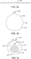
- a method of forming a restraining member in accordance with the present disclosure is generally illustrated by the sequence of Figures 3a through 3c , in which a restraining member have a multi-stage deployment is formed by interconnecting portions of a flexible sheet together to form a releasable seam to define a lumen with a first outer peripheral dimension and interconnecting other portions of the flexible sheet together to form another releasable seam to reduce the size of the lumen to a second outer peripheral dimension.
- Shown in Figure 3a is an edge view of a flexible sheet material 200 that will be subsequently formed into a restraining member.
- the sheet can be formed by flattening a tube of flexible material, such as ePTFE, so that the resulting lumen is double-walled.
- the sheet 200 is folded over onto itself to form a lumen, as shown in Figure 3b . Portions or edges of the folded sheet 200 are then stitched with a coupling member to form a releasable seam 202. The resulting lumen limits expansion of the device to the intermediate state, as discussed above.
- the cross sectional area 210 roughly illustrates the area in which the device will be constrained.
- the seams 202, 206 are generally radially aligned or positioned substantially along the same side of the area 210. In various other embodiments, however, the seams can be offset rotationally about the area 210. The seams, for example, can be disposed on opposite sides of the area 210 relative to each other.
- the device ( Figure 1 , 104) is initially constrained to a small diameter delivery state as shown in Figure 2a .
- the flexible sleeve 106 while in this small diameter state, has a small or first outer peripheral dimension 208 suitable for endoluminal delivery of the device to a treatment site.
- the sleeve 106 will expand to a larger diameter state or second outer peripheral dimension 204, as shown in Figure 2b , due to a generally radially outward force applied by the expansion of the device 104, either by balloon and/or by a stent or wire frame portion of the device.
- the releasable second seam 202 is actuated which "splits open" the sleeve 106 to allow the device to expand toward the fully deployed outer peripheral dimension and engage surrounding tissue at the treatment site.
- a flexible sleeve used for a constraint can comprise materials similar to those used to form a graft.
- the precursor flexible sheet ( Figure 2a , 200) can be formed from a flattened, thin wall tube.
- a thin wall tube (as well as a sheet) can incorporate "rip-stops" in the form of longitudinal high strength fibers attached or embedded into the sheet or tube wall.
- the device in various embodiments, is releasably coupled to the catheter.
- a partially or fully expanded stent or stent graft may be releasably coupled to a catheter by, for example, removable tie-lines, clips and the like.
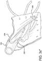
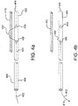
- a catheter shaft 400 having generally opposite distal 404 and proximal ends 406 is positioned adjacent a stent graft wall 412, either internally or externally with respect to the stent graft.
- an elongated member 402 such as a wire, can extend through a distal end 404 of the catheter shaft 400.
- the elongated member 402 can further extend through the catheter lumen and extend outwardly through a distal side wall opening 408.
- the elongated member can form a loop, penetrating the graft wall 412 through at least one aperture 413 in the graft wall 412 and returning into the catheter lumen through a proximal side wall opening 410.
- the elongated member 402 is, by this arrangement, releasably coupled to the graft wall, allowing manipulation and repositioning of the graft as required.
- the elongated member can extend through an apice of a wire frame or at least extend around a portion of the wire frame to releasably couple the catheter shaft to the stent graft wall.
- the catheter 400 can be disengaged from the graft wall 412 to allow removal of the catheter from the treatment site and allow the stent graft to remain in place at the treatment site. More specifically, as shown in Figure 4b , the catheter can be released from the graft wall by retracting the elongated member 402 in a distal direction as depicted by direction arrow 414. The elongated member can exit both catheter side wall holes 408, 410 and be fully withdrawn from the catheter lumen.
- An elongated member 402 can be threaded through a graft wall, through a stent frame or through a graft/stent coupling element such as a hook.
- elongated members can also be attached to a graft through a "cork-screw" configuration. Such a cork-screw can be twisted to engage and penetrate a graft wall (or lock to a stent frame) and be un-twisted to release the elongated member from the graft/stent.
- Elongated members or lock wires in various embodiments, can be formed from metallic, polymeric or natural materials and can comprise conventional medical grade materials such as nylon, polyacrylamide, polycarbonate, polyethylene, polyformaldehyde, polymethylmethacrylate, polypropylene, polytetrafluoroethylene, polytrifluorochlorethylene, polyvinylchloride, polyurethane, elastomeric organosilicon polymers; metals such as stainless steels, cobalt-chromium alloys and nitinol.
- elongated members or lock wires can also be formed from high strength polymer fibers such as ultra high molecular weight polyethylene fibers (e.g., Spectra®, Dyneema Purity®, etc.) or aramid fibers (e.g., Technora®, etc.).
- high strength polymer fibers such as ultra high molecular weight polyethylene fibers (e.g., Spectra®, Dyneema Purity®, etc.) or aramid fibers (e.g., Technora®, etc.).
- the flexible sleeve 106 can be further actuated to allow the sleeve 106 to "split open” and fully release the device 104, as illustrated in Figure 2c .
- the device 104 can then expand toward the fully deployed outer peripheral dimension and engage the vascular wall.
- the catheter can be released from the graft wall of the now-deployed device 104 by retracting the elongated member 402 in a distal direction as depicted by direction arrow 414.
- the elongated member can exit both catheter side wall holes 408, 410 and be fully withdrawn from the catheter lumen.
- Stents can have various configurations as known in the art and can be fabricated, for example, from cut tubes, wound wires (or ribbons) or flat patterned sheets rolled into a tubular form.
- Stents can be formed from metallic, polymeric or natural materials and can comprise conventional medical grade materials such as nylon, polyacrylamide, polycarbonate, polyethylene, polyformaldehyde, polymethylmethacrylate, polypropylene, polytetrafluoroethylene, polytrifluorochlorethylene, polyvinylchloride, polyurethane, elastomeric organosilicon polymers; metals such as stainless steels, cobalt-chromium alloys and nitinol and biologically derived materials such as bovine arteries/veins, pericardium and collagen.
- Stents can also comprise bioresorbable materials such as poly(amino acids), poly(anhydrides), poly(caprolactones), poly(lactic/glycolic acid) polymers, poly(hydroxybutyrates) and poly(orthoesters).
- bioresorbable materials such as poly(amino acids), poly(anhydrides), poly(caprolactones), poly(lactic/glycolic acid) polymers, poly(hydroxybutyrates) and poly(orthoesters).
- a graft member include, for example, expanded polytetrafluoroethylene (ePTFE), polyester, polyurethane, fluoropolymers, such as perfouorelastomers and the like, polytetrafluoroethylene, silicones, urethanes, ultra high molecular weight polyethylene, aramid fibers, and combinations thereof.
- ePTFE expanded polytetrafluoroethylene
- fluoropolymers such as perfouorelastomers and the like
- polytetrafluoroethylene silicones
- urethanes ultra high molecular weight polyethylene
- aramid fibers ultra high molecular weight polyethylene
- the graft member can include a bioactive agent.
- an ePTFE graft includes a carbon component along a blood contacting surface thereof.
- Typical materials used to construct catheters can comprise commonly known materials such as Amorphous Commodity Thermoplastics that include Polymethyl Methacrylate (PMMA or Acrylic), Polystyrene (PS), Acrylonitrile Butadiene Styrene (ABS), Polyvinyl Chloride (PVC), Modified Polyethylene Terephthalate Glycol (PETG), Cellulose Acetate Butyrate (CAB); Semi-Crystalline Commodity Plastics that include Polyethylene (PE), High Density Polyethylene (HDPE), Low Density Polyethylene (LDPE or LLDPE), Polypropylene (PP), Polymethylpentene (PMP); Amorphous Engineering Thermoplastics that include Polycarbonate (PC), Polyphenylene Oxide (PPO), Modified Polyphenylene Oxide (Mod PPO), Polyphenelyne Ether (PPE), Modified Polyphenelyne Ether (Mod PPE),Thermoplastic Polyurethane (TPU); Semi-Crystalline Engineering Therm
Description
- This application is a non-provisional of, and claims priority to,
U.S. Provisional Patent Application No. 61/412,647 - The present disclosure relates to the transcatheter delivery and remote deployment of implantable medical devices and, more particularly, implantable intraluminal devices of either the self-expanding type or the balloon expandable type.
- Endoluminal therapies typically involve the insertion of a delivery catheter that transports an implantable prosthetic device into the vasculature through a small, often percutaneous, access site in a remote vessel. Once access to the vasculature is achieved, the delivery catheter is used to mediate intraluminal delivery and subsequent deployment of the prosthesis via one of several techniques. In this fashion, the prosthesis can be remotely implanted to achieve a therapeutic outcome. In contrast to conventional surgical therapies, endoluminal treatments are distinguished by their "minimally invasive" nature.
- Expandable endoprostheses are generally comprised of a stent component with or without a graft covering over the stent interstices. They are designed to spontaneously dilate (i.e., elastically recover) or to be balloon-expanded from their delivery diameter, through a range of intermediary diameters, up to a maximal, predetermined functional diameter. The endoluminal delivery and deployment of expandable endoprostheses pose several unique problems. First, the endoprosthesis itself must be radially compacted to a suitable introductory size (or delivery diameter) to allow insertion into the vasculature, then it must be constrained in that compacted state and mounted onto a delivery device such as a catheter shaft. Subsequently, the constraint must be removed in order to allow the endoprosthesis to expand to its functional diameter and achieve the desired therapeutic outcome. A variety of ways of constraining and releasing an expandable device are known in the art.
-
US 2006/0015171 A1 discloses a constraining sheath for use around an endoprosthesis. The endoprosthesis is coaxially enclosed within and substantially covered by the constraining sheath, which is an outer, removable tubular sheath, preferably made of ePTFE. The sheath is preferably corrugated circumferentially along at least a portion of the length of the endoprosthesis. The constraining sheath and endoprosthesis are preferably mounted together as an assembly at the distal end of a delivery means such as a catheter shaft, for delivery of the endoprosthesis to a desired location within a body conduit such as an artery. The constraining sheath is removed by the application of tension to a tensile member such as a tether to cause sequential pulling out of the corrugations followed by release and deployment of the endoprosthesis. The use of a corrugated constraining sheath in comparison to a non-corrugated sheath results in a more smoothly applied tensile force to effect the endoprosthesis release as well as requiring less maximum force. Another stent delivery catheter is disclosed inUS5873906 . - It remains desirable to provide improved systems for endoluminal delivery of stents or stent grafts to vascular treatment sites.
- This need is overcome by a catheter assembly according to claim 1 and a method of manufacture of the catheter assembly according to claim 9.
- In the following drawings:
-
Fig. 1 is a side view of a catheter assembly having a compacted and constrained medical device near a distal end of the catheter. -
Figs. 2a through 2c are partial side perspective views of an expandable medical device shown in various stages of deployment. -
Figs. 3a through 3c ,3c' and3c" are side views and perspective views depicting a method of making a flexible constraining sleeve with two releasable seams. -
Figs 4a through 4c are side views and a perspective view of a lock wire for releasably coupling the medical device to the catheter. - Persons skilled in the art will readily appreciate that various aspects of the present disclosure can be realized by any number of methods and apparatuses configured to perform the intended functions. Stated differently, other methods and apparatuses can be incorporated herein to perform the intended functions. It should also be noted that the accompanying drawing figures referred to herein are not all drawn to scale, but can be exaggerated to illustrate various aspects of the present disclosure, and in that regard, the drawing figures should not be construed as limiting. Finally, although the present disclosure can be described in connection with various principles and beliefs, the present disclosure should not be bound by theory.
- Throughout this specification and in the claims, the term "distal" can refer to a location that is, or a portion of an intraluminal device (such as a stent-graft) that when implanted is, further downstream with respect to blood flow than another portion of the device. Similarly, the term "distally" can refer to the direction of blood flow or further downstream in the direction of blood flow.
- The term "proximal" can refer to a location that is, or a portion of an intraluminal device that when implanted is, further upstream with respect to blood flow. Similarly, the term "proximally" can refer to the direction opposite to the direction of blood flow or upstream from the direction of blood flow.
- With further regard to the terms proximal and distal, and because the present disclosure is not limited to peripheral and/or central approaches, this disclosure should not be narrowly construed with respect to these terms. Rather, the devices and methods described herein can be altered and/or adjusted relative to the anatomy of a patient.
- In various embodiments, a catheter assembly is disclosed which utilizes a single flexible sleeve that releasably maintains an expandable device, such as an expandable endoluminal graft, to a dimension suitable for endoluminal delivery of the device to a treatment site, such as a vascular member in a patient's body; and further limits expansion of the device to an outer peripheral dimension that is smaller than an unconstrained or fully deployed outer peripheral dimension thereby facilitating selective axial and/or rotational positioning of the device at the treatment site prior to full deployment and expansion of the device toward engagement with inner walls of the vasculature at the treatment site.
- In various embodiments, for example as shown in
Figure 1 , the catheter assembly, which is generally indicated at 100, includes acatheter 102, anexpandable device 104 and a restraining member orflexible sleeve 106. Thecatheter 102 extends longitudinally and has opposite proximal 110 and distal 108 ends. Thecatheter 102 also includes alumen 112 extending between the proximal 110 and distal 108 ends. - The
expandable device 104 is disposed at or near theproximal end 110 of thecatheter 102. Thedevice 104 is expandable to engage surrounding tissue at the treatment site, such as inner surfaces of a vascular member. Thedevice 104 can include a self-expanding nitinol frame that expands thedevice 104 upon deployment at the treatment site. Thedevice 104 can also be balloon expandable. - In various embodiments, the
flexible sleeve 106 extends around thedevice 104 and has a first outerperipheral dimension 208, at which theflexible sleeve 106 constrains and releasably maintains thedevice 104 in a collapsed state or small diameter delivery profile suitable for endoluminal delivery and advancement through typical vasculature to a treatment site. Fully opening thesleeve 106 allows thedevice 104 to fully expand toward an unconstrained or fully deployed outer peripheral dimension of thedevice 104, wherein thedevice 104 is fully expanded and not constrained by the flexible sleeve and/or vasculature. It should be appreciated that the device can be oversized relative to the intended vasculature to be treated to promote engagement between the device and the inner walls of the vasculature at the treatment site. - The flexible sleeve can have various configurations for constraining the sleeve. In various embodiments, the
sleeve 106 includes generally opposite portions or edges each with a plurality of openings. The openings are arranged to form stitch lines that extend along the opposite portions of thesleeve 106. Thesleeve 106 can extend around thedevice 104 and the opposite portions brought together to form areleasable seam 206, as shown inFigure 2a . Thereleasable seam 206 can be held together by an elongated coupling member extending through or woven through the openings. Examples of coupling members include control tethers, wires, lines, and the like. The control member can extend through acatheter shaft 102 and be accessed through proximal connectors as indicated, for example, at 112, 114 or 116. Tensioning, actuation and displacement of the coupling member from the openings allows thesleeve 106 to open along theseam 206 and thedevice 104 to expand toward a larger diameter. Examples of restraining members and coupling members for releasably maintaining expandable devices in a collapsed state for endoluminal delivery can be found inU.S. 6,352,561 to Leopold et al. - According to the invention the
flexible sleeve 106 is configured to maintain thedevice 104 in an intermediate state, as illustrated inFigure 2b , in which thesleeve 106 is maintained at a second outer peripheral dimension that is larger than the first outer peripheral dimension of thesleeve 106, yet smaller than the fully deployed outer peripheral dimension of thedevice 104. Thus, when thedevice 104 is positioned generally at or near the treatment site, theflexible sleeve 106 can be actuated to allow thesleeve 106 to expand or be pushed outwardly toward the intermediate state by a generally radially outward force applied by expansion of thedevice 104 by, for example, a balloon and/or by a stent or wire frame portion of the device. Maintaining the device in the intermediate state allows the clinician to adjust the axial and/or rotational position of the device with respect to the vasculature prior to full release and expansion of the device toward the fully deployed outer peripheral dimension and engagement with surrounding vasculature tissue. - According to the invention the sleeve is maintained in this intermediate state or second outer
peripheral dimension 204 by a secondreleasable seam 202 held together by a portion of the same coupling member used to secure the first releasable seam or, alternatively, by a separate coupling member separate from the first releasable seam, which, however, is not covered by the invention. Thus, in various embodiments, a single flexible sleeve is formed having a multi-stage deployment. In a dual stage configuration, for example, the sleeve can have a first outer peripheral dimension, indicated at 208 inFigure 2a , releasably maintained by a firstreleasable seam 206 and a second outer peripheral dimension, indicated at 204 inFigure 2b , releasably maintained by a secondreleasable seam 202. In various other embodiments, the sleeve can be formed with more than two states or stages and associated multiple outer peripheral dimensions can be utilized leading toward the final fully deployed outer peripheral dimension by incorporating additional releasable seam arrangements. - A method of forming a restraining member in accordance with the present disclosure is generally illustrated by the sequence of
Figures 3a through 3c , in which a restraining member have a multi-stage deployment is formed by interconnecting portions of a flexible sheet together to form a releasable seam to define a lumen with a first outer peripheral dimension and interconnecting other portions of the flexible sheet together to form another releasable seam to reduce the size of the lumen to a second outer peripheral dimension. Shown inFigure 3a is an edge view of aflexible sheet material 200 that will be subsequently formed into a restraining member. In various embodiments, the sheet can be formed by flattening a tube of flexible material, such as ePTFE, so that the resulting lumen is double-walled. - The
sheet 200 is folded over onto itself to form a lumen, as shown inFigure 3b . Portions or edges of the foldedsheet 200 are then stitched with a coupling member to form areleasable seam 202. The resulting lumen limits expansion of the device to the intermediate state, as discussed above. - Other portions of the flexible sheet are then folded and interconnected to form an additional
releasable seam 206 to further reduce the size of the lumen to an outer peripheral dimension suitable for endoluminal delivery of the device. The crosssectional area 210 roughly illustrates the area in which the device will be constrained. - The
seams Figure 3C , are generally radially aligned or positioned substantially along the same side of thearea 210. In various other embodiments, however, the seams can be offset rotationally about thearea 210. The seams, for example, can be disposed on opposite sides of thearea 210 relative to each other. - To reiterate the delivery sequence, the device (
Figure 1 , 104) is initially constrained to a small diameter delivery state as shown inFigure 2a . Theflexible sleeve 106, while in this small diameter state, has a small or first outerperipheral dimension 208 suitable for endoluminal delivery of the device to a treatment site. When the releasablefirst seam 206 is actuated, thesleeve 106 will expand to a larger diameter state or second outerperipheral dimension 204, as shown inFigure 2b , due to a generally radially outward force applied by the expansion of thedevice 104, either by balloon and/or by a stent or wire frame portion of the device. To complete delivery or full deployment of the device at the treatment site, the releasablesecond seam 202 is actuated which "splits open" thesleeve 106 to allow the device to expand toward the fully deployed outer peripheral dimension and engage surrounding tissue at the treatment site. - In various embodiments, a flexible sleeve used for a constraint can comprise materials similar to those used to form a graft. In various other embodiments, the precursor flexible sheet (
Figure 2a , 200) can be formed from a flattened, thin wall tube. A thin wall tube (as well as a sheet) can incorporate "rip-stops" in the form of longitudinal high strength fibers attached or embedded into the sheet or tube wall. - To allow manipulation and repositioning of the partially expanded device via a catheter, the device, in various embodiments, is releasably coupled to the catheter. In various embodiments, a partially or fully expanded stent or stent graft may be releasably coupled to a catheter by, for example, removable tie-lines, clips and the like.
- In other embodiments, as shown in
Figures 4a and4c , acatheter shaft 400 having generally opposite distal 404 and proximal ends 406 is positioned adjacent astent graft wall 412, either internally or externally with respect to the stent graft. To releasably couple thecatheter shaft 400 to thestent graft wall 412, anelongated member 402, such as a wire, can extend through adistal end 404 of thecatheter shaft 400. Theelongated member 402 can further extend through the catheter lumen and extend outwardly through a distalside wall opening 408. The elongated member can form a loop, penetrating thegraft wall 412 through at least oneaperture 413 in thegraft wall 412 and returning into the catheter lumen through a proximalside wall opening 410. Theelongated member 402 is, by this arrangement, releasably coupled to the graft wall, allowing manipulation and repositioning of the graft as required. Alternatively, the elongated member can extend through an apice of a wire frame or at least extend around a portion of the wire frame to releasably couple the catheter shaft to the stent graft wall. - When the graft is positioned at a desired location along the treatment site, the
catheter 400 can be disengaged from thegraft wall 412 to allow removal of the catheter from the treatment site and allow the stent graft to remain in place at the treatment site. More specifically, as shown inFigure 4b , the catheter can be released from the graft wall by retracting theelongated member 402 in a distal direction as depicted bydirection arrow 414. The elongated member can exit both catheter side wall holes 408, 410 and be fully withdrawn from the catheter lumen. - An
elongated member 402, as shown inFigure 4b , can be threaded through a graft wall, through a stent frame or through a graft/stent coupling element such as a hook. In various embodiments, elongated members can also be attached to a graft through a "cork-screw" configuration. Such a cork-screw can be twisted to engage and penetrate a graft wall (or lock to a stent frame) and be un-twisted to release the elongated member from the graft/stent. - Elongated members or lock wires, in various embodiments, can be formed from metallic, polymeric or natural materials and can comprise conventional medical grade materials such as nylon, polyacrylamide, polycarbonate, polyethylene, polyformaldehyde, polymethylmethacrylate, polypropylene, polytetrafluoroethylene, polytrifluorochlorethylene, polyvinylchloride, polyurethane, elastomeric organosilicon polymers; metals such as stainless steels, cobalt-chromium alloys and nitinol. In other various embodiments, elongated members or lock wires can also be formed from high strength polymer fibers such as ultra high molecular weight polyethylene fibers (e.g., Spectra®, Dyneema Purity®, etc.) or aramid fibers (e.g., Technora®, etc.).
- When the graft is positioned at a desired location along the treatment site, the
flexible sleeve 106 can be further actuated to allow thesleeve 106 to "split open" and fully release thedevice 104, as illustrated inFigure 2c . Thedevice 104 can then expand toward the fully deployed outer peripheral dimension and engage the vascular wall. Referring back toFigure 4b , the catheter can be released from the graft wall of the now-deployeddevice 104 by retracting theelongated member 402 in a distal direction as depicted bydirection arrow 414. The elongated member can exit both catheter side wall holes 408, 410 and be fully withdrawn from the catheter lumen. - Stents can have various configurations as known in the art and can be fabricated, for example, from cut tubes, wound wires (or ribbons) or flat patterned sheets rolled into a tubular form. Stents can be formed from metallic, polymeric or natural materials and can comprise conventional medical grade materials such as nylon, polyacrylamide, polycarbonate, polyethylene, polyformaldehyde, polymethylmethacrylate, polypropylene, polytetrafluoroethylene, polytrifluorochlorethylene, polyvinylchloride, polyurethane, elastomeric organosilicon polymers; metals such as stainless steels, cobalt-chromium alloys and nitinol and biologically derived materials such as bovine arteries/veins, pericardium and collagen. Stents can also comprise bioresorbable materials such as poly(amino acids), poly(anhydrides), poly(caprolactones), poly(lactic/glycolic acid) polymers, poly(hydroxybutyrates) and poly(orthoesters).
- Potential materials for a graft member include, for example, expanded polytetrafluoroethylene (ePTFE), polyester, polyurethane, fluoropolymers, such as perfouorelastomers and the like, polytetrafluoroethylene, silicones, urethanes, ultra high molecular weight polyethylene, aramid fibers, and combinations thereof. One preferred embodiment for a graft material is ePTFE. Other embodiments for a graft member material can include high strength polymer fibers such as ultra high molecular weight polyethylene fibers (e.g., Spectra®, Dyneema Purity®, etc.) or aramid fibers (e.g., Technora®, etc.). The graft member can include a bioactive agent. In one embodiment, an ePTFE graft includes a carbon component along a blood contacting surface thereof.
- Typical materials used to construct catheters can comprise commonly known materials such as Amorphous Commodity Thermoplastics that include Polymethyl Methacrylate (PMMA or Acrylic), Polystyrene (PS), Acrylonitrile Butadiene Styrene (ABS), Polyvinyl Chloride (PVC), Modified Polyethylene Terephthalate Glycol (PETG), Cellulose Acetate Butyrate (CAB); Semi-Crystalline Commodity Plastics that include Polyethylene (PE), High Density Polyethylene (HDPE), Low Density Polyethylene (LDPE or LLDPE), Polypropylene (PP), Polymethylpentene (PMP); Amorphous Engineering Thermoplastics that include Polycarbonate (PC), Polyphenylene Oxide (PPO), Modified Polyphenylene Oxide (Mod PPO), Polyphenelyne Ether (PPE), Modified Polyphenelyne Ether (Mod PPE),Thermoplastic Polyurethane (TPU); Semi-Crystalline Engineering Thermoplastics that include Polyamide (PA or Nylon), Polyoxymethylene (POM or Acetal), Polyethylene Terephthalate (PET, Thermoplastic Polyester), Polybutylene Terephthalate (PBT, Thermoplastic Polyester), Ultra High Molecular Weight Polyethylene (UHMW-PE); High Performance Thermoplastics that include Polyimide (PI, Imidized Plastic), Polyamide Imide (PAI, Imidized Plastic), Polybenzimidazole (PBI, Imidized Plastic); Amorphous High Performance Thermoplastics that include Polysulfone (PSU), Polyetherimide (PEI), Polyether Sulfone (PES), Polyaryl Sulfone (PAS); Semi-Crystalline High Performance Thermoplastics that include Polyphenylene Sulfide (PPS), Polyetheretherketone (PEEK); and Semi-Crystalline High Performance Thermoplastics, Fluoropolymers that include Fluorinated Ethylene Propylene (FEP), Ethylene Chlorotrifluroethylene (ECTFE), Ethylene, Ethylene Tetrafluoroethylene (ETFE), Polychlortrifluoroethylene (PCTFE), Polytetrafluoroethylene (PTFE), Polyvinylidene Fluoride (PVDF), Perfluoroalkoxy (PFA). Other commonly known medical grade materials include elastomeric organosilicon polymers, polyether block amide or thermoplastic copolyether (PEBAX) and metals such as stainless steel and nickel/titanium alloys.
- It will be apparent to those skilled in the art that various modifications and variations can be made in the present invention within the scope of the appended claims and their equivalents.
Claims (13)
- A catheter assembly comprising:a catheter (102) having opposite proximal and distal ends, the catheter having a lumen extending between the proximal and distal ends of the catheter;an expandable device (104) disposed at the distal end of the catheter and expandable toward a fully deployed outer peripheral dimension; anda flexible sleeve (106) extending around the device, characterised in that the flexible sleeve has a releasable first seam (206) that maintains the sleeve at a first dimension suitable for endoluminal delivery (208) of the device to a treatment site, and a releasable second seam (202) that maintains the sleeve at a second dimension (204) larger than the first dimension (208) and smaller than the fully deployed outer peripheral dimension of the device (104), wherein the first and second seams (206, 202) are releasably held together by a common coupling member.
- The catheter assembly as set forth in claim 1, wherein the coupling member comprises a control tether, a wire, or a line.
- The catheter assembly as set forth in claim 1, wherein a substantial portion of an inner surface of the flexible sleeve (106) remains in contact with the device (104) before and after actuation of the second coupling member.
- The catheter assembly as set forth in claim 1, wherein the device (104) remains constrained by the flexible sleeve (106) both before and after actuation of the first coupling member.
- The catheter assembly as set forth in claim 1, wherein the first seam (206) and second seam (202) are generally radially aligned with respect to a longitudinal axis of the catheter, optionally
wherein the second seam (202) is disposed between the longitudinal axis of the catheter (102) and the first seam (206); and optionally
wherein the flexible sleeve (106) is formed from a flattened tube to form a double-walled lumen extending about the device (104), and optionally
wherein the flattened tube is formed of ePTFE. - A catheter assembly as set forth in claim 1, wherein
the releasable first seam (206) maintains the sleeve at a first outer peripheral dimension (208) suitable for endoluminal delivery and deployment of the device to a treatment site, and the releasable second seam (202) limits expansion of the sleeve (106) to a second outer peripheral dimension (204) larger than the first outer peripheral dimension (208) and smaller than the fully deployed outer peripheral dimension of the device (104) after release of the releasable first seam (206). - The catheter assembly as set forth in claim 6 including at least a portion of an elongated member (402) extending through the catheter lumen and being movable relative to the catheter (400).
- The catheter assembly as set forth in claim 7, wherein a portion of the elongated member (402) exits the catheter lumen through a distal side wall opening (408) so as to extend along an outside surface of the catheter, and enters the catheter lumen through a proximal side wall opening (410); optionally
wherein the portion of the elongated member (402) engages the device between the distal and proximal side openings (408, 410) thereby releasably coupling the device and the catheter; and optionally
wherein the device (104) includes a stent frame and the portion of the elongated member (402) engages the stent frame thereby releasably coupling the device (104) and the catheter (400); and optionally
wherein the portion of the elongated member (402) extends between an apice of the stent frame and a graft wall (412) thereby releasably coupling the device (104) and the catheter (400). - A method of forming a catheter assembly, said method comprising:releasably coupling an expandable device (104) and a catheter (102);forming a restraining member (106) by releasably interconnecting opposing portions of a flexible sheet (200) together to form a releasable seam (206) with a coupling member to maintain the restraining member and device at a first outer peripheral dimension (208) suitable for endoluminal delivery of the device to a treatment site, and by releasably interconnecting other opposing portions of the flexible sheet together to form another releasable seam (202) with the coupling member to maintain the restraining member and device at a second outer peripheral dimension (204) larger than the first outer peripheral dimension (208) and smaller than a fully deployed outer peripheral dimension of the device (104).
- The method as set forth in claim 9 including maintaining each of the releasable seams (202, 206) with an elongated member woven along a plurality of openings formed along opposing portions of the flexible sheet.
- The method as set forth in claim 9 including loading the device (104) in a compacted state in the restraining member and retaining the device in the first outer peripheral dimension (208).
- The method as set forth in claim 9 including releasably coupling the device (104) and the catheter (400) by extending an elongated member (402) through the catheter (400) and through a portion of the device (104).
- The method as set forth in claim 12 including weaving the elongated member (402) between portions of a graft wall (412) and a stent frame of the device, optionally loading the device in a compacted state in the restraining member while the device (104) and catheter (400) are releasably coupled by the elongated member (402) and retaining the device (104) in the first outer peripheral dimension (208).
Applications Claiming Priority (3)
| Application Number | Priority Date | Filing Date | Title |
|---|---|---|---|
| US41264710P | 2010-11-11 | 2010-11-11 | |
| US13/293,933 US9468547B2 (en) | 2010-11-11 | 2011-11-10 | Deployment of endoluminal devices |
| PCT/US2011/060397 WO2012065080A2 (en) | 2010-11-11 | 2011-11-11 | Deployment of endoluminal devices |
Publications (2)
| Publication Number | Publication Date |
|---|---|
| EP2637611A2 EP2637611A2 (en) | 2013-09-18 |
| EP2637611B1 true EP2637611B1 (en) | 2019-10-02 |
Family
ID=44999967
Family Applications (1)
| Application Number | Title | Priority Date | Filing Date |
|---|---|---|---|
| EP11785264.0A Active EP2637611B1 (en) | 2010-11-11 | 2011-11-11 | Deployment catheter for endoluminal devices |
Country Status (9)
| Country | Link |
|---|---|
| US (2) | US9468547B2 (en) |
| EP (1) | EP2637611B1 (en) |
| JP (1) | JP6039571B2 (en) |
| CN (1) | CN103209661B (en) |
| AU (1) | AU2011325983B2 (en) |
| BR (1) | BR112013011530A2 (en) |
| CA (1) | CA2815331C (en) |
| RU (1) | RU2013126600A (en) |
| WO (1) | WO2012065080A2 (en) |
Families Citing this family (81)
| Publication number | Priority date | Publication date | Assignee | Title |
|---|---|---|---|---|
| US8858610B2 (en) | 2009-01-19 | 2014-10-14 | W. L. Gore & Associates, Inc. | Forced deployment sequence |
| US8870950B2 (en) | 2009-12-08 | 2014-10-28 | Mitral Tech Ltd. | Rotation-based anchoring of an implant |
| US20110224785A1 (en) | 2010-03-10 | 2011-09-15 | Hacohen Gil | Prosthetic mitral valve with tissue anchors |
| US9763657B2 (en) | 2010-07-21 | 2017-09-19 | Mitraltech Ltd. | Techniques for percutaneous mitral valve replacement and sealing |
| US11653910B2 (en) | 2010-07-21 | 2023-05-23 | Cardiovalve Ltd. | Helical anchor implantation |
| US20120130475A1 (en) * | 2010-11-16 | 2012-05-24 | Shaw Edward E | Sleeves for expandable medical devices |
| US8641752B1 (en) * | 2011-01-20 | 2014-02-04 | W. L. Gore & Associates, Inc. | Integrated sheath and deployment |
| US9744033B2 (en) | 2011-04-01 | 2017-08-29 | W.L. Gore & Associates, Inc. | Elastomeric leaflet for prosthetic heart valves |
| US10117765B2 (en) * | 2011-06-14 | 2018-11-06 | W.L. Gore Associates, Inc | Apposition fiber for use in endoluminal deployment of expandable implants |
| WO2013021374A2 (en) | 2011-08-05 | 2013-02-14 | Mitraltech Ltd. | Techniques for percutaneous mitral valve replacement and sealing |
| WO2013021375A2 (en) | 2011-08-05 | 2013-02-14 | Mitraltech Ltd. | Percutaneous mitral valve replacement and sealing |
| US8852272B2 (en) | 2011-08-05 | 2014-10-07 | Mitraltech Ltd. | Techniques for percutaneous mitral valve replacement and sealing |
| US20140324164A1 (en) * | 2011-08-05 | 2014-10-30 | Mitraltech Ltd. | Techniques for percutaneous mitral valve replacement and sealing |
| US10213329B2 (en) | 2011-08-12 | 2019-02-26 | W. L. Gore & Associates, Inc. | Evertable sheath devices, systems, and methods |
| US9554806B2 (en) | 2011-09-16 | 2017-01-31 | W. L. Gore & Associates, Inc. | Occlusive devices |
| US9877858B2 (en) | 2011-11-14 | 2018-01-30 | W. L. Gore & Associates, Inc. | External steerable fiber for use in endoluminal deployment of expandable devices |
| US9782282B2 (en) | 2011-11-14 | 2017-10-10 | W. L. Gore & Associates, Inc. | External steerable fiber for use in endoluminal deployment of expandable devices |
| US9375308B2 (en) | 2012-03-13 | 2016-06-28 | W. L. Gore & Associates, Inc. | External steerable fiber for use in endoluminal deployment of expandable devices |
| US9283072B2 (en) | 2012-07-25 | 2016-03-15 | W. L. Gore & Associates, Inc. | Everting transcatheter valve and methods |
| US20140106951A1 (en) * | 2012-10-15 | 2014-04-17 | W. L. Gore & Associates, Inc. | Methods and systems for securing a sleeve for endoluminal devices |
| US8628571B1 (en) | 2012-11-13 | 2014-01-14 | Mitraltech Ltd. | Percutaneously-deliverable mechanical valve |
| US9737398B2 (en) | 2012-12-19 | 2017-08-22 | W. L. Gore & Associates, Inc. | Prosthetic valves, frames and leaflets and methods thereof |
| US10039638B2 (en) | 2012-12-19 | 2018-08-07 | W. L. Gore & Associates, Inc. | Geometric prosthetic heart valves |
| US9101469B2 (en) | 2012-12-19 | 2015-08-11 | W. L. Gore & Associates, Inc. | Prosthetic heart valve with leaflet shelving |
| US10966820B2 (en) | 2012-12-19 | 2021-04-06 | W. L. Gore & Associates, Inc. | Geometric control of bending character in prosthetic heart valve leaflets |
| US9144492B2 (en) | 2012-12-19 | 2015-09-29 | W. L. Gore & Associates, Inc. | Truncated leaflet for prosthetic heart valves, preformed valve |
| US9968443B2 (en) | 2012-12-19 | 2018-05-15 | W. L. Gore & Associates, Inc. | Vertical coaptation zone in a planar portion of prosthetic heart valve leaflet |
| US9681952B2 (en) | 2013-01-24 | 2017-06-20 | Mitraltech Ltd. | Anchoring of prosthetic valve supports |
| US9763819B1 (en) * | 2013-03-05 | 2017-09-19 | W. L. Gore & Associates, Inc. | Tapered sleeve |
| DE102013106463A1 (en) * | 2013-06-20 | 2014-12-24 | Jotec Gmbh | stent graft |
| US11911258B2 (en) | 2013-06-26 | 2024-02-27 | W. L. Gore & Associates, Inc. | Space filling devices |
| US9907641B2 (en) | 2014-01-10 | 2018-03-06 | W. L. Gore & Associates, Inc. | Implantable intraluminal device |
| US10966850B2 (en) | 2014-03-06 | 2021-04-06 | W. L. Gore & Associates, Inc. | Implantable medical device constraint and deployment apparatus |
| WO2016016899A1 (en) | 2014-07-30 | 2016-02-04 | Mitraltech Ltd. | Articulatable prosthetic valve |
| US10314697B2 (en) | 2014-08-18 | 2019-06-11 | W. L. Gore & Associates, Inc. | Frame with integral sewing cuff for prosthetic valves |
| US9827094B2 (en) | 2014-09-15 | 2017-11-28 | W. L. Gore & Associates, Inc. | Prosthetic heart valve with retention elements |
| CA3162308A1 (en) | 2015-02-05 | 2016-08-11 | Cardiovalve Ltd. | Prosthetic valve with axially-sliding frames |
| US9974651B2 (en) | 2015-02-05 | 2018-05-22 | Mitral Tech Ltd. | Prosthetic valve with axially-sliding frames |
| EP3294150B1 (en) | 2015-05-14 | 2021-12-15 | W. L. Gore & Associates, Inc. | Devices for occlusion of an atrial appendage |
| US10531866B2 (en) | 2016-02-16 | 2020-01-14 | Cardiovalve Ltd. | Techniques for providing a replacement valve and transseptal communication |
| USD800908S1 (en) | 2016-08-10 | 2017-10-24 | Mitraltech Ltd. | Prosthetic valve element |
| US10856975B2 (en) | 2016-08-10 | 2020-12-08 | Cardiovalve Ltd. | Prosthetic valve with concentric frames |
| ES2810401T3 (en) * | 2016-08-24 | 2021-03-08 | Gore & Ass | Expandable Medical Device Sleeves |
| ES2874197T3 (en) | 2016-09-15 | 2021-11-04 | Gore & Ass | Staged deployment of expandable implant |
| US10537426B2 (en) | 2017-08-03 | 2020-01-21 | Cardiovalve Ltd. | Prosthetic heart valve |
| US10888421B2 (en) | 2017-09-19 | 2021-01-12 | Cardiovalve Ltd. | Prosthetic heart valve with pouch |
| US10575948B2 (en) | 2017-08-03 | 2020-03-03 | Cardiovalve Ltd. | Prosthetic heart valve |
| US11246704B2 (en) | 2017-08-03 | 2022-02-15 | Cardiovalve Ltd. | Prosthetic heart valve |
| US11793633B2 (en) | 2017-08-03 | 2023-10-24 | Cardiovalve Ltd. | Prosthetic heart valve |
| CN111182856B (en) | 2017-09-12 | 2022-04-29 | W.L.戈尔及同仁股份有限公司 | Leaflet frame attachment for prosthetic valves |
| CN115024861A (en) | 2017-09-27 | 2022-09-09 | W.L.戈尔及同仁股份有限公司 | Prosthetic valve with mechanically coupled leaflets |
| CA3178271A1 (en) | 2017-09-27 | 2019-04-04 | W.L. Gore & Associates, Inc. | Prosthetic valve with expandable frame and associated systems and methods |
| ES2960532T3 (en) | 2017-10-11 | 2024-03-05 | Gore & Ass | Implantable medical device restraint and deployment apparatus |
| CA3078699C (en) | 2017-10-13 | 2023-10-10 | W.L. Gore & Associates, Inc. | Telescoping prosthetic valve and delivery system |
| US11173023B2 (en) | 2017-10-16 | 2021-11-16 | W. L. Gore & Associates, Inc. | Medical devices and anchors therefor |
| AU2018362079B2 (en) | 2017-10-31 | 2021-09-16 | Edwards Lifesciences Corporation | Medical valve and leaflet promoting tissue ingrowth |
| JP7227240B2 (en) | 2017-10-31 | 2023-02-21 | ダブリュ.エル.ゴア アンド アソシエイツ,インコーポレイティド | artificial heart valve |
| WO2019089135A1 (en) | 2017-10-31 | 2019-05-09 | W. L. Gore & Associates, Inc. | Transcatheter deployment systems and associated methods |
| US11154397B2 (en) | 2017-10-31 | 2021-10-26 | W. L. Gore & Associates, Inc. | Jacket for surgical heart valve |
| GB201720803D0 (en) | 2017-12-13 | 2018-01-24 | Mitraltech Ltd | Prosthetic Valve and delivery tool therefor |
| GB201800399D0 (en) | 2018-01-10 | 2018-02-21 | Mitraltech Ltd | Temperature-control during crimping of an implant |
| WO2019195860A2 (en) | 2018-04-04 | 2019-10-10 | Vdyne, Llc | Devices and methods for anchoring transcatheter heart valve |
| US11344413B2 (en) | 2018-09-20 | 2022-05-31 | Vdyne, Inc. | Transcatheter deliverable prosthetic heart valves and methods of delivery |
| US10321995B1 (en) | 2018-09-20 | 2019-06-18 | Vdyne, Llc | Orthogonally delivered transcatheter heart valve replacement |
| US11278437B2 (en) | 2018-12-08 | 2022-03-22 | Vdyne, Inc. | Compression capable annular frames for side delivery of transcatheter heart valve replacement |
| US10595994B1 (en) | 2018-09-20 | 2020-03-24 | Vdyne, Llc | Side-delivered transcatheter heart valve replacement |
| US11071627B2 (en) | 2018-10-18 | 2021-07-27 | Vdyne, Inc. | Orthogonally delivered transcatheter heart valve frame for valve in valve prosthesis |
| US11109969B2 (en) | 2018-10-22 | 2021-09-07 | Vdyne, Inc. | Guidewire delivery of transcatheter heart valve |
| USD926322S1 (en) | 2018-11-07 | 2021-07-27 | W. L. Gore & Associates, Inc. | Heart valve cover |
| US11045628B2 (en) | 2018-12-11 | 2021-06-29 | Biosense Webster (Israel) Ltd. | Balloon catheter with high articulation |
| US11253359B2 (en) | 2018-12-20 | 2022-02-22 | Vdyne, Inc. | Proximal tab for side-delivered transcatheter heart valves and methods of delivery |
| US11185409B2 (en) | 2019-01-26 | 2021-11-30 | Vdyne, Inc. | Collapsible inner flow control component for side-delivered transcatheter heart valve prosthesis |
| US11273032B2 (en) | 2019-01-26 | 2022-03-15 | Vdyne, Inc. | Collapsible inner flow control component for side-deliverable transcatheter heart valve prosthesis |
| US11497601B2 (en) | 2019-03-01 | 2022-11-15 | W. L. Gore & Associates, Inc. | Telescoping prosthetic valve with retention element |
| CN113543750A (en) | 2019-03-05 | 2021-10-22 | 维迪内股份有限公司 | Tricuspid valve regurgitation control apparatus for orthogonal transcatheter heart valve prosthesis |
| US11173027B2 (en) | 2019-03-14 | 2021-11-16 | Vdyne, Inc. | Side-deliverable transcatheter prosthetic valves and methods for delivering and anchoring the same |
| US11076956B2 (en) | 2019-03-14 | 2021-08-03 | Vdyne, Inc. | Proximal, distal, and anterior anchoring tabs for side-delivered transcatheter mitral valve prosthesis |
| JP2022530764A (en) | 2019-05-04 | 2022-07-01 | ブイダイン,インコーポレイテッド | Tightening device and method for deploying a laterally delivered artificial heart valve with a native annulus. |
| CN114599316A (en) | 2019-08-20 | 2022-06-07 | 维迪内股份有限公司 | Delivery and retrieval devices and methods for sidedly deliverable transcatheter prosthetic valves |
| WO2021040996A1 (en) | 2019-08-26 | 2021-03-04 | Vdyne, Inc. | Side-deliverable transcatheter prosthetic valves and methods for delivering and anchoring the same |
| US11234813B2 (en) | 2020-01-17 | 2022-02-01 | Vdyne, Inc. | Ventricular stability elements for side-deliverable prosthetic heart valves and methods of delivery |
Family Cites Families (50)
| Publication number | Priority date | Publication date | Assignee | Title |
|---|---|---|---|---|
| US4406656A (en) | 1981-06-01 | 1983-09-27 | Brack Gillium Hattler | Venous catheter having collapsible multi-lumens |
| US4738666A (en) | 1985-06-11 | 1988-04-19 | Genus Catheter Technologies, Inc. | Variable diameter catheter |
| US5106368A (en) | 1990-04-20 | 1992-04-21 | Cook Incorporated | Collapsible lumen catheter for extracorporeal treatment |
| US5531717A (en) | 1993-12-12 | 1996-07-02 | Rtc, Inc. | Non-contaminating probe and methods of making and using same |
| IT225683Y1 (en) | 1991-06-07 | 1997-01-13 | Roberto Feliziani | NON-POLLUTING CATHETER OR PROBE. |
| EP0754016B1 (en) | 1994-04-01 | 2003-07-09 | Prograft Medical, Inc. | Self-expandable stent and stent-graft |
| US5472418A (en) | 1994-07-28 | 1995-12-05 | Palestrant; Aubrey M. | Flattened collapsible vascular catheter |
| US6015429A (en) * | 1994-09-08 | 2000-01-18 | Gore Enterprise Holdings, Inc. | Procedures for introducing stents and stent-grafts |
| US5569219A (en) | 1994-09-13 | 1996-10-29 | Hakki; A-Hamid | Collapsible catheter |
| US5676688A (en) | 1995-02-06 | 1997-10-14 | Rtc, Inc. | Variably inflatable medical device |
| WO1998007450A2 (en) | 1996-08-14 | 1998-02-26 | Rtc, Inc. | Membranes suitable for medical use |
| US5807311A (en) | 1996-11-29 | 1998-09-15 | Palestrant; Aubrey M. | Dialysis catheter having rigid and collapsible lumens and related method |
| US5827243A (en) | 1996-11-29 | 1998-10-27 | Palestrant; Aubrey M. | Collapsible aspiration catheter |
| US6352561B1 (en) * | 1996-12-23 | 2002-03-05 | W. L. Gore & Associates | Implant deployment apparatus |
| US5868708A (en) | 1997-05-07 | 1999-02-09 | Applied Medical Resources Corporation | Balloon catheter apparatus and method |
| AU7577598A (en) | 1997-05-12 | 1998-12-08 | Rtc Inc. | Electrically conductive membrane suitable for medical uses |
| US6224627B1 (en) * | 1998-06-15 | 2001-05-01 | Gore Enterprise Holdings, Inc. | Remotely removable covering and support |
| US7044134B2 (en) | 1999-11-08 | 2006-05-16 | Ev3 Sunnyvale, Inc | Method of implanting a device in the left atrial appendage |
| JP2000149537A (en) | 1999-01-01 | 2000-05-30 | Sony Corp | Display method and function display device |
| US6096013A (en) | 1999-03-04 | 2000-08-01 | Canox International Ltd. | Collapsible urinary catheter |
| US6398802B1 (en) | 1999-06-21 | 2002-06-04 | Scimed Life Systems, Inc. | Low profile delivery system for stent and graft deployment |
| JP3680652B2 (en) | 1999-08-06 | 2005-08-10 | Jfeスチール株式会社 | Manufacturing method of H-section steel |
| JP2001085024A (en) | 1999-09-10 | 2001-03-30 | Toyobo Co Ltd | Carbon electrode material assembly |
| JP2003521971A (en) | 1999-10-12 | 2003-07-22 | ウィル,アラン アール | Method and apparatus for protecting passages in the body |
| AU2001259429A1 (en) | 2000-05-02 | 2001-11-12 | Wilson-Cook Medical Inc. | Introducer device for catheters o.t.l. with eversible sleeve |
| US6926509B2 (en) | 2002-05-31 | 2005-08-09 | Ndh Medical, Inc. | Apparatus for extruding tubing having a variable wall thickness |
| US20040097957A1 (en) | 2002-10-18 | 2004-05-20 | Marc Jaker | Medical device, drug delivery and lab sampling system utilizing an inverting sheath technology |
| US20040106199A1 (en) | 2002-12-02 | 2004-06-03 | Eliseev Alexey V. | Charged cyclodextrin derivatives and their use in plant cell and tissue culture growth media |
| US7771463B2 (en) * | 2003-03-26 | 2010-08-10 | Ton Dai T | Twist-down implant delivery technologies |
| US20050131523A1 (en) | 2003-04-02 | 2005-06-16 | Mehran Bashiri | Detachable and retrievable stent assembly |
| US20040225349A1 (en) | 2003-05-09 | 2004-11-11 | Thistle Robert C. | Eversible locking mechanism for modular stents |
| US7235093B2 (en) | 2003-05-20 | 2007-06-26 | Boston Scientific Scimed, Inc. | Mechanism to improve stent securement |
| US8840663B2 (en) | 2003-12-23 | 2014-09-23 | Sadra Medical, Inc. | Repositionable heart valve method |
| US9254213B2 (en) * | 2004-01-09 | 2016-02-09 | Rubicon Medical, Inc. | Stent delivery device |
| US7425202B2 (en) | 2004-03-05 | 2008-09-16 | Percutaneous Systems, Inc. | Non-seeding biopsy device and method |
| US20050197627A1 (en) | 2004-03-05 | 2005-09-08 | Percutaneous Systems, Inc. | Method and system for deploying protective sleeve in intraluminal catherization and dilation |
| US7462183B2 (en) | 2004-07-07 | 2008-12-09 | Percutaneous Systems, Inc. | Methods for deploying conformed structures in body lumens |
| US8308789B2 (en) | 2004-07-16 | 2012-11-13 | W. L. Gore & Associates, Inc. | Deployment system for intraluminal devices |
| US7758626B2 (en) | 2004-07-20 | 2010-07-20 | Medtronic Vascular, Inc. | Device and method for delivering an endovascular stent-graft having a longitudinally unsupported portion |
| EP1804719A2 (en) | 2004-09-22 | 2007-07-11 | Lee R. Guterman | Cranial aneurysm treatment arrangement |
| US7727163B2 (en) | 2004-09-27 | 2010-06-01 | Percutaneous Systems, Inc. | Methods and apparatus for hollow body structure resection |
| US7255687B2 (en) | 2004-11-19 | 2007-08-14 | Percutaneous Systems, Inc. | Systems and methods for luminal access |
| US20060173525A1 (en) | 2005-02-02 | 2006-08-03 | Percutaneous Systems, Inc. | Methods and systems for deploying luminal prostheses |
| US8414633B2 (en) | 2005-07-21 | 2013-04-09 | Cook Medical Technologies Llc | Stent delivery system with a retention wire |
| US7356725B2 (en) | 2005-09-09 | 2008-04-08 | International Business Machines Corporation | Method and apparatus for adjusting a time of day clock without adjusting the stepping rate of an oscillator |
| US20070106233A1 (en) | 2005-10-20 | 2007-05-10 | Percutaneous Systems, Inc. | Systems and methods for dilating and accessing body lumens |
| GB0620495D0 (en) | 2006-10-16 | 2006-11-22 | Anson Medical Ltd | Apparatus and method for positioning a stent graft |
| US8088154B2 (en) | 2007-03-31 | 2012-01-03 | Cook Medical Technologies Llc | Medical device delivery system with sheath separation |
| CN201131824Y (en) * | 2007-11-30 | 2008-10-15 | 李潮 | Intracavity rack senter |
| US7998189B2 (en) | 2008-10-10 | 2011-08-16 | Cook Medical Technologies Llc | Curvable stent-graft and apparatus and fitting method |
-
2011
- 2011-11-10 US US13/293,933 patent/US9468547B2/en active Active
- 2011-11-11 JP JP2013538938A patent/JP6039571B2/en active Active
- 2011-11-11 EP EP11785264.0A patent/EP2637611B1/en active Active
- 2011-11-11 AU AU2011325983A patent/AU2011325983B2/en active Active
- 2011-11-11 CN CN201180054547.4A patent/CN103209661B/en active Active
- 2011-11-11 RU RU2013126600/14A patent/RU2013126600A/en not_active Application Discontinuation
- 2011-11-11 BR BR112013011530A patent/BR112013011530A2/en not_active Application Discontinuation
- 2011-11-11 WO PCT/US2011/060397 patent/WO2012065080A2/en active Application Filing
- 2011-11-11 CA CA2815331A patent/CA2815331C/en active Active
-
2013
- 2013-09-13 US US14/026,162 patent/US9468549B2/en active Active
Non-Patent Citations (1)
| Title |
|---|
| None * |
Also Published As
| Publication number | Publication date |
|---|---|
| CA2815331C (en) | 2015-10-13 |
| US9468549B2 (en) | 2016-10-18 |
| RU2013126600A (en) | 2014-12-20 |
| JP2014502180A (en) | 2014-01-30 |
| AU2011325983B2 (en) | 2015-09-24 |
| EP2637611A2 (en) | 2013-09-18 |
| US20140018900A1 (en) | 2014-01-16 |
| US20120130473A1 (en) | 2012-05-24 |
| BR112013011530A2 (en) | 2016-08-09 |
| CA2815331A1 (en) | 2012-05-18 |
| CN103209661A (en) | 2013-07-17 |
| WO2012065080A3 (en) | 2012-07-19 |
| JP6039571B2 (en) | 2016-12-07 |
| WO2012065080A2 (en) | 2012-05-18 |
| AU2011325983A1 (en) | 2013-05-09 |
| US9468547B2 (en) | 2016-10-18 |
| CN103209661B (en) | 2015-11-25 |
Similar Documents
| Publication | Publication Date | Title |
|---|---|---|
| EP2637611B1 (en) | Deployment catheter for endoluminal devices | |
| CA2815843C (en) | Apposition fiber for use in endoluminal deployment of expandable devices in tortuous anatomies | |
| US8961582B2 (en) | Integrated sheath and deployment | |
| CA2815841C (en) | Deployment sleeve shortening mechanism | |
| US9060894B2 (en) | Catheter sheath for implant delivery | |
| JP2010535578A (en) | Intraluminal prosthetic conduit system and coupling method | |
| AU2015218452B2 (en) | Apposition fiber for use in endoluminal deployment of expandable devices in tortuous anatomies |
Legal Events
| Date | Code | Title | Description |
|---|---|---|---|
| PUAI | Public reference made under article 153(3) epc to a published international application that has entered the european phase |
Free format text: ORIGINAL CODE: 0009012 |
|
| 17P | Request for examination filed |
Effective date: 20130610 |
|
| AK | Designated contracting states |
Kind code of ref document: A2 Designated state(s): AL AT BE BG CH CY CZ DE DK EE ES FI FR GB GR HR HU IE IS IT LI LT LU LV MC MK MT NL NO PL PT RO RS SE SI SK SM TR |
|
| DAX | Request for extension of the european patent (deleted) | ||
| RAP1 | Party data changed (applicant data changed or rights of an application transferred) |
Owner name: W. L. GORE & ASSOCIATES, INC. |
|
| REG | Reference to a national code |
Ref country code: HK Ref legal event code: DE Ref document number: 1188112 Country of ref document: HK |
|
| 17Q | First examination report despatched |
Effective date: 20160415 |
|
| REG | Reference to a national code |
Ref country code: DE Ref legal event code: R079 Ref document number: 602011062473 Country of ref document: DE Free format text: PREVIOUS MAIN CLASS: A61F0002840000 Ipc: A61F0002962000 |
|
| RIC1 | Information provided on ipc code assigned before grant |
Ipc: A61F 2/962 20130101AFI20180226BHEP |
|
| GRAP | Despatch of communication of intention to grant a patent |
Free format text: ORIGINAL CODE: EPIDOSNIGR1 |
|
| STAA | Information on the status of an ep patent application or granted ep patent |
Free format text: STATUS: GRANT OF PATENT IS INTENDED |
|
| INTG | Intention to grant announced |
Effective date: 20180507 |
|
| GRAJ | Information related to disapproval of communication of intention to grant by the applicant or resumption of examination proceedings by the epo deleted |
Free format text: ORIGINAL CODE: EPIDOSDIGR1 |
|
| STAA | Information on the status of an ep patent application or granted ep patent |
Free format text: STATUS: EXAMINATION IS IN PROGRESS |
|
| INTC | Intention to grant announced (deleted) | ||
| GRAP | Despatch of communication of intention to grant a patent |
Free format text: ORIGINAL CODE: EPIDOSNIGR1 |
|
| STAA | Information on the status of an ep patent application or granted ep patent |
Free format text: STATUS: GRANT OF PATENT IS INTENDED |
|
| INTG | Intention to grant announced |
Effective date: 20190508 |
|
| GRAS | Grant fee paid |
Free format text: ORIGINAL CODE: EPIDOSNIGR3 |
|
| GRAA | (expected) grant |
Free format text: ORIGINAL CODE: 0009210 |
|
| STAA | Information on the status of an ep patent application or granted ep patent |
Free format text: STATUS: THE PATENT HAS BEEN GRANTED |
|
| AK | Designated contracting states |
Kind code of ref document: B1 Designated state(s): AL AT BE BG CH CY CZ DE DK EE ES FI FR GB GR HR HU IE IS IT LI LT LU LV MC MK MT NL NO PL PT RO RS SE SI SK SM TR |
|
| REG | Reference to a national code |
Ref country code: GB Ref legal event code: FG4D |
|
| REG | Reference to a national code |
Ref country code: CH Ref legal event code: EP Ref country code: AT Ref legal event code: REF Ref document number: 1185378 Country of ref document: AT Kind code of ref document: T Effective date: 20191015 |
|
| REG | Reference to a national code |
Ref country code: DE Ref legal event code: R096 Ref document number: 602011062473 Country of ref document: DE |
|
| REG | Reference to a national code |
Ref country code: IE Ref legal event code: FG4D |
|
| REG | Reference to a national code |
Ref country code: NL Ref legal event code: MP Effective date: 20191002 |
|
| REG | Reference to a national code |
Ref country code: LT Ref legal event code: MG4D |
|
| REG | Reference to a national code |
Ref country code: AT Ref legal event code: MK05 Ref document number: 1185378 Country of ref document: AT Kind code of ref document: T Effective date: 20191002 |
|
| PG25 | Lapsed in a contracting state [announced via postgrant information from national office to epo] |
Ref country code: BG Free format text: LAPSE BECAUSE OF FAILURE TO SUBMIT A TRANSLATION OF THE DESCRIPTION OR TO PAY THE FEE WITHIN THE PRESCRIBED TIME-LIMIT Effective date: 20200102 Ref country code: FI Free format text: LAPSE BECAUSE OF FAILURE TO SUBMIT A TRANSLATION OF THE DESCRIPTION OR TO PAY THE FEE WITHIN THE PRESCRIBED TIME-LIMIT Effective date: 20191002 Ref country code: PT Free format text: LAPSE BECAUSE OF FAILURE TO SUBMIT A TRANSLATION OF THE DESCRIPTION OR TO PAY THE FEE WITHIN THE PRESCRIBED TIME-LIMIT Effective date: 20200203 Ref country code: PL Free format text: LAPSE BECAUSE OF FAILURE TO SUBMIT A TRANSLATION OF THE DESCRIPTION OR TO PAY THE FEE WITHIN THE PRESCRIBED TIME-LIMIT Effective date: 20191002 Ref country code: NL Free format text: LAPSE BECAUSE OF FAILURE TO SUBMIT A TRANSLATION OF THE DESCRIPTION OR TO PAY THE FEE WITHIN THE PRESCRIBED TIME-LIMIT Effective date: 20191002 Ref country code: LV Free format text: LAPSE BECAUSE OF FAILURE TO SUBMIT A TRANSLATION OF THE DESCRIPTION OR TO PAY THE FEE WITHIN THE PRESCRIBED TIME-LIMIT Effective date: 20191002 Ref country code: SE Free format text: LAPSE BECAUSE OF FAILURE TO SUBMIT A TRANSLATION OF THE DESCRIPTION OR TO PAY THE FEE WITHIN THE PRESCRIBED TIME-LIMIT Effective date: 20191002 Ref country code: NO Free format text: LAPSE BECAUSE OF FAILURE TO SUBMIT A TRANSLATION OF THE DESCRIPTION OR TO PAY THE FEE WITHIN THE PRESCRIBED TIME-LIMIT Effective date: 20200102 Ref country code: AT Free format text: LAPSE BECAUSE OF FAILURE TO SUBMIT A TRANSLATION OF THE DESCRIPTION OR TO PAY THE FEE WITHIN THE PRESCRIBED TIME-LIMIT Effective date: 20191002 Ref country code: GR Free format text: LAPSE BECAUSE OF FAILURE TO SUBMIT A TRANSLATION OF THE DESCRIPTION OR TO PAY THE FEE WITHIN THE PRESCRIBED TIME-LIMIT Effective date: 20200103 Ref country code: LT Free format text: LAPSE BECAUSE OF FAILURE TO SUBMIT A TRANSLATION OF THE DESCRIPTION OR TO PAY THE FEE WITHIN THE PRESCRIBED TIME-LIMIT Effective date: 20191002 Ref country code: ES Free format text: LAPSE BECAUSE OF FAILURE TO SUBMIT A TRANSLATION OF THE DESCRIPTION OR TO PAY THE FEE WITHIN THE PRESCRIBED TIME-LIMIT Effective date: 20191002 |
|
| PG25 | Lapsed in a contracting state [announced via postgrant information from national office to epo] |
Ref country code: CZ Free format text: LAPSE BECAUSE OF FAILURE TO SUBMIT A TRANSLATION OF THE DESCRIPTION OR TO PAY THE FEE WITHIN THE PRESCRIBED TIME-LIMIT Effective date: 20191002 Ref country code: HR Free format text: LAPSE BECAUSE OF FAILURE TO SUBMIT A TRANSLATION OF THE DESCRIPTION OR TO PAY THE FEE WITHIN THE PRESCRIBED TIME-LIMIT Effective date: 20191002 Ref country code: IS Free format text: LAPSE BECAUSE OF FAILURE TO SUBMIT A TRANSLATION OF THE DESCRIPTION OR TO PAY THE FEE WITHIN THE PRESCRIBED TIME-LIMIT Effective date: 20200224 Ref country code: RS Free format text: LAPSE BECAUSE OF FAILURE TO SUBMIT A TRANSLATION OF THE DESCRIPTION OR TO PAY THE FEE WITHIN THE PRESCRIBED TIME-LIMIT Effective date: 20191002 |
|
| PG25 | Lapsed in a contracting state [announced via postgrant information from national office to epo] |
Ref country code: AL Free format text: LAPSE BECAUSE OF FAILURE TO SUBMIT A TRANSLATION OF THE DESCRIPTION OR TO PAY THE FEE WITHIN THE PRESCRIBED TIME-LIMIT Effective date: 20191002 |
|
| REG | Reference to a national code |
Ref country code: CH Ref legal event code: PL |
|
| REG | Reference to a national code |
Ref country code: DE Ref legal event code: R097 Ref document number: 602011062473 Country of ref document: DE |
|
| PG2D | Information on lapse in contracting state deleted |
Ref country code: IS |
|
| PG25 | Lapsed in a contracting state [announced via postgrant information from national office to epo] |
Ref country code: EE Free format text: LAPSE BECAUSE OF FAILURE TO SUBMIT A TRANSLATION OF THE DESCRIPTION OR TO PAY THE FEE WITHIN THE PRESCRIBED TIME-LIMIT Effective date: 20191002 Ref country code: DK Free format text: LAPSE BECAUSE OF FAILURE TO SUBMIT A TRANSLATION OF THE DESCRIPTION OR TO PAY THE FEE WITHIN THE PRESCRIBED TIME-LIMIT Effective date: 20191002 Ref country code: RO Free format text: LAPSE BECAUSE OF FAILURE TO SUBMIT A TRANSLATION OF THE DESCRIPTION OR TO PAY THE FEE WITHIN THE PRESCRIBED TIME-LIMIT Effective date: 20191002 Ref country code: LI Free format text: LAPSE BECAUSE OF NON-PAYMENT OF DUE FEES Effective date: 20191130 Ref country code: CH Free format text: LAPSE BECAUSE OF NON-PAYMENT OF DUE FEES Effective date: 20191130 Ref country code: LU Free format text: LAPSE BECAUSE OF NON-PAYMENT OF DUE FEES Effective date: 20191111 Ref country code: MC Free format text: LAPSE BECAUSE OF FAILURE TO SUBMIT A TRANSLATION OF THE DESCRIPTION OR TO PAY THE FEE WITHIN THE PRESCRIBED TIME-LIMIT Effective date: 20191002 Ref country code: IS Free format text: LAPSE BECAUSE OF FAILURE TO SUBMIT A TRANSLATION OF THE DESCRIPTION OR TO PAY THE FEE WITHIN THE PRESCRIBED TIME-LIMIT Effective date: 20200202 |
|
| PLBE | No opposition filed within time limit |
Free format text: ORIGINAL CODE: 0009261 |
|
| STAA | Information on the status of an ep patent application or granted ep patent |
Free format text: STATUS: NO OPPOSITION FILED WITHIN TIME LIMIT |
|
| REG | Reference to a national code |
Ref country code: BE Ref legal event code: MM Effective date: 20191130 |
|
| PG25 | Lapsed in a contracting state [announced via postgrant information from national office to epo] |
Ref country code: SM Free format text: LAPSE BECAUSE OF FAILURE TO SUBMIT A TRANSLATION OF THE DESCRIPTION OR TO PAY THE FEE WITHIN THE PRESCRIBED TIME-LIMIT Effective date: 20191002 Ref country code: SK Free format text: LAPSE BECAUSE OF FAILURE TO SUBMIT A TRANSLATION OF THE DESCRIPTION OR TO PAY THE FEE WITHIN THE PRESCRIBED TIME-LIMIT Effective date: 20191002 |
|
| 26N | No opposition filed |
Effective date: 20200703 |
|
| PG25 | Lapsed in a contracting state [announced via postgrant information from national office to epo] |
Ref country code: BE Free format text: LAPSE BECAUSE OF NON-PAYMENT OF DUE FEES Effective date: 20191130 Ref country code: SI Free format text: LAPSE BECAUSE OF FAILURE TO SUBMIT A TRANSLATION OF THE DESCRIPTION OR TO PAY THE FEE WITHIN THE PRESCRIBED TIME-LIMIT Effective date: 20191002 |
|
| PG25 | Lapsed in a contracting state [announced via postgrant information from national office to epo] |
Ref country code: CY Free format text: LAPSE BECAUSE OF FAILURE TO SUBMIT A TRANSLATION OF THE DESCRIPTION OR TO PAY THE FEE WITHIN THE PRESCRIBED TIME-LIMIT Effective date: 20191002 |
|
| PG25 | Lapsed in a contracting state [announced via postgrant information from national office to epo] |
Ref country code: MT Free format text: LAPSE BECAUSE OF FAILURE TO SUBMIT A TRANSLATION OF THE DESCRIPTION OR TO PAY THE FEE WITHIN THE PRESCRIBED TIME-LIMIT Effective date: 20191002 Ref country code: HU Free format text: LAPSE BECAUSE OF FAILURE TO SUBMIT A TRANSLATION OF THE DESCRIPTION OR TO PAY THE FEE WITHIN THE PRESCRIBED TIME-LIMIT; INVALID AB INITIO Effective date: 20111111 |
|
| PG25 | Lapsed in a contracting state [announced via postgrant information from national office to epo] |
Ref country code: TR Free format text: LAPSE BECAUSE OF FAILURE TO SUBMIT A TRANSLATION OF THE DESCRIPTION OR TO PAY THE FEE WITHIN THE PRESCRIBED TIME-LIMIT Effective date: 20191002 |
|
| PG25 | Lapsed in a contracting state [announced via postgrant information from national office to epo] |
Ref country code: MK Free format text: LAPSE BECAUSE OF FAILURE TO SUBMIT A TRANSLATION OF THE DESCRIPTION OR TO PAY THE FEE WITHIN THE PRESCRIBED TIME-LIMIT Effective date: 20191002 |
|
| P01 | Opt-out of the competence of the unified patent court (upc) registered |
Effective date: 20230516 |
|
| PGFP | Annual fee paid to national office [announced via postgrant information from national office to epo] |
Ref country code: GB Payment date: 20231019 Year of fee payment: 13 |
|
| PGFP | Annual fee paid to national office [announced via postgrant information from national office to epo] |
Ref country code: IT Payment date: 20231019 Year of fee payment: 13 Ref country code: IE Payment date: 20231023 Year of fee payment: 13 Ref country code: FR Payment date: 20231019 Year of fee payment: 13 Ref country code: DE Payment date: 20231019 Year of fee payment: 13 |