EP2637495B1 - Selbstverriegelndes fressgitter - Google Patents
Selbstverriegelndes fressgitter Download PDFInfo
- Publication number
- EP2637495B1 EP2637495B1 EP10776707.1A EP10776707A EP2637495B1 EP 2637495 B1 EP2637495 B1 EP 2637495B1 EP 10776707 A EP10776707 A EP 10776707A EP 2637495 B1 EP2637495 B1 EP 2637495B1
- Authority
- EP
- European Patent Office
- Prior art keywords
- latch
- locking
- self
- feed fence
- coupling element
- Prior art date
- Legal status (The legal status is an assumption and is not a legal conclusion. Google has not performed a legal analysis and makes no representation as to the accuracy of the status listed.)
- Not-in-force
Links
- 230000008878 coupling Effects 0.000 claims description 50
- 238000010168 coupling process Methods 0.000 claims description 50
- 238000005859 coupling reaction Methods 0.000 claims description 50
- 230000007246 mechanism Effects 0.000 claims description 34
- 241000283690 Bos taurus Species 0.000 description 10
- 241001465754 Metazoa Species 0.000 description 4
- 239000000463 material Substances 0.000 description 3
- 238000012544 monitoring process Methods 0.000 description 3
- 230000008901 benefit Effects 0.000 description 2
- 230000005484 gravity Effects 0.000 description 2
- 230000006378 damage Effects 0.000 description 1
- 230000009027 insemination Effects 0.000 description 1
- 244000144972 livestock Species 0.000 description 1
- 238000004519 manufacturing process Methods 0.000 description 1
- 230000004048 modification Effects 0.000 description 1
- 238000012986 modification Methods 0.000 description 1
- 230000000452 restraining effect Effects 0.000 description 1
Images




Classifications
-
- A—HUMAN NECESSITIES
- A01—AGRICULTURE; FORESTRY; ANIMAL HUSBANDRY; HUNTING; TRAPPING; FISHING
- A01K—ANIMAL HUSBANDRY; AVICULTURE; APICULTURE; PISCICULTURE; FISHING; REARING OR BREEDING ANIMALS, NOT OTHERWISE PROVIDED FOR; NEW BREEDS OF ANIMALS
- A01K1/00—Housing animals; Equipment therefor
- A01K1/06—Devices for fastening animals, e.g. halters, toggles, neck-bars or chain fastenings
- A01K1/0606—Devices for fastening animals, e.g. halters, toggles, neck-bars or chain fastenings by means of grids with or without movable locking bars
Definitions
- the invention relates to improvements for self-locking feed fences and self-locking safety feed fences.
- One type of feed fence includes a frame with at least one opening for receiving the head of an animal, e.g. a cow, and a locking device for alternately restraining and releasing the animal.
- the document EP 0 522 665 A1 describes a self-catching feeding fence
- the document US 5,564,368 A illustrates a control system for a livestock pen panel.
- the object of the invention is to provide an improved feed fence having fewer components easy to use.
- the self-locking feed fence is provided with a coupling element to individually couple and uncouple said latch actuator with said unlatch slide, said coupling element being integrated in said latch actuator.
- One advantage of the invention is that no loose components are required and the number of components is reduced.
- a self-locking feed fence comprising at least one pivoting bar, two vertical bars, a top rail, a lower bar and a latch mechanism, said top rail and said lower bar arranged in parallel and connected by said vertical bars forming an opening in which said at least one pivoting bar is arranged and can be moved from an open position forming an upper opening to a locking position forming a closed upper opening and whereby said at least pivoting bar can be moved back to said open position, said at least one pivoting bar being lockable and releasable by the latch mechanism in the locking position, said latch mechanism comprising at least one latch, one unlatch slide and a latch actuator slidably arranged on said top rail, is characterized in that a coupling element is provided to individually couple and uncouple said latch actuator with said unlatch slide, said coupling element being integrated in said latch actuator.
- Said coupling element can be supported by a guide bush fixed to said latch actuator and can be pushed into a coupled position to couple said latch actuator with said unlatch slide, and can be pulled into an uncoupled position to uncouple said latch actuator and said unlatch slide. In this way it is easy to couple and uncouple individually the corresponding unlatch slides and the latch actuator. No additional tools are required.
- said coupling element can be fixed in said uncoupled position by means of profiles engaging with guide sections.
- These components can be made e.g. of plastic material easy to manufacture.
- said coupling element has a twistlock which can be engaged with a coupling seat of the unlatch slide in the coupled position.
- the coupling seat can be manufactured in an easy way and makes coupling an uncoupling easy.
- the coupling element can have an indicator to show its coupled and/or uncoupled state.
- a visible position of said coupling element indicates show the coupled and/or uncoupled state. So the coupling and uncoupling can be seen easily.
- said coupling element comprises or is coupled with an electric switch or position detecting element to provide a signal according to its position. So the position can be easily monitored e.g. in a remote monitoring station.
- the self-locking feed fence can be a self-locking safety feed fence
- said at least one pivoting bar can be moved from an open position forming an upper opening to a locking position, from said locking position forming a closed opening to a safety position forming a lower opening and whereby said at least pivoting bar can be moved back to said open position
- said latch mechanism further comprises an additional latch.
- Said additional latch can be coupled with said latch. Only the additional latch is required and can be activated by said latch without any additional parts.
- the at least one latch can be released individually by means of a release element.
- the latch actuator can be coupled with a lever to obtain a simple and safe handling.
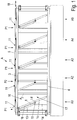
- a self-locking feed fence A according to the invention is shown in figure 1 and comprises at least one pivoting bar 1, two vertical bars 2, a top rail 3, a lower bar 4 and a latch mechanism L.
- the top rail 3 and the lower bar 4 are arranged in parallel and connected by the vertical bars 2. In this way they form an opening.
- Figure 1 shows five openings A1...5. It is to be understood that the feed fence may include any number of openings A1...5.
- a vertical lower side member 14 is arranged in the left third of the opening.
- the upper end of the vertical lower side member 14 is connected to an upper side member 13 which extends in an angle to the upper left corner of the opening.
- the pivoting bar 1 having a swivelling axis 1 d is pivotally attached in a mounting 15.
- the pivoting bars 1 of openings A1 and A3...5 are in an open position P1 and respectively rest with lock ends 1a on the upper side members 13, thereby forming triangular upper openings 16 with their upper sections 1b for e.g. cows to go with heads through the feed fence A.
- the pivoting bars 1 have lower sections 1 c closing lower openings 17 of the openings A1 and A3...5.
- the pivoting bar 1 When a cow having its head in the upper opening 16 moves its head down to eat, the pivoting bar 1 is moved in its locking position P2 which is a vertical position in this embodiment. This is shown for the opening A2 in figure 1 . In this vertical or locking position P2 the pivoting bar 1 is locked by a latch mechanism L which can be released by a release element 11.
- the latch mechanism L will be described in more detail below.
- a latch actuator 5, preferably in a shape of a u-profile, is mounted on the top rail 3 and slidably attached to it. That attachment can be done in different ways and will not be further described.
- the latch actuator 5 can be moved in its axial direction in actuating directions 18. The latch actuator 5 locks all latch mechanisms L in a locking position and unlocks them in an unlocking position.
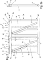
- Figure 2 shows two openings A1 and A2.
- the opening A1 belongs to the feed fence A of figure 1 and the opening A2 belongs to a second feed fence A'.
- Figure 2a shows a view in direction IIa of figure 2 .
- a lever 6 is pivotally attached in a pivot 6a to a side of the top rail 3.
- the lever 6 is also connected to a side of the latch actuator 5 via an actuator pin 6b.
- This can be seen in figure 2a as well.
- a further possibility of connecting feed fences A, A' is shown.
- the respective latch actuators 5, 5' can be connected by a simple connecting link 19 to be movable by only one lever 6. Rotating the lever 6 around the pivot 6a shifts the latch actuator 5 in actuating directions 18.
- Figure 2 shows also coupling elements 9 on top of the latch actuator. The coupling elements 9 can be accessed manually from above and will be explained in more detail below.
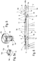
- Figure 3 is a view of the latch mechanism L of the feed fence A shown in figure 1 in an unlocking position and figure 4 is a view of the latch mechanism L of figure 3 in a locking position.
- the latch mechanism L comprises a latch 7, an unlatch slide 8, the release element 11 and a coupling element 9.
- the unlatch slide 8 cooperates with the latch 7.
- the coupling element 9 couples the unlatch slide 8 to the latch actuator 5.
- the latch actuator 5 In the unlocking position shown in figure 3 the latch actuator 5 is shifted by the lever 6 to the left in actuating direction 18. In this way the latch actuator 5 has moved the unlatch slides 8 via the coupling elements 9 to lift the latches 7.
- the pivoting bars 1 can swivel freely.
- the respective release element 11 can pressed down to unlock the respective latch 7.
- the release element 11 contacts a release section 7b of the latch 7.
- the release section 7b is arranged opposite to the locking section 7a of the latch 7.
- the latch 7 has a tilting section 7c supported by the top rail 3. The tilting section 7c enables the latch 7 to swivel around it.
- Figure 5 shows an embodiment of the coupling element 9, and figure 5a is a view of a guide bush 10 for the coupling element 9 of figure 5 .
- the coupling element 9 is a type of a twistlock element. It has a twistlock 9a which can be pushed, pulled and turned by a knob.
- the guide bush 10 is mounted into the latch actuator 5 and fixed to it.
- the twistlock 9a is pushed through a through hole 10a of the guide bush 10.
- An inner profile 10b of the guide bush 10 is provided and engages with an inner vertical guide section 9b and an inner horizontal guide section 9c of the twistlock 9a. This engagement makes it possible that the coupling element 9 can be pulled up und pushed down when the inner profile 10b of the guide bush 10 engages with the inner vertical guide section 9b of the twistlock 9a.
- the coupling element 9 When the coupling element 9 is pulled up completely, the inner profile 10b of the guide bush 10 engages with the inner horizontal guide section 9c of the twistlock 9a and the coupling element 9 can be rotated, e.g. 90 degrees, and stays in that pulled up position. Rotating in opposite direction will enable the coupling element 9 to be pushed down.
- FIG 6 another view of the latch mechanisms 7 of figure 3 is shown in the unlocking position.
- the latch actuator 5 has been shifted by the lever 6 into the unlocking direction 18b to unlock the latches.
- the coupling element 9 of the left latch 7 is pushed down and couples the unlatch slide 8 to the latch actuator 5, as the twistlock 9a of the coupling element 9 is received in a coupling seat 8a of the unlatch slide 8. So the left latch 7 is lifted and unlocked by the shifted unlatch slide 8.
- the coupling element 9 of the right latch 7 is pulled up and rotated to stay in the pulled up position.
- the twistlock 9a is pulled out of the coupling seat 8a of the unlatch slide 8.
- the unlatch slide 8 has not been moved by the latch actuator 5 and the right latch 7 stays in the locking position. In this case all cows have been using the feed fence A have been released except that one of the uncoupled latch 7.
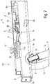
- Figure 7 shows the latch mechanism L of figure 3 in a larger scale in the locking position.
- Figures 8 and 9 show the latch mechanisms L of figure 7 in the unlocking and locking positions.
- the unlatch slide 8 is connected to the coupling seat 8a by a connecting section 8d.
- the part of the unlatch slide 8 cooperating with the latch 7 has two sloping guideways 8b which cooperate with guide parts 7d of the latch 7.
- the guide parts 7d are arranged on both sides of the latch 7 above the locking section 7a. Moving the unlatch slide 8 in direction to the latch 7, the guide parts 7d and the latch 7 will be lifted up and the latch swivels counter clockwise around its tilting section 7c.
- the release element 11 is a type of a push button, has a pressure section 11a on its lower end and is attached to the latch actuator 5. Pressing the release element 11 will cause the latch 7 to swivel counter clockwise from the shown locking position in the unlocking position. This is shown in figure 8 .
- the lock end 1 a of the pivoting bar 1 is guided in a slot between guide sections 3b, 3c of the top rail 3.
- the guide sections 3b, 3c extend in longitudinal direction of the top rail 3.
- the stop block 3a is fixed on the guide sections 3b, 3c.
- the lock end 1a can be made of plastic material. Therefore it can provide a dampening function when the pivoting bar 1 hits its rest positions with said lock end 1 a.
- FIG 9 shows the lock end 1a of the pivoting bar 1 in its locking or locking position P2.
- the latch mechanism L can also be used for a so called self-locking safety feed fence A.
- Figure 11 is a view of a safety feed fence A of the invention. The difference between a safety and a normal self-locking feed fence A is the possibility for a cow (or a similar animal) to leave the fence through the lower opening 17 on the bottom of the feed fence A.
- the pivoting bar 1 contacts with its right stop 1e at the vertical bar 2.
- the lower side member 14 and the upper side member 13 form a triangle.
- the latch mechanism L of the safety feed fence A has an additional latch 12 to enable catching or locking the pivoting bar 1 as there is no stop block 3a.
- Figures 12 and 13 show the latch mechanism L of figure 11 in the unlocking and locking positions.
- Figure 14 is a view of the latch mechanism L of figure 11 in larger detail.
- the additional latch 12 is arranged on the opposite side of latch 7 next to the unlatch slide 8. This can be seen best in figure 14 .
- the additional latch 12 is arranged above the connecting section 8d and between the guideways 8b of the unlatch slide 8.
- the additional latch 12 comprises a locking section 12a similar to the locking section 7a of the latch 7.
- the locking section 12a is arranged opposite to the locking section 7a so that both locking sections 7a and 12a can receive the lock end 1a of the pivoting bar 1 between them as can be seen in figure 13 .
- the additional latch 12 has a lift section 12b which extends in its longitudinal direction towards the latch 7 above an extended lift end 7e of the latch 7.
- the lift end 7e of the latch 7 contacts the bottom side of the lift section 12b of the additional latch 12 between the guideways 8b of the unlatch slide 8.
- the additional latch 12 also has a tilting section 12c which enables the additional latch 12 to swivel around it similar to the latch 7.
- the latch actuator 5 When the latch actuator 5 is moved by the lever 6, the latch 7 is lifted or lowered by the unlatch slide 8 via the guideways 8b and guide parts 7d, the lift end 7e of the latch 7 lifts or lowers the lift section 12b of the additional latch 12 correspondingly. So the unlocking position (shown in figures 12 and 14 ) and locking position (see figure 13 ) will be set as described before.
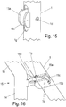
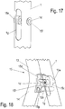
- Figures 15 ... 18 are views of different mountings 15 of the pivoting bar 1.
- Figure 15 shows the section of the pivoting bar 1 with the swivelling axis 1d.
- the pivoting bar 1 preferably made of a tube, has a slot hole 1g in longitudinal direction of the pivoting bar 1 on the side facing to the upper and lower side members 13, 14.
- the slot hole 1g is arranged having the swivelling axis 1d in between.
- cover plates 15a, 15b are mounted and protrude from the slot hole 1 g.
- the cover plates 15a, 15b extend within the pivoting bar 1 around the swivelling axis 1 d and reinforce the pivoting bar 1 around the hole of the swivelling axis 1d.
- Each one of the protruding sections of the cover plates 15a, 15b has a rounded shape to cover a mounting arm 15d of the mounting 15 (see figure 16 ) and to avoid injuries.
- Figure 16 is a view of the mounted pivoting bar 1 of figure 15 .
- the mounting arm 15d extends through the slot hole 1 g between the cover plates 15a, 15b and supports the swivelling axis 1 d with a disk shaped mounting element 15c.
- the mounting 15 of figures 17 and 18 shows mounting bushings 15e, 15f which are arranged within the walls of the pivoting bar 1 around the holes of the swivelling axis 1d.
- the pivoting bar 1 is provided with the slot hole 1g.
- the assembled status of this mounting 15 is shown in figure 18 .
- the mounting arm 15d extends through the slot hole 1 g and supports the mounting element 15c.
- a bolt or pin extends through the holes of the swivelling axis 1 d, the mounting bushings 15e, 15f and the mounting element 15c.
- figure 18 shows a pressure spring element 15h received in a receptacle 15g.
- the receptacle 15 is arranged below the mounting element 15c and can be made integral with it.
- the pressure spring element 15h can be made of rubber material and has a cylindrical shape.
- One end of the pressure spring element 15h is fixed in the receptacle and the other end thereof is inserted through the slot hole 1g into the pivoting bar 1 to press against the inner wall of the pivoting bar. So the pivoting bar 1 is always turned into position P1 when it is released from position P2. In case of a safety feed fence A the pivoting bar 1 will be turned by the pressure spring element 15h as well from position P3 into position P1.
- latch actuator 5 can be provided for only the latch 7 and latch 7 and the additional latch 12, using the same unlatch slide 8.
- the latch actuator 5 is preferably made from a u-profile. Other profiles are possible.
- the latch actuator 5 serves also as a cover of the latches 7.
- figure 19 shows a side view of a lever drive mechanism of the latch device L
- figure 19a shows a top view of figure 19 .
- the lever 6 is pivoted with its lower end in a pivot 6a on a lever support 6d fixed to the top rail 3.
- An eccentric element 6c in the shape of a cylinder is attached to the lower section of the lever 6 and engages between two drive walls 5a which are fixed to the latch actuator 5. Rotating the lever 6 around its pivot 6a, e.g. in a clockwise direction, will cause the eccentric element 6c to an eccentric rotation around pivot 6a. In this manner the eccentric element 6c presses against the right drive wall 5a ( figure 19a ) and therefore the latch actuator 5 will be moved to the right in a corresponding actuating direction 18. Rotating the lever 6 in a counter clockwise direction will move the latch actuator 5 vice versa to the left in the same manner as described above.
- the unlocking position of the latch devices 7 can be seen and well recognized, because the release elements 11 do not protrude from the top surface of the latch actuator 5, 5'. This can be seen clearly in figures 2 , 3 , 6 .
- the locking position of the latch devices 7 can also be seen well recognized by the vertical position of the release elements 11.
- the release elements 11 of the latch devices 7 being in a locking position are in their top position, i.e. the release elements 11 are protruding from the top surface of the latch actuator 5, 5'.
- the coupling elements 9 as well as the release elements 11 can comprise an electric contact or electric position detecting element which is activated according to their position. In this manner a signal can be created and used for monitoring purposes, maybe for remote monitoring the feed fence A. This can be realized by wire or wireless.
- the unlatch slide 8 is firmly attached to the latch actuator without any adjustable coupling element 9.
- the release element 11 is provided to unlock the latch 7 individually.
Landscapes
- Life Sciences & Earth Sciences (AREA)
- Zoology (AREA)
- Environmental Sciences (AREA)
- Animal Husbandry (AREA)
- Biodiversity & Conservation Biology (AREA)
- Lock And Its Accessories (AREA)
- Invalid Beds And Related Equipment (AREA)
- Housing For Livestock And Birds (AREA)
Claims (12)
- Selbstverriegelndes Fressgitter (A), umfassend wenigstens eine Schwenkstange (1), zwei vertikale Stangen (2), eine obere Schiene (3), eine untere Stange (4) und einen Klinkenmechanismus (L), wobei die obere Schiene (3) und die untere Stange (4), die parallel angeordnet sind und durch die vertikalen Stangen (2) verbunden sind, eine Öffnung (A1 ... 5) bilden, in der die wenigstens eine Schwenkstange (1) angeordnet ist und von einer offenen Position (P1), die eine obere Öffnung (16) bildet, in eine Verriegelungsposition (P2), die eine geschlossene obere Öffnung (16) bildet, bewegt werden kann, und wobei die wenigstens eine Schwenkstange (1) zu der offenen Position (P1) zurückbewegt werden kann, wobei die wenigstens eine Schwenkstange (1) durch den Klinkenmechanismus (L) in der Verriegelungsposition (P2) verriegelt und freigegeben werden kann, wobei der Klinkenmechanismus (L) wenigstens eine Klinke (7), einen Entriegelungsschieber (8) und eine Klinkenbetätigungsvorrichtung (5) umfasst, die an der oberen Schiene (3) schiebbar angeordnet ist,
dadurch gekennzeichnet, dass ein Kopplungselement (9) vorgesehen ist, um die Klinkenbetätigungsvorrichtung (5) einzeln mit dem Entriegelungsschieber (8) zu koppeln und davon zu entkoppeln, wobei das Kopplungselement (9) in die Klinkenbetätigungsvorrichtung (5) integriert ist. - Selbstverriegelndes Fressgitter (A) nach Anspruch 1, dadurch gekennzeichnet, dass das Kopplungselement (9) durch eine Führungsbuchse (10) gehalten wird, die an der Klinkenbetätigungsvorrichtung (5) befestigt ist, und in eine gekoppelte Position gedrückt werden kann, um die Klinkenbetätigungsvorrichtung (5) mit dem Entriegelungsschieber (8) zu koppeln, und in eine entkoppelte Position gezogen werden kann, um die Klinkenbetätigungsvorrichtung (5) und den Entriegelungsschieber (8) voneinander zu entkoppeln.
- Selbstverriegelndes Fressgitter (A) nach Anspruch 2, dadurch gekennzeichnet, dass das Kopplungselement (9) mithilfe von Profilen (10b), die in Führungsabschnitte (9b, 9c) eingreifen, in der entkoppelten Position fixiert werden kann.
- Selbstverriegelndes Fressgitter (A) nach Anspruch 2 oder 3, dadurch gekennzeichnet, dass das Kopplungselement (9) einen Riegelzapfen (9a) aufweist, der in der gekoppelten Position mit einem Kopplungssitz (8a) des Entriegelungsschiebers (8) in Eingriff gebracht werden kann.
- Selbstverriegelndes Fressgitter (A) nach einem der Ansprüche 1 bis 4, dadurch gekennzeichnet, dass das Kopplungselement (9) eine Anzeige aufweist, um seinen gekoppelten und/oder entkoppelten Zustand anzuzeigen.
- Selbstverriegelndes Fressgitter (A) nach Anspruch 5, dadurch gekennzeichnet, dass eine sichtbare Position des Kopplungselements (9) den gekoppelten und/oder entkoppelten Zustand anzeigt.
- Selbstverriegelndes Fressgitter (A) nach Anspruch 5 oder 6, dadurch gekennzeichnet, dass das Kopplungselement (9) einen elektrischen Schalter oder ein Positionsdetektionselement umfasst oder damit gekoppelt ist, um ein Signal entsprechend seiner Position bereitzustellen.
- Selbstverriegelndes Fressgitter (A) nach einem der Ansprüche 1 bis 7, wobei das selbstverriegelnde Fressgitter (A) ein selbstverriegelndes Sicherheitsfressgitter (A) ist, wobei die wenigstens eine Schwenkstange (1) wie folgt bewegt werden kann: von einer offenen Position (P1), die eine obere Öffnung (16) bildet, in eine Verriegelungsposition (P2), von der Verriegelungsposition (P2), die eine geschlossene obere Öffnung (16) bildet, in eine Sicherheitsposition (P3), die eine offene untere Öffnung (17) bildet, und wobei die wenigstens eine Schwenkstange (1) in die offene Position (P1) zurückbewegt werden kann, wobei der Klinkenmechanismus (L) ferner eine zusätzliche Klinke (12) umfasst.
- Selbstverriegelndes Fressgitter (A) nach Anspruch 8, dadurch gekennzeichnet, dass die zusätzliche Klinke (12) mit der Klinke (7) gekoppelt ist.
- Selbstverriegelndes Fressgitter (A) nach einem der Ansprüche 1 bis 9, dadurch gekennzeichnet, dass die wenigstens eine Klinke (7) mithilfe von wenigstens einem Freigabeelement (11) einzeln freigegeben werden kann.
- Selbstverriegelndes Fressgitter (A) nach Anspruch 10, dadurch gekennzeichnet, dass das wenigstens eine Freigabeelement (11) eine Art Druckknopf ist, der an seinem unteren Ende einen Druckabschnitt (IIa) aufweist, der mit der wenigstens einen Klinke (7) in Eingriff ist.
- Selbstverriegelndes Fressgitter (A) nach einem der Ansprüche 1 bis 11, dadurch gekennzeichnet, dass die Klinkenbetätigungsvorrichtung (5) mit einem Hebel (6) gekoppelt ist.
Priority Applications (2)
| Application Number | Priority Date | Filing Date | Title |
|---|---|---|---|
| DK13197737.3T DK2737793T3 (en) | 2010-11-12 | 2010-11-12 | SELF-LOCKING DANGERS |
| EP13197737.3A EP2737793B1 (de) | 2010-11-12 | 2010-11-12 | Selbstverriegelnder Futterzaun |
Applications Claiming Priority (1)
| Application Number | Priority Date | Filing Date | Title |
|---|---|---|---|
| PCT/EP2010/067391 WO2012062377A1 (en) | 2010-11-12 | 2010-11-12 | Self-locking feed fence |
Related Child Applications (2)
| Application Number | Title | Priority Date | Filing Date |
|---|---|---|---|
| EP13197737.3A Division-Into EP2737793B1 (de) | 2010-11-12 | 2010-11-12 | Selbstverriegelnder Futterzaun |
| EP13197737.3A Division EP2737793B1 (de) | 2010-11-12 | 2010-11-12 | Selbstverriegelnder Futterzaun |
Publications (2)
| Publication Number | Publication Date |
|---|---|
| EP2637495A1 EP2637495A1 (de) | 2013-09-18 |
| EP2637495B1 true EP2637495B1 (de) | 2017-01-18 |
Family
ID=44246297
Family Applications (2)
| Application Number | Title | Priority Date | Filing Date |
|---|---|---|---|
| EP10776707.1A Not-in-force EP2637495B1 (de) | 2010-11-12 | 2010-11-12 | Selbstverriegelndes fressgitter |
| EP13197737.3A Not-in-force EP2737793B1 (de) | 2010-11-12 | 2010-11-12 | Selbstverriegelnder Futterzaun |
Family Applications After (1)
| Application Number | Title | Priority Date | Filing Date |
|---|---|---|---|
| EP13197737.3A Not-in-force EP2737793B1 (de) | 2010-11-12 | 2010-11-12 | Selbstverriegelnder Futterzaun |
Country Status (4)
| Country | Link |
|---|---|
| EP (2) | EP2637495B1 (de) |
| DK (2) | DK2637495T3 (de) |
| RU (1) | RU2561218C2 (de) |
| WO (1) | WO2012062377A1 (de) |
Families Citing this family (5)
| Publication number | Priority date | Publication date | Assignee | Title |
|---|---|---|---|---|
| CN109287506A (zh) * | 2018-10-22 | 2019-02-01 | 山东环蓝农牧科技有限公司 | 全自动刮草机 |
| CN111418515B (zh) * | 2020-04-10 | 2024-05-31 | 华南农业大学 | 一种可远程监控的仔猪精准喂奶装置 |
| JP7867175B2 (ja) * | 2021-04-15 | 2026-05-29 | 日本発條株式会社 | ロック機構 |
| FR3134497B1 (fr) * | 2022-04-14 | 2024-05-24 | Agritubel | Balancier pour barriere de type cornadis |
| NL2033606B1 (nl) | 2022-11-24 | 2024-05-30 | Lely Patent Nv | Veediermanagementsysteem |
Family Cites Families (7)
| Publication number | Priority date | Publication date | Assignee | Title |
|---|---|---|---|---|
| SU1412676A1 (ru) * | 1987-01-05 | 1988-07-30 | Головное Специализированное Конструкторское Бюро По Комплексу Машин Для Ферм Крупного Рогатого Скота | Прив зь дл животных |
| NL8901158A (nl) * | 1989-05-08 | 1990-12-03 | Johannes Martinus Willibrordus | Verplaatsbaar voerhek. |
| BE1005105A4 (nl) * | 1991-07-12 | 1993-04-20 | Weelink Johannes M W | Zelfvangend voerhek. |
| NL9400142A (nl) * | 1994-01-28 | 1995-09-01 | Boer Stalinrichtingen | Voerhek. |
| US5564368A (en) | 1994-10-03 | 1996-10-15 | Gardner Barn Equipment Company, Inc. | Control system for a livestock pen panel |
| NL1004436C2 (nl) * | 1996-11-05 | 1998-05-08 | Hubertus Renier Maria Timmerma | Voerhek. |
| FR2775557B1 (fr) | 1998-03-06 | 2000-06-09 | Jourdain Ets | Perfectionnements aux cornadis automatiques |
-
2010
- 2010-11-12 EP EP10776707.1A patent/EP2637495B1/de not_active Not-in-force
- 2010-11-12 RU RU2013126166/13A patent/RU2561218C2/ru active
- 2010-11-12 EP EP13197737.3A patent/EP2737793B1/de not_active Not-in-force
- 2010-11-12 WO PCT/EP2010/067391 patent/WO2012062377A1/en not_active Ceased
- 2010-11-12 DK DK10776707.1T patent/DK2637495T3/en active
- 2010-11-12 DK DK13197737.3T patent/DK2737793T3/en active
Non-Patent Citations (1)
| Title |
|---|
| None * |
Also Published As
| Publication number | Publication date |
|---|---|
| EP2637495A1 (de) | 2013-09-18 |
| DK2737793T3 (en) | 2017-05-01 |
| DK2637495T3 (en) | 2017-05-01 |
| RU2013126166A (ru) | 2014-12-20 |
| WO2012062377A1 (en) | 2012-05-18 |
| EP2737793B1 (de) | 2017-01-18 |
| EP2737793A1 (de) | 2014-06-04 |
| RU2561218C2 (ru) | 2015-08-27 |
Similar Documents
| Publication | Publication Date | Title |
|---|---|---|
| EP2737793B1 (de) | Selbstverriegelnder Futterzaun | |
| EP2020474B1 (de) | Schloss | |
| KR20180006456A (ko) | 로크 배열체를 포함하는 로드 캐리어 | |
| EP3787928A1 (de) | Kindersitz mit fangkörper zur anbringung auf einem kraftfahrzeugsitz | |
| EP3073040B1 (de) | Feststeller zum arretieren eines kipp- und/oder schwenkbaren fensterflügels | |
| US4377131A (en) | Stanchion construction | |
| DE102009039322B3 (de) | Vorrichtung zum Verriegeln oder Entriegeln eines Schiebeflügels | |
| GB2309258A (en) | Door latching structure | |
| DE19951289C2 (de) | Sperrvorrichtung und damit versehene Torantriebsvorrichtung für ein mittels eines Motorantriebsaggregats antreibbares Tor | |
| US20060112890A1 (en) | Device for and a method of automatically supplying feed and/or drink to an animal | |
| US20170020106A1 (en) | Vehicle Mounted Animal Enclosure with Unique Door Control Mechanisms | |
| CA3170992C (en) | Free access sow gestation stall gate assembly | |
| DE202007011220U1 (de) | Absperrvorrichtung für eine Tierbox | |
| CA2032002C (en) | Animal gate latch mechanism | |
| EP2818042B1 (de) | Selbstfanggitter | |
| RU2672497C2 (ru) | Самозапирающееся ограждение кормового стола | |
| EP0664950B1 (de) | Fütterungsgitter | |
| CN223854132U (zh) | 一种多功能门栏 | |
| EP2413686A1 (de) | Aufbewahrungsbehälter für haustiere | |
| CA2701400C (en) | Remotely operable gated chute for livestock | |
| CN102934614B (zh) | 一种家畜个体隔离用的可自锁自由进出门 | |
| ES2913630T3 (es) | Barandilla para una cama, jaula guía para una barandilla y una cama con tal barandilla | |
| WO2023028021A1 (en) | Free access sow gestation stall gate assembly | |
| KR102966385B1 (ko) | 우사용 목걸이틀 조립체 | |
| EP1806706A1 (de) | Diebstahlgeschützter behälter für vergnügen und spiel von glücksspielautomaten |
Legal Events
| Date | Code | Title | Description |
|---|---|---|---|
| PUAI | Public reference made under article 153(3) epc to a published international application that has entered the european phase |
Free format text: ORIGINAL CODE: 0009012 |
|
| 17P | Request for examination filed |
Effective date: 20130513 |
|
| AK | Designated contracting states |
Kind code of ref document: A1 Designated state(s): AL AT BE BG CH CY CZ DE DK EE ES FI FR GB GR HR HU IE IS IT LI LT LU LV MC MK MT NL NO PL PT RO RS SE SI SK SM TR |
|
| DAX | Request for extension of the european patent (deleted) | ||
| GRAP | Despatch of communication of intention to grant a patent |
Free format text: ORIGINAL CODE: EPIDOSNIGR1 |
|
| INTG | Intention to grant announced |
Effective date: 20160905 |
|
| GRAS | Grant fee paid |
Free format text: ORIGINAL CODE: EPIDOSNIGR3 |
|
| STAA | Information on the status of an ep patent application or granted ep patent |
Free format text: STATUS: GRANT OF PATENT IS INTENDED |
|
| GRAA | (expected) grant |
Free format text: ORIGINAL CODE: 0009210 |
|
| STAA | Information on the status of an ep patent application or granted ep patent |
Free format text: STATUS: THE PATENT HAS BEEN GRANTED |
|
| AK | Designated contracting states |
Kind code of ref document: B1 Designated state(s): AL AT BE BG CH CY CZ DE DK EE ES FI FR GB GR HR HU IE IS IT LI LT LU LV MC MK MT NL NO PL PT RO RS SE SI SK SM TR |
|
| REG | Reference to a national code |
Ref country code: GB Ref legal event code: FG4D |
|
| REG | Reference to a national code |
Ref country code: CH Ref legal event code: EP |
|
| REG | Reference to a national code |
Ref country code: AT Ref legal event code: REF Ref document number: 862345 Country of ref document: AT Kind code of ref document: T Effective date: 20170215 |
|
| REG | Reference to a national code |
Ref country code: IE Ref legal event code: FG4D |
|
| REG | Reference to a national code |
Ref country code: DE Ref legal event code: R096 Ref document number: 602010039691 Country of ref document: DE |
|
| REG | Reference to a national code |
Ref country code: NL Ref legal event code: FP |
|
| REG | Reference to a national code |
Ref country code: DK Ref legal event code: T3 Effective date: 20170426 |
|
| REG | Reference to a national code |
Ref country code: SE Ref legal event code: TRGR |
|
| REG | Reference to a national code |
Ref country code: LT Ref legal event code: MG4D |
|
| REG | Reference to a national code |
Ref country code: AT Ref legal event code: MK05 Ref document number: 862345 Country of ref document: AT Kind code of ref document: T Effective date: 20170118 |
|
| PG25 | Lapsed in a contracting state [announced via postgrant information from national office to epo] |
Ref country code: IS Free format text: LAPSE BECAUSE OF FAILURE TO SUBMIT A TRANSLATION OF THE DESCRIPTION OR TO PAY THE FEE WITHIN THE PRESCRIBED TIME-LIMIT Effective date: 20170518 Ref country code: HR Free format text: LAPSE BECAUSE OF FAILURE TO SUBMIT A TRANSLATION OF THE DESCRIPTION OR TO PAY THE FEE WITHIN THE PRESCRIBED TIME-LIMIT Effective date: 20170118 Ref country code: LT Free format text: LAPSE BECAUSE OF FAILURE TO SUBMIT A TRANSLATION OF THE DESCRIPTION OR TO PAY THE FEE WITHIN THE PRESCRIBED TIME-LIMIT Effective date: 20170118 Ref country code: GR Free format text: LAPSE BECAUSE OF FAILURE TO SUBMIT A TRANSLATION OF THE DESCRIPTION OR TO PAY THE FEE WITHIN THE PRESCRIBED TIME-LIMIT Effective date: 20170419 Ref country code: NO Free format text: LAPSE BECAUSE OF FAILURE TO SUBMIT A TRANSLATION OF THE DESCRIPTION OR TO PAY THE FEE WITHIN THE PRESCRIBED TIME-LIMIT Effective date: 20170418 Ref country code: FI Free format text: LAPSE BECAUSE OF FAILURE TO SUBMIT A TRANSLATION OF THE DESCRIPTION OR TO PAY THE FEE WITHIN THE PRESCRIBED TIME-LIMIT Effective date: 20170118 |
|
| PG25 | Lapsed in a contracting state [announced via postgrant information from national office to epo] |
Ref country code: LV Free format text: LAPSE BECAUSE OF FAILURE TO SUBMIT A TRANSLATION OF THE DESCRIPTION OR TO PAY THE FEE WITHIN THE PRESCRIBED TIME-LIMIT Effective date: 20170118 Ref country code: PL Free format text: LAPSE BECAUSE OF FAILURE TO SUBMIT A TRANSLATION OF THE DESCRIPTION OR TO PAY THE FEE WITHIN THE PRESCRIBED TIME-LIMIT Effective date: 20170118 Ref country code: AT Free format text: LAPSE BECAUSE OF FAILURE TO SUBMIT A TRANSLATION OF THE DESCRIPTION OR TO PAY THE FEE WITHIN THE PRESCRIBED TIME-LIMIT Effective date: 20170118 Ref country code: BG Free format text: LAPSE BECAUSE OF FAILURE TO SUBMIT A TRANSLATION OF THE DESCRIPTION OR TO PAY THE FEE WITHIN THE PRESCRIBED TIME-LIMIT Effective date: 20170418 Ref country code: PT Free format text: LAPSE BECAUSE OF FAILURE TO SUBMIT A TRANSLATION OF THE DESCRIPTION OR TO PAY THE FEE WITHIN THE PRESCRIBED TIME-LIMIT Effective date: 20170518 Ref country code: RS Free format text: LAPSE BECAUSE OF FAILURE TO SUBMIT A TRANSLATION OF THE DESCRIPTION OR TO PAY THE FEE WITHIN THE PRESCRIBED TIME-LIMIT Effective date: 20170118 Ref country code: ES Free format text: LAPSE BECAUSE OF FAILURE TO SUBMIT A TRANSLATION OF THE DESCRIPTION OR TO PAY THE FEE WITHIN THE PRESCRIBED TIME-LIMIT Effective date: 20170118 |
|
| REG | Reference to a national code |
Ref country code: DE Ref legal event code: R097 Ref document number: 602010039691 Country of ref document: DE |
|
| PG25 | Lapsed in a contracting state [announced via postgrant information from national office to epo] |
Ref country code: CZ Free format text: LAPSE BECAUSE OF FAILURE TO SUBMIT A TRANSLATION OF THE DESCRIPTION OR TO PAY THE FEE WITHIN THE PRESCRIBED TIME-LIMIT Effective date: 20170118 Ref country code: EE Free format text: LAPSE BECAUSE OF FAILURE TO SUBMIT A TRANSLATION OF THE DESCRIPTION OR TO PAY THE FEE WITHIN THE PRESCRIBED TIME-LIMIT Effective date: 20170118 Ref country code: RO Free format text: LAPSE BECAUSE OF FAILURE TO SUBMIT A TRANSLATION OF THE DESCRIPTION OR TO PAY THE FEE WITHIN THE PRESCRIBED TIME-LIMIT Effective date: 20170118 Ref country code: SK Free format text: LAPSE BECAUSE OF FAILURE TO SUBMIT A TRANSLATION OF THE DESCRIPTION OR TO PAY THE FEE WITHIN THE PRESCRIBED TIME-LIMIT Effective date: 20170118 Ref country code: IT Free format text: LAPSE BECAUSE OF FAILURE TO SUBMIT A TRANSLATION OF THE DESCRIPTION OR TO PAY THE FEE WITHIN THE PRESCRIBED TIME-LIMIT Effective date: 20170118 |
|
| PLBE | No opposition filed within time limit |
Free format text: ORIGINAL CODE: 0009261 |
|
| REG | Reference to a national code |
Ref country code: FR Ref legal event code: PLFP Year of fee payment: 8 |
|
| STAA | Information on the status of an ep patent application or granted ep patent |
Free format text: STATUS: NO OPPOSITION FILED WITHIN TIME LIMIT |
|
| PG25 | Lapsed in a contracting state [announced via postgrant information from national office to epo] |
Ref country code: SM Free format text: LAPSE BECAUSE OF FAILURE TO SUBMIT A TRANSLATION OF THE DESCRIPTION OR TO PAY THE FEE WITHIN THE PRESCRIBED TIME-LIMIT Effective date: 20170118 |
|
| 26N | No opposition filed |
Effective date: 20171019 |
|
| PG25 | Lapsed in a contracting state [announced via postgrant information from national office to epo] |
Ref country code: SI Free format text: LAPSE BECAUSE OF FAILURE TO SUBMIT A TRANSLATION OF THE DESCRIPTION OR TO PAY THE FEE WITHIN THE PRESCRIBED TIME-LIMIT Effective date: 20170118 |
|
| PG25 | Lapsed in a contracting state [announced via postgrant information from national office to epo] |
Ref country code: MC Free format text: LAPSE BECAUSE OF FAILURE TO SUBMIT A TRANSLATION OF THE DESCRIPTION OR TO PAY THE FEE WITHIN THE PRESCRIBED TIME-LIMIT Effective date: 20170118 |
|
| GBPC | Gb: european patent ceased through non-payment of renewal fee |
Effective date: 20171112 |
|
| PG25 | Lapsed in a contracting state [announced via postgrant information from national office to epo] |
Ref country code: CH Free format text: LAPSE BECAUSE OF NON-PAYMENT OF DUE FEES Effective date: 20171130 Ref country code: LI Free format text: LAPSE BECAUSE OF NON-PAYMENT OF DUE FEES Effective date: 20171130 |
|
| PG25 | Lapsed in a contracting state [announced via postgrant information from national office to epo] |
Ref country code: LU Free format text: LAPSE BECAUSE OF NON-PAYMENT OF DUE FEES Effective date: 20171112 |
|
| REG | Reference to a national code |
Ref country code: BE Ref legal event code: MM Effective date: 20171130 |
|
| REG | Reference to a national code |
Ref country code: IE Ref legal event code: MM4A |
|
| PG25 | Lapsed in a contracting state [announced via postgrant information from national office to epo] |
Ref country code: MT Free format text: LAPSE BECAUSE OF NON-PAYMENT OF DUE FEES Effective date: 20171112 |
|
| PG25 | Lapsed in a contracting state [announced via postgrant information from national office to epo] |
Ref country code: IE Free format text: LAPSE BECAUSE OF NON-PAYMENT OF DUE FEES Effective date: 20171112 |
|
| PG25 | Lapsed in a contracting state [announced via postgrant information from national office to epo] |
Ref country code: BE Free format text: LAPSE BECAUSE OF NON-PAYMENT OF DUE FEES Effective date: 20171130 Ref country code: GB Free format text: LAPSE BECAUSE OF NON-PAYMENT OF DUE FEES Effective date: 20171112 |
|
| PG25 | Lapsed in a contracting state [announced via postgrant information from national office to epo] |
Ref country code: HU Free format text: LAPSE BECAUSE OF FAILURE TO SUBMIT A TRANSLATION OF THE DESCRIPTION OR TO PAY THE FEE WITHIN THE PRESCRIBED TIME-LIMIT; INVALID AB INITIO Effective date: 20101112 |
|
| PG25 | Lapsed in a contracting state [announced via postgrant information from national office to epo] |
Ref country code: CY Free format text: LAPSE BECAUSE OF NON-PAYMENT OF DUE FEES Effective date: 20170118 |
|
| PG25 | Lapsed in a contracting state [announced via postgrant information from national office to epo] |
Ref country code: MK Free format text: LAPSE BECAUSE OF FAILURE TO SUBMIT A TRANSLATION OF THE DESCRIPTION OR TO PAY THE FEE WITHIN THE PRESCRIBED TIME-LIMIT Effective date: 20170118 |
|
| PG25 | Lapsed in a contracting state [announced via postgrant information from national office to epo] |
Ref country code: TR Free format text: LAPSE BECAUSE OF FAILURE TO SUBMIT A TRANSLATION OF THE DESCRIPTION OR TO PAY THE FEE WITHIN THE PRESCRIBED TIME-LIMIT Effective date: 20170118 |
|
| PG25 | Lapsed in a contracting state [announced via postgrant information from national office to epo] |
Ref country code: AL Free format text: LAPSE BECAUSE OF FAILURE TO SUBMIT A TRANSLATION OF THE DESCRIPTION OR TO PAY THE FEE WITHIN THE PRESCRIBED TIME-LIMIT Effective date: 20170118 |
|
| REG | Reference to a national code |
Ref country code: DE Ref legal event code: R082 Ref document number: 602010039691 Country of ref document: DE Representative=s name: PATENT- UND RECHTSANWAELTE LOESENBECK, SPECHT,, DE Ref country code: DE Ref legal event code: R081 Ref document number: 602010039691 Country of ref document: DE Owner name: ROYAL DE BOER STALINRICHTINGEN B.V., NL Free format text: FORMER OWNERS: GEA FARM TECHNOLOGIES GMBH, 59199 BOENEN, DE; ROYAL DE BOER STALINRICHTINGEN B.V., LEEUWARDEN, NL |
|
| PGFP | Annual fee paid to national office [announced via postgrant information from national office to epo] |
Ref country code: NL Payment date: 20201126 Year of fee payment: 11 |
|
| PGFP | Annual fee paid to national office [announced via postgrant information from national office to epo] |
Ref country code: FR Payment date: 20201127 Year of fee payment: 11 Ref country code: DK Payment date: 20201127 Year of fee payment: 11 Ref country code: SE Payment date: 20201127 Year of fee payment: 11 Ref country code: DE Payment date: 20201201 Year of fee payment: 11 |
|
| REG | Reference to a national code |
Ref country code: NL Ref legal event code: PD Owner name: ROYAL DE BOER STALINRICHTINGEN B.V.; NL Free format text: DETAILS ASSIGNMENT: CHANGE OF OWNER(S), ASSIGNMENT; FORMER OWNER NAME: ROYAL DE BOER STALINRICHTINGEN B.V. Effective date: 20210422 |
|
| REG | Reference to a national code |
Ref country code: DE Ref legal event code: R119 Ref document number: 602010039691 Country of ref document: DE |
|
| REG | Reference to a national code |
Ref country code: DK Ref legal event code: EBP Effective date: 20211130 |
|
| REG | Reference to a national code |
Ref country code: NL Ref legal event code: MM Effective date: 20211201 |
|
| PG25 | Lapsed in a contracting state [announced via postgrant information from national office to epo] |
Ref country code: SE Free format text: LAPSE BECAUSE OF NON-PAYMENT OF DUE FEES Effective date: 20211113 |
|
| PG25 | Lapsed in a contracting state [announced via postgrant information from national office to epo] |
Ref country code: NL Free format text: LAPSE BECAUSE OF NON-PAYMENT OF DUE FEES Effective date: 20211201 |
|
| PG25 | Lapsed in a contracting state [announced via postgrant information from national office to epo] |
Ref country code: DK Free format text: LAPSE BECAUSE OF NON-PAYMENT OF DUE FEES Effective date: 20211130 Ref country code: DE Free format text: LAPSE BECAUSE OF NON-PAYMENT OF DUE FEES Effective date: 20220601 |
|
| PG25 | Lapsed in a contracting state [announced via postgrant information from national office to epo] |
Ref country code: FR Free format text: LAPSE BECAUSE OF NON-PAYMENT OF DUE FEES Effective date: 20211130 |