EP2636957A1 - A cooking oven including a swinging oven door and a closure system for said oven door - Google Patents
A cooking oven including a swinging oven door and a closure system for said oven door Download PDFInfo
- Publication number
- EP2636957A1 EP2636957A1 EP12158284.5A EP12158284A EP2636957A1 EP 2636957 A1 EP2636957 A1 EP 2636957A1 EP 12158284 A EP12158284 A EP 12158284A EP 2636957 A1 EP2636957 A1 EP 2636957A1
- Authority
- EP
- European Patent Office
- Prior art keywords
- oven
- hook
- door
- cooking oven
- cooking
- Prior art date
- Legal status (The legal status is an assumption and is not a legal conclusion. Google has not performed a legal analysis and makes no representation as to the accuracy of the status listed.)
- Granted
Links
- 238000010411 cooking Methods 0.000 title claims abstract description 57
- 229920003023 plastic Polymers 0.000 claims description 7
- 239000004033 plastic Substances 0.000 claims description 7
- 239000000463 material Substances 0.000 claims description 2
- 239000002184 metal Substances 0.000 claims description 2
- 230000003670 easy-to-clean Effects 0.000 description 2
- 238000012986 modification Methods 0.000 description 2
- 230000004048 modification Effects 0.000 description 2
- 230000003287 optical effect Effects 0.000 description 1
- 238000007789 sealing Methods 0.000 description 1
Images




Classifications
-
- F—MECHANICAL ENGINEERING; LIGHTING; HEATING; WEAPONS; BLASTING
- F24—HEATING; RANGES; VENTILATING
- F24C—DOMESTIC STOVES OR RANGES ; DETAILS OF DOMESTIC STOVES OR RANGES, OF GENERAL APPLICATION
- F24C15/00—Details
- F24C15/02—Doors specially adapted for stoves or ranges
- F24C15/022—Latches
Definitions
- the present invention relates to a cooking oven including a swing oven door and a closure system for said swing oven door according to the preamble of claim 1.
- a closure system for a swing door of a household appliance is an important device. If the household appliance is an oven, then the closure system must be heat-resistant in order to guarantee the closing and sealing of the oven door.
- the most closure systems comprise a hook element and a hook seat element, wherein an opening in the hook seat element receives a hook projecting from the hook element.
- the hook element is assembled at the door, and the hook seat element is placed at a door frame, front frame or chassis of the household appliance. The hook element sticks out from the oven door, which may disturb the user and impairs the security.
- WO 2007/080146 A2 discloses a closure system comprising the hook seat at the oven frame and the hook at the oven door.
- the mechanism of the hook is complex.
- US 7,735,480 discloses a closure system for two oven doors.
- the closure system comprises a moveable hook at the oven frame and the hook seat at the oven door.
- the object of the present invention is achieved by the cooking oven including a swing door and a closure system for said swing door according to claim 1.
- the hook element is attached or attachable at an oven frame of an oven chassis, and the hook seat element is attached or attachable at a door frame of an oven door of the cooking oven.
- the oven door has a very compact structure.
- the hook element is arranged at a vertical part of the oven frame.
- the hook element is arranged at a position of the vertical part of the oven frame such that the hook seat element is arranged about at half height of the vertical part of the door frame.
- the hook element may be covered by a side wall of the cooking oven, so that the hook element is invisible for a position lateral of the cooking oven in an open state of the oven door.
- the hook seat element is inserted or insertable in a recess of the door frame, so that the hook seat element forms an integrated part of the door frame.
- the shape of the hook seat element is adapted to the shape of the door frame.
- the hook seat element can be geometrically and optically adapted to the door frame.
- the door frame and the hook seat element are made of the same plastic materials. This supports the optical adaption of the hook seat element to the door frame.
- the hook seat element is fixed or fixable by one screw at the door frame.
- the hook element is fixed or fixable by at least one screw at the oven frame.
- the hook element is fixed or fixable by two screws at the oven frame.
- the hook element is made of metal.
- the hook element is made of plastics.
- the design of the hook element may be adapted to the design of the cooking oven.
- the shape of the opening and/or the shape of the hook may be formed in such way that an automatic vertical centring of the oven door is performed during closing said oven door.
- the opening and/or the hook may have a conical shape, so that the automatic vertical centring of the oven door is performed during closing said oven door.
- the present invention relates to a closure system for a swing oven door of a cooking oven, wherein the closure system is provided for the cooking oven mentioned above.
- FIG 1 illustrates an exploded perspective view of a closure system for an oven door 22 of a cooking oven 20 according to a preferred embodiment of the present invention.
- the closure system includes a hook element 10 and a hook seat element 12.
- the hook element 10 comprises a hook 16 projecting from said hook element 10.
- the hook 16 includes a clearance hole, so that the hook is formed as a bail.
- the hook element 10 comprises two screw holes 18. The screw holes are provided for fastening the hook element 10 in a fixed position at a chassis frame 32 of the cooking oven 20.
- the hook element 10 is formed as a single-piece part.
- the hook seat element 12 comprises an opening 14 for receiving the hook 16 of the hook element 10.
- the hook seat element 12 is provided for a door frame 26 of the oven door 22.
- FIG 2 illustrates a perspective view of the cooking oven 20 according to the preferred embodiment of the present invention.
- the oven door 22 is arranged at a front side of the cooking oven 20 and is provided for closing an oven cavity.
- the oven door 22 is fastened at the cooking oven 20 by at least one hinge-joint arranged at one side of an oven frame 32.
- the oven door 22 is fastened at the left hand side of the oven frame 32.
- the hook element 10 is fastened at the right hand side of the oven frame 32.
- the hook seat element 12 is fastened at the right hand side of the oven door 22.
- the oven door 22 includes a front panel 24 and a door frame 26.
- the front panel 24 is a plane sheet element and forms the outer side of the oven door 22.
- the door frame 26 of the oven door 22 is at the inner side of the front panel 24.
- the hook seat element 12 is attached at the door frame 26 of the over door 22.
- the hook seat element 12 is inside a recess of the door frame 26, so that the hook seat element 12 forms an integrated part of the door frame 26.
- FIG 2 the hook element 10 and the hook seat element 12 are shown in a detailed perspective view A by an enlarged scale.
- the detailed perspective view A clarifies that the hook seat element 12 is an integrated part of the door frame 26, and the corresponding hook element 10 is fastened at the right hand side of the oven frame 32. In the closed state of the oven door 22, the hook 16 is received by the opening of the hook seat element 12.
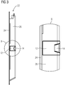
- FIG 3 illustrates a side view of the oven door 22 for the cooking oven 20 according to the preferred embodiment of the present invention.
- the front panel 24 forms the outer side of the oven door 22.
- the door frame 26 of the oven door 22 is attached at the inner side of the front panel 24.
- the door frame 26 is preferably made of plastics.
- the hook seat element 12 is inside the recess of the door frame 26.
- the cross sections of the hook seat element 12 and the door frame 26 have at least partially the same shape, so that the hook seat element 12 forms the integrated part of the door frame 26.
- a detailed side view B in FIG 3 shows the hook seat element 12 and a portion of a vertical part of the door frame 26 by an enlarged scale.
- the detailed side view B clarifies that the hook seat element 12 forms the integrated part of the door frame 26, wherein the shape of the hook seat element 12 is adapted to the shape of the door frame 26.
- the hook seat element 12 is preferably made of plastics.
- the hook seat element 12 is made of the same plastics as the door frame 26.
- the hook seat element 12 may be geometrically and optically adapted to door frame 26.
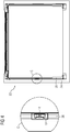
- FIG 4 illustrates a rear view of the oven door 22 for the cooking oven 20 according to the preferred embodiment of the present invention.
- the door frame 26 is attached at the inner side of the front panel 24 of the oven door 22.
- the hook seat element 12 is arranged about at half height of the vertical part of the door frame 26.
- a detailed rear view C in FIG 4 clarifies that the shape of the hook seat element 12 is adapted to the shape of the door frame 26. Further, the hook seat element 12 comprises a bar inside the opening 14 for latching the hook element 10 and the hook seat element 12, wherein the bar penetrates through the clearance hole of hook 16. Thus, the bar inside the opening 14 and the clearance hole of hook 16 form a latching mechanism.
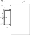
- FIG 5 illustrates a side view of the cooking oven 20 according to the preferred embodiment of the present invention.
- the oven door 22 is in an open state.
- FIG 5 clarifies that the hook seat element 12 is arranged about at half height of the vertical part of the door frame 26. Further, the hook seat element 12 is geometrically and optically adapted to door frame 26.
- the oven door 22 has a compact structure. It is easy to clean the oven door 20.
- the hook element 10 is covered by a side wall of the cooking oven, so that the hook element 10 is invisible for a position lateral of the cooking oven in an open state of the oven door, as depicted in FIG 5 .
- the hook element 10 and the hook seat element 12 allow a vertical centring of the oven door 22 at the oven frame 32, since the hook 16 of the hook seat element 12 and the opening 14 of the hook seat element 12 are angled near the joint zones.
- the hook 16 of the hook seat element 12 and/or the opening 14 of the hook seat element 12 are conical.
- FIG 6 illustrates an exploded perspective rear view of the oven door 22 for the cooking oven 20 according to the preferred embodiment of the present invention.
- FIG 6 clarifies that the hook seat element 12 is installed or installable in the recess of the door frame 26, wherein the cross sections of the hook seat element 12 and the door frame 26 have substantially the same shape, so that the hook seat element 12 forms the integrated part of the door frame 26.
- FIG 6 A detailed perspective view D by an enlarged scale is shown in FIG 6 .
- the hook seat element 12 is fixable in the recess of the door frame 26 by a screw 28, wherein said screws is inserted into door frame 26 from its inner side. This contributed to an easy assembling of the oven door 22 and the cooking oven 20.
- FIG 7 illustrates a perspective view of an oven chassis 30 of the cooking oven 20 according to the preferred embodiment of the present invention.
- the oven frame 32 encloses the oven cavity.
- the hook element 10 is attached at the right vertical part of the oven frame 32, in a fixed position, such that the hook seat element 12 is arranged about at half height of the vertical part of the door frame 26.
- FIG 7 A detailed perspective view E by an enlarged scale is shown in FIG 7 .
- the hook element 10 is fastened by two screws 34 at the right vertical part of the oven frame 32.
- the screws 34 are directed from the outer side to the inner side of the oven frame 32.
- the screws 34 are introduced into the screw holes 18 of the hook element 10.
- closure system according to the present invention is not only provided for the cooking oven 20.
- the closure system with the hook element 10 and the hook seat element 12 may be also installed in other household appliances.
Landscapes
- Engineering & Computer Science (AREA)
- Chemical & Material Sciences (AREA)
- Combustion & Propulsion (AREA)
- Mechanical Engineering (AREA)
- General Engineering & Computer Science (AREA)
- Electric Ovens (AREA)
Abstract
Description
- The present invention relates to a cooking oven including a swing oven door and a closure system for said swing oven door according to the preamble of claim 1.
- A closure system for a swing door of a household appliance is an important device. If the household appliance is an oven, then the closure system must be heat-resistant in order to guarantee the closing and sealing of the oven door. The most closure systems comprise a hook element and a hook seat element, wherein an opening in the hook seat element receives a hook projecting from the hook element. Usually the hook element is assembled at the door, and the hook seat element is placed at a door frame, front frame or chassis of the household appliance. The hook element sticks out from the oven door, which may disturb the user and impairs the security.
-
WO 2007/080146 A2 discloses a closure system comprising the hook seat at the oven frame and the hook at the oven door. However, the mechanism of the hook is complex. -
US 7,735,480 discloses a closure system for two oven doors. The closure system comprises a moveable hook at the oven frame and the hook seat at the oven door. - It is an object of the present invention to provide a cooking oven including a swing door and a closure system for said swing door, wherein said closure system is improved by low complexity.
- The object of the present invention is achieved by the cooking oven including a swing door and a closure system for said swing door according to claim 1.
- According to the present invention the hook element is attached or attachable at an oven frame of an oven chassis, and the hook seat element is attached or attachable at a door frame of an oven door of the cooking oven. There are not any parts at the oven door, which stick out from the dimensions of said oven door. Thus, the oven door has a very compact structure. In particular, there are not any dangerous elements extending from the oven door. Further, it is easy to clean the oven door.
- Preferably, the hook element is arranged at a vertical part of the oven frame.
- In particular, the hook element is arranged at a position of the vertical part of the oven frame such that the hook seat element is arranged about at half height of the vertical part of the door frame.
- Further, the hook element may be covered by a side wall of the cooking oven, so that the hook element is invisible for a position lateral of the cooking oven in an open state of the oven door.
- According to the preferred embodiment of the present invention the hook seat element is inserted or insertable in a recess of the door frame, so that the hook seat element forms an integrated part of the door frame.
- Advantageously, the shape of the hook seat element is adapted to the shape of the door frame. Thus, the hook seat element can be geometrically and optically adapted to the door frame.
- Further, the door frame and the hook seat element are made of the same plastic materials. This supports the optical adaption of the hook seat element to the door frame.
- For example, the hook seat element is fixed or fixable by one screw at the door frame.
- In a similar way, the hook element is fixed or fixable by at least one screw at the oven frame. In particular, the hook element is fixed or fixable by two screws at the oven frame.
- For example, the hook element is made of metal. Alternatively or additionally, the hook element is made of plastics. Thus, the design of the hook element may be adapted to the design of the cooking oven.
- In order to obtain a vertical centring of the oven door, the shape of the opening and/or the shape of the hook may be formed in such way that an automatic vertical centring of the oven door is performed during closing said oven door.
- Further, the opening and/or the hook may have a conical shape, so that the automatic vertical centring of the oven door is performed during closing said oven door.
- At last, the present invention relates to a closure system for a swing oven door of a cooking oven, wherein the closure system is provided for the cooking oven mentioned above.
- The novel and inventive features believed to be the characteristic of the present invention are set forth in the appended claims.
- The invention will be described in further detail with reference to the drawings, in which
- FIG 1
- illustrates an exploded perspective view of a closure system for an oven door of a cooking oven according to a preferred embodiment of the present invention,
- FIG 2
- illustrates a perspective view of the cooking oven according to the preferred embodiment of the present invention,
- FIG 3
- illustrates a side view of the oven door for the cooking oven according the preferred embodiment of the present invention,
- FIG 4
- illustrates a rear view of the oven door for the cooking oven according to the preferred embodiment of the present invention,
- FIG 5
- illustrates a side view of the cooking oven according to the preferred embodiment of the present invention,
- FIG 6
- illustrates an exploded perspective rear view of the oven door for the cooking oven according to the preferred embodiment of the present invention, and
- FIG 7
- illustrates a perspective view of an oven chassis of the cooking oven according to the preferred embodiment of the present invention.
-
FIG 1 illustrates an exploded perspective view of a closure system for anoven door 22 of acooking oven 20 according to a preferred embodiment of the present invention. The closure system includes ahook element 10 and ahook seat element 12. - The
hook element 10 comprises ahook 16 projecting from saidhook element 10. Thehook 16 includes a clearance hole, so that the hook is formed as a bail. Further, thehook element 10 comprises twoscrew holes 18. The screw holes are provided for fastening thehook element 10 in a fixed position at achassis frame 32 of thecooking oven 20. In this example, thehook element 10 is formed as a single-piece part. - The
hook seat element 12 comprises anopening 14 for receiving thehook 16 of thehook element 10. Thehook seat element 12 is provided for adoor frame 26 of theoven door 22. -
FIG 2 illustrates a perspective view of thecooking oven 20 according to the preferred embodiment of the present invention. - The
oven door 22 is arranged at a front side of thecooking oven 20 and is provided for closing an oven cavity. Theoven door 22 is fastened at thecooking oven 20 by at least one hinge-joint arranged at one side of anoven frame 32. In this example, theoven door 22 is fastened at the left hand side of theoven frame 32. Thehook element 10 is fastened at the right hand side of theoven frame 32. Thehook seat element 12 is fastened at the right hand side of theoven door 22. - The
oven door 22 includes afront panel 24 and adoor frame 26. Thefront panel 24 is a plane sheet element and forms the outer side of theoven door 22. Thedoor frame 26 of theoven door 22 is at the inner side of thefront panel 24. Thehook seat element 12 is attached at thedoor frame 26 of the overdoor 22. Thehook seat element 12 is inside a recess of thedoor frame 26, so that thehook seat element 12 forms an integrated part of thedoor frame 26. - In
FIG 2 thehook element 10 and thehook seat element 12 are shown in a detailed perspective view A by an enlarged scale. The detailed perspective view A clarifies that thehook seat element 12 is an integrated part of thedoor frame 26, and thecorresponding hook element 10 is fastened at the right hand side of theoven frame 32. In the closed state of theoven door 22, thehook 16 is received by the opening of thehook seat element 12. -
FIG 3 illustrates a side view of theoven door 22 for thecooking oven 20 according to the preferred embodiment of the present invention. - The
front panel 24 forms the outer side of theoven door 22. Thedoor frame 26 of theoven door 22 is attached at the inner side of thefront panel 24. Thedoor frame 26 is preferably made of plastics. Thehook seat element 12 is inside the recess of thedoor frame 26. The cross sections of thehook seat element 12 and thedoor frame 26 have at least partially the same shape, so that thehook seat element 12 forms the integrated part of thedoor frame 26. - A detailed side view B in
FIG 3 shows thehook seat element 12 and a portion of a vertical part of thedoor frame 26 by an enlarged scale. The detailed side view B clarifies that thehook seat element 12 forms the integrated part of thedoor frame 26, wherein the shape of thehook seat element 12 is adapted to the shape of thedoor frame 26. Further, thehook seat element 12 is preferably made of plastics. In particular, thehook seat element 12 is made of the same plastics as thedoor frame 26. Thus, thehook seat element 12 may be geometrically and optically adapted todoor frame 26. -
FIG 4 illustrates a rear view of theoven door 22 for thecooking oven 20 according to the preferred embodiment of the present invention. Thedoor frame 26 is attached at the inner side of thefront panel 24 of theoven door 22. Thehook seat element 12 is arranged about at half height of the vertical part of thedoor frame 26. - A detailed rear view C in
FIG 4 clarifies that the shape of thehook seat element 12 is adapted to the shape of thedoor frame 26. Further, thehook seat element 12 comprises a bar inside theopening 14 for latching thehook element 10 and thehook seat element 12, wherein the bar penetrates through the clearance hole ofhook 16. Thus, the bar inside theopening 14 and the clearance hole ofhook 16 form a latching mechanism. -
FIG 5 illustrates a side view of thecooking oven 20 according to the preferred embodiment of the present invention. Theoven door 22 is in an open state.FIG 5 clarifies that thehook seat element 12 is arranged about at half height of the vertical part of thedoor frame 26. Further, thehook seat element 12 is geometrically and optically adapted todoor frame 26. - There are no parts at the
oven door 22, which stick out from the dimensions of saidoven door 22. Theoven door 22 has a compact structure. It is easy to clean theoven door 20. In addition, thehook element 10 is covered by a side wall of the cooking oven, so that thehook element 10 is invisible for a position lateral of the cooking oven in an open state of the oven door, as depicted inFIG 5 . - Further, the
hook element 10 and thehook seat element 12 allow a vertical centring of theoven door 22 at theoven frame 32, since thehook 16 of thehook seat element 12 and theopening 14 of thehook seat element 12 are angled near the joint zones. Thehook 16 of thehook seat element 12 and/or theopening 14 of thehook seat element 12 are conical. When theoven door 22 is closed by the user, then theoven door 22 obtains automatically the correct position. Vertical misalignments of theoven door 22 at theoven frame 32 are avoided. -
FIG 6 illustrates an exploded perspective rear view of theoven door 22 for thecooking oven 20 according to the preferred embodiment of the present invention.FIG 6 clarifies that thehook seat element 12 is installed or installable in the recess of thedoor frame 26, wherein the cross sections of thehook seat element 12 and thedoor frame 26 have substantially the same shape, so that thehook seat element 12 forms the integrated part of thedoor frame 26. - A detailed perspective view D by an enlarged scale is shown in
FIG 6 . Thehook seat element 12 is fixable in the recess of thedoor frame 26 by ascrew 28, wherein said screws is inserted intodoor frame 26 from its inner side. This contributed to an easy assembling of theoven door 22 and thecooking oven 20. -
FIG 7 illustrates a perspective view of anoven chassis 30 of thecooking oven 20 according to the preferred embodiment of the present invention. Theoven frame 32 encloses the oven cavity. Thehook element 10 is attached at the right vertical part of theoven frame 32, in a fixed position, such that thehook seat element 12 is arranged about at half height of the vertical part of thedoor frame 26. - A detailed perspective view E by an enlarged scale is shown in
FIG 7 . Thehook element 10 is fastened by twoscrews 34 at the right vertical part of theoven frame 32. Thescrews 34 are directed from the outer side to the inner side of theoven frame 32. Thescrews 34 are introduced into the screw holes 18 of thehook element 10. - The closure system according to the present invention is not only provided for the
cooking oven 20. In general, the closure system with thehook element 10 and thehook seat element 12 may be also installed in other household appliances. - Although an illustrative embodiment of the present invention has been described herein with reference to the accompanying drawings, it is to be understood that the present invention is not limited to that precise embodiment, and that various other changes and modifications may be affected therein by one skilled in the art without departing from the scope of the invention. All such changes and modifications are intended to be included within the scope of the invention as defined by the appended claims.
-
- 10
- hook element
- 12
- hook seat element
- 14
- opening
- 16
- hook
- 18
- screw hole
- 20
- cooking oven
- 22
- oven door
- 24
- front panel
- 26
- door frame
- 28
- screw for the hook seat element
- 30
- oven chassis
- 32
- oven frame
- 34
- screw for the hook element
- A
- detailed perspective view in
FIG 2 - B
- detailed side view in
FIG 3 - C
- detailed rear view in
FIG 4 - D
- detailed perspective view in
FIG 6 - E
- detailed perspective view in
FIG 7
Claims (15)
- A cooking oven (20) including a swing oven door (22) and a closure system (10, 12) for said swing oven door (22), wherein- the closure system comprises a hook element (10) attached or attachable at the cooking oven,- the closure system comprises a hook seat element (12) attached or attachable at the cooking oven,- the hook seat element (12) includes an opening (14) for receiving a hook (16) projecting from the hook element (10), and- the hook element (10) and the hook seat element (12) are detachably connectable by a latching mechanism,
characterized in, that
the hook element (10) is attached or attachable at an oven frame (32) of an oven chassis (30), and the hook seat element (12) is attached or attachable at a door frame (26) of an oven door (22) of the cooking oven (20). - The cooking oven according to claim 1,
characterized in, that
the hook element (10) is arranged at a vertical part of the oven frame (32). - The cooking oven according to claim 1 or 2,
characterized in, that
the hook seat element (12) is arranged at a half height of a vertical part of the door frame (26). - The cooking oven according to any one of the preceding claims,
characterized in, that
the hook element (10) is covered by a side wall of the cooking oven (20), so that the hook element (10) is invisible for a position lateral of the cooking oven (20) in an open state of the oven door (22). - The cooking oven according to any one of the preceding claims,
characterized in, that
the hook seat element (12) is inserted or insertable in a recess of the door frame (26), so that the hook seat element (12) forms an integrated part of the door frame (26). - The cooking oven according to claim 5,
characterized in, that
the shape of the hook seat element (12) is adapted to the shape of the door frame (26). - The cooking oven according to any one of the preceding claims,
characterized in, that
the door frame (26) and the hook seat element (12) are made of the same plastic materials. - The cooking oven according to any one of the preceding claims,
characterized in, that
the hook seat element (12) is fixed or fixable by one screw (28) at the door frame (26). - The cooking oven according to any one of the preceding claims,
characterized in, that
the hook element (10) is fixed or fixable by at least one screw (34) at the oven frame (32). - The cooking oven according to claim 9,
characterized in, that
the hook element (10) is fixed or fixable by two screws (34) at the oven frame (32). - The cooking oven according to any one of the preceding claims,
characterized in, that
the hook element (10) is made of metal. - The cooking oven according to any one of the claims 1 to 10,
characterized in, that
the hook element (10) is made of plastics. - The cooking oven according to any one of the preceding claims,
characterized in, that
the shape of the opening (14) and/or the shape of the hook (16) are formed in such way that an automatic vertical centring of the oven door (22) is performed during closing said oven door (22). - The cooking oven according to claim 13,
characterized in, that
the opening (14) and/or the hook (16) have a conical shape, so that the automatic vertical centring of the oven door (22) is performed during closing said oven door (22). - A closure system for a swing oven door of a cooking oven,
characterized in, that
the closure system is provided for the cooking oven according to any one of the claims 1 to 14.
Priority Applications (1)
| Application Number | Priority Date | Filing Date | Title |
|---|---|---|---|
| EP12158284.5A EP2636957B1 (en) | 2012-03-06 | 2012-03-06 | A cooking oven including a swinging oven door with a closure system of said door |
Applications Claiming Priority (1)
| Application Number | Priority Date | Filing Date | Title |
|---|---|---|---|
| EP12158284.5A EP2636957B1 (en) | 2012-03-06 | 2012-03-06 | A cooking oven including a swinging oven door with a closure system of said door |
Publications (2)
| Publication Number | Publication Date |
|---|---|
| EP2636957A1 true EP2636957A1 (en) | 2013-09-11 |
| EP2636957B1 EP2636957B1 (en) | 2017-10-11 |
Family
ID=45808281
Family Applications (1)
| Application Number | Title | Priority Date | Filing Date |
|---|---|---|---|
| EP12158284.5A Active EP2636957B1 (en) | 2012-03-06 | 2012-03-06 | A cooking oven including a swinging oven door with a closure system of said door |
Country Status (1)
| Country | Link |
|---|---|
| EP (1) | EP2636957B1 (en) |
Cited By (1)
| Publication number | Priority date | Publication date | Assignee | Title |
|---|---|---|---|---|
| EP3388606A1 (en) | 2017-04-14 | 2018-10-17 | Gorenje Gospodinjski aparati d.d. | A door locking device for a household apparatus |
Citations (6)
| Publication number | Priority date | Publication date | Assignee | Title |
|---|---|---|---|---|
| US4960297A (en) * | 1989-09-28 | 1990-10-02 | Component Hardware Group, Inc. | Double action latch |
| EP1469147A2 (en) * | 2003-04-17 | 2004-10-20 | BITRON S.p.A. | A device for locking and unlocking the door of an electric household appliance |
| US20050173932A1 (en) * | 2004-02-09 | 2005-08-11 | Joe Lomicka | Powered latch assembly |
| WO2007080146A2 (en) | 2006-01-10 | 2007-07-19 | BSH Bosch und Siemens Hausgeräte GmbH | Cooking device and method for operating a cooking device |
| US7735480B2 (en) | 2005-08-18 | 2010-06-15 | Maytag Corporation | Door locking mechanism for an oven having French-style doors |
| US20110203332A1 (en) * | 2010-02-25 | 2011-08-25 | Sang-Won Suh | Door lock apparatus |
-
2012
- 2012-03-06 EP EP12158284.5A patent/EP2636957B1/en active Active
Patent Citations (6)
| Publication number | Priority date | Publication date | Assignee | Title |
|---|---|---|---|---|
| US4960297A (en) * | 1989-09-28 | 1990-10-02 | Component Hardware Group, Inc. | Double action latch |
| EP1469147A2 (en) * | 2003-04-17 | 2004-10-20 | BITRON S.p.A. | A device for locking and unlocking the door of an electric household appliance |
| US20050173932A1 (en) * | 2004-02-09 | 2005-08-11 | Joe Lomicka | Powered latch assembly |
| US7735480B2 (en) | 2005-08-18 | 2010-06-15 | Maytag Corporation | Door locking mechanism for an oven having French-style doors |
| WO2007080146A2 (en) | 2006-01-10 | 2007-07-19 | BSH Bosch und Siemens Hausgeräte GmbH | Cooking device and method for operating a cooking device |
| US20110203332A1 (en) * | 2010-02-25 | 2011-08-25 | Sang-Won Suh | Door lock apparatus |
Cited By (1)
| Publication number | Priority date | Publication date | Assignee | Title |
|---|---|---|---|---|
| EP3388606A1 (en) | 2017-04-14 | 2018-10-17 | Gorenje Gospodinjski aparati d.d. | A door locking device for a household apparatus |
Also Published As
| Publication number | Publication date |
|---|---|
| EP2636957B1 (en) | 2017-10-11 |
Similar Documents
| Publication | Publication Date | Title |
|---|---|---|
| EP2225510B1 (en) | Refrigerator | |
| CA2756227C (en) | Door hinge assembly | |
| EP2386702A1 (en) | A door handle for a domestic appliance | |
| US10443857B2 (en) | Cooking appliance | |
| US20150150432A1 (en) | Domestic appliance having a locking arrangement and a door-weight-compensation system | |
| CN106103875B (en) | Household appliance with door damper | |
| EP2400226A1 (en) | Cooking device door | |
| US11072952B2 (en) | Side opening door keeper | |
| US20160195279A1 (en) | Oven appliance | |
| EP2687786A2 (en) | Assembly of a door hinge of an oven of a household appliance with dampened closing | |
| US20210145190A1 (en) | Hinge and dispensing device | |
| US11199331B2 (en) | Cooking oven with cavity drawer having movable door | |
| US11898759B2 (en) | Twist release mechanism for a multi-pane door assembly | |
| US11371715B2 (en) | Cooking appliance comprising a lowerable door, which has a specific retaining spring for a bearing bush | |
| EP2636957B1 (en) | A cooking oven including a swinging oven door with a closure system of said door | |
| KR101898797B1 (en) | Apparatus for supporting shelf and cooking appliance therewith | |
| US5829426A (en) | Apparatus for holding the lid of barbeque grill | |
| WO2010078894A3 (en) | Household appliance, in particular oven | |
| EP2933567B1 (en) | Household cooking appliance | |
| US20170205079A1 (en) | Door for a household appliance, and household appliance having a door | |
| EP3282196A1 (en) | An assembly of a hood and a wall-mounted cabinet | |
| EP2554735A1 (en) | A top-loading washing machine comprising a pivoting lid | |
| US20170284734A1 (en) | Household device having an input means locking device | |
| EP3363978B1 (en) | Sectional door | |
| EP2636956A1 (en) | An oven door for a cooking oven and a method for preparing an oven door for a cooking oven |
Legal Events
| Date | Code | Title | Description |
|---|---|---|---|
| PUAI | Public reference made under article 153(3) epc to a published international application that has entered the european phase |
Free format text: ORIGINAL CODE: 0009012 |
|
| AK | Designated contracting states |
Kind code of ref document: A1 Designated state(s): AL AT BE BG CH CY CZ DE DK EE ES FI FR GB GR HR HU IE IS IT LI LT LU LV MC MK MT NL NO PL PT RO RS SE SI SK SM TR |
|
| AX | Request for extension of the european patent |
Extension state: BA ME |
|
| 17P | Request for examination filed |
Effective date: 20140219 |
|
| RBV | Designated contracting states (corrected) |
Designated state(s): AL AT BE BG CH CY CZ DE DK EE ES FI FR GB GR HR HU IE IS IT LI LT LU LV MC MK MT NL NO PL PT RO RS SE SI SK SM TR |
|
| GRAP | Despatch of communication of intention to grant a patent |
Free format text: ORIGINAL CODE: EPIDOSNIGR1 |
|
| INTG | Intention to grant announced |
Effective date: 20170523 |
|
| GRAS | Grant fee paid |
Free format text: ORIGINAL CODE: EPIDOSNIGR3 |
|
| GRAA | (expected) grant |
Free format text: ORIGINAL CODE: 0009210 |
|
| AK | Designated contracting states |
Kind code of ref document: B1 Designated state(s): AL AT BE BG CH CY CZ DE DK EE ES FI FR GB GR HR HU IE IS IT LI LT LU LV MC MK MT NL NO PL PT RO RS SE SI SK SM TR |
|
| REG | Reference to a national code |
Ref country code: GB Ref legal event code: FG4D |
|
| REG | Reference to a national code |
Ref country code: CH Ref legal event code: EP |
|
| REG | Reference to a national code |
Ref country code: IE Ref legal event code: FG4D |
|
| REG | Reference to a national code |
Ref country code: AT Ref legal event code: REF Ref document number: 936404 Country of ref document: AT Kind code of ref document: T Effective date: 20171115 |
|
| REG | Reference to a national code |
Ref country code: DE Ref legal event code: R096 Ref document number: 602012038305 Country of ref document: DE |
|
| REG | Reference to a national code |
Ref country code: NL Ref legal event code: MP Effective date: 20171011 |
|
| REG | Reference to a national code |
Ref country code: LT Ref legal event code: MG4D |
|
| REG | Reference to a national code |
Ref country code: AT Ref legal event code: MK05 Ref document number: 936404 Country of ref document: AT Kind code of ref document: T Effective date: 20171011 |
|
| REG | Reference to a national code |
Ref country code: FR Ref legal event code: PLFP Year of fee payment: 7 |
|
| PG25 | Lapsed in a contracting state [announced via postgrant information from national office to epo] |
Ref country code: NL Free format text: LAPSE BECAUSE OF FAILURE TO SUBMIT A TRANSLATION OF THE DESCRIPTION OR TO PAY THE FEE WITHIN THE PRESCRIBED TIME-LIMIT Effective date: 20171011 |
|
| PG25 | Lapsed in a contracting state [announced via postgrant information from national office to epo] |
Ref country code: ES Free format text: LAPSE BECAUSE OF FAILURE TO SUBMIT A TRANSLATION OF THE DESCRIPTION OR TO PAY THE FEE WITHIN THE PRESCRIBED TIME-LIMIT Effective date: 20171011 Ref country code: FI Free format text: LAPSE BECAUSE OF FAILURE TO SUBMIT A TRANSLATION OF THE DESCRIPTION OR TO PAY THE FEE WITHIN THE PRESCRIBED TIME-LIMIT Effective date: 20171011 Ref country code: SE Free format text: LAPSE BECAUSE OF FAILURE TO SUBMIT A TRANSLATION OF THE DESCRIPTION OR TO PAY THE FEE WITHIN THE PRESCRIBED TIME-LIMIT Effective date: 20171011 Ref country code: LT Free format text: LAPSE BECAUSE OF FAILURE TO SUBMIT A TRANSLATION OF THE DESCRIPTION OR TO PAY THE FEE WITHIN THE PRESCRIBED TIME-LIMIT Effective date: 20171011 Ref country code: NO Free format text: LAPSE BECAUSE OF FAILURE TO SUBMIT A TRANSLATION OF THE DESCRIPTION OR TO PAY THE FEE WITHIN THE PRESCRIBED TIME-LIMIT Effective date: 20180111 |
|
| PG25 | Lapsed in a contracting state [announced via postgrant information from national office to epo] |
Ref country code: AT Free format text: LAPSE BECAUSE OF FAILURE TO SUBMIT A TRANSLATION OF THE DESCRIPTION OR TO PAY THE FEE WITHIN THE PRESCRIBED TIME-LIMIT Effective date: 20171011 Ref country code: GR Free format text: LAPSE BECAUSE OF FAILURE TO SUBMIT A TRANSLATION OF THE DESCRIPTION OR TO PAY THE FEE WITHIN THE PRESCRIBED TIME-LIMIT Effective date: 20180112 Ref country code: BG Free format text: LAPSE BECAUSE OF FAILURE TO SUBMIT A TRANSLATION OF THE DESCRIPTION OR TO PAY THE FEE WITHIN THE PRESCRIBED TIME-LIMIT Effective date: 20180111 Ref country code: RS Free format text: LAPSE BECAUSE OF FAILURE TO SUBMIT A TRANSLATION OF THE DESCRIPTION OR TO PAY THE FEE WITHIN THE PRESCRIBED TIME-LIMIT Effective date: 20171011 Ref country code: LV Free format text: LAPSE BECAUSE OF FAILURE TO SUBMIT A TRANSLATION OF THE DESCRIPTION OR TO PAY THE FEE WITHIN THE PRESCRIBED TIME-LIMIT Effective date: 20171011 Ref country code: HR Free format text: LAPSE BECAUSE OF FAILURE TO SUBMIT A TRANSLATION OF THE DESCRIPTION OR TO PAY THE FEE WITHIN THE PRESCRIBED TIME-LIMIT Effective date: 20171011 Ref country code: IS Free format text: LAPSE BECAUSE OF FAILURE TO SUBMIT A TRANSLATION OF THE DESCRIPTION OR TO PAY THE FEE WITHIN THE PRESCRIBED TIME-LIMIT Effective date: 20180211 |
|
| REG | Reference to a national code |
Ref country code: DE Ref legal event code: R097 Ref document number: 602012038305 Country of ref document: DE |
|
| PG25 | Lapsed in a contracting state [announced via postgrant information from national office to epo] |
Ref country code: CZ Free format text: LAPSE BECAUSE OF FAILURE TO SUBMIT A TRANSLATION OF THE DESCRIPTION OR TO PAY THE FEE WITHIN THE PRESCRIBED TIME-LIMIT Effective date: 20171011 Ref country code: SK Free format text: LAPSE BECAUSE OF FAILURE TO SUBMIT A TRANSLATION OF THE DESCRIPTION OR TO PAY THE FEE WITHIN THE PRESCRIBED TIME-LIMIT Effective date: 20171011 Ref country code: EE Free format text: LAPSE BECAUSE OF FAILURE TO SUBMIT A TRANSLATION OF THE DESCRIPTION OR TO PAY THE FEE WITHIN THE PRESCRIBED TIME-LIMIT Effective date: 20171011 Ref country code: DK Free format text: LAPSE BECAUSE OF FAILURE TO SUBMIT A TRANSLATION OF THE DESCRIPTION OR TO PAY THE FEE WITHIN THE PRESCRIBED TIME-LIMIT Effective date: 20171011 |
|
| PLBE | No opposition filed within time limit |
Free format text: ORIGINAL CODE: 0009261 |
|
| STAA | Information on the status of an ep patent application or granted ep patent |
Free format text: STATUS: NO OPPOSITION FILED WITHIN TIME LIMIT |
|
| PG25 | Lapsed in a contracting state [announced via postgrant information from national office to epo] |
Ref country code: PL Free format text: LAPSE BECAUSE OF FAILURE TO SUBMIT A TRANSLATION OF THE DESCRIPTION OR TO PAY THE FEE WITHIN THE PRESCRIBED TIME-LIMIT Effective date: 20171011 Ref country code: SM Free format text: LAPSE BECAUSE OF FAILURE TO SUBMIT A TRANSLATION OF THE DESCRIPTION OR TO PAY THE FEE WITHIN THE PRESCRIBED TIME-LIMIT Effective date: 20171011 Ref country code: RO Free format text: LAPSE BECAUSE OF FAILURE TO SUBMIT A TRANSLATION OF THE DESCRIPTION OR TO PAY THE FEE WITHIN THE PRESCRIBED TIME-LIMIT Effective date: 20171011 |
|
| 26N | No opposition filed |
Effective date: 20180712 |
|
| REG | Reference to a national code |
Ref country code: CH Ref legal event code: PL |
|
| PG25 | Lapsed in a contracting state [announced via postgrant information from national office to epo] |
Ref country code: MC Free format text: LAPSE BECAUSE OF FAILURE TO SUBMIT A TRANSLATION OF THE DESCRIPTION OR TO PAY THE FEE WITHIN THE PRESCRIBED TIME-LIMIT Effective date: 20171011 Ref country code: SI Free format text: LAPSE BECAUSE OF FAILURE TO SUBMIT A TRANSLATION OF THE DESCRIPTION OR TO PAY THE FEE WITHIN THE PRESCRIBED TIME-LIMIT Effective date: 20171011 |
|
| REG | Reference to a national code |
Ref country code: BE Ref legal event code: MM Effective date: 20180331 |
|
| REG | Reference to a national code |
Ref country code: IE Ref legal event code: MM4A |
|
| PG25 | Lapsed in a contracting state [announced via postgrant information from national office to epo] |
Ref country code: LU Free format text: LAPSE BECAUSE OF NON-PAYMENT OF DUE FEES Effective date: 20180306 |
|
| PG25 | Lapsed in a contracting state [announced via postgrant information from national office to epo] |
Ref country code: IE Free format text: LAPSE BECAUSE OF NON-PAYMENT OF DUE FEES Effective date: 20180306 |
|
| PG25 | Lapsed in a contracting state [announced via postgrant information from national office to epo] |
Ref country code: LI Free format text: LAPSE BECAUSE OF NON-PAYMENT OF DUE FEES Effective date: 20180331 Ref country code: CH Free format text: LAPSE BECAUSE OF NON-PAYMENT OF DUE FEES Effective date: 20180331 Ref country code: BE Free format text: LAPSE BECAUSE OF NON-PAYMENT OF DUE FEES Effective date: 20180331 |
|
| PG25 | Lapsed in a contracting state [announced via postgrant information from national office to epo] |
Ref country code: MT Free format text: LAPSE BECAUSE OF NON-PAYMENT OF DUE FEES Effective date: 20180306 |
|
| PG25 | Lapsed in a contracting state [announced via postgrant information from national office to epo] |
Ref country code: TR Free format text: LAPSE BECAUSE OF FAILURE TO SUBMIT A TRANSLATION OF THE DESCRIPTION OR TO PAY THE FEE WITHIN THE PRESCRIBED TIME-LIMIT Effective date: 20171011 |
|
| PG25 | Lapsed in a contracting state [announced via postgrant information from national office to epo] |
Ref country code: PT Free format text: LAPSE BECAUSE OF FAILURE TO SUBMIT A TRANSLATION OF THE DESCRIPTION OR TO PAY THE FEE WITHIN THE PRESCRIBED TIME-LIMIT Effective date: 20171011 Ref country code: HU Free format text: LAPSE BECAUSE OF FAILURE TO SUBMIT A TRANSLATION OF THE DESCRIPTION OR TO PAY THE FEE WITHIN THE PRESCRIBED TIME-LIMIT; INVALID AB INITIO Effective date: 20120306 |
|
| PG25 | Lapsed in a contracting state [announced via postgrant information from national office to epo] |
Ref country code: MK Free format text: LAPSE BECAUSE OF NON-PAYMENT OF DUE FEES Effective date: 20171011 Ref country code: CY Free format text: LAPSE BECAUSE OF FAILURE TO SUBMIT A TRANSLATION OF THE DESCRIPTION OR TO PAY THE FEE WITHIN THE PRESCRIBED TIME-LIMIT Effective date: 20171011 |
|
| PG25 | Lapsed in a contracting state [announced via postgrant information from national office to epo] |
Ref country code: AL Free format text: LAPSE BECAUSE OF FAILURE TO SUBMIT A TRANSLATION OF THE DESCRIPTION OR TO PAY THE FEE WITHIN THE PRESCRIBED TIME-LIMIT Effective date: 20171011 |
|
| P01 | Opt-out of the competence of the unified patent court (upc) registered |
Effective date: 20230625 |
|
| PGFP | Annual fee paid to national office [announced via postgrant information from national office to epo] |
Ref country code: DE Payment date: 20250327 Year of fee payment: 14 |
|
| PGFP | Annual fee paid to national office [announced via postgrant information from national office to epo] |
Ref country code: FR Payment date: 20250324 Year of fee payment: 14 |
|
| PGFP | Annual fee paid to national office [announced via postgrant information from national office to epo] |
Ref country code: IT Payment date: 20250321 Year of fee payment: 14 Ref country code: GB Payment date: 20250325 Year of fee payment: 14 |