EP2634523A1 - Dispositif de visée pour armes à feu, arme à feu et procédé d'alignement d'une arme à feu - Google Patents
Dispositif de visée pour armes à feu, arme à feu et procédé d'alignement d'une arme à feu Download PDFInfo
- Publication number
- EP2634523A1 EP2634523A1 EP13002726.1A EP13002726A EP2634523A1 EP 2634523 A1 EP2634523 A1 EP 2634523A1 EP 13002726 A EP13002726 A EP 13002726A EP 2634523 A1 EP2634523 A1 EP 2634523A1
- Authority
- EP
- European Patent Office
- Prior art keywords
- firearm
- image
- target object
- target
- control computer
- Prior art date
- Legal status (The legal status is an assumption and is not a legal conclusion. Google has not performed a legal analysis and makes no representation as to the accuracy of the status listed.)
- Granted
Links
Images


Classifications
-
- F—MECHANICAL ENGINEERING; LIGHTING; HEATING; WEAPONS; BLASTING
- F41—WEAPONS
- F41G—WEAPON SIGHTS; AIMING
- F41G3/00—Aiming or laying means
- F41G3/06—Aiming or laying means with rangefinder
-
- F—MECHANICAL ENGINEERING; LIGHTING; HEATING; WEAPONS; BLASTING
- F41—WEAPONS
- F41G—WEAPON SIGHTS; AIMING
- F41G1/00—Sighting devices
- F41G1/46—Sighting devices for particular applications
- F41G1/48—Sighting devices for particular applications for firing grenades from rifles
-
- F—MECHANICAL ENGINEERING; LIGHTING; HEATING; WEAPONS; BLASTING
- F41—WEAPONS
- F41G—WEAPON SIGHTS; AIMING
- F41G3/00—Aiming or laying means
- F41G3/14—Indirect aiming means
- F41G3/16—Sighting devices adapted for indirect laying of fire
- F41G3/165—Sighting devices adapted for indirect laying of fire using a TV-monitor
Definitions
- the present invention relates to a firearm aiming device. It further relates to a firearm with a projectile leading barrel and such a target device. Finally, the patent application also relates to a method for aligning a firearm equipped with the firearm aiming device.
- the object of the present invention is therefore to specify a firearm targeting device and a firearm having this target device, by means of which the aiming process is facilitated and accelerated for the shooter of a ballistic projectile.
- the aiming device of the object is achieved by a firearm aiming device with the features of claim 1.
- This firearm aiming device according to the invention is provided with an image detecting device, a distance measuring device, an inertial measuring unit, a control computer and an image display device.
- Such a trained firearm target device makes it possible to assist the shooter in the form of a target assistant in reliable sighting of a target object to find the optimal launching angle for a given ammunition, so for a given projectile, and for a determined distance.
- an image capture device designed, for example, as a high-resolution digital camera and an image display device connected thereto, the shooter can keep the target in the field of view from the start of the target process until the shot is fired. If the camera is equipped with a zoom device, the shooter can even aim the target object precisely and thereby precisely determine the impact point of the projectile.
- the directed to the firearm part of the object is achieved by the firearm specified in claim 2.
- the control computer is configured to display an image of a target object picked up by the image capturing means on the image reproducing apparatus such that the image of the target object is then in registration with a sighting mark when the elevation angle of the barrel axis is the pitch angle of the projectile trajectory to the target object calculated by the control computer in accordance with the direction to the target object and the distance to the target object determined by the rangefinder and taking into account weapon and projectile parameters equivalent.
- the projectile trajectory is calculated by the control computer after the distance to the targeted target object has been determined by means of the distance measuring device and the direction to the target object has been determined.
- This firearm according to the invention which is provided with a target device according to the invention, allows a fast and precise sighting of a target object and an alignment of the barrel of the firearm, taking into account the expected ballistic trajectory of the projectile. But not only this substantially vertical orientation of the firearm, but also a tracking of a moving target in the horizontal direction by means of this firearm according to the invention quickly and easily possible, without thereby diminishing the target precision.
- the optical axis of the distance measuring device preferably runs parallel to the running axis. This makes it possible to align the barrel of the firearm already in the distance measurement directly to the target, so that when no ballistic correction is required, can be fired immediately to the target.
- the optical axis of the image capture device is inclined downwards with respect to the barrel axis. This ensures that when aligning the barrel of the firearm upwards, ie when the projectile flies on a clearly curved ballistic trajectory, the image capture device, so for example the digital video camera, always located on a large section of between the shooter and the target object Ground area is directed so that the shooter can observe this floor area on the image display device even when the firearm is tilted upwards.
- the shooter is guided through the sighting process, the control computer of the firearm aiming device according to the invention, with a process program running thereon, forming a target assistant for the shooter.
- the shooter is intuitively guided through the entire aiming process until he has precisely targeted the target and can fire the weapon.
- the displacement of the overlap of the sighting mark with the image separation in step f) takes place in such a way that the image detail recorded by the image capture device and reproduced on the image reproduction device is displaced.
- the shooter is intuitively stimulated by moving the image section to align the firearm in this way to incline upward, for example, that the originally targeted target object remains in the sighting mark fixed on the image display device.
- the displacement of the overlap of the sighting mark with the image detail in step f) can also take place in such a way that the sighting mark displayed on the image reproduction device is displaced.
- the shooter is intuitively stimulated by the automatic shifting of the sighting mark, to change the orientation of the weapon in such a way that the sighting mark remains in registration with the image of the target object displayed on the image display device or recovers in overlap.
- At least one direction symbol is displayed by the control computer in the image displayed on the image display device is displayed, which indicates to the shooter, in which direction he must move the firearm to bring the originally targeted target after the shift occurring in step d) again with the sighting mark in overlap.
- This display of a directional symbol accelerates the reaction of the shooter and may be particularly advantageous if due to a very dark image or strong sunlight on the image display device, the recognizability of the target object on the image display device is difficult.
- At least one symbol is displayed by the control computer in the image displayed on the image display device, which gives the shooter an indication of how he has to rotate the firearm around the barrel axis so that the calculated projectile trajectory hits the targeted target object.
- This twist indicator is useful if the shooter does not keep the firearm precisely aligned in the vertical direction. He is prompted by this twist display to bring about the optimal vertical alignment of the firearm before triggering the firearm.
- control computer displays at least one optical signal in the image displayed on the image display device and / or emits an acoustic signal when the projectile trajectory calculated by the control computer strikes the target object. If such an optical or acoustic signal is perceived by the shooter, he knows that he can press the trigger of the firearm at this moment to hit the target precisely.
- a firearm aiming device 1 according to the invention is shown, which is mounted on the barrel 20 of a firearm 2.
- the firearm 2 is formed in the example shown by a grenade gun whose barrel 20 is a launcher for a ballistic projectile, such as a rifle grenade (not shown), forms.
- the barrel 20 has a barrel axis 22, which is also referred to below as the thrower axis.
- the components of the firearm aiming device 1 are shown schematically in FIG Fig. 2 shown.
- the firearm aiming device 1 is provided with an image capture device 10, which is shown in the example shown as a high-resolution video camera, a distance measuring device 12, which is formed in the example shown by a laser rangefinder, an inertial measurement unit (IMU) 14, a control computer 16 and a Image reproduction device 18.
- the image acquisition device 10, the distance measuring device 12, the inertial measurement unit 14 and the image reproduction device 18 are connected via corresponding data lines 11, 13, 15, 17 to the control computer 16 for data transmission.
- the trigger lever 24 of the firearm 2 is connected via a data line 19 to the control computer 16.
- the components of the firearms targeting device 1 listed above are - except for the image display device 18 - accommodated in a housing 1 ', which can be mounted on the frame of the firearm 2.
- the orientation of the distance measuring device 12 is such that the axis 12 'of the distance measuring device 12 extends parallel to the running axis 22.
- the optical axis 10 'of the image sensing device 10 is oriented so as to be inclined downward with respect to the optical axis 12' of the distance measuring device 12 and the running axis 22, as in FIG Fig. 1 can be seen.
- the image display device 18 may be formed by an attachable to the housing 1 'or on the housing 1' attachable display, such as a transflexive display, or the image display device 18 may be attached to the helmet of the shooter display, which via cable or wirelessly with the Firearms aiming device is connected.
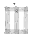
- Fig. 3A shows a first position of the attached to the firearm 2 firearms target device 1, which is symbolized here only by the image capture device 10 shown as a camera.
- the firearm aiming device 1 is with its line of sight V, which corresponds to the axis 12 'of the distance measuring device 12, directed to a target object Z, which is shown in the example as a vehicle.
- the optical axis 10 'of the image capture device 10 which bisects the angle of view ⁇ of the image capture device 10, is inclined downward relative to the line of sight 12'.
- the image capture device 10 or its sensor is mounted slightly inclined downwards. For example, if the camera has an opening angle of ⁇ 20 °, it will be installed at a slope of about 15 ° downwards.
- a sighting window 3 is shown, which has a crosshair 30 in the middle.
- the sighting window 3 also has horizontal arrows 32 which point in opposite directions and which form an indicator for an azimuth deviation.
- vertical arrows 34 are shown in the sighting window, which form an indicator for an elevation deviation.
- the sighting window 3 is superimposed on the shooter in the image of the target object Z recorded by the image capture device 10 and reproduced on the image reproduction device 18.
- the sighting window 3 can frame a part of the image displayed on the image display device 18 or can correspond to the entire screen of the image display device 18.
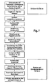
- the axis 12 'of the distance measuring device 12 is directed at the target object Z, so that the distance between the firearm target device 1, that is the position of the shooter, and the target object Z can be determined.
- This distance determination is carried out after lightly touching the trigger 24 of the firearm 2, which sends a start signal for the distance measurement to the control computer 16 via the data power 19.
- the position and position of the firearm aiming device 1 are determined by means of the inertial measuring unit 14.
- the shooter in the extension of the Werferrohrachse lying image detail is shown together with a crosshair as a sighting mark 30 in the sighting window 3 on the image display device 18 first.
- the trigger lever (trigger) 24 By slightly operating the trigger lever (trigger) 24, the distance measurement is started and the distance determined by the laser range finder 12 is read out and stored in a data memory.
- the position angle determined by the inertial measurement unit (IMU) 14 of the firearm target device 1 and thus the firearm 2 is read out and likewise stored in a memory of the control computer 16.
- IMU inertial measurement unit
- the laser rangefinder 12 collinear, that is parallel to the thrower axis 22 is mounted, the height of the target Z is compared to the position of the shooter determined by means of the inertial measuring unit 14 at the same time.
- the target elevation angle and stored in a memory of the control computer 16 weapons and Geschosparametern the firing angle, ie the elevation angle ⁇ calculated that is required to guide the projectile on its ballistic trajectory to the goal Z.
- This shooting angle ⁇ is in Fig. 3B shown as angle ⁇ between the horizontal H and the thrower axis 22.
- the image detail read out from the sensor of the image capture device 10 is shifted by a number of lines corresponding to the shooting angle ⁇ , as in FIG Fig. 3B symbolically represented by the arrow P.
- a pixel line corresponds to a weft angle difference of 0.01 °.
- Fig. 3B the original image section with the target object Z is shown dashed as a sighting window 3, as shown in the in Fig. 3A shown positioning of the firearm target device 1 has been positioned relative to the angle of view ⁇ of the image capture device 10. After moving the image section, this image section takes the position 3 'and the shooter must be provided with the firearm target device 1 firearm 2 to the in Fig. 3B bring shown inclination position so that the target object Z is again in the reticule 30.
- the shooter is also indicated via horizontal arrow symbols 32, in which azimuth direction he has to pivot the firearm 2 laterally in order to move the crosshair 30 into the in-dash Fig. 3A targeted target Z to bring. If the target object Z moves, the shooter can track it with the aid of the horizontal arrows 32 displayed to him and thus keep the crosshairs in the original position of the target object.
- the visual control and tracking of the azimuth also has the advantage of being independent of circular drift or magnetic field interference.
- Vertical arrow symbols 34 indicate to the shooter whether he should keep the firearm 2 steeper or shallower. Furthermore, it is displayed on curved or circular arrow representations 36, whether he is the rolling position of the firearm. 2 must change, so the firearm 2 must rotate about the barrel axis or Werwerse 22.
- the optimum shooting angle ⁇ is reached, this is communicated to the shooter by an optical signal on the display of the image display device 18 and / or an acoustic signal. This optimum shooting angle is achieved when the displayed crosshair is again in the same place on the target Z as in Fig. 3A ,
- This shooting angle is measured accurately by means of the inertial measuring unit IMU 14 and the shooter is informed when reaching the optimum shooting angle by an indicator in the display of the image display device 18, for example by a green field, that the optimum shooting angle has been achieved.
- the contactor can thus always check whether the crosshair position calculated on the basis of the line shift and the shot angle position calculated by the IMU 14 inertial measurement unit (green light in the display) provide consistent data, so that the contactor has a redundant system, which offers safety advantages.
- the device according to the invention may also assume other than the above-described embodiments.
- the device may in particular have features that represent a combination of the respective individual features of the claims.
Landscapes
- Engineering & Computer Science (AREA)
- General Engineering & Computer Science (AREA)
- Physics & Mathematics (AREA)
- Optics & Photonics (AREA)
- Aiming, Guidance, Guns With A Light Source, Armor, Camouflage, And Targets (AREA)
Applications Claiming Priority (2)
| Application Number | Priority Date | Filing Date | Title |
|---|---|---|---|
| DE102011018947A DE102011018947A1 (de) | 2011-04-29 | 2011-04-29 | Schusswaffen-Zielvorrichtung und Schusswaffe sowie Verfahren zum Ausrichten einer Schusswaffe |
| EP12002584.6A EP2518432B1 (fr) | 2011-04-29 | 2012-04-12 | Dispositif de visée pour armes à feu, arme à feu et procédé d'alignement d'une arme à feu |
Related Parent Applications (3)
| Application Number | Title | Priority Date | Filing Date |
|---|---|---|---|
| EP12002584.6A Division-Into EP2518432B1 (fr) | 2011-04-29 | 2012-04-12 | Dispositif de visée pour armes à feu, arme à feu et procédé d'alignement d'une arme à feu |
| EP12002584.6A Division EP2518432B1 (fr) | 2011-04-29 | 2012-04-12 | Dispositif de visée pour armes à feu, arme à feu et procédé d'alignement d'une arme à feu |
| EP12002584.6 Division | 2012-04-12 |
Publications (2)
| Publication Number | Publication Date |
|---|---|
| EP2634523A1 true EP2634523A1 (fr) | 2013-09-04 |
| EP2634523B1 EP2634523B1 (fr) | 2019-09-11 |
Family
ID=45992023
Family Applications (2)
| Application Number | Title | Priority Date | Filing Date |
|---|---|---|---|
| EP13002726.1A Active EP2634523B1 (fr) | 2011-04-29 | 2012-04-12 | Dispositif de visée pour armes à feu, arme à feu et procédé d'alignement d'une arme à feu |
| EP12002584.6A Active EP2518432B1 (fr) | 2011-04-29 | 2012-04-12 | Dispositif de visée pour armes à feu, arme à feu et procédé d'alignement d'une arme à feu |
Family Applications After (1)
| Application Number | Title | Priority Date | Filing Date |
|---|---|---|---|
| EP12002584.6A Active EP2518432B1 (fr) | 2011-04-29 | 2012-04-12 | Dispositif de visée pour armes à feu, arme à feu et procédé d'alignement d'une arme à feu |
Country Status (4)
| Country | Link |
|---|---|
| EP (2) | EP2634523B1 (fr) |
| DE (1) | DE102011018947A1 (fr) |
| ES (2) | ES2669544T3 (fr) |
| PL (1) | PL2518432T3 (fr) |
Families Citing this family (11)
| Publication number | Priority date | Publication date | Assignee | Title |
|---|---|---|---|---|
| US8833655B2 (en) | 2011-05-26 | 2014-09-16 | Burris Corporation | Magnification compensating sighting systems and methods |
| DE102011105303A1 (de) | 2011-06-22 | 2012-12-27 | Diehl Bgt Defence Gmbh & Co. Kg | Feuerleiteinrichtung |
| TWI633272B (zh) | 2012-02-04 | 2018-08-21 | 伯里斯公司 | 瞄準系統 |
| US9250036B2 (en) | 2012-03-05 | 2016-02-02 | Burris Company, Inc. | Optical device utilizing ballistic zoom and methods for sighting a target |
| DE102013014619A1 (de) * | 2013-09-04 | 2015-03-05 | Rheinmetall Soldier Electronics Gmbh | Zielmittel für Handfeuerwaffen und Handfeuerwaffen mit dem Zielmittel sowie Justage des Zielmittels |
| RU2674720C2 (ru) * | 2014-02-07 | 2018-12-12 | Баррис Компани, Инк. | Оптическое устройство, использующее баллистическое масштабирование, и способ визирования цели (варианты) |
| FR3022337B1 (fr) * | 2014-06-13 | 2018-08-03 | Gael Guillerm | Procedes et systemes d'assistance a la visee d'une cible pour arme, en particulier pour lanceur de defense |
| US9423215B2 (en) | 2014-11-26 | 2016-08-23 | Burris Corporation | Multi-turn elevation knob for optical device |
| US10415934B2 (en) | 2015-02-27 | 2019-09-17 | Burris Company, Inc. | Self-aligning optical sight mount |
| CN111272014B (zh) * | 2019-12-31 | 2022-05-31 | 北京晶品特装科技股份有限公司 | 一种基于动态标尺的火控解算控制系统及方法 |
| FR3120938B1 (fr) * | 2021-03-22 | 2023-09-08 | Thales Sa | Procede d'aide au tir sur une cible mobile, dispositif et ensemble associes |
Citations (6)
| Publication number | Priority date | Publication date | Assignee | Title |
|---|---|---|---|---|
| US5456157A (en) * | 1992-12-02 | 1995-10-10 | Computing Devices Canada Ltd. | Weapon aiming system |
| EP0785406A2 (fr) * | 1996-01-22 | 1997-07-23 | HE HOLDINGS, INC. dba HUGHES ELECTRONICS | Procédé et dispositif de conduite de tir d'une arme à trajectoire à haute apogée |
| US6499382B1 (en) * | 1998-08-24 | 2002-12-31 | General Dynamics Canada Ltd. | Aiming system for weapon capable of superelevation |
| US6873406B1 (en) * | 2002-01-11 | 2005-03-29 | Opti-Logic Corporation | Tilt-compensated laser rangefinder |
| US20050268521A1 (en) * | 2004-06-07 | 2005-12-08 | Raytheon Company | Electronic sight for firearm, and method of operating same |
| US20070137088A1 (en) * | 2005-11-01 | 2007-06-21 | Leupold & Stevens, Inc. | Ballistic ranging methods and systems for inclined shooting |
Family Cites Families (2)
| Publication number | Priority date | Publication date | Assignee | Title |
|---|---|---|---|---|
| DK1304539T3 (da) * | 2001-10-12 | 2005-12-12 | Contraves Ag | Fremgangsmåde og indretning til indstilling af et våbenlöb og anvendelse af indretningen |
| US20050241207A1 (en) * | 2004-03-10 | 2005-11-03 | Raytheon Company, A Corporation Of The State Of Delaware | Common aperture time-division-multiplexed laser rangefinder |
-
2011
- 2011-04-29 DE DE102011018947A patent/DE102011018947A1/de not_active Ceased
-
2012
- 2012-04-12 PL PL12002584T patent/PL2518432T3/pl unknown
- 2012-04-12 EP EP13002726.1A patent/EP2634523B1/fr active Active
- 2012-04-12 EP EP12002584.6A patent/EP2518432B1/fr active Active
- 2012-04-12 ES ES12002584.6T patent/ES2669544T3/es active Active
- 2012-04-12 ES ES13002726T patent/ES2753184T3/es active Active
Patent Citations (6)
| Publication number | Priority date | Publication date | Assignee | Title |
|---|---|---|---|---|
| US5456157A (en) * | 1992-12-02 | 1995-10-10 | Computing Devices Canada Ltd. | Weapon aiming system |
| EP0785406A2 (fr) * | 1996-01-22 | 1997-07-23 | HE HOLDINGS, INC. dba HUGHES ELECTRONICS | Procédé et dispositif de conduite de tir d'une arme à trajectoire à haute apogée |
| US6499382B1 (en) * | 1998-08-24 | 2002-12-31 | General Dynamics Canada Ltd. | Aiming system for weapon capable of superelevation |
| US6873406B1 (en) * | 2002-01-11 | 2005-03-29 | Opti-Logic Corporation | Tilt-compensated laser rangefinder |
| US20050268521A1 (en) * | 2004-06-07 | 2005-12-08 | Raytheon Company | Electronic sight for firearm, and method of operating same |
| US20070137088A1 (en) * | 2005-11-01 | 2007-06-21 | Leupold & Stevens, Inc. | Ballistic ranging methods and systems for inclined shooting |
Also Published As
| Publication number | Publication date |
|---|---|
| DE102011018947A1 (de) | 2012-10-31 |
| EP2518432A1 (fr) | 2012-10-31 |
| EP2518432B1 (fr) | 2018-03-28 |
| PL2518432T3 (pl) | 2018-09-28 |
| EP2634523B1 (fr) | 2019-09-11 |
| ES2669544T3 (es) | 2018-05-28 |
| ES2753184T3 (es) | 2020-04-07 |
Similar Documents
| Publication | Publication Date | Title |
|---|---|---|
| EP2634523B1 (fr) | Dispositif de visée pour armes à feu, arme à feu et procédé d'alignement d'une arme à feu | |
| EP1859221B1 (fr) | Systeme de cible destine a une arme a feu | |
| EP1304539B1 (fr) | Procédé et dispositif pour pointer un tube de cannon et utilisation du dispositif | |
| EP2878913B1 (fr) | Appareil de viser à conduite de tir, arme à feu avec un tel appareil de viser et procédé d'alignement de cette arme à feu | |
| EP2275769B1 (fr) | Appareil de conduite de tir pour une arme à feu | |
| DE102005007910A1 (de) | Feuerwaffe für langsam fliegende Geschosse | |
| DE19719977C1 (de) | Video-Visier mit integrierter Feuerleitung für Gewehre | |
| EP1314949B1 (fr) | Procédé et dispositif pour l'évaluation des erreurs de pointage d'un système d'arme et utilisation du procédé | |
| KR20120064429A (ko) | 무장 시스템 및 무장 유니트의 제어방법 | |
| EP3150956A1 (fr) | Systeme de controle de tir pour une arme de poing et arme de poing | |
| EP1314950B1 (fr) | Procédé et dispositif pour l'évaluation des erreurs de pointage d'un système d'arme et utilisation du procédé | |
| DE1951622C3 (de) | Anordnung zur simulierten Darstellung von Schußbahnen | |
| DE102014019200A1 (de) | Maschinenwaffe | |
| EP3034983B1 (fr) | Pistolet automatique | |
| DE102008015423A1 (de) | Visier mit Zielsicht für Waffen insbesondere mit Munition für gestreckte oder überhöhte Flugbahnen | |
| DE4111935C2 (fr) | ||
| EP3350536B1 (fr) | Tourelle téléopérée et procédé de commande d'une tourelle téléopérée | |
| DE318160C (fr) | ||
| DE102005021044A1 (de) | Zielkamera | |
| DE102011107950A1 (de) | System von Waffen | |
| DE19806911C2 (de) | Verfahren zur Überwachung der Ausichtung einer Artilleriewaffe | |
| DE1266179B (de) | Anlage zur Ausbildung von Richt- und Lenkschuetzen | |
| DE19935816C2 (de) | Automatisches System zur Eichung von Zieleinrichtungen (-fernrohren) auf Gewehren mittels Laserstrahl und Stellmotoren | |
| WO2023042195A1 (fr) | Dispositif de visée intelligent avec système d'entraînement intégré pour le tir d'élite et l'utilisation d'une arme à feu | |
| RU2436029C1 (ru) | Способ визирования |
Legal Events
| Date | Code | Title | Description |
|---|---|---|---|
| PUAI | Public reference made under article 153(3) epc to a published international application that has entered the european phase |
Free format text: ORIGINAL CODE: 0009012 |
|
| AC | Divisional application: reference to earlier application |
Ref document number: 2518432 Country of ref document: EP Kind code of ref document: P |
|
| AK | Designated contracting states |
Kind code of ref document: A1 Designated state(s): AL AT BE BG CH CY CZ DE DK EE ES FI FR GB GR HR HU IE IS IT LI LT LU LV MC MK MT NL NO PL PT RO RS SE SI SK SM TR |
|
| AX | Request for extension of the european patent |
Extension state: BA ME |
|
| 17P | Request for examination filed |
Effective date: 20140211 |
|
| STAA | Information on the status of an ep patent application or granted ep patent |
Free format text: STATUS: EXAMINATION IS IN PROGRESS |
|
| 17Q | First examination report despatched |
Effective date: 20170712 |
|
| GRAP | Despatch of communication of intention to grant a patent |
Free format text: ORIGINAL CODE: EPIDOSNIGR1 |
|
| STAA | Information on the status of an ep patent application or granted ep patent |
Free format text: STATUS: GRANT OF PATENT IS INTENDED |
|
| INTG | Intention to grant announced |
Effective date: 20190403 |
|
| RIN1 | Information on inventor provided before grant (corrected) |
Inventor name: NEWZELLA, ALFONS |
|
| GRAS | Grant fee paid |
Free format text: ORIGINAL CODE: EPIDOSNIGR3 |
|
| GRAA | (expected) grant |
Free format text: ORIGINAL CODE: 0009210 |
|
| STAA | Information on the status of an ep patent application or granted ep patent |
Free format text: STATUS: THE PATENT HAS BEEN GRANTED |
|
| AC | Divisional application: reference to earlier application |
Ref document number: 2518432 Country of ref document: EP Kind code of ref document: P |
|
| AK | Designated contracting states |
Kind code of ref document: B1 Designated state(s): AL AT BE BG CH CY CZ DE DK EE ES FI FR GB GR HR HU IE IS IT LI LT LU LV MC MK MT NL NO PL PT RO RS SE SI SK SM TR |
|
| REG | Reference to a national code |
Ref country code: GB Ref legal event code: FG4D Free format text: NOT ENGLISH |
|
| REG | Reference to a national code |
Ref country code: CH Ref legal event code: EP |
|
| REG | Reference to a national code |
Ref country code: AT Ref legal event code: REF Ref document number: 1178992 Country of ref document: AT Kind code of ref document: T Effective date: 20190915 |
|
| REG | Reference to a national code |
Ref country code: DE Ref legal event code: R096 Ref document number: 502012015294 Country of ref document: DE Ref country code: IE Ref legal event code: FG4D Free format text: LANGUAGE OF EP DOCUMENT: GERMAN |
|
| REG | Reference to a national code |
Ref country code: NL Ref legal event code: MP Effective date: 20190911 |
|
| REG | Reference to a national code |
Ref country code: LT Ref legal event code: MG4D |
|
| PG25 | Lapsed in a contracting state [announced via postgrant information from national office to epo] |
Ref country code: NO Free format text: LAPSE BECAUSE OF FAILURE TO SUBMIT A TRANSLATION OF THE DESCRIPTION OR TO PAY THE FEE WITHIN THE PRESCRIBED TIME-LIMIT Effective date: 20191211 Ref country code: BG Free format text: LAPSE BECAUSE OF FAILURE TO SUBMIT A TRANSLATION OF THE DESCRIPTION OR TO PAY THE FEE WITHIN THE PRESCRIBED TIME-LIMIT Effective date: 20191211 Ref country code: FI Free format text: LAPSE BECAUSE OF FAILURE TO SUBMIT A TRANSLATION OF THE DESCRIPTION OR TO PAY THE FEE WITHIN THE PRESCRIBED TIME-LIMIT Effective date: 20190911 Ref country code: LT Free format text: LAPSE BECAUSE OF FAILURE TO SUBMIT A TRANSLATION OF THE DESCRIPTION OR TO PAY THE FEE WITHIN THE PRESCRIBED TIME-LIMIT Effective date: 20190911 Ref country code: HR Free format text: LAPSE BECAUSE OF FAILURE TO SUBMIT A TRANSLATION OF THE DESCRIPTION OR TO PAY THE FEE WITHIN THE PRESCRIBED TIME-LIMIT Effective date: 20190911 Ref country code: SE Free format text: LAPSE BECAUSE OF FAILURE TO SUBMIT A TRANSLATION OF THE DESCRIPTION OR TO PAY THE FEE WITHIN THE PRESCRIBED TIME-LIMIT Effective date: 20190911 |
|
| PG25 | Lapsed in a contracting state [announced via postgrant information from national office to epo] |
Ref country code: LV Free format text: LAPSE BECAUSE OF FAILURE TO SUBMIT A TRANSLATION OF THE DESCRIPTION OR TO PAY THE FEE WITHIN THE PRESCRIBED TIME-LIMIT Effective date: 20190911 Ref country code: AL Free format text: LAPSE BECAUSE OF FAILURE TO SUBMIT A TRANSLATION OF THE DESCRIPTION OR TO PAY THE FEE WITHIN THE PRESCRIBED TIME-LIMIT Effective date: 20190911 Ref country code: RS Free format text: LAPSE BECAUSE OF FAILURE TO SUBMIT A TRANSLATION OF THE DESCRIPTION OR TO PAY THE FEE WITHIN THE PRESCRIBED TIME-LIMIT Effective date: 20190911 Ref country code: GR Free format text: LAPSE BECAUSE OF FAILURE TO SUBMIT A TRANSLATION OF THE DESCRIPTION OR TO PAY THE FEE WITHIN THE PRESCRIBED TIME-LIMIT Effective date: 20191212 |
|
| REG | Reference to a national code |
Ref country code: ES Ref legal event code: FG2A Ref document number: 2753184 Country of ref document: ES Kind code of ref document: T3 Effective date: 20200407 |
|
| PG25 | Lapsed in a contracting state [announced via postgrant information from national office to epo] |
Ref country code: PT Free format text: LAPSE BECAUSE OF FAILURE TO SUBMIT A TRANSLATION OF THE DESCRIPTION OR TO PAY THE FEE WITHIN THE PRESCRIBED TIME-LIMIT Effective date: 20200113 Ref country code: EE Free format text: LAPSE BECAUSE OF FAILURE TO SUBMIT A TRANSLATION OF THE DESCRIPTION OR TO PAY THE FEE WITHIN THE PRESCRIBED TIME-LIMIT Effective date: 20190911 Ref country code: PL Free format text: LAPSE BECAUSE OF FAILURE TO SUBMIT A TRANSLATION OF THE DESCRIPTION OR TO PAY THE FEE WITHIN THE PRESCRIBED TIME-LIMIT Effective date: 20190911 Ref country code: RO Free format text: LAPSE BECAUSE OF FAILURE TO SUBMIT A TRANSLATION OF THE DESCRIPTION OR TO PAY THE FEE WITHIN THE PRESCRIBED TIME-LIMIT Effective date: 20190911 Ref country code: NL Free format text: LAPSE BECAUSE OF FAILURE TO SUBMIT A TRANSLATION OF THE DESCRIPTION OR TO PAY THE FEE WITHIN THE PRESCRIBED TIME-LIMIT Effective date: 20190911 |
|
| PG25 | Lapsed in a contracting state [announced via postgrant information from national office to epo] |
Ref country code: IS Free format text: LAPSE BECAUSE OF FAILURE TO SUBMIT A TRANSLATION OF THE DESCRIPTION OR TO PAY THE FEE WITHIN THE PRESCRIBED TIME-LIMIT Effective date: 20200224 Ref country code: CZ Free format text: LAPSE BECAUSE OF FAILURE TO SUBMIT A TRANSLATION OF THE DESCRIPTION OR TO PAY THE FEE WITHIN THE PRESCRIBED TIME-LIMIT Effective date: 20190911 Ref country code: SK Free format text: LAPSE BECAUSE OF FAILURE TO SUBMIT A TRANSLATION OF THE DESCRIPTION OR TO PAY THE FEE WITHIN THE PRESCRIBED TIME-LIMIT Effective date: 20190911 Ref country code: SM Free format text: LAPSE BECAUSE OF FAILURE TO SUBMIT A TRANSLATION OF THE DESCRIPTION OR TO PAY THE FEE WITHIN THE PRESCRIBED TIME-LIMIT Effective date: 20190911 |
|
| REG | Reference to a national code |
Ref country code: DE Ref legal event code: R097 Ref document number: 502012015294 Country of ref document: DE |
|
| PLBE | No opposition filed within time limit |
Free format text: ORIGINAL CODE: 0009261 |
|
| STAA | Information on the status of an ep patent application or granted ep patent |
Free format text: STATUS: NO OPPOSITION FILED WITHIN TIME LIMIT |
|
| PG2D | Information on lapse in contracting state deleted |
Ref country code: IS |
|
| PG25 | Lapsed in a contracting state [announced via postgrant information from national office to epo] |
Ref country code: DK Free format text: LAPSE BECAUSE OF FAILURE TO SUBMIT A TRANSLATION OF THE DESCRIPTION OR TO PAY THE FEE WITHIN THE PRESCRIBED TIME-LIMIT Effective date: 20190911 Ref country code: IS Free format text: LAPSE BECAUSE OF FAILURE TO SUBMIT A TRANSLATION OF THE DESCRIPTION OR TO PAY THE FEE WITHIN THE PRESCRIBED TIME-LIMIT Effective date: 20200112 |
|
| 26N | No opposition filed |
Effective date: 20200615 |
|
| PG25 | Lapsed in a contracting state [announced via postgrant information from national office to epo] |
Ref country code: SI Free format text: LAPSE BECAUSE OF FAILURE TO SUBMIT A TRANSLATION OF THE DESCRIPTION OR TO PAY THE FEE WITHIN THE PRESCRIBED TIME-LIMIT Effective date: 20190911 |
|
| PG25 | Lapsed in a contracting state [announced via postgrant information from national office to epo] |
Ref country code: MC Free format text: LAPSE BECAUSE OF FAILURE TO SUBMIT A TRANSLATION OF THE DESCRIPTION OR TO PAY THE FEE WITHIN THE PRESCRIBED TIME-LIMIT Effective date: 20190911 |
|
| REG | Reference to a national code |
Ref country code: CH Ref legal event code: PL |
|
| PG25 | Lapsed in a contracting state [announced via postgrant information from national office to epo] |
Ref country code: LU Free format text: LAPSE BECAUSE OF NON-PAYMENT OF DUE FEES Effective date: 20200412 Ref country code: LI Free format text: LAPSE BECAUSE OF NON-PAYMENT OF DUE FEES Effective date: 20200430 Ref country code: CH Free format text: LAPSE BECAUSE OF NON-PAYMENT OF DUE FEES Effective date: 20200430 |
|
| REG | Reference to a national code |
Ref country code: BE Ref legal event code: MM Effective date: 20200430 |
|
| PG25 | Lapsed in a contracting state [announced via postgrant information from national office to epo] |
Ref country code: BE Free format text: LAPSE BECAUSE OF NON-PAYMENT OF DUE FEES Effective date: 20200430 |
|
| PG25 | Lapsed in a contracting state [announced via postgrant information from national office to epo] |
Ref country code: IE Free format text: LAPSE BECAUSE OF NON-PAYMENT OF DUE FEES Effective date: 20200412 |
|
| REG | Reference to a national code |
Ref country code: AT Ref legal event code: MM01 Ref document number: 1178992 Country of ref document: AT Kind code of ref document: T Effective date: 20200412 |
|
| PG25 | Lapsed in a contracting state [announced via postgrant information from national office to epo] |
Ref country code: AT Free format text: LAPSE BECAUSE OF NON-PAYMENT OF DUE FEES Effective date: 20200412 |
|
| PG25 | Lapsed in a contracting state [announced via postgrant information from national office to epo] |
Ref country code: TR Free format text: LAPSE BECAUSE OF FAILURE TO SUBMIT A TRANSLATION OF THE DESCRIPTION OR TO PAY THE FEE WITHIN THE PRESCRIBED TIME-LIMIT Effective date: 20190911 Ref country code: MT Free format text: LAPSE BECAUSE OF FAILURE TO SUBMIT A TRANSLATION OF THE DESCRIPTION OR TO PAY THE FEE WITHIN THE PRESCRIBED TIME-LIMIT Effective date: 20190911 Ref country code: CY Free format text: LAPSE BECAUSE OF FAILURE TO SUBMIT A TRANSLATION OF THE DESCRIPTION OR TO PAY THE FEE WITHIN THE PRESCRIBED TIME-LIMIT Effective date: 20190911 |
|
| PG25 | Lapsed in a contracting state [announced via postgrant information from national office to epo] |
Ref country code: MK Free format text: LAPSE BECAUSE OF FAILURE TO SUBMIT A TRANSLATION OF THE DESCRIPTION OR TO PAY THE FEE WITHIN THE PRESCRIBED TIME-LIMIT Effective date: 20190911 |
|
| P01 | Opt-out of the competence of the unified patent court (upc) registered |
Effective date: 20230509 |
|
| PGFP | Annual fee paid to national office [announced via postgrant information from national office to epo] |
Ref country code: IT Payment date: 20230426 Year of fee payment: 12 Ref country code: FR Payment date: 20230420 Year of fee payment: 12 Ref country code: ES Payment date: 20230627 Year of fee payment: 12 Ref country code: DE Payment date: 20230427 Year of fee payment: 12 |
|
| PGFP | Annual fee paid to national office [announced via postgrant information from national office to epo] |
Ref country code: GB Payment date: 20230419 Year of fee payment: 12 |