EP2634323B1 - Connecting device - Google Patents
Connecting device Download PDFInfo
- Publication number
- EP2634323B1 EP2634323B1 EP13156668.9A EP13156668A EP2634323B1 EP 2634323 B1 EP2634323 B1 EP 2634323B1 EP 13156668 A EP13156668 A EP 13156668A EP 2634323 B1 EP2634323 B1 EP 2634323B1
- Authority
- EP
- European Patent Office
- Prior art keywords
- rotating body
- opening
- rotation
- coupling
- axis
- Prior art date
- Legal status (The legal status is an assumption and is not a legal conclusion. Google has not performed a legal analysis and makes no representation as to the accuracy of the status listed.)
- Active
Links
Images
Classifications
-
- E—FIXED CONSTRUCTIONS
- E04—BUILDING
- E04B—GENERAL BUILDING CONSTRUCTIONS; WALLS, e.g. PARTITIONS; ROOFS; FLOORS; CEILINGS; INSULATION OR OTHER PROTECTION OF BUILDINGS
- E04B1/00—Constructions in general; Structures which are not restricted either to walls, e.g. partitions, or floors or ceilings or roofs
- E04B1/38—Connections for building structures in general
- E04B1/61—Connections for building structures in general of slab-shaped building elements with each other
- E04B1/6108—Connections for building structures in general of slab-shaped building elements with each other the frontal surfaces of the slabs connected together
- E04B1/612—Connections for building structures in general of slab-shaped building elements with each other the frontal surfaces of the slabs connected together by means between frontal surfaces
- E04B1/6183—Connections for building structures in general of slab-shaped building elements with each other the frontal surfaces of the slabs connected together by means between frontal surfaces with rotatable locking means co-operating with a recess
-
- E—FIXED CONSTRUCTIONS
- E05—LOCKS; KEYS; WINDOW OR DOOR FITTINGS; SAFES
- E05B—LOCKS; ACCESSORIES THEREFOR; HANDCUFFS
- E05B65/00—Locks or fastenings for special use
- E05B65/006—Locks or fastenings for special use for covers or panels
-
- E—FIXED CONSTRUCTIONS
- E04—BUILDING
- E04B—GENERAL BUILDING CONSTRUCTIONS; WALLS, e.g. PARTITIONS; ROOFS; FLOORS; CEILINGS; INSULATION OR OTHER PROTECTION OF BUILDINGS
- E04B1/00—Constructions in general; Structures which are not restricted either to walls, e.g. partitions, or floors or ceilings or roofs
- E04B1/02—Structures consisting primarily of load-supporting, block-shaped, or slab-shaped elements
- E04B1/04—Structures consisting primarily of load-supporting, block-shaped, or slab-shaped elements the elements consisting of concrete, e.g. reinforced concrete, or other stone-like material
- E04B1/043—Connections specially adapted therefor
-
- E—FIXED CONSTRUCTIONS
- E05—LOCKS; KEYS; WINDOW OR DOOR FITTINGS; SAFES
- E05B—LOCKS; ACCESSORIES THEREFOR; HANDCUFFS
- E05B65/00—Locks or fastenings for special use
- E05B65/08—Locks or fastenings for special use for sliding wings
- E05B65/0811—Locks or fastenings for special use for sliding wings the bolts pivoting about an axis perpendicular to the wings
- E05B65/0817—Locks or fastenings for special use for sliding wings the bolts pivoting about an axis perpendicular to the wings with additional movement, e.g. toggle, overcenter, excentric
Definitions
- the invention relates to a device for connecting wall and / or ceiling components in the construction of buildings, with a connecting element having a connecting body with means for coupling one of the components to the connecting body and a rotatable against the connecting body rotary body with means for coupling the other component to the rotary body eccentric to its axis of rotation, wherein the rotary body is rotatable in an opening in the connecting body to generate by the connecting element on the coupled components transverse to the rotational axis of the rotary body tensile forces exerted.
- Such a device for connecting wall or / and ceiling components is in the DE 10 2007 015 830 A1 described.
- the connecting element of this known device can be coupled to a U-shaped, cast into the concrete of the wall and / or ceiling components steel rods, wherein the connecting body is designed as a couplable to the U-shaped steel rod hook.
- a circular opening in the connecting body of the rotary body is mounted, projecting axially from each of its two sides an eccentrically arranged axle journal.
- Each of the stub axles is encompassed by a U-shaped bent steel rod.
- the invention has for its object to provide a new, safe from unwanted loosening connection device.
- the device according to the invention which achieves this object is characterized in that the opening has an extension which extends counter to the tensile force exerted on the other component by the rotary body and which narrows in its width below the diameter of the rotary body.
- the pulling force exerted by the rotary body on one of the wall and / or ceiling components to be connected ensures that the rotary body acts from the moment in which a coupling between the connecting body and one of the components takes effect, for example when a hook part of the connecting body engages begins, the rotary body enters the constriction and wedged in the constriction with increasing tensile stress.
- the wedging is so strong that it can not come under any circumstances to a loosening of the rotating body, not even if a torque is applied via the coupling to the body to be connected to the rotary body by the effective tensile force.
- the constriction has a constant wedge angle in a portion of the extension.
- the clamping force increases steadily with increasing depth of entry into the constriction.
- the length of the section is 3% to 15% of the diameter of the rotating body.
- the wedge angle preferably moves between 5 ° to 15 °.
- the constant wedge angle is 9 °.
- the opening has different radii with radius centers arranged at a distance from each other.
- the section in which the wedge angle of the constriction remains constant lies between the respective points of contact of the tangents on both circles corresponding to the radii.
- the rotary body is formed exclusively by a circular plate, wherein the axis of rotation of the rotary body is perpendicular to the plate planes and extends through the center of the circle.
- a seat opening to one of the plate planes may be formed for receiving a turning tool.
- the means for coupling the other part suitably comprise an opening arranged offset with respect to the axis of rotation, in particular a passage opening into which a bent or U-shaped steel rod, e.g. embedded in the concrete wall components to be joined together, can intervene.
- the rotary body is secured in the opening up to a limit torque by a lock relative to the connecting body against rotation.
- the lock may be, for example, by a shear body extending into a recess in the rotating body and the connecting body, e.g. be formed by a shear-off pin.
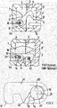
- Fig. 1 shows sections of concrete building boards 1 and 2, which are perpendicular to each other and form a room wall corner in a building erected by such concrete building boards (not shown).
- the abutting at 3 concrete slabs 1 and 2 each have a recess open on one side 4 and 5 respectively. Through the recesses 4 and 5 is formed when joining the plates, a closed space. 6
- a connecting element 7 is arranged, that is pivotally held on a cast in the concrete building board 1 coupling element 8 as indicated by arrow 9.
- a cast in the concrete building board 2 coupling counter-element 10 protrudes into the formed by the recess 5 portion of the space 6 inside.
- the Coupling element 8 comprises two U-shaped bent steel strand, the coupling counter-element 10 only such a steel strand.
- the connecting element 7 comprises a plate-shaped connecting body 11 with an undercut hook leg 12 at one end.
- a circular opening 13 for the storage of a circular rotating body 14 is formed.
- the rotary body 14 is eccentrically to its axis of rotation on each side of a journal 15, which engages in one of the two U-bend of the coupling element 8 respectively.
- the journal 15 has a frontal seat 16 for engagement of a hexagon turning tool, which is aligned to a (not shown) opening channel in the concrete slab 1.
- the connecting element 7 is pivoted by means of said hexagonal tool, the hook leg 12 engages between the U-legs of the coupling counter-element 10 and the connecting body 7 finally comes to rest on the coupling counter-element.
- a grain attached to the peripheral surface of the rotary body 14 and / or the inner surface of the opening 13 prevents the connector body 11 from moving relative to the rotary body 14 during this phase. From the time of the stop of the connecting body 11 against the coupling counter-element 10 is caused by further rotation of the rotary body 14 by means of the hexagonal turning tool caused by the grain locking of the rotary body 14 and the rotary body 14 in the in Fig. 1 b shown rotated position in which the hook leg 12 according to arrow 17 exerts a pulling force on the coupling counter-element 10.
- connection lock By a further (not shown) opening, which is arranged above the aligned to the seat 16 passage opening, the cavity 6 is then poured with in-situ concrete 18 and fixed the connecting element 7 in the position shown. Disadvantageously, before this fixation by the hardened in-situ concrete 18 by unintentional rotation of the rotary body 14 against the connecting body 11, the connection lock.
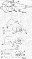
- the opening 13 in the connecting body 11 is not circular, but on its side facing away from the hook leg 12 has an extension 19.
- the width of the extension narrows below the diameter of the rotary body 14, wherein the wedge angle a of the constriction over a portion of the extension 19 is constant.
- the opening 13 is based on two circular openings whose centers are offset from each other in the direction mentioned and whose radii differ slightly.
- the inner wall of the opening 13 is bounded by the tangents to both circles, whereby the constriction area results with the constant wedge angle over a certain distance.
- the opening 13 has a first radius r 1 with a first radius center and in the region of the extension a second radius r 2 with a second radium center which is at a distance s from the first radius center. Between points where tangents 24 and 25 touch the circles corresponding to the radii r 1 and r 2 , the opening 13 is bounded by said tangents 24 and 25. In this section 26 delimited by the tangents, the wedge angle ⁇ of the constriction enclosed between the tangents 24, 25 is constant.
- the circular rotary body 14 has a seat 20 for the engagement of a hexagonal tool and an axis of rotation 23 of the rotary body 14 eccentrically arranged, extending in the axial direction through hole 21 for the coupling of a coupling element. Both the seat 20 and the through hole are formed directly in the rotary body, which is like the connecting body 11 plate-shaped.
- the reference numeral 22 indicates a shear-off pin, which ensures a co-movement of the connecting body 11 with the rotary body 14 up to a limit torque.
- the connecting element 7 is located on the coupling body 11 on the coupling counter-element 10, which thus prevents further rotation of the connecting element 7 in its entirety.
- the pin 22 can now be sheared off and the rotary body 14 can rotate in the opening 13 against the connecting body 11.
- the connecting body 11 shifts, inter alia, in the direction of the arrow 17 and the coupling counterpart 10 comes to bear against the undercut hook leg 12 of the connecting body 11.
- the rotary body shifts 14 now in the narrowing of the extension 19 of the opening 13 into and wedged in the constriction.
- the rotary body 14 is now rotatably locked in the opening 13 such that regardless of the rotational position of the rotary body 14, that is, regardless of whether the coupling element 8 on the rotary body 14 has a torque or not, there is no tendency to loosen the connection.
- connection device according to the prior art as far as possible avoided torque
- the device according to the invention avoids this disadvantage.
- a large rotational range of the rotary body 14 is available for the closed position.
- the device according to the invention allows a secure mounting of wall components, by in the phase in which in the cavity is not filled in situ fixing concrete, there is no risk to loosen the connection.
Description
Die Erfindung betrifft eine Vorrichtung zum Verbinden von Wand- oder/und Deckenbauteilen beim Errichten von Bauten, mit einem Verbindungselement, das einen Verbindungskörper mit Einrichtungen zur Ankopplung eines der Bauteile an den Verbindungskörper und einen gegen den Verbindungskörper drehbaren Drehkörper mit Einrichtungen zur Ankopplung des anderen Bauteils an den Drehkörper exzentrisch zu dessen Drehachse aufweist, wobei der Drehkörper in einer Öffnung in dem Verbindungskörper unter Erzeugung durch das Verbindungselement auf die angekoppelten Bauteile quer zur Drehachse des Drehkörpers ausgeübter Zugkräfte drehbar ist.The invention relates to a device for connecting wall and / or ceiling components in the construction of buildings, with a connecting element having a connecting body with means for coupling one of the components to the connecting body and a rotatable against the connecting body rotary body with means for coupling the other component to the rotary body eccentric to its axis of rotation, wherein the rotary body is rotatable in an opening in the connecting body to generate by the connecting element on the coupled components transverse to the rotational axis of the rotary body tensile forces exerted.
Eine solche Vorrichtung zur Verbindung von Wand- oder/und Deckenbauelementen ist in der
Der Erfindung liegt die Aufgabe zugrunde, eine neue, vor ungewollter Lockerung sichere Verbindungsvorrichtung zu schaffen.The invention has for its object to provide a new, safe from unwanted loosening connection device.
Die diese Aufgabe lösende Vorrichtung nach der Erfindung ist dadurch gekennzeichnet, dass die Öffnung eine sich entgegen der durch den Drehkörper auf das andere Bauteil ausgeübten Zugkraft erstreckende, sich in ihrer Breite unter den Durchmesser des Drehkörpers verengende Verlängerung aufweist.The device according to the invention which achieves this object is characterized in that the opening has an extension which extends counter to the tensile force exerted on the other component by the rotary body and which narrows in its width below the diameter of the rotary body.
Vorteilhaft sorgt die durch den Drehkörper auf eines der zu verbindenden Wand- und/oder Deckenbauteile ausgeübte Zugkraft dafür, dass der Drehkörper ab dem Moment, in welchem eine Kopplung zwischen dem Verbindungskörper und einem der Bauteile wirksam wird, beispielsweise wenn ein Hakenteil des Verbindungskörpers zu greifen beginnt, der Drehkörper in die Verengung eintritt und sich in der Verengung mit wachsenderZugspannung verkeilt. Bei ausreichender Zugspannung ist die Verkeilung derart fest, dass es unter keinen Umständen zu einer Lockerung des Drehkörpers kommen kann, auch dann nicht, wenn über die Ankopplung an den zu verbindenden Körper auf den Drehkörper durch die wirksame Zugkraft ein Drehmoment ausgeübt wird.Advantageously, the pulling force exerted by the rotary body on one of the wall and / or ceiling components to be connected ensures that the rotary body acts from the moment in which a coupling between the connecting body and one of the components takes effect, for example when a hook part of the connecting body engages begins, the rotary body enters the constriction and wedged in the constriction with increasing tensile stress. With sufficient tension, the wedging is so strong that it can not come under any circumstances to a loosening of the rotating body, not even if a torque is applied via the coupling to the body to be connected to the rotary body by the effective tensile force.
In vorteilhafter Ausgestaltung der Erfindung weist die Verengung einen in einem Abschnitt der Verlängerung konstanten Keilwinkel auf. Die Klemmkraft nimmt mit zunehmender Eintrittstiefe in die Verengung damit stetig zu.In an advantageous embodiment of the invention, the constriction has a constant wedge angle in a portion of the extension. The clamping force increases steadily with increasing depth of entry into the constriction.
Vorzugweise liegt die Länge des Abschnitts bei 3 % bis 15 % des Durchmessers des Drehkörpers.Preferably, the length of the section is 3% to 15% of the diameter of the rotating body.
Der Keilwinkel bewegt sich vorzugsweise zwischen 5° bis 15°. Insbesondere beträgt der konstante Keilwinkel 9°.The wedge angle preferably moves between 5 ° to 15 °. In particular, the constant wedge angle is 9 °.
In einer bevorzugten Ausführungsform weist die Öffnung unterschiedliche Radien mit zueinander mit Abstand angeordneten Radiusmittelpunkten auf. Der Abschnitt, in dem der Keilwinkel der Verengung konstant bleibt, liegt zwischen den jeweiligen Berührungspunkten der Tangenten an beide den Radien entsprechenden Kreise.In a preferred embodiment, the opening has different radii with radius centers arranged at a distance from each other. The section in which the wedge angle of the constriction remains constant lies between the respective points of contact of the tangents on both circles corresponding to the radii.
Zweckmäßig ist der Drehkörper ausschließlich durch eine kreisrunde Platte gebildet, wobei die Drehachse des Drehkörpers senkrecht auf den Plattenebenen steht und sich durch den Kreismittelpunkt erstreckt.Suitably, the rotary body is formed exclusively by a circular plate, wherein the axis of rotation of the rotary body is perpendicular to the plate planes and extends through the center of the circle.
In der Platte kann ein zu einer der Plattenebenen öffnender Sitz für die Aufnahme eines Drehwerkzeugs gebildet sein.In the plate, a seat opening to one of the plate planes may be formed for receiving a turning tool.
Die Einrichtungen zur Ankoppfung des anderen Teils umfassen zweckmäßig eine versetzt zur Drehachse angeordnete Öffnung, insbesondere eine Durchgangsöffnung, in die ein abgebogener oder U-förmiger Stahlstab, der z.B. in den Beton miteinander zu verbindender Wandbauteile eingebettet ist, eingreifen kann.The means for coupling the other part suitably comprise an opening arranged offset with respect to the axis of rotation, in particular a passage opening into which a bent or U-shaped steel rod, e.g. embedded in the concrete wall components to be joined together, can intervene.
In weiterer Ausgestaltung der Erfindung ist der Drehkörper in der Öffnung bis zu einem Grenzdrehmoment durch eine Arretierung relativ zum Verbindungskörper gegen Verdrehung gesichert.In a further embodiment of the invention, the rotary body is secured in the opening up to a limit torque by a lock relative to the connecting body against rotation.
Die Arretierung kann z.B: durch einen sich in eine Ausnehmung in dem Drehkörper und dem Verbindungskörper hinein erstreckenden Scherkörper, z.B. durch einen abscherbaren Stift, gebildet sein.The lock may be, for example, by a shear body extending into a recess in the rotating body and the connecting body, e.g. be formed by a shear-off pin.
Die Erfindung wird nachfolgend anhand eines Ausführungsbeispiels und der beiliegenden, sich auf dieses Ausführungsbeispiel beziehenden Zeichnungen weiter erläutert. Es zeigen:
- Fig. 1
- eine Verbindungsvorrichtung nach dem Stand der Technik,
- Fig. 2
- ein Verbindungselement einer erfindungsgemäßen Verbindungsvorrichtung,
- Fig. 3
- eine Darstellung zur Erläuterung der Gestaltung einer Öffnung in dem Verbindungselement von
Fig. 2 , und - Fig. 4
- eine die Funktion des Verbindungselements nach
Fig. 2 erläuternde Darstellung.
- Fig. 1
- a connecting device according to the prior art,
- Fig. 2
- a connecting element of a connecting device according to the invention,
- Fig. 3
- a representation for explaining the design of an opening in the connecting element of
Fig. 2 , and - Fig. 4
- one after the function of the connecting element
Fig. 2 explanatory illustration.
Die bei 3 aneinanderstoßenden Betonbauplatten 1 und 2 weisen jeweils eine einseitig offene Ausnehmung 4 bzw. 5 auf. Durch die Ausnehmungen 4 und 5 entsteht beim Zusammenfügen der Platten ein geschlossener Raum 6.The abutting at 3
In dem Raum 6 ist ein Verbindungselement 7 angeordnet, dass an einem in die Betonbauplatte 1 eingegossenen Kopplungselement 8 gemäß Pfeil 9 verschwenkbar gehalten ist. Ein in die Betonbauplatte 2 eingegossenes Kopplungsgegenelement 10 ragt in den durch die Ausnehmung 5 gebildeten Abschnitt des Raumes 6 hinein. Das Kopplungselement 8 umfasst zwei U-förmig gebogene Stahlströnge, das Kopplungsgegenelement 10 nur einen solchen Stahlstrang.In the
Das Verbindungselement 7 umfasst einen plattenförmigen Verbindungskörper 11 mit einem hinterschnittenen Hakenschenkel 12 an einem Ende. In einem dem Hakenschenkel 12 entgegengesetzten Endabschnitt des Verbindungskörpers 11 ist eine kreisrunde Öffnung 13 für die Lagerung eines kreisrunden Drehkörpers 14 gebildet. Von dem Drehkörper 14 steht exzentrisch zu seiner Drehachse auf jeder Seite ein Achszapfen 15 vor, welcher jeweils in einen der beiden U-Bogen des Kopplungselements 8 eingreift. Der Achszapfen 15 weist stirnseitig einen Sitz 16 für den Eingriff eines Sechskantdrehwerkzeugs auf, der zu einem (nicht gezeigten) Öffnungskanal in der Betonbauplatte 1 ausgerichtet ist.The connecting
Um die Betonbauplatten 1,2 miteinander zu verbinden, wird das Verbindungselement 7 mit Hilfe des genannten Sechskantwerkzeugs verschwenkt, wobei der Hakenschenkel 12 zwischen den U-Schenkeln des Kopplungsgegenelements 10 eingreift und der Verbindungskörper 7 schließlich zur Auflage auf dem Kopplungsgegenelement gelangt. Eine auf der Umfangsfläche des Drehkörpers 14 oder/und der Innenfläche der Öffnung 13 angebrachte Körnung verhindert, dass sich während dieser Phase der Verbindungskörper 11 relativ zu dem Drehkörper 14 bewegt. Vom Zeitpunkt des Anschlags des Verbindungskörpers 11 gegen das Kopplungsgegenelement 10 an wird durch weitere Drehung des Drehkörpers 14 mit Hilfe des Sechskantdrehwerkzeugs die durch die Körnung bewirkte Arretierung des Drehkörpers 14 überwunden und der Drehkörper 14 in die in
Durch eine weitere (nicht gezeigte) Öffnung, die oberhalb der zu dem Sitz 16 ausgerichteten Durchgangsöffnung angeordnet ist, wird der Hohlraum 6 anschließend mit Ortbeton 18 ausgegossen und das Verbindungselement 7 in der gezeigten Position fixiert. Nachteilig kann sich vor dieser Fixierung durch den abgebundenen Ortbeton 18 durch ungewollte Drehung des Drehkörpers 14 gegen den Verbindungskörper 11 die Verbindung lockem.By a further (not shown) opening, which is arranged above the aligned to the
Dieser Nachteil lässt sich durch ein in
In dem gezeigten Ausführungsbeispiel liegen der Öffnung 13 zwei kreisrunde Öffnungen zugrunde, deren Zentren in der genannten Richtung zueinander versetzt sind, und deren Radien sich geringfügig unterscheiden. In der Übergangszone ist die Innenwand der Öffnung 13 durch die Tangenten an beide Kreise begrenzt, wodurch sich der Verengungsbereich mit dem über eine gewisse Strecke konstanten Keilwinkel ergibt.In the exemplary embodiment shown, the
Zur Verdeutlichung ist in
Wie
Zur Herstellung einer Verbindung zwischen einem Kopplungselement 8, das hakenartig in die Durchgangsöffnung 21 eingreift, und einem U-förmigen Kopplungsgegenelement 10 wird das Verbindungselement 7 aus der in
In der in
Der Drehkörper 14 ist nun in der Öffnung 13 derart drehfest arretiert, dass unabhängig von der Drehposition des Drehkörpers 14, d.h. unabhängig davon, ob das Kopplungselement 8 auf den Drehkörper 14 ein Drehmoment ausübt oder nicht, keinerlei Tendenz zur Lockerung der Verbindung besteht. Im Unterschied dazu müsste in der in
Vorteilhaft meidet die Vorrichtung nach der Erfindung diesen Nachteil. Zur Herstellung einer solchen Zugverbindung steht für die Schließposition ein großer Drehbereich des Drehkörpers 14 zur Verfügung.
Die Vorrichtung nach der Erfindung erlaubt eine sichere Montage von Wandbauteilen, indem in der Phase, in welcher in den Hohlraum noch kein fixierender Ortbeton eingefüllt ist, keine Gefahr zur Lockerung der Verbindung besteht.Advantageously, the device according to the invention avoids this disadvantage. To produce such a tension connection, a large rotational range of the
The device according to the invention allows a secure mounting of wall components, by in the phase in which in the cavity is not filled in situ fixing concrete, there is no risk to loosen the connection.
Claims (10)
- Device for connecting wall and/or ceiling components when erecting structures, having a connecting element (7) which has a connecting body (11) with means for coupling one of the components (8, 10) to the connecting body (11) and a rotating body (14) that can be rotated with respect to the connecting body (11) and has means for coupling the other component (8) to the rotating body (14), eccentrically with respect to the axis of rotation of the latter, where the rotating body (14) can be rotated in an opening (13) in the connecting body (11), generating tensile forces exerted by the connecting element (7) on the coupled components (8, 10), transversely with respect to the axis of rotation of the rotating body (14),
characterized in that
the opening (13) has an extension (19) extending counter to the tensile force exerted by the rotating body (14) on the other component (8) and narrowing in its width below the diameter of the rotating body (14). - Device according to Claim 1,
characterized in that
the narrowing has a section with a constant wedge angle α of the narrowing. - Device according to Claim 2,
characterized in that
the length of the section is around 3% to 15% of the diameter of the rotating body (14). - Device according to one of Claims 1 to 3,
characterized in that
the wedge angle of the narrowing is around 5° to 15°, and in particular the constant wedge angle is around 9°. - Device according to one of Claims 1 to 4,
characterized in that
the opening (13) has different radii (r1, r2) with radius centres arranged relative to one another at a distance (s) from one another. - Device according to one of Claims 1 to 5,
characterized in that
the rotating body (14) is formed exclusively by a circular plate, and the axis of rotation of the rotating body (14) extends at right angles to the plate plane, through the centre of the circle. - Device according to Claim 6,
characterized in that
a seat (20) is formed in the plate, opening toward one of the plate planes, to accommodate a rotary tool. - Device according to one of Claims 1 to 7,
characterized in that
the means for coupling the other part (8) comprise an opening, in particular a passage opening (21), in the rotating body (14), arranged to be offset with respect to the axis of rotation (23) of the rotating body (14). - Device according to one of Claims 1 to 8,
characterized in that
the rotating body (14) is secured against rotation by a locking means (22) that can be loaded up to a limiting torque. - Device according to Claim 9,
characterized in that
the locking means is formed by a shearable body (22) engaging in the rotating body (14) and in the connecting body (11).
Applications Claiming Priority (1)
| Application Number | Priority Date | Filing Date | Title |
|---|---|---|---|
| DE102012101639A DE102012101639A1 (en) | 2012-02-29 | 2012-02-29 | connecting device |
Publications (3)
| Publication Number | Publication Date |
|---|---|
| EP2634323A2 EP2634323A2 (en) | 2013-09-04 |
| EP2634323A3 EP2634323A3 (en) | 2014-03-26 |
| EP2634323B1 true EP2634323B1 (en) | 2017-01-18 |
Family
ID=47900558
Family Applications (1)
| Application Number | Title | Priority Date | Filing Date |
|---|---|---|---|
| EP13156668.9A Active EP2634323B1 (en) | 2012-02-29 | 2013-02-26 | Connecting device |
Country Status (3)
| Country | Link |
|---|---|
| EP (1) | EP2634323B1 (en) |
| DE (1) | DE102012101639A1 (en) |
| DK (1) | DK2634323T3 (en) |
Families Citing this family (1)
| Publication number | Priority date | Publication date | Assignee | Title |
|---|---|---|---|---|
| DE102014117832A1 (en) | 2014-12-04 | 2016-06-09 | Christian Weidemann | Device for connecting wall or / and ceiling components when erecting buildings |
Citations (1)
| Publication number | Priority date | Publication date | Assignee | Title |
|---|---|---|---|---|
| CH98264A (en) * | 1921-07-21 | 1923-03-01 | Rohmer Gabriel Emile | Sealing pad. |
Family Cites Families (1)
| Publication number | Priority date | Publication date | Assignee | Title |
|---|---|---|---|---|
| DE102007015830A1 (en) | 2007-03-30 | 2008-10-02 | Weidemann, Christian | Device for connecting wall and/or ceiling components during erection of buildings comprises recesses for the components to be aligned with each other with openings forming a hollow chamber, a connecting element and fixing units |
-
2012
- 2012-02-29 DE DE102012101639A patent/DE102012101639A1/en not_active Withdrawn
-
2013
- 2013-02-26 EP EP13156668.9A patent/EP2634323B1/en active Active
- 2013-02-26 DK DK13156668.9T patent/DK2634323T3/en active
Patent Citations (1)
| Publication number | Priority date | Publication date | Assignee | Title |
|---|---|---|---|---|
| CH98264A (en) * | 1921-07-21 | 1923-03-01 | Rohmer Gabriel Emile | Sealing pad. |
Also Published As
| Publication number | Publication date |
|---|---|
| DK2634323T3 (en) | 2017-05-01 |
| DE102012101639A1 (en) | 2013-08-29 |
| EP2634323A3 (en) | 2014-03-26 |
| EP2634323A2 (en) | 2013-09-04 |
Similar Documents
| Publication | Publication Date | Title |
|---|---|---|
| EP2678571B1 (en) | Corner connector for hollow profiles | |
| WO2005040526A1 (en) | Formwork system | |
| DE1650975A1 (en) | Device for connecting or connecting components | |
| WO2013079681A1 (en) | Profile bar, profile assembly and method for producing a profile assembly | |
| EP2636830B1 (en) | Door hinge fastening, assembly comprising the door hinge fastening and a door hinge and door assembly | |
| AT519093B1 (en) | Connecting device for connecting thin-walled finished parts and finished parts equipped therewith | |
| EP3214234A1 (en) | Prefabricated parts connector and connection system for connecting prefabricated concrete parts | |
| DE102014106068B4 (en) | Device for connecting two opposing plate-shaped formwork elements | |
| EP3529430B1 (en) | Post for a post-and-beam construction | |
| EP2634323B1 (en) | Connecting device | |
| DE102007015830A1 (en) | Device for connecting wall and/or ceiling components during erection of buildings comprises recesses for the components to be aligned with each other with openings forming a hollow chamber, a connecting element and fixing units | |
| EP3214235B1 (en) | Connection system for connecting prefabricated concrete parts | |
| EP1702120B1 (en) | Formwork system | |
| EP2982807B1 (en) | Device for connecting two components separated by a joint | |
| DE202011003315U1 (en) | connecting device | |
| EP2458229B1 (en) | Connecting device | |
| DE202018105138U1 (en) | cable connection | |
| EP2873778A1 (en) | Connection arrangement and connection system for prefabricated concrete elements | |
| DE102019106067A1 (en) | Fastening device for a frame element and fastening arrangement | |
| DE102018107081A1 (en) | Anchoring device for a formwork anchor and formwork anchor | |
| EP3663592B1 (en) | Connector system | |
| AT403398B (en) | TENSILE CONNECTION FOR PRE-FITTED HOUSE CHIMNEYS | |
| WO2016086921A1 (en) | Device for connecting wall and/or ceiling components during the erection of buildings | |
| DE2734520C3 (en) | Formwork tie rods made of plastic | |
| DE19835788A1 (en) | Mounting device |
Legal Events
| Date | Code | Title | Description |
|---|---|---|---|
| PUAI | Public reference made under article 153(3) epc to a published international application that has entered the european phase |
Free format text: ORIGINAL CODE: 0009012 |
|
| AK | Designated contracting states |
Kind code of ref document: A2 Designated state(s): AL AT BE BG CH CY CZ DE DK EE ES FI FR GB GR HR HU IE IS IT LI LT LU LV MC MK MT NL NO PL PT RO RS SE SI SK SM TR |
|
| AX | Request for extension of the european patent |
Extension state: BA ME |
|
| PUAL | Search report despatched |
Free format text: ORIGINAL CODE: 0009013 |
|
| AK | Designated contracting states |
Kind code of ref document: A3 Designated state(s): AL AT BE BG CH CY CZ DE DK EE ES FI FR GB GR HR HU IE IS IT LI LT LU LV MC MK MT NL NO PL PT RO RS SE SI SK SM TR |
|
| AX | Request for extension of the european patent |
Extension state: BA ME |
|
| RIC1 | Information provided on ipc code assigned before grant |
Ipc: E04B 1/04 20060101ALN20140218BHEP Ipc: E04B 1/61 20060101AFI20140218BHEP |
|
| 17P | Request for examination filed |
Effective date: 20140923 |
|
| RAX | Requested extension states of the european patent have changed |
Extension state: ME Payment date: 20140923 Extension state: BA Payment date: 20140923 |
|
| RBV | Designated contracting states (corrected) |
Designated state(s): AL AT BE BG CH CY CZ DE DK EE ES FI FR GB GR HR HU IE IS IT LI LT LU LV MC MK MT NL NO PL PT RO RS SE SI SK SM TR |
|
| 17Q | First examination report despatched |
Effective date: 20150518 |
|
| GRAP | Despatch of communication of intention to grant a patent |
Free format text: ORIGINAL CODE: EPIDOSNIGR1 |
|
| RIC1 | Information provided on ipc code assigned before grant |
Ipc: E05B 65/08 20060101ALN20160509BHEP Ipc: E04B 1/04 20060101ALN20160509BHEP Ipc: E04B 1/61 20060101AFI20160509BHEP |
|
| INTG | Intention to grant announced |
Effective date: 20160602 |
|
| RIC1 | Information provided on ipc code assigned before grant |
Ipc: E04B 1/61 20060101AFI20160524BHEP Ipc: E04B 1/04 20060101ALN20160524BHEP Ipc: E05B 65/08 20060101ALN20160524BHEP |
|
| GRAJ | Information related to disapproval of communication of intention to grant by the applicant or resumption of examination proceedings by the epo deleted |
Free format text: ORIGINAL CODE: EPIDOSDIGR1 |
|
| GRAP | Despatch of communication of intention to grant a patent |
Free format text: ORIGINAL CODE: EPIDOSNIGR1 |
|
| INTG | Intention to grant announced |
Effective date: 20160805 |
|
| RIC1 | Information provided on ipc code assigned before grant |
Ipc: E04B 1/61 20060101AFI20160728BHEP Ipc: E04B 1/04 20060101ALN20160728BHEP Ipc: E05B 65/08 20060101ALN20160728BHEP |
|
| GRAS | Grant fee paid |
Free format text: ORIGINAL CODE: EPIDOSNIGR3 |
|
| GRAA | (expected) grant |
Free format text: ORIGINAL CODE: 0009210 |
|
| AK | Designated contracting states |
Kind code of ref document: B1 Designated state(s): AL AT BE BG CH CY CZ DE DK EE ES FI FR GB GR HR HU IE IS IT LI LT LU LV MC MK MT NL NO PL PT RO RS SE SI SK SM TR |
|
| AX | Request for extension of the european patent |
Extension state: BA ME |
|
| REG | Reference to a national code |
Ref country code: GB Ref legal event code: FG4D Free format text: NOT ENGLISH |
|
| REG | Reference to a national code |
Ref country code: CH Ref legal event code: EP |
|
| REG | Reference to a national code |
Ref country code: AT Ref legal event code: REF Ref document number: 863010 Country of ref document: AT Kind code of ref document: T Effective date: 20170215 |
|
| REG | Reference to a national code |
Ref country code: IE Ref legal event code: FG4D Free format text: LANGUAGE OF EP DOCUMENT: GERMAN |
|
| REG | Reference to a national code |
Ref country code: DE Ref legal event code: R096 Ref document number: 502013006127 Country of ref document: DE |
|
| REG | Reference to a national code |
Ref country code: NL Ref legal event code: FP |
|
| REG | Reference to a national code |
Ref country code: SE Ref legal event code: TRGR |
|
| REG | Reference to a national code |
Ref country code: DK Ref legal event code: T3 Effective date: 20170427 |
|
| REG | Reference to a national code |
Ref country code: LT Ref legal event code: MG4D |
|
| PG25 | Lapsed in a contracting state [announced via postgrant information from national office to epo] |
Ref country code: BE Free format text: LAPSE BECAUSE OF NON-PAYMENT OF DUE FEES Effective date: 20170228 |
|
| REG | Reference to a national code |
Ref country code: NO Ref legal event code: T2 Effective date: 20170118 |
|
| PG25 | Lapsed in a contracting state [announced via postgrant information from national office to epo] |
Ref country code: LT Free format text: LAPSE BECAUSE OF FAILURE TO SUBMIT A TRANSLATION OF THE DESCRIPTION OR TO PAY THE FEE WITHIN THE PRESCRIBED TIME-LIMIT Effective date: 20170118 Ref country code: HR Free format text: LAPSE BECAUSE OF FAILURE TO SUBMIT A TRANSLATION OF THE DESCRIPTION OR TO PAY THE FEE WITHIN THE PRESCRIBED TIME-LIMIT Effective date: 20170118 Ref country code: IS Free format text: LAPSE BECAUSE OF FAILURE TO SUBMIT A TRANSLATION OF THE DESCRIPTION OR TO PAY THE FEE WITHIN THE PRESCRIBED TIME-LIMIT Effective date: 20170518 Ref country code: GR Free format text: LAPSE BECAUSE OF FAILURE TO SUBMIT A TRANSLATION OF THE DESCRIPTION OR TO PAY THE FEE WITHIN THE PRESCRIBED TIME-LIMIT Effective date: 20170419 |
|
| PG25 | Lapsed in a contracting state [announced via postgrant information from national office to epo] |
Ref country code: RS Free format text: LAPSE BECAUSE OF FAILURE TO SUBMIT A TRANSLATION OF THE DESCRIPTION OR TO PAY THE FEE WITHIN THE PRESCRIBED TIME-LIMIT Effective date: 20170118 Ref country code: LV Free format text: LAPSE BECAUSE OF FAILURE TO SUBMIT A TRANSLATION OF THE DESCRIPTION OR TO PAY THE FEE WITHIN THE PRESCRIBED TIME-LIMIT Effective date: 20170118 Ref country code: PT Free format text: LAPSE BECAUSE OF FAILURE TO SUBMIT A TRANSLATION OF THE DESCRIPTION OR TO PAY THE FEE WITHIN THE PRESCRIBED TIME-LIMIT Effective date: 20170518 Ref country code: BG Free format text: LAPSE BECAUSE OF FAILURE TO SUBMIT A TRANSLATION OF THE DESCRIPTION OR TO PAY THE FEE WITHIN THE PRESCRIBED TIME-LIMIT Effective date: 20170418 Ref country code: PL Free format text: LAPSE BECAUSE OF FAILURE TO SUBMIT A TRANSLATION OF THE DESCRIPTION OR TO PAY THE FEE WITHIN THE PRESCRIBED TIME-LIMIT Effective date: 20170118 Ref country code: ES Free format text: LAPSE BECAUSE OF FAILURE TO SUBMIT A TRANSLATION OF THE DESCRIPTION OR TO PAY THE FEE WITHIN THE PRESCRIBED TIME-LIMIT Effective date: 20170118 |
|
| REG | Reference to a national code |
Ref country code: CH Ref legal event code: PL |
|
| REG | Reference to a national code |
Ref country code: DE Ref legal event code: R097 Ref document number: 502013006127 Country of ref document: DE |
|
| PG25 | Lapsed in a contracting state [announced via postgrant information from national office to epo] |
Ref country code: RO Free format text: LAPSE BECAUSE OF FAILURE TO SUBMIT A TRANSLATION OF THE DESCRIPTION OR TO PAY THE FEE WITHIN THE PRESCRIBED TIME-LIMIT Effective date: 20170118 Ref country code: SK Free format text: LAPSE BECAUSE OF FAILURE TO SUBMIT A TRANSLATION OF THE DESCRIPTION OR TO PAY THE FEE WITHIN THE PRESCRIBED TIME-LIMIT Effective date: 20170118 Ref country code: CH Free format text: LAPSE BECAUSE OF NON-PAYMENT OF DUE FEES Effective date: 20170228 Ref country code: LI Free format text: LAPSE BECAUSE OF NON-PAYMENT OF DUE FEES Effective date: 20170228 Ref country code: CZ Free format text: LAPSE BECAUSE OF FAILURE TO SUBMIT A TRANSLATION OF THE DESCRIPTION OR TO PAY THE FEE WITHIN THE PRESCRIBED TIME-LIMIT Effective date: 20170118 Ref country code: EE Free format text: LAPSE BECAUSE OF FAILURE TO SUBMIT A TRANSLATION OF THE DESCRIPTION OR TO PAY THE FEE WITHIN THE PRESCRIBED TIME-LIMIT Effective date: 20170118 |
|
| PLBE | No opposition filed within time limit |
Free format text: ORIGINAL CODE: 0009261 |
|
| STAA | Information on the status of an ep patent application or granted ep patent |
Free format text: STATUS: NO OPPOSITION FILED WITHIN TIME LIMIT |
|
| REG | Reference to a national code |
Ref country code: IE Ref legal event code: MM4A |
|
| PG25 | Lapsed in a contracting state [announced via postgrant information from national office to epo] |
Ref country code: SM Free format text: LAPSE BECAUSE OF FAILURE TO SUBMIT A TRANSLATION OF THE DESCRIPTION OR TO PAY THE FEE WITHIN THE PRESCRIBED TIME-LIMIT Effective date: 20170118 Ref country code: MC Free format text: LAPSE BECAUSE OF FAILURE TO SUBMIT A TRANSLATION OF THE DESCRIPTION OR TO PAY THE FEE WITHIN THE PRESCRIBED TIME-LIMIT Effective date: 20170118 |
|
| REG | Reference to a national code |
Ref country code: FR Ref legal event code: ST Effective date: 20171031 |
|
| 26N | No opposition filed |
Effective date: 20171019 |
|
| PG25 | Lapsed in a contracting state [announced via postgrant information from national office to epo] |
Ref country code: LU Free format text: LAPSE BECAUSE OF NON-PAYMENT OF DUE FEES Effective date: 20170226 |
|
| PG25 | Lapsed in a contracting state [announced via postgrant information from national office to epo] |
Ref country code: FR Free format text: LAPSE BECAUSE OF NON-PAYMENT OF DUE FEES Effective date: 20170320 |
|
| REG | Reference to a national code |
Ref country code: BE Ref legal event code: MM Effective date: 20170228 |
|
| PG25 | Lapsed in a contracting state [announced via postgrant information from national office to epo] |
Ref country code: IE Free format text: LAPSE BECAUSE OF NON-PAYMENT OF DUE FEES Effective date: 20170226 Ref country code: SI Free format text: LAPSE BECAUSE OF FAILURE TO SUBMIT A TRANSLATION OF THE DESCRIPTION OR TO PAY THE FEE WITHIN THE PRESCRIBED TIME-LIMIT Effective date: 20170118 |
|
| PGFP | Annual fee paid to national office [announced via postgrant information from national office to epo] |
Ref country code: NL Payment date: 20180221 Year of fee payment: 6 |
|
| PGFP | Annual fee paid to national office [announced via postgrant information from national office to epo] |
Ref country code: DE Payment date: 20180125 Year of fee payment: 6 Ref country code: FI Payment date: 20180216 Year of fee payment: 6 Ref country code: GB Payment date: 20180221 Year of fee payment: 6 Ref country code: NO Payment date: 20180221 Year of fee payment: 6 Ref country code: DK Payment date: 20180221 Year of fee payment: 6 |
|
| PGFP | Annual fee paid to national office [announced via postgrant information from national office to epo] |
Ref country code: IT Payment date: 20180221 Year of fee payment: 6 Ref country code: AT Payment date: 20180220 Year of fee payment: 6 Ref country code: SE Payment date: 20180222 Year of fee payment: 6 |
|
| PG25 | Lapsed in a contracting state [announced via postgrant information from national office to epo] |
Ref country code: MT Free format text: LAPSE BECAUSE OF FAILURE TO SUBMIT A TRANSLATION OF THE DESCRIPTION OR TO PAY THE FEE WITHIN THE PRESCRIBED TIME-LIMIT Effective date: 20170118 |
|
| PG25 | Lapsed in a contracting state [announced via postgrant information from national office to epo] |
Ref country code: HU Free format text: LAPSE BECAUSE OF FAILURE TO SUBMIT A TRANSLATION OF THE DESCRIPTION OR TO PAY THE FEE WITHIN THE PRESCRIBED TIME-LIMIT; INVALID AB INITIO Effective date: 20130226 |
|
| REG | Reference to a national code |
Ref country code: DE Ref legal event code: R119 Ref document number: 502013006127 Country of ref document: DE |
|
| REG | Reference to a national code |
Ref country code: DK Ref legal event code: EBP Effective date: 20190228 Ref country code: NO Ref legal event code: MMEP |
|
| REG | Reference to a national code |
Ref country code: SE Ref legal event code: EUG |
|
| REG | Reference to a national code |
Ref country code: NL Ref legal event code: MM Effective date: 20190301 |
|
| REG | Reference to a national code |
Ref country code: AT Ref legal event code: MM01 Ref document number: 863010 Country of ref document: AT Kind code of ref document: T Effective date: 20190226 |
|
| GBPC | Gb: european patent ceased through non-payment of renewal fee |
Effective date: 20190226 |
|
| PG25 | Lapsed in a contracting state [announced via postgrant information from national office to epo] |
Ref country code: CY Free format text: LAPSE BECAUSE OF NON-PAYMENT OF DUE FEES Effective date: 20170118 Ref country code: NO Free format text: LAPSE BECAUSE OF NON-PAYMENT OF DUE FEES Effective date: 20190228 Ref country code: SE Free format text: LAPSE BECAUSE OF NON-PAYMENT OF DUE FEES Effective date: 20190227 Ref country code: FI Free format text: LAPSE BECAUSE OF NON-PAYMENT OF DUE FEES Effective date: 20190226 |
|
| PG25 | Lapsed in a contracting state [announced via postgrant information from national office to epo] |
Ref country code: MK Free format text: LAPSE BECAUSE OF FAILURE TO SUBMIT A TRANSLATION OF THE DESCRIPTION OR TO PAY THE FEE WITHIN THE PRESCRIBED TIME-LIMIT Effective date: 20170118 |
|
| PG25 | Lapsed in a contracting state [announced via postgrant information from national office to epo] |
Ref country code: AT Free format text: LAPSE BECAUSE OF NON-PAYMENT OF DUE FEES Effective date: 20190226 |
|
| PG25 | Lapsed in a contracting state [announced via postgrant information from national office to epo] |
Ref country code: DK Free format text: LAPSE BECAUSE OF NON-PAYMENT OF DUE FEES Effective date: 20190228 Ref country code: DE Free format text: LAPSE BECAUSE OF NON-PAYMENT OF DUE FEES Effective date: 20190903 Ref country code: GB Free format text: LAPSE BECAUSE OF NON-PAYMENT OF DUE FEES Effective date: 20190226 Ref country code: NL Free format text: LAPSE BECAUSE OF NON-PAYMENT OF DUE FEES Effective date: 20190301 |
|
| PG25 | Lapsed in a contracting state [announced via postgrant information from national office to epo] |
Ref country code: IT Free format text: LAPSE BECAUSE OF NON-PAYMENT OF DUE FEES Effective date: 20190226 |
|
| PG25 | Lapsed in a contracting state [announced via postgrant information from national office to epo] |
Ref country code: TR Free format text: LAPSE BECAUSE OF FAILURE TO SUBMIT A TRANSLATION OF THE DESCRIPTION OR TO PAY THE FEE WITHIN THE PRESCRIBED TIME-LIMIT Effective date: 20170118 |
|
| PG25 | Lapsed in a contracting state [announced via postgrant information from national office to epo] |
Ref country code: AL Free format text: LAPSE BECAUSE OF FAILURE TO SUBMIT A TRANSLATION OF THE DESCRIPTION OR TO PAY THE FEE WITHIN THE PRESCRIBED TIME-LIMIT Effective date: 20170118 |