EP2633799B1 - Plattform zur Visualisierung des Portzugangs - Google Patents
Plattform zur Visualisierung des Portzugangs Download PDFInfo
- Publication number
- EP2633799B1 EP2633799B1 EP13155705.0A EP13155705A EP2633799B1 EP 2633799 B1 EP2633799 B1 EP 2633799B1 EP 13155705 A EP13155705 A EP 13155705A EP 2633799 B1 EP2633799 B1 EP 2633799B1
- Authority
- EP
- European Patent Office
- Prior art keywords
- sheath
- medical system
- distal
- relative
- guide sheath
- Prior art date
- Legal status (The legal status is an assumption and is not a legal conclusion. Google has not performed a legal analysis and makes no representation as to the accuracy of the status listed.)
- Active
Links
Images


Classifications
-
- A—HUMAN NECESSITIES
- A61—MEDICAL OR VETERINARY SCIENCE; HYGIENE
- A61B—DIAGNOSIS; SURGERY; IDENTIFICATION
- A61B1/00—Instruments for performing medical examinations of the interior of cavities or tubes of the body by visual or photographical inspection, e.g. endoscopes; Illuminating arrangements therefor
- A61B1/313—Instruments for performing medical examinations of the interior of cavities or tubes of the body by visual or photographical inspection, e.g. endoscopes; Illuminating arrangements therefor for introducing through surgical openings, e.g. laparoscopes
- A61B1/3132—Instruments for performing medical examinations of the interior of cavities or tubes of the body by visual or photographical inspection, e.g. endoscopes; Illuminating arrangements therefor for introducing through surgical openings, e.g. laparoscopes for laparoscopy
-
- A—HUMAN NECESSITIES
- A61—MEDICAL OR VETERINARY SCIENCE; HYGIENE
- A61B—DIAGNOSIS; SURGERY; IDENTIFICATION
- A61B1/00—Instruments for performing medical examinations of the interior of cavities or tubes of the body by visual or photographical inspection, e.g. endoscopes; Illuminating arrangements therefor
- A61B1/00147—Holding or positioning arrangements
- A61B1/00154—Holding or positioning arrangements using guiding arrangements for insertion
-
- A—HUMAN NECESSITIES
- A61—MEDICAL OR VETERINARY SCIENCE; HYGIENE
- A61B—DIAGNOSIS; SURGERY; IDENTIFICATION
- A61B1/00—Instruments for performing medical examinations of the interior of cavities or tubes of the body by visual or photographical inspection, e.g. endoscopes; Illuminating arrangements therefor
- A61B1/005—Flexible endoscopes
- A61B1/0051—Flexible endoscopes with controlled bending of insertion part
- A61B1/0055—Constructional details of insertion parts, e.g. vertebral elements
-
- A—HUMAN NECESSITIES
- A61—MEDICAL OR VETERINARY SCIENCE; HYGIENE
- A61B—DIAGNOSIS; SURGERY; IDENTIFICATION
- A61B1/00—Instruments for performing medical examinations of the interior of cavities or tubes of the body by visual or photographical inspection, e.g. endoscopes; Illuminating arrangements therefor
- A61B1/005—Flexible endoscopes
- A61B1/0051—Flexible endoscopes with controlled bending of insertion part
- A61B1/0055—Constructional details of insertion parts, e.g. vertebral elements
- A61B1/0056—Constructional details of insertion parts, e.g. vertebral elements the insertion parts being asymmetric, e.g. for unilateral bending mechanisms
-
- A—HUMAN NECESSITIES
- A61—MEDICAL OR VETERINARY SCIENCE; HYGIENE
- A61B—DIAGNOSIS; SURGERY; IDENTIFICATION
- A61B1/00—Instruments for performing medical examinations of the interior of cavities or tubes of the body by visual or photographical inspection, e.g. endoscopes; Illuminating arrangements therefor
- A61B1/005—Flexible endoscopes
- A61B1/008—Articulations
-
- A—HUMAN NECESSITIES
- A61—MEDICAL OR VETERINARY SCIENCE; HYGIENE
- A61B—DIAGNOSIS; SURGERY; IDENTIFICATION
- A61B1/00—Instruments for performing medical examinations of the interior of cavities or tubes of the body by visual or photographical inspection, e.g. endoscopes; Illuminating arrangements therefor
- A61B1/04—Instruments for performing medical examinations of the interior of cavities or tubes of the body by visual or photographical inspection, e.g. endoscopes; Illuminating arrangements therefor combined with photographic or television appliances
- A61B1/044—Instruments for performing medical examinations of the interior of cavities or tubes of the body by visual or photographical inspection, e.g. endoscopes; Illuminating arrangements therefor combined with photographic or television appliances for absorption imaging
-
- A—HUMAN NECESSITIES
- A61—MEDICAL OR VETERINARY SCIENCE; HYGIENE
- A61B—DIAGNOSIS; SURGERY; IDENTIFICATION
- A61B17/00—Surgical instruments, devices or methods
- A61B17/02—Surgical instruments, devices or methods for holding wounds open, e.g. retractors; Tractors
- A61B17/0293—Surgical instruments, devices or methods for holding wounds open, e.g. retractors; Tractors with ring member to support retractor elements
-
- A—HUMAN NECESSITIES
- A61—MEDICAL OR VETERINARY SCIENCE; HYGIENE
- A61B—DIAGNOSIS; SURGERY; IDENTIFICATION
- A61B17/00—Surgical instruments, devices or methods
- A61B17/34—Trocars; Puncturing needles
- A61B17/3417—Details of tips or shafts, e.g. grooves, expandable, bendable; Multiple coaxial sliding cannulas, e.g. for dilating
- A61B17/3421—Cannulas
- A61B17/3423—Access ports, e.g. toroid shape introducers for instruments or hands
-
- A—HUMAN NECESSITIES
- A61—MEDICAL OR VETERINARY SCIENCE; HYGIENE
- A61B—DIAGNOSIS; SURGERY; IDENTIFICATION
- A61B1/00—Instruments for performing medical examinations of the interior of cavities or tubes of the body by visual or photographical inspection, e.g. endoscopes; Illuminating arrangements therefor
- A61B1/04—Instruments for performing medical examinations of the interior of cavities or tubes of the body by visual or photographical inspection, e.g. endoscopes; Illuminating arrangements therefor combined with photographic or television appliances
- A61B1/05—Instruments for performing medical examinations of the interior of cavities or tubes of the body by visual or photographical inspection, e.g. endoscopes; Illuminating arrangements therefor combined with photographic or television appliances characterised by the image sensor, e.g. camera, being in the distal end portion
-
- A—HUMAN NECESSITIES
- A61—MEDICAL OR VETERINARY SCIENCE; HYGIENE
- A61B—DIAGNOSIS; SURGERY; IDENTIFICATION
- A61B17/00—Surgical instruments, devices or methods
- A61B17/00234—Surgical instruments, devices or methods for minimally invasive surgery
- A61B2017/00238—Type of minimally invasive operation
- A61B2017/00283—Type of minimally invasive operation with a device releasably connected to an inner wall of the abdomen during surgery, e.g. an illumination source
-
- A—HUMAN NECESSITIES
- A61—MEDICAL OR VETERINARY SCIENCE; HYGIENE
- A61B—DIAGNOSIS; SURGERY; IDENTIFICATION
- A61B17/00—Surgical instruments, devices or methods
- A61B17/00234—Surgical instruments, devices or methods for minimally invasive surgery
- A61B2017/00292—Surgical instruments, devices or methods for minimally invasive surgery mounted on or guided by flexible, e.g. catheter-like, means
- A61B2017/003—Steerable
- A61B2017/00305—Constructional details of the flexible means
-
- A—HUMAN NECESSITIES
- A61—MEDICAL OR VETERINARY SCIENCE; HYGIENE
- A61B—DIAGNOSIS; SURGERY; IDENTIFICATION
- A61B17/00—Surgical instruments, devices or methods
- A61B17/34—Trocars; Puncturing needles
- A61B17/3417—Details of tips or shafts, e.g. grooves, expandable, bendable; Multiple coaxial sliding cannulas, e.g. for dilating
- A61B17/3421—Cannulas
- A61B2017/3445—Cannulas used as instrument channel for multiple instruments
-
- A—HUMAN NECESSITIES
- A61—MEDICAL OR VETERINARY SCIENCE; HYGIENE
- A61B—DIAGNOSIS; SURGERY; IDENTIFICATION
- A61B90/00—Instruments, implements or accessories specially adapted for surgery or diagnosis and not covered by any of the groups A61B1/00 - A61B50/00, e.g. for luxation treatment or for protecting wound edges
- A61B90/36—Image-producing devices or illumination devices not otherwise provided for
- A61B90/361—Image-producing devices, e.g. surgical cameras
Definitions
- the present invention relates generally to medical devices and systems for use with laparoscopic procedures, and more particularly to apparatus for guiding medical instruments during such procedures.
- a trocar port is device having a tubular configuration defining a port opening and having a configuration that engages the tissue to hold the site open.
- Multiple puncture sites are provided in the desired area so that multiple instruments may be used for the particular laparoscopic procedure, as well as to allow for triangulation of the target structure.
- a laparoscope or other visualization system may utilize one port, while a grasper or other tissue manipulator is used with the second port in conjunction with a cutting or suturing device utilized through the third port. While laparoscopic procedures are less invasive when compared to traditional open surgery, these procedures still leave multiple scars.
- US 2009/0062604 A1 A system requiring only one puncture site and allowing triangulation of the target structure is disclosed in US 2009/0062604 A1 .
- This system comprises a hollow guide component that penetrates a body wall of a living body, a slidable connecting component and an attached camera. Due to the length of the connecting component, the extendable length of the slider is limited.
- the invention is a medical system according to claim 1.
- One embodiment of a medical system for use intracorporeally to assist in surgical procedures beneath a tissue layer, generally comprises a camera head, a beam, and a guide sheath.
- the camera head has a camera attached thereto, and the beam has a distal end attached to the camera head.
- the beam is bendable in a first direction and resists bending in a second direction opposite the first direction.
- the guide sheath slidably receives the beam, the beam extending through a distal end of the guide sheath such that the camera head projects from the distal end of the guide sheath.
- the guide sheath includes a first sheath portion defining a first axis and a second sheath portion defining a second axis, the guide sheath having an operative configuration wherein the first sheath portion is angled relative to the second sheath portion to define a first bend.
- the beam is oriented relative to the guide sheath such that, as the beam is slid relative to guide sheath, the beam bends in the first direction through the first bend, and a projecting portion of the beam projecting from the distal end of the guide sheath resists bending in the second direction.
- a port may optionally be provided as part of the system, and the components are sized such that the first sheath portion may pass through the port with the beam extending from a first side of the tissue layer to a second side of the tissue layer opposite the first side.
- the beam sufficiently resists bending such that it does not bend under its own weight and the weight of the camera head.
- the beam sufficiently resists bending such that the projecting portion of the beam defines a beam axis extending linearly from the distal end of the guide sheath.
- the beam may be formed by a plurality of links connected together for relative rotation between adjacent links.
- the links are connected by bendable strip on a first side of each link.
- the links are hinged together at their ends, the ends defining an end surface that is structured to permit rotation of adjacent links relative to each other in the first direction, but restricts rotation of adjacent links towards each other in the second direction.
- the beam is preferably hollow to define a passageway extending to the distal end of the beam, and the system further includes one or more control wires extending through the passageway and operatively connected to the camera head.
- the first bend is formed by the first sheath section being angled about 90 degrees relative to the second sheath section.
- the first sheath section is rotatably attached to the second sheath section.
- the guide sheath has an introduction configuration wherein the first sheath section is generally parallel to the second sheath section.
- the first sheath section is operable to rotate relative to the second sheath section over an arc spanning about 90 to about 180 degrees.
- the guide sheath may further include a third sheath section angled relative to second section to define a second bend.
- the second bend may be at a fixed angle, such as 90 degrees.
- the first and second bend are oriented in the operative configuration to bend the beam over 180 degrees such that a proximal beam portion is about parallel to a distal beam portion.
- the camera head includes a proximal head portion fixed to the beam and a distal head portion rotatably attached to the proximal head portion.
- the distal head portion may rotate about a pivot axis such that the distal head portion is angled relative to the proximal head portion.
- the pivot axis is perpendicular to a longitudinal axis of a projecting portion of the beam that projects from the guide sheath.
- the pivot axis may also be about parallel to a longitudinal axis of a projecting portion of the beam that projects from the guide sheath.
- the camera head further includes an intermediate head portion interconnecting the proximal and distal head portions, wherein the intermediate head portion is rotatable relative to one of the proximal and distal head portions about a first pivot axis such that the distal head portion is angled relative to the proximal head portion, and wherein the intermediate head portion is rotatable relative to other of the proximal and distal head portions about a second pivot axis that is about parallel to a longitudinal axis of a projecting portion of the beam that projects from the guide sheath.
- the medical system may further comprise a handle attached to the guide sheath.
- the handle preferably includes a handle housing and a control slider slidably attached thereto, the control slider attached to the beam for translation of the beam through the guide sheath to position the camera head relative to the guide sheath.
- the handle is operatively connected to one or more control wires, such as a sheath control wire operatively connected to the first sheath section, one or more camera control wire extending through the passageway of the beam operatively connected to the camera head.
- the camera control wires may be mechanical, electrical and/or optical control wires for operation of the camera head. Any of these control wires preferably extend through the passageway of the beam
- proximal and distal as used herein are intended to have a reference point relative to the user. Specifically, throughout the specification, the terms “distal” and “distally” shall denote a position, direction, or orientation that is generally away from the user, and the terms “proximal” and “proximally” shall denote a position, direction, or orientation that is generally towards the user.
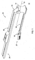
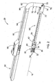
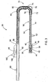
- FIGS. 1-3 depict a medical system 20 for use intracorporeally to assist in surgical procedures beneath a tissue layer 10.
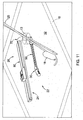
- the tissue layer 10 is typically that of a mammalian patient having a skin layer covering an bodily cavity 12 such as the abdominal or thoracic cavity having various organs 18 ( FIG. 11 ) therein.
- an bodily cavity 12 such as the abdominal or thoracic cavity having various organs 18 ( FIG. 11 ) therein.
- the medical system 20 generally includes a distal portion 22 intended to be utilized beneath the tissue 10 and within the body cavity 12, and a proximal portion 24 intended to reside above the tissue 10 and controlled by the medical professional or other user.
- the distal portion 22 of the medical system 20 generally includes a camera head 30 that is connected to a translating beam 50.
- the beam 50 slidably attaches through a guide sheath 70, part of which is also within the distal portion 22.
- the guide sheath 70 attaches to a handle 90 within the proximal portion 22 of the medical system 20, which -is utilized to orient and control translation of the beam 50 and camera head 30.
- the medical system 20 is generally intended to be used in conjunction with a port 14 positioned within an opening 13 ( FIG. 11 ) in the tissue 10.
- the port 14 has been depicted in FIG. 1 is a simple tubular member that is fitted within the opening 13, although various types of ports utilized in laparoscopic or other minimally invasive surgeries may be employed.
- One preferred port is that disclosed in US Appl. No. 61/564,021 filed November 28, 2011 entitled SURGICAL ACCESS PORT the contents of which are incorporated herein by reference in its entirety.
- the beam 50 is a one-way bending beam which can bend through the angles formed by the guide sheath 70 to allow the system 20 to rotate through the tissue 10 and extend generally in the plane of the tissue 10.
- the beam 50 resists bending in one direction and is oriented relative to the guide sheath such that, as the beam is slid relative to guide sheath, the beam bends in a first direction (generally down on the page in FIGS.
- the beam 50 is a cantilevered beam that is supported at the distal opening of the guide sheath 70.
- the beam 50 resistance to bending 'downward' under the force of gravity, assuming the system 20 and beam 50 are oriented appropriately relative to gravity, e.g. in most abdominal surgeries where the patient is in a supine or semi-supine position.
- the system 20 may be utilized when the patient is in other positions or the system 20 and beam 50 are rotated such that the plane of the first and second directions is not perfectly perpendicular to the ground.
- the apparatus 20, and in particular the handle 90 and guide sheath 70, may also be rotated relative to the port 14 such that the distal port 22 and its camera head 30 sweep through a plane generally parallel to the tissue 10.
- the beam 50 may be extended and retracted distally and proximally to position the camera head 30 within the cavity 12.
- the camera head 30 pivots relative to the beam 50, and preferably provides for both rotation about an axis 16 defined by the beam 50 as well as pivoting about an axis transverse to the axis of the beam 50. Accordingly, the medical system 20 provides 4 degrees of freedom to the camera head 34 for improved visualization and lighting throughout the body cavity 12.
- the camera head 30 generally includes a camera 32 and one or more lighting elements 34. Additional elements such as an electro cautery device 36 or injection ports may be provided within the camera head 30.
- the camera 32 is an HD camera which utilizes laparoscope camera technology having rod-lens imaging and "chip-in-the-tip" imaging. Utilizing rod-lenses, the images from the cameral 32 are captured on a sensor within the camera head 30 or within the handle 90.
- the lighting elements 34 are preferably LED elements and provide illumination via a electrical connection with the handle 90, or are lenses connected to a fiber optic cable carrying light from an external lamp, such as a Zenon arc lamp.
- the camera head 30 generally includes a joint member 38 connecting a distal head 40 to a proximal head portion 42.
- the joint 38 is pivotally connected to the proximal head portion 42, e.g. via a pin, ball-and-socket or other pivotal connection, to allow the joint 38 and the distal head portion 40 to pivot relative to the proximal head portion 42 and beam 50.
- the joint 38 also provides a flange 48 defining a surface about which the distal head portion 40 may rotate about the longitudinal axis of the joint 38 (and often axis 16 as shown).
- the pivoting and rotation of the camera head 30 may be accomplished via appropriately located control wires 44 which pass through an interior passageway 46 of the joint 38 and through the interior of the beam 50.
- the control wires 44 may mechanically transfer energy to the camera head 34 for articulation, or the camera head 30 may include small motors or prime movers (not shown) that are electrically driven via electric control wires 44.
- the beam 50 is generally formed by a plurality of links 52 connected on one side by a flexible strip 54.
- each of the links 52 preferably includes a bore 56 which is aligned with adjacent bores 56 to form an internal passageway through the beam 50 leading between the camera head 30 and the handle 90.
- One or more links 52 at the distal end of the beam 50 is attached to the proximal head portion 42 of the camera head 30.
- the links 52 may be formed of plastic or metal, while the strip 54 is formed of a resilient but flexible material, preferably of nitinol or other biocompatible metal or alloy, although sufficiently resilient plastics can also be used.
- the flexible strip 54 may be attached to the links 52 via an adhesive or using other bonding techniques such as fusion, soldering or welding at appropriate points to provide one-way bending.
- the strip 54 may include lateral slots, preferably at axial positions spaced from the abutting corners of the links, to provide a location for soldering or to control the stiffness and flexibility of the strip 54.
- the links may be attached to the strip 54a by bending small tabs 53a formed in the links, namely bending the tabs 53a through the lateral slots 55a and over the strip 54a thereby locking the links in place.
- the beam 50 does not flex more than 1 to 10 degrees from the straight linear axis 16 depicted in the figures. For example, in FIG.
- an alternate beam 150 (shown from the side) includes a plurality of links 152 which are connected to a plurality of small strips 154.
- the plurality of strips 154 are positioned to extend over the abutting corners 158 defining by the abutting surfaces 160 of adjacent links 152.
- the plurality of strips 154 are flexible such that the lower corners 162 (i.e. those down on the page in FIG. 5 ) may move away from each other while the links 152 general pivot about the other edges 158 which are held together via the strips 154.
- an alternate beam 250 includes a plurality of links 252 that are pivotally connected together at their upper adjacent corners via corresponding tabs and detents 254 which provide a hinge joint.
- FIG. 7 depicts an alternate beam 350 which includes a plurality of links 352 and each are pivotally attached at their upper corners to pins 354 which allow the links 352 to rotate relative to one another about the pins 354.
- the corners of the upper surfaces 356 are rounded (or chamfered, filleted, etc.) to accommodate the rotation, while the links include adjacent abutting surfaces 358 which extend below the pins 354 to prevent bending in the opposite direction (i.e. down on the page).
- the guide sheath 70 is tubular and generally includes a first sheath portion 72 and a second sheath portion 74.
- the first sheath portion is straight and defines a first axis (shown as coincident with axis 16 in FIG. 2 ), and likewise the second sheath portion 74 is generally straight and defines a second axis 75.
- the first sheath portion 72 is rotatable relative to the second sheath portion 74 about a hinge 76 to adjust the angle between the first and second axes.
- a control wire or other control member (not shown) is attached to the first sheath portion at a position distal to the hinge 76 to control articulation of the first sheath portion 72 between an introduction configuration and an operative configuration.
- the first sheath portion 72 In the introduction configuration ( FIG. 8 ) the first sheath portion 72 is generally aligned with the second sheath portion 74 such that the first axis and second axis are generally parallel.
- the first axis is rotated relative to the second axis, preferably between 1 and 135 degrees and most preferably around 90 degrees.
- FIG. 2 also shows that the first sheath portion 72 preferably includes plurality of projecting tabs 73 in an area of the hinge connection that are angularly spaced. The tabs 73 are sized and position engage the second sheath portion 74 (or are otherwise operatively connected thereto) to provide for discrete angular positioning of the first sheath portion 72 relative to the second sheath portion 74.
- a recess 78 is formed in the first sheath portion 72 and a corresponding recess (not shown) in the second sheath portion 74 provides an open space for the beam 50 to pass through a first bend 75 formed between the first and second sheath portions 72, 74.
- a third portion 80 of the guide sheath 70 (at a proximal end thereof) further defines a second bend 82.
- the second bend is fixed, such as by rigidly joining or unitarily forming the second and third sheath portions 74, 80, and is preferably around 90 degrees.
- the second bend could also be a controllable pivoting joint.
- the beam 50 rotates about 90 degrees through the second bend 82, and then rotates another 90 degrees through the first bend 75 such that a distal portion of the beam 50 extends generally parallel to a proximal portion of the beam 50 that is external to the tissue 10 (as with the distal and proximal portions 22, 24 of the system 20 described above).
- a proximal end 50 of the beam is attached to the handle 90.
- the handle 90 generally includes a housing 92 defining a guide rail 94, which has been depicted as a simple slot 94 formed longitudinally through the housing 92.
- a thumb slider 96 slides along the housing 92 guided by the slot 94, and includes a tab 98 projecting through the slot 94 and riding within the housing 92.
- the tab 98 is attached to the proximal end 58 of the beam 50, i.e. to one or more proximal links 52.
- the beam 50 may be moved distally and proximally through the guide sheath 70 and within the body cavity 12.
- the control wires 44 extending from the camera head 30 through the beam 50 also extend through the thumb slider 96 to various controls 100 located on thereon.
- the controls 100 may be operatively connected to a circuit board 102 or other electronic elements for transmitting and storing signals from the camera head 30, or may be attaching to winding wheels, torque wheels, tensioning mechanisms and the like for transmitting mechanical energy through the control wires 44 (e.g. for rotation of the camera 32).
- FIGS. 8-10 operation of the medical system 20 will be described.
- the medical system 20 is shown in the introduction configuration where the thumb slider 96 of the handle 90 is moved proximally (to the left on the page) to retract the beam 50.
- the beam 50 extends through the second bend 82 of the guide sheath 70 and through both the first and second sheath portions 72, 74 which are generally parallel.
- the angle of the second bend 82, the angle of the first bend 75 (which can be greater than zero in the introduction configuration), and the size of the first and second sheath portions 72, 74 are configured relative to one another to allow the distal portion 22 of the medical system 20 to pass through the opening in the port 14 (or directly through the opening 13 in tissue 10.
- the first sheath section 72 may be rotated relative to the second sheath portion 74 such that the guide sheath 70 forms the second bend 75, as shown in FIG. 9 .
- Rotation of the first sheath section 72 causes the distal end of the beam 50 to be rotated a total of about 180 degrees relative to the proximal portion residing in the handle 90. In this position, the entire handle assembly 90 may be rotated about a plane of the tissue 10 and the camera head 30 rotated or pivoted to initially identify the structures within the cavity 12.
- the beam 50 may be slid through the guide sheath and distally projected as shown in FIG. 10 .
- the beam 50 and camera head 30 project beyond a distal end of the guide sheath 70 and further into the cavity 12.
- additional instruments 125 may be passed through the port 14 or through other access points into the cavity 12 for performing surgery such as a laparoscopic or other minimally invasive surgery.
- the medical system 20 provides a means for introducing a distal section 22 of the device within the bodily cavity 12 while a proximal portion of the device 24 remains above the tissue 10 while the two portions 22, 24 are generally parallel to one another.
- This configuration is relatively unobtrusive to other instruments, and provides complete viewing of the cavity 12 by providing the camera 32 with 3 or 4 degrees of freedom.
- One of the advantages of the system 20 is that the camera 30 is moved away from the immediate vicinity of the operating field and other instruments, so that the instruments may be viewed from a side-view rather than head-on. This is likely to be an ideal perspective for operative visualization.
- the guide sheath 70 is generally depicted as performing a U-turn or bend in the operative configuration, it will be recognized that the pivotal connection between the first and second sheath portions 72, 74 can be such that the beam 50 is not coplanar with the handle 90 or the portion of the beam therein, or such that the beam 50 follows one or more bends that form an S-shape or Z-turn.
- the camera head 30 is provided with 4 degrees of freedom to find the best position within the cavity 12 to navigate around adjacent structures to illuminate and visualize an organ or other bodily structure 18 within the cavity 12, while still providing sufficient space for additional medical instruments 125 to be inserted through the opening 13 and the tissue 10 for operation on the same bodily structure 18.
- the articulation of the camera head 30 allows any degree of triangulation between the additional instruments and the camera head pointing towards the target. Accordingly, the medical system 20 is especially adapted for minimally invasive surgery which utilizes a single incision or single port.
- the camera head 30 includes side viewing camera 32, although it can also be provided at the distal end of the distal housing 40.
- control wires 44 need not extend through the beam 50, and could be provided alongside the exterior of the beam 50 such that the plurality of links 52 may be solid.
- the thumb slider 96 could be motorized, and further be electrically connected to a computer with proper software to control articulation of the slider 96 and translation of the beam 50, as well as both mechanical and electrical control over camera head 30 and receipt of its visual information.
- the systems, devices and methods may be used on any layer of material (e.g. fabrics, cloth, polymers, elastomers, plastics and rubber) that may or may not be associated with a human or animal body and a bodily lumen.
- the systems, devices and methods can find use in laboratory and industrial settings for placing devices through one or more layers of material that may or may not find application to the human or animal body, and likewise closing holes or perforations in layers of material that are not bodily tissue.
- Some examples include viewing behind structures such as walls, plates, floors, rubble (e.g. in rescue work), as well as working with synthetic tissues, polymeric sheets, animal studies, veterinary applications, and post-mortem activities.
Landscapes
- Health & Medical Sciences (AREA)
- Life Sciences & Earth Sciences (AREA)
- Surgery (AREA)
- General Health & Medical Sciences (AREA)
- Public Health (AREA)
- Veterinary Medicine (AREA)
- Nuclear Medicine, Radiotherapy & Molecular Imaging (AREA)
- Animal Behavior & Ethology (AREA)
- Molecular Biology (AREA)
- Engineering & Computer Science (AREA)
- Biomedical Technology (AREA)
- Heart & Thoracic Surgery (AREA)
- Medical Informatics (AREA)
- Pathology (AREA)
- Biophysics (AREA)
- Radiology & Medical Imaging (AREA)
- Physics & Mathematics (AREA)
- Optics & Photonics (AREA)
- Rehabilitation Therapy (AREA)
- Endoscopes (AREA)
- Surgical Instruments (AREA)
Claims (20)
- Medizinisches System (20) für den intrakorporalen Gebrauch zum Assistieren bei chirurgischen Verfahren unter einer Gewebeschicht (10), wobei das System (20) umfasst:eine Kamera (32);einen Ausleger (50), der ein distales Ende aufweist, das an der Kamera (32) befestigt ist;einen Führungsmantel (70), der derart ausgebildet ist, dass er den Ausleger (50) verschiebbar aufnimmt, wobei sich der Ausleger (50) durch ein distales Ende des Führungsmantels (70) erstreckt, so dass die Kamera (32) von dem distalen Ende des Führungsmantels (70) abragt, wobei der Führungsmantel (70) einen ersten Mantelabschnitt (72), der eine erste Achse definiert, und einen zweiten Mantelabschnitt (74), der eine zweite Achse definiert, aufweist, wobei der Führungsmantel (70) eine operative Konfiguration aufweist, in der der erste Mantelabschnitt (72) relativ zu dem zweiten Mantelabschnitt (74) abgewinkelt ist, um eine erste Krümmung (75) zu definieren;dadurch gekennzeichnet, dassder Ausleger (50) derart ausgebildet ist, dass er in einer ersten Richtung biegbar ist und dass er sich in einer zweiten Richtung, die der ersten entgegengesetzt ist, nicht biegen lässt;sich der Ausleger (50) durch den ersten Mantelabschnitt (72) und durch den zweiten Mantelabschnitt (74) erstreckt; undder Ausleger (50) relativ zu dem Führungsmantel (70) so ausgerichtet ist, dass sich der Ausleger (50) durch die erste Krümmung (75) in die erste Richtung krümmt, wenn der Ausleger (50) relativ zu dem Führungsmantel (70) verschoben wird, und dass ein abragender Abschnitt des Auslegers (50), der von dem distalen Ende des Führungsmantels (70) abragt, sich nicht in der zweiten Richtung biegen lässt.
- Medizinisches System (20) nach Anspruch 1, wobei der Ausleger (50) einem Biegen genügend Widerstand entgegenbringt, so dass er sich nicht unter seinem eigenen Gewicht und unter dem Gewicht der Kamera (32) biegt.
- Medizinisches System (20) nach Anspruch 1, wobei der Ausleger (50) einem Biegen genügend Widerstand entgegenbringt, so dass der abragende Abschnitt des Auslegers (50) eine Auslegerachse definiert, die sich linear von dem distalen Ende des Führungsmantels (70) erstreckt.
- Medizinisches System (20) nach Anspruch 1, wobei der Ausleger (50) aus einer Mehrzahl an Gliedern (52) gebildet ist, die miteinander verbunden sind, um eine Relativrotation zwischen aneinandergrenzenden Gliedern (52) zu erlauben.
- Medizinisches System (20) nach Anspruch 4, wobei die Glieder (52) durch ein biegbares Band (54) an einer ersten Seite jedes Gliedes (52) miteinander verbunden sind.
- Medizinisches System (20) nach Anspruch 4, wobei die Glieder (52) an ihren Enden gelenkig miteinander verbunden sind, wobei die Enden eine Endoberfläche definieren, die derart ausgebildet ist, dass sie eine Rotation von aneinandergrenzenden Gliedern relativ zueinander in der ersten Richtung zulässt, jedoch eine Rotation von aneinandergrenzenden Gliedern (52) aufeinander zu in der zweiten Richtung einschränkt.
- Medizinisches System (20) nach Anspruch 4, wobei die Endoberflächen Abrundungen definieren, wobei eine erste Seitenoberfläche in Richtung der ersten Richtung angeordnet ist.
- Medizinisches System (20) nach Anspruch 1, wobei der Ausleger (50) hohl ist, um einen Durchgang (56) zu definieren, der sich zu dem distalen Ende des Auslegers (50) hin erstreckt, und wobei das System weiterhin ein Steuerkabel (44) umfasst, das sich durch den Durchgang (56) hindurch erstreckt und operativ mit der Kamera (32) verbunden ist.
- Medizinisches System (20) nach Anspruch 1, wobei die erste Krümmung (75) durch den ersten Mantelabschnitt (72) gebildet ist, der relativ zu dem zweiten Mantelabschnitt (74) um in etwa 90° abgewinkelt ist.
- Medizinisches System (20) nach Anspruch 1, wobei der erste Mantelabschnitt (72) drehbar an dem zweiten Mantelabschnitt (74) befestigt ist.
- Medizinisches System (20) nach Anspruch 10, wobei der Führungsmantel (70) eine Einführkonfiguration aufweist, bei der der erste Mantelabschnitt (72) im Allgemeinen parallel zu dem zweiten Mantelabschnitt (74) ist.
- Medizinisches System (20) nach Anspruch 1, wobei der erste Mantelabschnitt (72) so betätigbar ist, dass er sich relativ zu dem zweiten Mantelabschnitt (74) in einem Bogen von in etwa 90° bis in etwa 135° dreht.
- Medizinisches System (20) nach Anspruch 1, weiterhin mit einem dritten Mantelabschnitt (80), der relativ zu dem zweiten Abschnitt (74) abgewinkelt ist, um eine zweite Krümmung (82) zu definieren.
- Medizinisches System (20) nach Anspruch 13, wobei die zweite Krümmung (82) einen festen Winkel definiert.
- Medizinisches System (20) nach Anspruch 13, wobei die erste und die zweite Krümmung (75, 82) in der operativen Konfiguration so angeordnet sind, dass der Ausleger (50) um 180° gebogen wird, so dass ein proximaler Auslegerabschnitt in etwa parallel zu einem distalen Auslegerabschnitt ist.
- Medizinisches System (20) nach Anspruch 1, weiterhin mit einem Kamerakopf (30), der die Kamera (32) trägt und an dem distalen Ende des Auslegers (50) befestigt ist, wobei der Kamerakopf (30) einen proximalen Kopfabschnitt (42), der an dem Ausleger (50) befestigt ist, und einen distalen Kopfabschnitt (40), der drehbar an dem proximalen Kopfabschnitt (42) befestigt ist, umfasst.
- Medizinisches System (20) nach Anspruch 16, wobei sich der distale Kopfabschnitt (40) um eine Drehachse dreht, so dass der distale Kopfabschnitt (40) relativ zu dem proximalen Kopfabschnitt (42) abgewinkelt ist.
- Medizinisches System (20) nach Anspruch 17, wobei die Drehachse senkrecht zu einer Längsachse eines abragenden Abschnitts des Auslegers (50) ist, der von dem Führungsmantel (70) abragt.
- Medizinisches System (20) nach Anspruch 16, wobei sich der distale Kopfabschnitt (40) um eine Drehachse dreht, wobei die Drehachse in etwa parallel zu einer Längsachse eines abragenden Abschnitts des Auslegers (50) ist, der von dem Führungsmantel (70) abragt.
- Medizinisches System (20) nach Anspruch 19, weiterhin mit einem mittleren Kopfabschnitt, der den proximalen und den distalen Kopfabschnitt (40, 42) miteinander verbindet, wobei der mittlere Kopfabschnitt relativ zu einem von dem proximalen oder distalen Kopfabschnitt (40, 42) um eine erste Drehachse drehbar ist, so dass der distale Kopfabschnitt (40) relativ zu dem proximalen Kopfabschnitt (42) abgewinkelt ist, und wobei der mittlere Kopfabschnitt bezüglich dem anderen von proximalem oder distalem Kopfabschnitt (40, 42) um eine zweite Drehachse drehbar ist, die in etwa parallel zu einer Längsachse eines abragenden Abschnitts des Auslegers (50) ist, der von dem Führungsmantel (70) abragt.
Applications Claiming Priority (1)
| Application Number | Priority Date | Filing Date | Title |
|---|---|---|---|
| US13/408,640 US9339264B2 (en) | 2010-10-01 | 2012-02-29 | Port access visualization platform |
Publications (2)
| Publication Number | Publication Date |
|---|---|
| EP2633799A1 EP2633799A1 (de) | 2013-09-04 |
| EP2633799B1 true EP2633799B1 (de) | 2014-11-05 |
Family
ID=46637401
Family Applications (1)
| Application Number | Title | Priority Date | Filing Date |
|---|---|---|---|
| EP13155705.0A Active EP2633799B1 (de) | 2012-02-29 | 2013-02-19 | Plattform zur Visualisierung des Portzugangs |
Country Status (4)
| Country | Link |
|---|---|
| US (2) | US9339264B2 (de) |
| EP (1) | EP2633799B1 (de) |
| JP (1) | JP5666638B2 (de) |
| AU (1) | AU2013201155B2 (de) |
Families Citing this family (19)
| Publication number | Priority date | Publication date | Assignee | Title |
|---|---|---|---|---|
| US8888792B2 (en) | 2008-07-14 | 2014-11-18 | Ethicon Endo-Surgery, Inc. | Tissue apposition clip application devices and methods |
| AU2010300449A1 (en) * | 2009-10-02 | 2012-05-03 | Cook Medical Technologies Llc | Endoscopic fascia tunneling |
| US9339264B2 (en) * | 2010-10-01 | 2016-05-17 | Cook Medical Technologies Llc | Port access visualization platform |
| US9427255B2 (en) | 2012-05-14 | 2016-08-30 | Ethicon Endo-Surgery, Inc. | Apparatus for introducing a steerable camera assembly into a patient |
| US10098527B2 (en) * | 2013-02-27 | 2018-10-16 | Ethidcon Endo-Surgery, Inc. | System for performing a minimally invasive surgical procedure |
| DE102013211698B4 (de) * | 2013-06-20 | 2017-07-06 | Fraunhofer-Gesellschaft zur Förderung der angewandten Forschung e.V. | Endoabdominales Kamerasystem |
| US10849483B2 (en) | 2014-09-15 | 2020-12-01 | Vivid Medical, Inc. | Single-use, port deployable articulating endoscope |
| CN104939800B (zh) * | 2015-06-16 | 2017-04-05 | 西南医科大学附属医院 | 一种肠胃自动检测手术仪 |
| US10850046B2 (en) * | 2016-03-28 | 2020-12-01 | Becton, Dickinson And Company | Cannula locator device |
| ES2730387B2 (es) * | 2018-05-09 | 2020-10-01 | Tristan Andres Del Amor Arroyo | Cabezal de videocamara endoscopica anexable a protector de herida quirurgica, sin tubo rigido ni sujecion manual |
| WO2019215354A1 (es) * | 2018-05-09 | 2019-11-14 | Andres Del Amor Arroyo Tristan | Cabezal de videocámara endoscópica anexable a protector de herida quirúrgica, sin tubo rígido ni sujeción manual |
| US20240349992A1 (en) * | 2019-01-30 | 2024-10-24 | Momentis Surgical Ltd. | Imaging device with elongate arm and pivotable camera |
| JP7256848B2 (ja) * | 2019-04-04 | 2023-04-12 | グリー株式会社 | プログラム、制御方法、及びコンピュータ |
| EP4099009A4 (de) * | 2020-01-30 | 2023-08-30 | Mitsubishi Heavy Industries, Ltd. | Vorrichtung und verfahren zur zerstörungsfreien prüfung |
| DE102020132776A1 (de) * | 2020-12-09 | 2022-06-09 | Karl Storz Se & Co. Kg | Hybridendoskop mit Rotationstrommel für sterile medizinische Anwendungen |
| EP4066770A1 (de) * | 2021-04-02 | 2022-10-05 | Robeaute | Liefer- und sammelsystem mit einem mikroroboter |
| US20240033020A1 (en) * | 2020-12-16 | 2024-02-01 | Robeaute | Delivery and gathering system comprising a microrobot |
| US20220395171A1 (en) * | 2021-06-15 | 2022-12-15 | Arthrex, Inc. | Surgical camera system |
| US12259086B2 (en) * | 2022-11-23 | 2025-03-25 | Becton, Dickinson And Company | Adjustable image capture device |
Family Cites Families (165)
| Publication number | Priority date | Publication date | Assignee | Title |
|---|---|---|---|---|
| US11025A (en) * | 1854-06-06 | litta | ||
| US3677262A (en) | 1970-07-23 | 1972-07-18 | Henry J Zukowski | Surgical instrument illuminating endotracheal tube inserter |
| US3690775A (en) * | 1971-09-01 | 1972-09-12 | Avco Corp | Borescope fixture |
| US3778170A (en) * | 1972-11-02 | 1973-12-11 | Gen Electric | Borescope guide tube |
| US3858577A (en) | 1974-04-05 | 1975-01-07 | Univ Southern California | Fiber optic laser light delivery system |
| JPS5552747A (en) | 1978-10-12 | 1980-04-17 | Tokyo Ika Shika Daigakuchiyou | Medical appliance holding instrument |
| US4222382A (en) * | 1979-01-26 | 1980-09-16 | Massachusetts Institute Of Technology | Femoral component hip joint prosthesis extractor |
| US4254763A (en) | 1979-06-07 | 1981-03-10 | Codman & Shurtleff, Inc. | Surgical retractor assembly |
| GB2147210B (en) | 1983-09-28 | 1986-12-17 | Wolf Gmbh Richard | An endoscope |
| US4640124A (en) * | 1984-02-16 | 1987-02-03 | Richard Wolf Gmbh | Tecnoscopes |
| US4640273A (en) | 1985-05-08 | 1987-02-03 | E-Z-Em, Inc. | Mouth guard for use with a diagnostic instrument |
| JPH0546406Y2 (de) * | 1988-07-20 | 1993-12-06 | ||
| US4911148A (en) * | 1989-03-14 | 1990-03-27 | Intramed Laboratories, Inc. | Deflectable-end endoscope with detachable flexible shaft assembly |
| US5643221A (en) * | 1990-05-04 | 1997-07-01 | Bullard; James Roger | Controlled targeting laryngoscope |
| US5133336A (en) * | 1990-10-22 | 1992-07-28 | Endoscopy Support Services, Inc. | Disposable liquid supply system for use in an endoscope |
| US5716327A (en) | 1991-05-29 | 1998-02-10 | Origin Medsystems, Inc. | Body wall retraction system for wide cavity retraction |
| MX9202604A (es) | 1991-05-29 | 1994-05-31 | Origin Medsystems Inc | Aparato para la retraccion properitoneal mecanica y metodos de empleo. |
| US5571215A (en) | 1993-02-22 | 1996-11-05 | Heartport, Inc. | Devices and methods for intracardiac procedures |
| JPH05123287A (ja) * | 1991-11-08 | 1993-05-21 | Olympus Optical Co Ltd | 保護シース |
| JP3147318B2 (ja) * | 1992-08-26 | 2001-03-19 | オリンパス光学工業株式会社 | 前方スキャン型体内用超音波プローブ |
| US5469853A (en) | 1992-12-11 | 1995-11-28 | Tetrad Corporation | Bendable ultrasonic probe and sheath for use therewith |
| US5547458A (en) | 1994-07-11 | 1996-08-20 | Ethicon, Inc. | T-shaped abdominal wall lift with telescoping member |
| US5522788A (en) * | 1994-10-26 | 1996-06-04 | Kuzmak; Lubomyr I. | Finger-like laparoscopic blunt dissector device |
| US5512035A (en) * | 1994-10-27 | 1996-04-30 | Circon Corporation, A Delaware Corporation | Cable compensating mechanism for an endoscope |
| US5749889A (en) | 1996-02-13 | 1998-05-12 | Imagyn Medical, Inc. | Method and apparatus for performing biopsy |
| CA2197614C (en) | 1996-02-20 | 2002-07-02 | Charles S. Taylor | Surgical instruments and procedures for stabilizing the beating heart during coronary artery bypass graft surgery |
| US5913818A (en) | 1997-06-02 | 1999-06-22 | General Surgical Innovations, Inc. | Vascular retractor |
| US6196968B1 (en) * | 1997-06-02 | 2001-03-06 | General Surgical Innovations, Inc. | Direct vision subcutaneous tissue retractor and method for use |
| JP4121615B2 (ja) | 1997-10-31 | 2008-07-23 | オリンパス株式会社 | 内視鏡 |
| US5976075A (en) * | 1997-12-15 | 1999-11-02 | University Of Massachusetts | Endoscope deployment apparatus |
| DE19906191A1 (de) | 1999-02-15 | 2000-08-17 | Ingo F Herrmann | Endoskop |
| CA2286929A1 (en) | 1999-10-18 | 2001-04-18 | Anthony Paolitto | Valve surgery apparatus |
| US6530929B1 (en) | 1999-10-20 | 2003-03-11 | Sdgi Holdings, Inc. | Instruments for stabilization of bony structures |
| US6416469B1 (en) | 2000-01-26 | 2002-07-09 | Genzyme Corporation | Suture organizing and retaining device and base member for surgical retractor |
| US6235028B1 (en) | 2000-02-14 | 2001-05-22 | Sdgi Holdings, Inc. | Surgical guide rod |
| US6539942B2 (en) * | 2001-04-19 | 2003-04-01 | Richard Schwartz | Endotracheal intubation device |
| US6528908B1 (en) * | 2001-10-09 | 2003-03-04 | Rick Lee | Induction drive for induction driven conveyor including a virtual continuous magnetic body and method of driving induction driven conveyor including a virtual continuous magnetic body |
| US20050059934A1 (en) | 2003-04-25 | 2005-03-17 | Thomas Wenchell | Surgical access apparatus |
| US7431694B2 (en) | 2003-05-16 | 2008-10-07 | Ethicon Endo-Surgery, Inc. | Method of guiding medical devices |
| US7815565B2 (en) | 2003-05-16 | 2010-10-19 | Ethicon Endo-Surgery, Inc. | Endcap for use with an endoscope |
| US7615003B2 (en) | 2005-05-13 | 2009-11-10 | Ethicon Endo-Surgery, Inc. | Track for medical devices |
| JP3521910B1 (ja) | 2003-05-29 | 2004-04-26 | 清輝 司馬 | 内視鏡の外部鉗子チャンネル装置 |
| US7753901B2 (en) | 2004-07-21 | 2010-07-13 | Tyco Healthcare Group Lp | Laparoscopic instrument and cannula assembly and related surgical method |
| JP2008504051A (ja) | 2004-04-05 | 2008-02-14 | タイコ ヘルスケア グループ リミテッド パートナーシップ | 外科手術用ハンドアクセス装置 |
| US20070167682A1 (en) * | 2004-04-21 | 2007-07-19 | Acclarent, Inc. | Endoscopic methods and devices for transnasal procedures |
| US7658738B2 (en) | 2004-05-14 | 2010-02-09 | Ethicon Endo-Surgery, Inc. | Medical devices for use with endoscope |
| US8328810B2 (en) | 2004-06-17 | 2012-12-11 | Boston Scientific Scimed, Inc. | Slidable sheaths for tissue removal devices |
| ES2433664T3 (es) * | 2004-06-25 | 2013-12-12 | Carnegie Mellon University | Dispositivo guiador dirigible |
| JP4302602B2 (ja) | 2004-09-24 | 2009-07-29 | オリンパス株式会社 | 内視鏡用処置具及び内視鏡処置システム並びに支持アダプタ |
| US7963976B2 (en) * | 2004-11-04 | 2011-06-21 | Dynamic Surgical Inventions, Llc | Articulated surgical probe and method for use |
| FR2879914B1 (fr) | 2004-12-24 | 2007-03-09 | Protomed Sarl | Ecarteur-retenteur d'intestins pour chirurgie coelioscopique |
| JP4477519B2 (ja) | 2005-02-14 | 2010-06-09 | オリンパス株式会社 | 内視鏡 |
| US7766810B2 (en) | 2005-03-10 | 2010-08-03 | Olympus Medical Systems Corp. | Probing method and holding method for luminal organ |
| US7717878B2 (en) | 2005-04-25 | 2010-05-18 | Tyco Healthcare Group Lp | Surgical portal with seal system |
| US20080319258A1 (en) | 2005-07-15 | 2008-12-25 | Thompson Christopher C | Sterile Access Conduit |
| EP1759629B1 (de) * | 2005-08-31 | 2014-04-02 | Karl Storz GmbH & Co. KG | Endoskop mit variabler Blickrichtung |
| CA2630215A1 (en) * | 2005-11-17 | 2007-05-24 | Micromuscle Ab | Medical devices and methods for their fabrication and use |
| US7520879B2 (en) | 2006-02-07 | 2009-04-21 | Warsaw Orthopedic, Inc. | Surgical instruments and techniques for percutaneous placement of spinal stabilization elements |
| EP1989990B1 (de) * | 2006-02-27 | 2014-06-04 | Olympus Medical Systems Corp. | Endoskopisches chirurgiegerät |
| US20070213754A1 (en) | 2006-03-08 | 2007-09-13 | Olympus Medical Systems Corp. | Incision instrument, incision apparatus, and organ incision method |
| US20100081863A1 (en) | 2008-09-30 | 2010-04-01 | Ethicon Endo-Surgery, Inc. | Methods and devices for performing gastrectomies and gastroplasties |
| US8961406B2 (en) | 2009-03-06 | 2015-02-24 | Ethicon Endo-Surgery, Inc. | Surgical access devices and methods providing seal movement in predefined movement regions |
| US8357085B2 (en) | 2009-03-31 | 2013-01-22 | Ethicon Endo-Surgery, Inc. | Devices and methods for providing access into a body cavity |
| US8206294B2 (en) | 2008-09-30 | 2012-06-26 | Ethicon Endo-Surgery, Inc. | Surgical access device with flexible seal channel |
| US8425410B2 (en) | 2008-09-30 | 2013-04-23 | Ethicon Endo-Surgery, Inc. | Surgical access device with protective element |
| US8821391B2 (en) | 2009-03-06 | 2014-09-02 | Ethicon Endo-Surgery, Inc. | Methods and devices for providing access into a body cavity |
| US20100081883A1 (en) | 2008-09-30 | 2010-04-01 | Ethicon Endo-Surgery, Inc. | Methods and devices for performing gastroplasties using a multiple port access device |
| US8251900B2 (en) | 2009-03-06 | 2012-08-28 | Ethicon Endo-Surgery, Inc. | Surgical access devices and methods providing seal movement in predefined paths |
| US8926506B2 (en) | 2009-03-06 | 2015-01-06 | Ethicon Endo-Surgery, Inc. | Methods and devices for providing access into a body cavity |
| US20100228096A1 (en) | 2009-03-06 | 2010-09-09 | Ethicon Endo-Surgery, Inc. | Methods and devices for providing access into a body cavity |
| US8485970B2 (en) | 2008-09-30 | 2013-07-16 | Ethicon Endo-Surgery, Inc. | Surgical access device |
| US8430811B2 (en) | 2008-09-30 | 2013-04-30 | Ethicon Endo-Surgery, Inc. | Multiple port surgical access device |
| DE102006016845B3 (de) * | 2006-04-07 | 2007-08-30 | Olympus Winter & Ibe Gmbh | Medizinisches Videoendoskop mit abwinkelbarem Endteil |
| US20070244362A1 (en) * | 2006-04-12 | 2007-10-18 | Roger El-Hachem | Segmented colonoscope |
| WO2007130382A2 (en) | 2006-04-29 | 2007-11-15 | Board Of Regents, The University Of Texas System | Devices for use in transluminal and endoluminal surgery |
| US7841980B2 (en) | 2006-05-11 | 2010-11-30 | Olympus Medical Systems Corp. | Treatment system, trocar, treatment method and calibration method |
| WO2008006114A2 (en) | 2006-07-07 | 2008-01-10 | Fred Kessler | Channeled flexible sleeve for medical articles |
| DE102006000399A1 (de) * | 2006-08-10 | 2008-02-14 | Novineon Healthcare Technology Partners Gmbh | Medizinisches Instrument |
| JP5226197B2 (ja) * | 2006-08-25 | 2013-07-03 | オリンパス株式会社 | 内視鏡用ガイドチューブ及び内視鏡装置 |
| US7806870B2 (en) | 2006-10-06 | 2010-10-05 | Surgiquest, Incorporated | Elastically deformable surgical access device having telescoping guide tube |
| US7798998B2 (en) | 2006-10-06 | 2010-09-21 | Surgiquest, Inc. | Elastically deformable surgical access device |
| US7976458B2 (en) * | 2006-12-05 | 2011-07-12 | Ethicon Endo-Surgery, Inc. | Independent articulating accessory channel |
| US20080208001A1 (en) * | 2007-02-26 | 2008-08-28 | Ron Hadani | Conforming endoscope |
| WO2008115505A1 (en) | 2007-03-21 | 2008-09-25 | The Trustees Of The University Of Pennsylvania | Natural orifice transluminal endoscopic surgery overtube and method of introducing multiple endoscopes |
| JP5021346B2 (ja) * | 2007-03-23 | 2012-09-05 | オリンパス株式会社 | 内視鏡用ガイドチューブ及び内視鏡装置 |
| WO2008127886A1 (en) | 2007-04-11 | 2008-10-23 | Tyco Healthcare Group Lp | Endoscopic/laparoscopic introducer sleeve |
| JP2008259701A (ja) | 2007-04-12 | 2008-10-30 | Olympus Corp | 生体内挿入器具 |
| JP2008284107A (ja) | 2007-05-16 | 2008-11-27 | Olympus Corp | 体腔内挿入具案内器具及び体腔内挿入具案内システム |
| US20080287743A1 (en) | 2007-05-17 | 2008-11-20 | Boston Scientific Scimed, Inc. | Medical retractor and stabilizing assembly and related methods of use |
| AU2008255056A1 (en) * | 2007-05-18 | 2008-11-27 | Boston Scientific Limited | Articulating torqueable hollow device |
| JP5575375B2 (ja) | 2007-05-22 | 2014-08-20 | コヴィディエン リミテッド パートナーシップ | 可変調節性を有する外科用ポータル装置 |
| US7762990B2 (en) | 2007-05-24 | 2010-07-27 | Tyco Healthcare Group Lp | Surgical access apparatus with centering mechanism |
| US7967842B2 (en) | 2007-06-01 | 2011-06-28 | Ethicon Endo-Surgery, Inc. | Integrated securement and closure apparatus |
| US20090054728A1 (en) | 2007-08-21 | 2009-02-26 | Trusty Robert M | Manipulatable guide system and methods for natural orifice translumenal endoscopic surgery |
| GB0716672D0 (en) * | 2007-08-28 | 2007-10-03 | Aircraft Medical Ltd | Laryngoscope |
| EP2194834A2 (de) | 2007-09-24 | 2010-06-16 | Jetprep Ltd. | Virtuelle kanal-aktivierungsvorrichtung zur verwendung bei der einführung eines endoskopischen instruments und zur renigung von körperhöhlen |
| WO2009048542A2 (en) | 2007-10-05 | 2009-04-16 | Boston Scientific Scimed, Inc. | Transluminal endoscopic surgery kit |
| US7553227B2 (en) | 2007-10-31 | 2009-06-30 | Cnh America Llc | Residue splitter |
| US20090149714A1 (en) | 2007-12-05 | 2009-06-11 | Frank Bonadio | Surgical devices and methods |
| US8118783B2 (en) | 2008-01-30 | 2012-02-21 | Tyco Healthcare Group Lp | Access assembly with spherical valve |
| US20090259172A1 (en) | 2008-04-09 | 2009-10-15 | Koji Yamaoka | Over tube |
| US10350050B2 (en) | 2008-05-01 | 2019-07-16 | Ethicon Endo-Surgery, Inc. | Method for gastric volume reduction surgery |
| JP5336760B2 (ja) | 2008-05-01 | 2013-11-06 | オリンパスメディカルシステムズ株式会社 | 内視鏡システム |
| US8197504B2 (en) | 2008-05-01 | 2012-06-12 | Ethicon Endo-Surgery, Inc. | Safe tissue puncture device |
| US20100010298A1 (en) | 2008-07-14 | 2010-01-14 | Ethicon Endo-Surgery, Inc. | Endoscopic translumenal flexible overtube |
| US8262563B2 (en) | 2008-07-14 | 2012-09-11 | Ethicon Endo-Surgery, Inc. | Endoscopic translumenal articulatable steerable overtube |
| US8951226B2 (en) | 2008-08-20 | 2015-02-10 | Chest Innovations, Inc. | Mediastinoscopy access, sampling, and visualization kit featuring toroidal balloons and exotracheal method of using |
| US8328761B2 (en) | 2008-09-30 | 2012-12-11 | Ethicon Endo-Surgery, Inc. | Variable surgical access device |
| US8337394B2 (en) | 2008-10-01 | 2012-12-25 | Ethicon Endo-Surgery, Inc. | Overtube with expandable tip |
| US20100168522A1 (en) | 2008-10-23 | 2010-07-01 | Thomas Wenchell | Surgical access assembly |
| US20100114033A1 (en) | 2008-11-06 | 2010-05-06 | Tyco Healthcare Group Lp | Surgical access device |
| US20100331622A2 (en) | 2008-11-25 | 2010-12-30 | Ethicon Endo-Surgery, Inc. | Tissue manipulation devices |
| DE202008015763U1 (de) * | 2008-11-27 | 2010-04-08 | Q Medical International Ag | Instrument für die laparoskopische Chirurgie |
| EP2194624A1 (de) * | 2008-12-02 | 2010-06-09 | Swisscom AG | Einzieheinrichtung für ein Kabel in ein bestehendes Rohrnetz |
| US20100152539A1 (en) | 2008-12-17 | 2010-06-17 | Ethicon Endo-Surgery, Inc. | Positionable imaging medical devices |
| US8348834B2 (en) | 2008-12-18 | 2013-01-08 | Ethicon Endo-Surgery, Inc. | Steerable surgical access devices and methods |
| US8425406B2 (en) | 2008-12-19 | 2013-04-23 | Boston Scientific Scimed, Inc. | Systems and methods for directing instruments to varying positions at the distal end of a guide tube |
| JP5276998B2 (ja) * | 2009-01-08 | 2013-08-28 | オリンパス株式会社 | 内視鏡挿入補助具 |
| US7988669B2 (en) | 2009-02-17 | 2011-08-02 | Tyco Healthcare Group Lp | Port fixation with filament actuating member |
| US20100210912A1 (en) | 2009-02-17 | 2010-08-19 | Tyco Healthcare Group Lp | Access port with suture management system including flapper with inserts |
| US20100211084A1 (en) | 2009-02-18 | 2010-08-19 | Tyco Healthcare Group Lp | Suture management system for surgical portal apparatus including numbered clips |
| US9737334B2 (en) | 2009-03-06 | 2017-08-22 | Ethicon Llc | Methods and devices for accessing a body cavity |
| US20100228090A1 (en) | 2009-03-06 | 2010-09-09 | Ethicon Endo-Surgery, Inc. | Methods and devices for providing access into a body cavity |
| US7857789B2 (en) | 2009-03-10 | 2010-12-28 | Tyco Healthcare Group Lp | Port fixation using expandable threads |
| US20100234688A1 (en) | 2009-03-10 | 2010-09-16 | Tyco Healthcare Group Lp | Access port including multi-layer seal and suture parks |
| US8177754B2 (en) | 2009-03-19 | 2012-05-15 | Tyco Healthcare Group Lp | Surgical port seal |
| US8574153B2 (en) | 2009-03-20 | 2013-11-05 | Covidien Lp | Flexible port seal |
| US20100249810A1 (en) | 2009-03-24 | 2010-09-30 | Tyco Healthcare Group Lp | Suture management system for surgical portal apparatus including slotted ring |
| US20100249498A1 (en) | 2009-03-24 | 2010-09-30 | Tyco Healthcare Group Lp | Endoscopic Apparatus for Manipulating Tissue |
| US8206357B2 (en) | 2009-03-26 | 2012-06-26 | Tyco Healthcare Group Lp | Articulating surgical portal apparatus with spring |
| US20100249709A1 (en) | 2009-03-27 | 2010-09-30 | Tyco Healthcare Group Lp | Surgical access assembly including shield member |
| US7938804B2 (en) | 2009-03-30 | 2011-05-10 | Tyco Healthcare Group Lp | Surgical access apparatus with seal and closure valve assembly |
| US8449459B2 (en) | 2009-03-31 | 2013-05-28 | Covidien Lp | Access portal including silicone foam three layer seal |
| US8353825B2 (en) | 2009-04-02 | 2013-01-15 | Covidien Lp | Access portal including sponge |
| US8257251B2 (en) * | 2009-04-08 | 2012-09-04 | Ethicon Endo-Surgery, Inc. | Methods and devices for providing access into a body cavity |
| US8419635B2 (en) | 2009-04-08 | 2013-04-16 | Ethicon Endo-Surgery, Inc. | Surgical access device having removable and replaceable components |
| US20100261976A1 (en) | 2009-04-14 | 2010-10-14 | Tyco Healthcare Group Lp | Apparatus and System for Performing Surgery |
| US20100261969A1 (en) | 2009-04-14 | 2010-10-14 | Tyco Healthcare Group Lp | Vibrating seal for a surgical trocar apparatus |
| US20100268162A1 (en) | 2009-04-15 | 2010-10-21 | Ethicon Endo-Surgery, Inc. | Cannula with sealing elements |
| US20100274093A1 (en) | 2009-04-22 | 2010-10-28 | Ethicon Endo-Surgery, Inc. | Methods and devices for identifying sealing port size |
| US20100286478A1 (en) | 2009-04-23 | 2010-11-11 | Usgi Medical, Inc. | Flexible surgery access systems |
| US20100280327A1 (en) | 2009-05-04 | 2010-11-04 | Ethicon Endo-Surgery, Inc. | Methods and devices for providing access through tissue to a surgical site |
| US20100286483A1 (en) | 2009-05-06 | 2010-11-11 | Tyco Healthcare Group Lp | Surgical portal device |
| US8968189B2 (en) | 2009-05-07 | 2015-03-03 | Covidien Lp | Flexible access assembly with multiple ports |
| US20100298646A1 (en) | 2009-05-19 | 2010-11-25 | Tyco Healthcare Group Lp | Flexible access assembly with reinforced lumen |
| US8177755B2 (en) | 2009-05-21 | 2012-05-15 | Tyco Healthcare Group Lp | Access sheath with central seal |
| US8475490B2 (en) | 2009-06-05 | 2013-07-02 | Ethicon Endo-Surgery, Inc. | Methods and devices for providing access through tissue to a surgical site |
| US8795163B2 (en) | 2009-06-05 | 2014-08-05 | Ethicon Endo-Surgery, Inc. | Interlocking seal components |
| US9078695B2 (en) | 2009-06-05 | 2015-07-14 | Ethicon Endo-Surgery, Inc. | Methods and devices for accessing a body cavity using a surgical access device with modular seal components |
| US8241209B2 (en) | 2009-06-05 | 2012-08-14 | Ethicon Endo-Surgery, Inc. | Active seal components |
| US20110021877A1 (en) | 2009-07-24 | 2011-01-27 | Tyco Healthcare Group Lp | Surgical port and frangible introducer assembly |
| US20110028795A1 (en) | 2009-07-29 | 2011-02-03 | Tyco Healthcare Group Lp | Surgical portal device including textured surface |
| US20110028794A1 (en) | 2009-07-30 | 2011-02-03 | Ethicon Endo-Surgery, Inc. | Methods and devices for providing access into a body cavity |
| US20110028793A1 (en) | 2009-07-30 | 2011-02-03 | Ethicon Endo-Surgery, Inc. | Methods and devices for providing access into a body cavity |
| US8585632B2 (en) | 2009-07-31 | 2013-11-19 | Covidien LLP | Single port device having integral filter/vent |
| US8454502B2 (en) | 2009-08-06 | 2013-06-04 | Covidien Lp | Surgical device having a port with an undercut |
| US8845528B2 (en) | 2009-08-06 | 2014-09-30 | Covidien Lp | Surgical device having non-circular cross-section |
| US8257252B2 (en) | 2009-08-06 | 2012-09-04 | Tyco Healthcare Group Lp | Elongated seal anchor for use in surgical procedures |
| US9339264B2 (en) * | 2010-10-01 | 2016-05-17 | Cook Medical Technologies Llc | Port access visualization platform |
| US9232962B2 (en) * | 2009-10-02 | 2016-01-12 | Cook Medical Technologies Llc | Apparatus for single port access |
| KR20130111636A (ko) * | 2009-11-10 | 2013-10-10 | 지멘스 악티엔게젤샤프트 | 검사 장치 및 검사 장치를 위치시키는 방법 |
| US8353873B2 (en) * | 2009-12-11 | 2013-01-15 | Ethicon Endo-Surgery, Inc. | Methods and devices for providing access through tissue to a surgical site |
| WO2011100052A1 (en) * | 2010-02-11 | 2011-08-18 | Ai Medical Devices, Inc. | Shape-conforming intubation device |
| JP2011172766A (ja) * | 2010-02-24 | 2011-09-08 | Fujifilm Corp | トルク伝達デバイス |
| US9795765B2 (en) * | 2010-04-09 | 2017-10-24 | St. Jude Medical International Holding S.À R.L. | Variable stiffness steering mechanism for catheters |
-
2012
- 2012-02-29 US US13/408,640 patent/US9339264B2/en active Active
-
2013
- 2013-02-19 EP EP13155705.0A patent/EP2633799B1/de active Active
- 2013-02-25 AU AU2013201155A patent/AU2013201155B2/en active Active
- 2013-02-26 JP JP2013035550A patent/JP5666638B2/ja active Active
-
2016
- 2016-04-15 US US15/099,988 patent/US10076239B2/en active Active
Also Published As
| Publication number | Publication date |
|---|---|
| US9339264B2 (en) | 2016-05-17 |
| US10076239B2 (en) | 2018-09-18 |
| EP2633799A1 (de) | 2013-09-04 |
| JP5666638B2 (ja) | 2015-02-12 |
| US20160227995A1 (en) | 2016-08-11 |
| AU2013201155B2 (en) | 2013-12-12 |
| AU2013201155A1 (en) | 2013-09-12 |
| US20120209070A1 (en) | 2012-08-16 |
| JP2013180202A (ja) | 2013-09-12 |
Similar Documents
| Publication | Publication Date | Title |
|---|---|---|
| US10076239B2 (en) | Port access visualization platform | |
| US20230320710A1 (en) | Steerable medical device | |
| US20220313265A1 (en) | Systems and methods for a medical clip applier | |
| EP2330965B1 (de) | Endoskopische multilink-vorrichtung mit sphärischer distaler anordnung | |
| US9554790B2 (en) | Robotic endoscopic retractor for use in minimally invasive surgery | |
| EP2243435B1 (de) | Visuelle Veress-Nadel-Anordnung | |
| US20140350337A1 (en) | Systems, devices, and methods for providing insertable robotic sensory and manipulation platforms for single port surgery | |
| US20100081875A1 (en) | Surgical Device For Minimal Access Surgery | |
| JP2013533054A (ja) | 高速展開可能な可撓性ロボット器具 | |
| JP2007532240A (ja) | 管腔内アクセスを得るための方法および装置 | |
| BRPI0410599B1 (pt) | Mecanismo articulado para a manipulação remota de um instrumento cirúrgico ou de diagnóstico | |
| KR102195714B1 (ko) | 수술용 트로카 및 이를 이용한 영상 획득 방법 | |
| US11950872B2 (en) | Dynamic pulley system | |
| KR102596872B1 (ko) | 이중구조 복강경 수술용 기구 | |
| Xu et al. | A foldable stereo vision unit for single port access laparoscopy |
Legal Events
| Date | Code | Title | Description |
|---|---|---|---|
| PUAI | Public reference made under article 153(3) epc to a published international application that has entered the european phase |
Free format text: ORIGINAL CODE: 0009012 |
|
| AK | Designated contracting states |
Kind code of ref document: A1 Designated state(s): AL AT BE BG CH CY CZ DE DK EE ES FI FR GB GR HR HU IE IS IT LI LT LU LV MC MK MT NL NO PL PT RO RS SE SI SK SM TR |
|
| AX | Request for extension of the european patent |
Extension state: BA ME |
|
| 17P | Request for examination filed |
Effective date: 20140124 |
|
| RBV | Designated contracting states (corrected) |
Designated state(s): AL AT BE BG CH CY CZ DE DK EE ES FI FR GB GR HR HU IE IS IT LI LT LU LV MC MK MT NL NO PL PT RO RS SE SI SK SM TR |
|
| RIC1 | Information provided on ipc code assigned before grant |
Ipc: A61B 1/05 20060101AFI20140305BHEP Ipc: A61B 17/02 20060101ALI20140305BHEP Ipc: A61B 17/34 20060101ALI20140305BHEP |
|
| GRAP | Despatch of communication of intention to grant a patent |
Free format text: ORIGINAL CODE: EPIDOSNIGR1 |
|
| INTG | Intention to grant announced |
Effective date: 20140513 |
|
| RAP1 | Party data changed (applicant data changed or rights of an application transferred) |
Owner name: COOK MEDICAL TECHNOLOGIES LLC |
|
| GRAS | Grant fee paid |
Free format text: ORIGINAL CODE: EPIDOSNIGR3 |
|
| GRAA | (expected) grant |
Free format text: ORIGINAL CODE: 0009210 |
|
| AK | Designated contracting states |
Kind code of ref document: B1 Designated state(s): AL AT BE BG CH CY CZ DE DK EE ES FI FR GB GR HR HU IE IS IT LI LT LU LV MC MK MT NL NO PL PT RO RS SE SI SK SM TR |
|
| REG | Reference to a national code |
Ref country code: GB Ref legal event code: FG4D |
|
| REG | Reference to a national code |
Ref country code: CH Ref legal event code: EP |
|
| REG | Reference to a national code |
Ref country code: AT Ref legal event code: REF Ref document number: 694145 Country of ref document: AT Kind code of ref document: T Effective date: 20141115 |
|
| REG | Reference to a national code |
Ref country code: IE Ref legal event code: FG4D |
|
| REG | Reference to a national code |
Ref country code: DE Ref legal event code: R096 Ref document number: 602013000419 Country of ref document: DE Effective date: 20141218 |
|
| REG | Reference to a national code |
Ref country code: AT Ref legal event code: MK05 Ref document number: 694145 Country of ref document: AT Kind code of ref document: T Effective date: 20141105 |
|
| REG | Reference to a national code |
Ref country code: NL Ref legal event code: VDEP Effective date: 20141105 |
|
| REG | Reference to a national code |
Ref country code: LT Ref legal event code: MG4D |
|
| PG25 | Lapsed in a contracting state [announced via postgrant information from national office to epo] |
Ref country code: NO Free format text: LAPSE BECAUSE OF FAILURE TO SUBMIT A TRANSLATION OF THE DESCRIPTION OR TO PAY THE FEE WITHIN THE PRESCRIBED TIME-LIMIT Effective date: 20150205 Ref country code: IS Free format text: LAPSE BECAUSE OF FAILURE TO SUBMIT A TRANSLATION OF THE DESCRIPTION OR TO PAY THE FEE WITHIN THE PRESCRIBED TIME-LIMIT Effective date: 20150305 Ref country code: FI Free format text: LAPSE BECAUSE OF FAILURE TO SUBMIT A TRANSLATION OF THE DESCRIPTION OR TO PAY THE FEE WITHIN THE PRESCRIBED TIME-LIMIT Effective date: 20141105 Ref country code: LT Free format text: LAPSE BECAUSE OF FAILURE TO SUBMIT A TRANSLATION OF THE DESCRIPTION OR TO PAY THE FEE WITHIN THE PRESCRIBED TIME-LIMIT Effective date: 20141105 Ref country code: ES Free format text: LAPSE BECAUSE OF FAILURE TO SUBMIT A TRANSLATION OF THE DESCRIPTION OR TO PAY THE FEE WITHIN THE PRESCRIBED TIME-LIMIT Effective date: 20141105 Ref country code: NL Free format text: LAPSE BECAUSE OF FAILURE TO SUBMIT A TRANSLATION OF THE DESCRIPTION OR TO PAY THE FEE WITHIN THE PRESCRIBED TIME-LIMIT Effective date: 20141105 Ref country code: PT Free format text: LAPSE BECAUSE OF FAILURE TO SUBMIT A TRANSLATION OF THE DESCRIPTION OR TO PAY THE FEE WITHIN THE PRESCRIBED TIME-LIMIT Effective date: 20150305 |
|
| PG25 | Lapsed in a contracting state [announced via postgrant information from national office to epo] |
Ref country code: CY Free format text: LAPSE BECAUSE OF FAILURE TO SUBMIT A TRANSLATION OF THE DESCRIPTION OR TO PAY THE FEE WITHIN THE PRESCRIBED TIME-LIMIT Effective date: 20141105 Ref country code: GR Free format text: LAPSE BECAUSE OF FAILURE TO SUBMIT A TRANSLATION OF THE DESCRIPTION OR TO PAY THE FEE WITHIN THE PRESCRIBED TIME-LIMIT Effective date: 20150206 Ref country code: PL Free format text: LAPSE BECAUSE OF FAILURE TO SUBMIT A TRANSLATION OF THE DESCRIPTION OR TO PAY THE FEE WITHIN THE PRESCRIBED TIME-LIMIT Effective date: 20141105 Ref country code: SE Free format text: LAPSE BECAUSE OF FAILURE TO SUBMIT A TRANSLATION OF THE DESCRIPTION OR TO PAY THE FEE WITHIN THE PRESCRIBED TIME-LIMIT Effective date: 20141105 Ref country code: AT Free format text: LAPSE BECAUSE OF FAILURE TO SUBMIT A TRANSLATION OF THE DESCRIPTION OR TO PAY THE FEE WITHIN THE PRESCRIBED TIME-LIMIT Effective date: 20141105 Ref country code: RS Free format text: LAPSE BECAUSE OF FAILURE TO SUBMIT A TRANSLATION OF THE DESCRIPTION OR TO PAY THE FEE WITHIN THE PRESCRIBED TIME-LIMIT Effective date: 20141105 Ref country code: HR Free format text: LAPSE BECAUSE OF FAILURE TO SUBMIT A TRANSLATION OF THE DESCRIPTION OR TO PAY THE FEE WITHIN THE PRESCRIBED TIME-LIMIT Effective date: 20141105 Ref country code: LV Free format text: LAPSE BECAUSE OF FAILURE TO SUBMIT A TRANSLATION OF THE DESCRIPTION OR TO PAY THE FEE WITHIN THE PRESCRIBED TIME-LIMIT Effective date: 20141105 |
|
| PG25 | Lapsed in a contracting state [announced via postgrant information from national office to epo] |
Ref country code: EE Free format text: LAPSE BECAUSE OF FAILURE TO SUBMIT A TRANSLATION OF THE DESCRIPTION OR TO PAY THE FEE WITHIN THE PRESCRIBED TIME-LIMIT Effective date: 20141105 Ref country code: CZ Free format text: LAPSE BECAUSE OF FAILURE TO SUBMIT A TRANSLATION OF THE DESCRIPTION OR TO PAY THE FEE WITHIN THE PRESCRIBED TIME-LIMIT Effective date: 20141105 Ref country code: DK Free format text: LAPSE BECAUSE OF FAILURE TO SUBMIT A TRANSLATION OF THE DESCRIPTION OR TO PAY THE FEE WITHIN THE PRESCRIBED TIME-LIMIT Effective date: 20141105 Ref country code: SK Free format text: LAPSE BECAUSE OF FAILURE TO SUBMIT A TRANSLATION OF THE DESCRIPTION OR TO PAY THE FEE WITHIN THE PRESCRIBED TIME-LIMIT Effective date: 20141105 |
|
| REG | Reference to a national code |
Ref country code: DE Ref legal event code: R097 Ref document number: 602013000419 Country of ref document: DE |
|
| PLBE | No opposition filed within time limit |
Free format text: ORIGINAL CODE: 0009261 |
|
| STAA | Information on the status of an ep patent application or granted ep patent |
Free format text: STATUS: NO OPPOSITION FILED WITHIN TIME LIMIT |
|
| PG25 | Lapsed in a contracting state [announced via postgrant information from national office to epo] |
Ref country code: LU Free format text: LAPSE BECAUSE OF FAILURE TO SUBMIT A TRANSLATION OF THE DESCRIPTION OR TO PAY THE FEE WITHIN THE PRESCRIBED TIME-LIMIT Effective date: 20150219 |
|
| 26N | No opposition filed |
Effective date: 20150806 |
|
| PG25 | Lapsed in a contracting state [announced via postgrant information from national office to epo] |
Ref country code: MC Free format text: LAPSE BECAUSE OF FAILURE TO SUBMIT A TRANSLATION OF THE DESCRIPTION OR TO PAY THE FEE WITHIN THE PRESCRIBED TIME-LIMIT Effective date: 20141105 |
|
| REG | Reference to a national code |
Ref country code: FR Ref legal event code: ST Effective date: 20151030 |
|
| PG25 | Lapsed in a contracting state [announced via postgrant information from national office to epo] |
Ref country code: IT Free format text: LAPSE BECAUSE OF FAILURE TO SUBMIT A TRANSLATION OF THE DESCRIPTION OR TO PAY THE FEE WITHIN THE PRESCRIBED TIME-LIMIT Effective date: 20141105 |
|
| PG25 | Lapsed in a contracting state [announced via postgrant information from national office to epo] |
Ref country code: SI Free format text: LAPSE BECAUSE OF FAILURE TO SUBMIT A TRANSLATION OF THE DESCRIPTION OR TO PAY THE FEE WITHIN THE PRESCRIBED TIME-LIMIT Effective date: 20141105 Ref country code: FR Free format text: LAPSE BECAUSE OF NON-PAYMENT OF DUE FEES Effective date: 20150302 |
|
| PG25 | Lapsed in a contracting state [announced via postgrant information from national office to epo] |
Ref country code: RO Free format text: LAPSE BECAUSE OF FAILURE TO SUBMIT A TRANSLATION OF THE DESCRIPTION OR TO PAY THE FEE WITHIN THE PRESCRIBED TIME-LIMIT Effective date: 20141105 |
|
| REG | Reference to a national code |
Ref country code: CH Ref legal event code: PL |
|
| PG25 | Lapsed in a contracting state [announced via postgrant information from national office to epo] |
Ref country code: CH Free format text: LAPSE BECAUSE OF NON-PAYMENT OF DUE FEES Effective date: 20160229 Ref country code: LI Free format text: LAPSE BECAUSE OF NON-PAYMENT OF DUE FEES Effective date: 20160229 |
|
| PG25 | Lapsed in a contracting state [announced via postgrant information from national office to epo] |
Ref country code: MT Free format text: LAPSE BECAUSE OF FAILURE TO SUBMIT A TRANSLATION OF THE DESCRIPTION OR TO PAY THE FEE WITHIN THE PRESCRIBED TIME-LIMIT Effective date: 20141105 |
|
| PG25 | Lapsed in a contracting state [announced via postgrant information from national office to epo] |
Ref country code: BG Free format text: LAPSE BECAUSE OF FAILURE TO SUBMIT A TRANSLATION OF THE DESCRIPTION OR TO PAY THE FEE WITHIN THE PRESCRIBED TIME-LIMIT Effective date: 20141105 Ref country code: HU Free format text: LAPSE BECAUSE OF FAILURE TO SUBMIT A TRANSLATION OF THE DESCRIPTION OR TO PAY THE FEE WITHIN THE PRESCRIBED TIME-LIMIT; INVALID AB INITIO Effective date: 20130219 |
|
| PG25 | Lapsed in a contracting state [announced via postgrant information from national office to epo] |
Ref country code: TR Free format text: LAPSE BECAUSE OF FAILURE TO SUBMIT A TRANSLATION OF THE DESCRIPTION OR TO PAY THE FEE WITHIN THE PRESCRIBED TIME-LIMIT Effective date: 20141105 |
|
| PG25 | Lapsed in a contracting state [announced via postgrant information from national office to epo] |
Ref country code: BE Free format text: LAPSE BECAUSE OF FAILURE TO SUBMIT A TRANSLATION OF THE DESCRIPTION OR TO PAY THE FEE WITHIN THE PRESCRIBED TIME-LIMIT Effective date: 20141105 |
|
| PG25 | Lapsed in a contracting state [announced via postgrant information from national office to epo] |
Ref country code: SM Free format text: LAPSE BECAUSE OF FAILURE TO SUBMIT A TRANSLATION OF THE DESCRIPTION OR TO PAY THE FEE WITHIN THE PRESCRIBED TIME-LIMIT Effective date: 20141105 |
|
| PG25 | Lapsed in a contracting state [announced via postgrant information from national office to epo] |
Ref country code: MK Free format text: LAPSE BECAUSE OF FAILURE TO SUBMIT A TRANSLATION OF THE DESCRIPTION OR TO PAY THE FEE WITHIN THE PRESCRIBED TIME-LIMIT Effective date: 20141105 |
|
| PG25 | Lapsed in a contracting state [announced via postgrant information from national office to epo] |
Ref country code: AL Free format text: LAPSE BECAUSE OF FAILURE TO SUBMIT A TRANSLATION OF THE DESCRIPTION OR TO PAY THE FEE WITHIN THE PRESCRIBED TIME-LIMIT Effective date: 20141105 |
|
| P01 | Opt-out of the competence of the unified patent court (upc) registered |
Effective date: 20230602 |
|
| PGFP | Annual fee paid to national office [announced via postgrant information from national office to epo] |
Ref country code: GB Payment date: 20260223 Year of fee payment: 14 |
|
| PGFP | Annual fee paid to national office [announced via postgrant information from national office to epo] |
Ref country code: IE Payment date: 20260219 Year of fee payment: 14 Ref country code: DE Payment date: 20260220 Year of fee payment: 14 |