EP2633618B2 - Drive - Google Patents
Drive Download PDFInfo
- Publication number
- EP2633618B2 EP2633618B2 EP11788362.9A EP11788362A EP2633618B2 EP 2633618 B2 EP2633618 B2 EP 2633618B2 EP 11788362 A EP11788362 A EP 11788362A EP 2633618 B2 EP2633618 B2 EP 2633618B2
- Authority
- EP
- European Patent Office
- Prior art keywords
- sensor
- circuit board
- insulating means
- material measure
- printed circuit
- Prior art date
- Legal status (The legal status is an assumption and is not a legal conclusion. Google has not performed a legal analysis and makes no representation as to the accuracy of the status listed.)
- Active
Links
- 239000000463 material Substances 0.000 claims description 37
- 239000000853 adhesive Substances 0.000 claims description 14
- 230000001070 adhesive effect Effects 0.000 claims description 14
- 150000001875 compounds Chemical class 0.000 claims description 13
- 238000002955 isolation Methods 0.000 claims description 10
- 239000003990 capacitor Substances 0.000 claims description 7
- 238000010292 electrical insulation Methods 0.000 claims description 6
- 230000015556 catabolic process Effects 0.000 claims description 5
- 239000002313 adhesive film Substances 0.000 claims description 4
- 239000004065 semiconductor Substances 0.000 claims description 3
- 238000007789 sealing Methods 0.000 claims 3
- 239000003570 air Substances 0.000 claims 2
- 239000012080 ambient air Substances 0.000 claims 1
- 238000004382 potting Methods 0.000 description 13
- 238000009413 insulation Methods 0.000 description 6
- DEVSOMFAQLZNKR-RJRFIUFISA-N (z)-3-[3-[3,5-bis(trifluoromethyl)phenyl]-1,2,4-triazol-1-yl]-n'-pyrazin-2-ylprop-2-enehydrazide Chemical compound FC(F)(F)C1=CC(C(F)(F)F)=CC(C2=NN(\C=C/C(=O)NNC=3N=CC=NC=3)C=N2)=C1 DEVSOMFAQLZNKR-RJRFIUFISA-N 0.000 description 2
- 239000003795 chemical substances by application Substances 0.000 description 2
- 239000011810 insulating material Substances 0.000 description 2
- 230000008054 signal transmission Effects 0.000 description 2
- 238000004804 winding Methods 0.000 description 2
- 230000003750 conditioning effect Effects 0.000 description 1
- 239000004020 conductor Substances 0.000 description 1
- 238000013461 design Methods 0.000 description 1
- 238000001514 detection method Methods 0.000 description 1
- 239000011532 electronic conductor Substances 0.000 description 1
- 238000011156 evaluation Methods 0.000 description 1
- 239000003292 glue Substances 0.000 description 1
- 238000000691 measurement method Methods 0.000 description 1
- 238000000034 method Methods 0.000 description 1
- 238000012544 monitoring process Methods 0.000 description 1
- 230000007935 neutral effect Effects 0.000 description 1
- 238000000926 separation method Methods 0.000 description 1
- 230000006641 stabilisation Effects 0.000 description 1
- 238000011105 stabilization Methods 0.000 description 1
Images


Classifications
-
- H—ELECTRICITY
- H02—GENERATION; CONVERSION OR DISTRIBUTION OF ELECTRIC POWER
- H02K—DYNAMO-ELECTRIC MACHINES
- H02K29/00—Motors or generators having non-mechanical commutating devices, e.g. discharge tubes or semiconductor devices
- H02K29/06—Motors or generators having non-mechanical commutating devices, e.g. discharge tubes or semiconductor devices with position sensing devices
- H02K29/08—Motors or generators having non-mechanical commutating devices, e.g. discharge tubes or semiconductor devices with position sensing devices using magnetic effect devices, e.g. Hall-plates, magneto-resistors
-
- H—ELECTRICITY
- H02—GENERATION; CONVERSION OR DISTRIBUTION OF ELECTRIC POWER
- H02K—DYNAMO-ELECTRIC MACHINES
- H02K11/00—Structural association of dynamo-electric machines with electric components or with devices for shielding, monitoring or protection
- H02K11/20—Structural association of dynamo-electric machines with electric components or with devices for shielding, monitoring or protection for measuring, monitoring, testing, protecting or switching
- H02K11/21—Devices for sensing speed or position, or actuated thereby
- H02K11/215—Magnetic effect devices, e.g. Hall-effect or magneto-resistive elements
-
- H—ELECTRICITY
- H02—GENERATION; CONVERSION OR DISTRIBUTION OF ELECTRIC POWER
- H02K—DYNAMO-ELECTRIC MACHINES
- H02K2203/00—Specific aspects not provided for in the other groups of this subclass relating to the windings
- H02K2203/03—Machines characterised by the wiring boards, i.e. printed circuit boards or similar structures for connecting the winding terminations
-
- H—ELECTRICITY
- H02—GENERATION; CONVERSION OR DISTRIBUTION OF ELECTRIC POWER
- H02M—APPARATUS FOR CONVERSION BETWEEN AC AND AC, BETWEEN AC AND DC, OR BETWEEN DC AND DC, AND FOR USE WITH MAINS OR SIMILAR POWER SUPPLY SYSTEMS; CONVERSION OF DC OR AC INPUT POWER INTO SURGE OUTPUT POWER; CONTROL OR REGULATION THEREOF
- H02M5/00—Conversion of ac power input into ac power output, e.g. for change of voltage, for change of frequency, for change of number of phases
- H02M5/40—Conversion of ac power input into ac power output, e.g. for change of voltage, for change of frequency, for change of number of phases with intermediate conversion into dc
- H02M5/42—Conversion of ac power input into ac power output, e.g. for change of voltage, for change of frequency, for change of number of phases with intermediate conversion into dc by static converters
- H02M5/44—Conversion of ac power input into ac power output, e.g. for change of voltage, for change of frequency, for change of number of phases with intermediate conversion into dc by static converters using discharge tubes or semiconductor devices to convert the intermediate dc into ac
- H02M5/453—Conversion of ac power input into ac power output, e.g. for change of voltage, for change of frequency, for change of number of phases with intermediate conversion into dc by static converters using discharge tubes or semiconductor devices to convert the intermediate dc into ac using devices of a triode or transistor type requiring continuous application of a control signal
- H02M5/458—Conversion of ac power input into ac power output, e.g. for change of voltage, for change of frequency, for change of number of phases with intermediate conversion into dc by static converters using discharge tubes or semiconductor devices to convert the intermediate dc into ac using devices of a triode or transistor type requiring continuous application of a control signal using semiconductor devices only
Definitions
- the invention relates to a drive.
- the invention is therefore based on the object of developing a drive, wherein the most compact and inexpensive arrangement possible.
- the drive comprises an converter-fed electric motor on which a sensor for detecting the angular position of a shaft, in particular a rotor shaft, of the electric motor is arranged, the converter having signal electronics, in particular comprising a controller, and power electronics, in particular comprising an inverter which feeds the motor, thereby the sensor signals are fed to the signal electronics, in particular directly, that is to say without galvanic isolation.
- the advantage here is that components for electrical isolation can be dispensed with, thus achieving the most compact and inexpensive design possible.
- the senor is galvanically connected to the signal electronics.
- the sensor comprises sensor electronics, that is to say a printed circuit board equipped with electronic components, which processes signals from the Hall sensors and Wigand sensors comprised by the sensor electronics.
- a material measure is arranged on the shaft, in particular a material measure is arranged on an axial end region of the shaft.
- the senor is in operative connection with the material measure, in particular detects the material measure, in particular for detecting the angular position.
- an insulating means in particular for electrical insulation, is arranged between the material measure and the sensor.
- the advantage here is that a compact arrangement can be achieved. The magnetic fields penetrate the insulating material essentially undisturbed, but the electrical insulation is improved.
- the distance between the material measure and the sensor is so small and the insulation strength and / or dielectric strength of the insulation means is so high that when the electrical insulation means is removed, an electrical breakdown takes place or is at least very likely, in particular at least in unfavorable weather conditions or ambient conditions.
- the advantage here is that a more compact arrangement than with mere use of air can be carried out.
- the distance between the material measure and the printed circuit board with components, such as a Hall sensor and / or Wiegand sensor can be kept short.
- the insulating means is arranged on or in potting compound and / or on or in adhesive, the potting compound or adhesive also being connected to a circuit board of the sensor and / or to components fitted on the circuit board of the sensor.
- the advantage here is that a cohesive holding of the insulating means can be effected and thus a secure holding is ensured.
- the potting compound and / or the adhesive itself can be made from an insulating material, so that a high insulating strength can be achieved.
- the insulating means is made of a material that has a higher electrical insulating strength than air, in particular at least five times higher.
- the advantage here is that a small distance between the material measure and the printed circuit board can be achieved.
- the insulating means is designed as a rigid plate.
- the advantage here is that simple assembly with adhesive or potting compound can be carried out.
- the insulating means is designed as a flexible film, in particular a self-adhesive film, and at least partially covers the printed circuit board equipped with components on its side facing the measuring standard.
- a flexible film in particular a self-adhesive film
- the film adapts its shape to the surface of the printed circuit board equipped with components.
- the insulating means is designed as a preformed film, in particular a self-adhesive film, and at least partially covers the printed circuit board equipped with components on its side facing the material measure. Is an advantage while ensuring that simple, quick positioning can be achieved during assembly.
- the insulating means is arranged between the material measure and at least a partial area of the adhesive or the potting compound.
- the advantage here is that a potting of the insulating agent or an arrangement on the surface of the adhesive or the potting compound is made possible.
- the material measure is a permanent magnet, in particular a permanent magnet magnetized in the radial direction.
- the advantage here is that simple assembly is possible.
- the senor comprises at least one Hall sensor and / or a Wiegand sensor, in particular wherein the sensor also comprises an evaluation circuit for generating the sensor signals from the output signals of the Wiegand sensor and / or Hall sensor.
- a rectifier of the converter is supplied from a mains AC voltage and the signal electronics is electrically connected to an output of the rectifier and / or the signal electronics is electrically connected to a potential supplying an inverter of the converter with unipolar voltage and / or DC voltage, in particular DC link voltage.
- the signal electronics generate pulse-width-modulated control signals for semiconductor switches of the inverter, the sensor signals being taken into account and / or the sensor signal curve being taken into account.
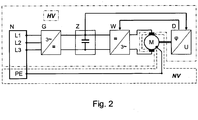
- a drive which comprises an converter-fed electric motor M, a rotation angle sensor D being provided on the rotor of the motor M.
- a rectifier G in particular a three-phase rectifier, is supplied from the AC network, i.e. by means of the mains supply N, the output-side unipolar voltage of which is smoothed by means of an intermediate circuit capacitor Z, to which the intermediate circuit voltage U_z is applied, which is a high voltage of up to 800 volts, for example.
- the rotation angle sensor D is located in the low-voltage range of the drive and is connected to ground potential.
- the power supply V for the electronic circuit arranged in the rotation angle sensor D separates the signal electronics and the rotation angle sensor D together with its electronic circuit from the high-voltage voltage.
- the rotation angle sensor is therefore preferably supplied from the secondary winding of a transformer, the primary winding of which is galvanically connected to the intermediate circuit, in particular to one of the intermediate circuit potentials.
- the signal transmission from the rotation angle sensor D to the signal electronics takes place without electrical isolation.
- the signal transmission of the control signals for the switches of the inverter are carried by the signal electronics to the switches of the inverter via the signal level converter P with electrical isolation.
- the inverter W feeding the motor is supplied from the intermediate circuit. It is controlled by the signal electronics with pulse-width-modulated control signals intended for its semiconductor switches in such a way that a three-phase voltage system is made available to the motor.
- the signal electronics comprise a controller, to which the detected rotation angle values and a detected motor current are fed.
- the controller On the output side, the controller provides values for output voltage, so that the pulse-width-modulated control signals can be generated accordingly, in particular taking into account the current intermediate circuit voltage.
- this insulation is also to be provided in the rotation angle sensor D.
- the signal electronics of the converter is therefore galvanically connected to a connection of the intermediate circuit capacitor, that is to say it is connected to the upper or lower intermediate circuit potential.
- the senor in particular its electronic circuit for generating the encoder signal and the associated signal conditioning, is also galvanically connected to an intermediate circuit potential, that is to say to a connection of the intermediate circuit capacitor. It is therefore at a high voltage potential compared to the PE or neutral conductor potential.
- an intermediate circuit potential that is to say to a connection of the intermediate circuit capacitor.
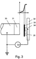
- FIG. 3 shows a schematic section for this.
- a shaft 30 of the motor in particular a metallic rotor shaft, is connected to ground via its bearing and has a measuring scale 31 at its axial end region.
- This measuring scale is preferably designed as a permanent magnet magnetized in the radial direction.
- a circuit board 32 on which sensors (34, 35) are provided, is arranged stationary opposite, in particular on the flange part or housing part of the motor.
- at least one sensor 34 in particular Wiegand sensor, and on the other hand at least one sensor 35, in particular Hall sensor, are provided.
- a cross-Hall sensor arranged centrally to the axis of the shaft is preferably used to detect the angular position.
- One or more pulse wire sensors that is to say Wiegand sensors, can be used to record the number of revolutions, so that even counting electronics can be supplied from the energy quantities of the pulses of the pulse wire sensors.
- An insulating means 33 is arranged between the printed circuit board 32 together with the components mounted on it and the shaft 30 together with the material measure 31, so that there is no electrical breakdown even at a short distance.
- the distance is so small that an electrical breakdown occurs when the insulating means 33 is omitted, since the potential difference between the high-voltage region and the low-voltage region is correspondingly large.
- the schematic course of the air gap potential is also indicated and shows the greater insulating strength of the insulating means 33 compared to the air
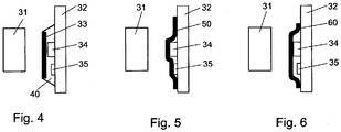
- the insulating medium is designed as a plate and is provided on an adhesive bed.
- the adhesive 40 is arranged between the circuit board 32 and the insulating means 33.
- the adhesive also acts as a potting compound, so that increased strength can be achieved for the entire arrangement or for the components, in particular sensors (34, 35), which are fitted on the printed circuit board.
- the insulating means 33 is designed as a rigid plate.
- FIG 5 Another embodiment is shown, in which, in contrast to Figure 4 the insulating means is designed as a flexible insulating plate 50, which lies on the surface of the adhesive 40 and partially follows it.
- the insulating means is designed as a preformed film, which in turn is glued to the printed circuit board 32 or is positively connected to the latter. When using adhesive 40, this is in turn arranged between the circuit board 32 and the preformed film.
- the insulating means is again in the form of a plate, in particular as a rigid plate, but potting compound 70 is provided on the circuit board in such a way that the insulating agent 33 is located within the potting compound, that is to say is potted.
- potting compound 70 is provided on the circuit board in such a way that the insulating agent 33 is located within the potting compound, that is to say is potted.
- Figure 8 is different from Figure 7 the insulating means is arranged on the surface of the potting compound 70, so that the insulating means is only partially potted, in particular on its side facing the printed circuit board 32.
- the plated-through holes used between the metallic layers 90 of the multilayer printed circuit board 32 are not contacted through the entire printed circuit board 32, that is to say they are only implemented as blind via 91 and thus only mediate a respective electrical contact between the regions to be electrically connected.
- the base material of the printed circuit board is thus used as an insulating means between the material measure 31 and electronic conductor tracks and components of the electronic circuit of the printed circuit board 32.
- the printed circuit board 32 faces the material measure Side metallic areas, especially where the areas form a regular grid.
- the printed circuit board 32 may be formed in one layer instead of in multiple layers.
- an insulating means is placed as a cap around the rotor shaft end with the measuring standard.
Description
Die Erfindung betrifft einen Antrieb.The invention relates to a drive.
Es ist möglich, eine galvanische Trennung zwischen der Sensorelektronik eines Winkelsensors eines elektrischen Elektromotors und der Signalelektronik des den Elektromotor speisenden Umrichters vorzusehen.It is possible to provide a galvanic separation between the sensor electronics of an angle sensor of an electric electric motor and the signal electronics of the converter feeding the electric motor.
Aus der
Aus der
Aus der
Aus der
Aus der
Der Erfindung liegt daher die Aufgabe zugrunde, einen Antrieb weiterzubilden, wobei eine möglichst kompakte und kostengünstige Anordnung erreicht werden soll.The invention is therefore based on the object of developing a drive, wherein the most compact and inexpensive arrangement possible.
Erfindungsgemäß wird die Aufgabe bei dem Antrieb nach den in Anspruch 1 angegebenen Merkmalen gelöst.According to the invention the object is achieved in the drive according to the features specified in claim 1.
Wichtige Merkmale der Erfindung bei dem Antrieb sind, dass er einen umrichtergespeisten Elektromotor umfasst, an dem ein Sensor zur Erfassung der Winkellage einer Welle, insbesondere einer Rotorwelle, des Elektromotors angeordnet ist,
wobei der Umrichter Signalelektronik, insbesondere umfassend einen Regler, und Leistungselektronik, insbesondere umfassend einen den Motor speisenden Wechselrichter, aufweist,
dadurch wobei die Sensorsignale der Signalelektronik zugeleitet werden, insbesondere direkt, also ohne galvanische Trennung.Important features of the invention in the drive are that it comprises an converter-fed electric motor on which a sensor for detecting the angular position of a shaft, in particular a rotor shaft, of the electric motor is arranged,
the converter having signal electronics, in particular comprising a controller, and power electronics, in particular comprising an inverter which feeds the motor,
thereby the sensor signals are fed to the signal electronics, in particular directly, that is to say without galvanic isolation.
Von Vorteil ist dabei, dass Bauteile zur galvanischen Trennung verzichtbar sind und somit eine möglichst kompakte und kostengünstige Bauart erreicht ist.The advantage here is that components for electrical isolation can be dispensed with, thus achieving the most compact and inexpensive design possible.
Bei einer vorteilhaften Ausgestaltung ist der Sensor mit der Signalelektronik galvanisch verbunden. Von Vorteil ist dabei, dass die Signale direkt auf gleichem Potential übermittelbar sind. Hierbei umfasst der Sensor eine Sensorelektronik, also eine mit elektronischen Bauteilen bestückte Leiterplatte, die Signale der von der Sensorelektronik umfassten Hall-Sensoren und Wigand-Sensoren verarbeitet.In an advantageous embodiment, the sensor is galvanically connected to the signal electronics. The advantage here is that the signals can be transmitted directly at the same potential. Here, the sensor comprises sensor electronics, that is to say a printed circuit board equipped with electronic components, which processes signals from the Hall sensors and Wigand sensors comprised by the sensor electronics.
Bei einer vorteilhaften Ausgestaltung ist an der Welle eine Maßverkörperung angeordnet, insbesondere an einem axialen Endbereich der Welle eine Maßverkörperung angeordnet. Von Vorteil ist dabei, dass ein Winkelerfassungssystem in den Elektromotor integriert ausführbar ist. Denn die Welle ist vorzugsweise Rotorwelle des Elektromotors und die Maßverkörperung ist somit im Inneren des Elektromotors angeordnet.In an advantageous embodiment, a material measure is arranged on the shaft, in particular a material measure is arranged on an axial end region of the shaft. The advantage here is that an angle detection system can be integrated into the electric motor. This is because the shaft is preferably the rotor shaft of the electric motor and the material measure is thus arranged in the interior of the electric motor.
Bei einer vorteilhaften Ausgestaltung steht der Sensor in Wirkverbindung mit der Maßverkörperung, insbesondere detektiert die Maßverkörperung, insbesondere zur Erfassung der Winkellage. Von Vorteil ist dabei, dass ein besonders einfach aufgebauter Sensor verwendbar ist, der keine eigenen Lager oder dergleichen benötigt. Somit sind auch von zusätzlichen Lagern verursachte Verluste vermeidbar.In an advantageous embodiment, the sensor is in operative connection with the material measure, in particular detects the material measure, in particular for detecting the angular position. The advantage here is that a particularly simple sensor can be used that does not require its own bearings or the like. Losses caused by additional bearings can thus be avoided.
Bei einer vorteilhaften Ausgestaltung ist ein Isoliermittel, insbesondere zur elektrischen Isolierung, zwischen der Maßverkörperung und dem Sensor angeordnet. Von Vorteil ist dabei, dass eine kompakte Anordnung erreichbar ist. Denn die magnetischen Felder durchdringen das Isoliermittel im Wesentlichen ungestört, wobei die elektrische Isolierung aber verbessert ist.In an advantageous embodiment, an insulating means, in particular for electrical insulation, is arranged between the material measure and the sensor. The advantage here is that a compact arrangement can be achieved. The magnetic fields penetrate the insulating material essentially undisturbed, but the electrical insulation is improved.
Bei einer vorteilhaften Ausgestaltung ist der Abstand zwischen Maßverkörperung und Sensor derart klein und die Isolierfestigkeit und/oder Durchschlagfestigkeit des Isoliermittels derart hoch, dass bei Entfernen des elektrischen Isoliermittels ein elektrischer Durchschlag stattfindet oder zumindest sehr wahrscheinlich ist, insbesondere zumindest bei ungünstigen Witterungsbedingungen oder Umgebungsbedingungen. Von Vorteil ist dabei, dass eine kompaktere Anordnung als bei bloßer Verwendung von Luft ausführbar ist. Insbesondere der Abstand zwischen Maßverkörperung und Leiterplatte mit Bauteilen, wie Hall-Sensor und/oder Wiegandsensor, ist gering haltbar.In an advantageous embodiment, the distance between the material measure and the sensor is so small and the insulation strength and / or dielectric strength of the insulation means is so high that when the electrical insulation means is removed, an electrical breakdown takes place or is at least very likely, in particular at least in unfavorable weather conditions or ambient conditions. The advantage here is that a more compact arrangement than with mere use of air can be carried out. In particular, the distance between the material measure and the printed circuit board with components, such as a Hall sensor and / or Wiegand sensor, can be kept short.
Bei einer vorteilhaften Ausgestaltung ist das Isoliermittel auf oder in Vergussmasse und/oder auf oder in Klebstoff angeordnet, wobei die Vergussmasse beziehungsweise der Klebstoff auch verbunden ist mit einer Leiterplatte des Sensors und/oder mit auf der Leiterplatte des Sensors bestückten Bauteilen. Von Vorteil ist dabei, dass ein stoffschlüssiges Halten des Isoliermittels bewirkbar ist und somit ein sicheres Halten gewährleistet ist. Außerdem ist die Vergussmasse und/oder der Klebstoff selbst aus isolierfestem Material ausführbar, so dass eine hohe Isolierfestigkeit erreichbar ist.In an advantageous embodiment, the insulating means is arranged on or in potting compound and / or on or in adhesive, the potting compound or adhesive also being connected to a circuit board of the sensor and / or to components fitted on the circuit board of the sensor. The advantage here is that a cohesive holding of the insulating means can be effected and thus a secure holding is ensured. In addition, the potting compound and / or the adhesive itself can be made from an insulating material, so that a high insulating strength can be achieved.
Bei einer vorteilhaften Ausgestaltung ist das Isoliermittel aus einem Material gefertigt, das eine höhere elektrische Isolierfestigkeit als Luft aufweist, insbesondere eine mindestens fünfmal höhere. Von Vorteil ist dabei, dass ein geringer Abstand zwischen Maßverkörperung und Leiterplatte erreichbar ist.In an advantageous embodiment, the insulating means is made of a material that has a higher electrical insulating strength than air, in particular at least five times higher. The advantage here is that a small distance between the material measure and the printed circuit board can be achieved.
Bei einer vorteilhaften Ausgestaltung ist das Isoliermittel als starre Platte ausgeführt. Von Vorteil ist dabei, dass eine einfache Montage mit Klebstoff oder Vergussmasse ausführbar ist.In an advantageous embodiment, the insulating means is designed as a rigid plate. The advantage here is that simple assembly with adhesive or potting compound can be carried out.
Bei einer vorteilhaften Ausgestaltung ist das Isoliermittel als flexible Folie, insbesondere selbstklebende Folie, ausgeführt und deckt die mit Bauteilen bestückte Leiterplatte an ihrer der Maßverkörperung zugewandten Seite zumindest teilweise ab. Von Vorteil ist dabei, dass die Folie ihre Form der Oberfläche der mit Bauteilen bestückten Leiterplatte anpasst.In an advantageous embodiment, the insulating means is designed as a flexible film, in particular a self-adhesive film, and at least partially covers the printed circuit board equipped with components on its side facing the measuring standard. The advantage here is that the film adapts its shape to the surface of the printed circuit board equipped with components.
Bei einer vorteilhaften Ausgestaltung ist das Isoliermittel als vorgeformte Folie, insbesondere selbstklebende Folie, ausgeführt und deckt die mit Bauteilen bestückte Leiterplatte an ihrer der Maßverkörperung zugewandten Seite zumindest teilweise ab. Von Vorteil ist dabei, dass eine einfache schnelle Positionierung bei der Montage erreichbar ist.In an advantageous embodiment, the insulating means is designed as a preformed film, in particular a self-adhesive film, and at least partially covers the printed circuit board equipped with components on its side facing the material measure. Is an advantage while ensuring that simple, quick positioning can be achieved during assembly.
Bei einer vorteilhaften Ausgestaltung ist das Isoliermittel zwischen Maßverkörperung und zumindest einem Teilbereich des Klebstoffes beziehungsweise der Vergussmasse angeordnet. Von Vorteil ist dabei, dass ein Vergießen des Isoliermittels oder ein Anordnen an der Oberfläche des Klebstoffes oder der Vergussmasse ermöglicht ist.In an advantageous embodiment, the insulating means is arranged between the material measure and at least a partial area of the adhesive or the potting compound. The advantage here is that a potting of the insulating agent or an arrangement on the surface of the adhesive or the potting compound is made possible.
Bei einer vorteilhaften Ausgestaltung ist die Maßverkörperung ein Dauermagnet, insbesondere ein in radialer Richtung magnetisierter Dauermagnet. Von Vorteil ist dabei, dass eine einfache Montage ermöglicht ist.In an advantageous embodiment, the material measure is a permanent magnet, in particular a permanent magnet magnetized in the radial direction. The advantage here is that simple assembly is possible.
Bei einer vorteilhaften Ausgestaltung umfasst der Sensor zumindest einen Hall-Sensor und/oder einen Wiegand-Sensor, insbesondere wobei der Sensor auch einen Auswerteschaltung zur Erzeugung der Sensorsignale aus den Ausgangssignalen des Wiegand-Sensors und/oder Hall-Sensors umfasst. Von Vorteil ist dabei, dass eine Erfassung der Winkellage einerseits und eine Erfassung der Anzahl der zurückgelegten Gesamtumdrehungen ausführbar ist.In an advantageous embodiment, the sensor comprises at least one Hall sensor and / or a Wiegand sensor, in particular wherein the sensor also comprises an evaluation circuit for generating the sensor signals from the output signals of the Wiegand sensor and / or Hall sensor. The advantage here is that the angular position on the one hand and the number of total revolutions covered can be carried out.
Bei einer vorteilhaften Ausgestaltung ist ein Gleichrichter des Umrichters aus einer Netz-Wechselspannung versorgt und die Signalelektronik ist galvanisch verbunden mit einem Ausgang des Gleichrichters und/oder die Signalelektronik ist galvanisch verbunden mit einem Potential einen Wechselrichter des Umrichters versorgenden unipolaren Spannung und/oder Gleichspannung, insbesondere Zwischenkreisspannung. Von Vorteil ist dabei, dass keine Bauteile zur galvanischen Trennung erforderlich sind.In an advantageous embodiment, a rectifier of the converter is supplied from a mains AC voltage and the signal electronics is electrically connected to an output of the rectifier and / or the signal electronics is electrically connected to a potential supplying an inverter of the converter with unipolar voltage and / or DC voltage, in particular DC link voltage. The advantage here is that no components are required for electrical isolation.
Bei einer vorteilhaften Ausgestaltung erzeugt die Signalelektronik pulsweitenmodulierte Ansteuersignale für Halbleiterschalter des Wechselrichters, wobei die Sensorsignale berücksichtigt werden und/oder der Sensorsignalverlauf berücksichtigt wird. Von Vorteil ist dabei, dass eine besonders zeitaktuelle und genaue Erzeugung der pulsweitemodulierten Ansteuersignale ausführbar ist, da die galvanische Trennung und somit eine damit verbundene Zeitverzögerung entfällt.In an advantageous embodiment, the signal electronics generate pulse-width-modulated control signals for semiconductor switches of the inverter, the sensor signals being taken into account and / or the sensor signal curve being taken into account. The advantage here is that a particularly timely and precise generation of the pulse-width-modulated control signals can be carried out, since the galvanic isolation and thus the associated time delay are eliminated.
Weitere Vorteile ergeben sich aus den Unteransprüchen. Die Erfindung ist nicht auf die Merkmalskombination der Ansprüche beschränkt. Für den Fachmann ergeben sich weitere sinnvolle Kombinationsmöglichkeiten von Ansprüchen und/oder einzelnen Anspruchsmerkmalen und/oder Merkmalen der Beschreibung und/oder der Figuren, insbesondere aus der Aufgabenstellung und/oder der sich durch Vergleich mit dem Stand der Technik stellenden Aufgabe.Further advantages result from the subclaims. The invention is not limited to the combination of features of the claims. For the person skilled in the art there are further useful possible combinations of claims and / or individual claim features and / or features of the description and / or the figures, in particular from the task and / or the task arising from comparison with the prior art.
Die Erfindung wird nun anhand von Abbildungen näher erläutert:
- In der
Figur 1 ist ein Antrieb schematisch skizziert.
- In the
Figure 1 a drive is schematically outlined.
In der
In der
In den
In der
Der Drehwinkelsensor D befindet sich im Niedervoltbereich des Antriebs und ist auf Massepotential gelegt. Die Stromversorgung V für die im Drehwinkelsensor D angeordnete elektronische Schaltung trennt die Signalelektronik und den Drehwinkelsensor D samt seiner elektronischen Schaltung von der Hochvoltspannung. Vorzugsweise wird also der Drehwinkelsensor aus der Sekundärwicklung eines Transformators versorgt, dessen Primärwicklung galvanisch mit dem Zwischenkreis verbunden ist, insbesondere mit einem der Zwischenkreispotentiale. Die Signalübertragung vom Drehwinkelsensor D zur Signalelektronik erfolgt ohne galvanische Trennung. Die Signalübertragung der Ansteuersignale für die Schalter des Wechselrichters werden von der Signalelektronik zu den Schaltern des Wechselrichters über den Signalpegelwandler P mit galvanischer Trennung geführt.The rotation angle sensor D is located in the low-voltage range of the drive and is connected to ground potential. The power supply V for the electronic circuit arranged in the rotation angle sensor D separates the signal electronics and the rotation angle sensor D together with its electronic circuit from the high-voltage voltage. The rotation angle sensor is therefore preferably supplied from the secondary winding of a transformer, the primary winding of which is galvanically connected to the intermediate circuit, in particular to one of the intermediate circuit potentials. The signal transmission from the rotation angle sensor D to the signal electronics takes place without electrical isolation. The signal transmission of the control signals for the switches of the inverter are carried by the signal electronics to the switches of the inverter via the signal level converter P with electrical isolation.
Der den Motor speisende Wechselrichter W wird aus dem Zwischenkreis versorgt. Er wird derart mit für seine Halbleiterschalter bestimmten pulsweitenmodulierten Ansteuersignalen von der Signalelektronik angesteuert, dass dem Motor ein Drehspannungssystem zur Verfügung gestellt wird.The inverter W feeding the motor is supplied from the intermediate circuit. It is controlled by the signal electronics with pulse-width-modulated control signals intended for its semiconductor switches in such a way that a three-phase voltage system is made available to the motor.
Die Signalelektronik umfasst einen Regler, dem die erfassten Drehwinkelwerte sowie ein erfasster Motorstrom zugeführt werden. Ausgangsseitig stellt der Regler Werte für Ausgangsspannung bereit, so dass die pulsweitenmodulierten Ansteuersignale entsprechend erzeugbar sind, insbesondere unter Berücksichtigung der aktuell vorhandenen Zwischenkreisspannung.The signal electronics comprise a controller, to which the detected rotation angle values and a detected motor current are fed. On the output side, the controller provides values for output voltage, so that the pulse-width-modulated control signals can be generated accordingly, in particular taking into account the current intermediate circuit voltage.
In der
Diese Isolierung ist erfindungsgemäß auch im Drehwinkelsensor D vorzusehen.According to the invention, this insulation is also to be provided in the rotation angle sensor D.
Die Signalelektronik des Umrichters ist also galvanisch mit einem Anschluss des Zwischenkreiskondensators verbunden, ist also an das obere oder untere Zwischenkreispotential angebunden.The signal electronics of the converter is therefore galvanically connected to a connection of the intermediate circuit capacitor, that is to say it is connected to the upper or lower intermediate circuit potential.
Ebenso ist auch der Sensor, insbesondere seine elektronische Schaltung zur Erzeugung der Gebersignal und die zugehörige Signalaufbereitung galvanisch mit einem Zwischenkreispotential verbunden, also mit einem Anschluss des Zwischenkreiskondensators. Sie liegt somit auf einem Hochvoltpotential gegenüber dem PE oder Nullleiterpotential. Zwischen der elektronischen Schaltung des Sensors, also Drehwinkelgebers, und der Signalelektronik des Umrichters besteht keine galvanische Trennung sondern es ist sogar eine galvanische Verbindung vorhanden, insbesondere eines elektrischen Anschlusses des Sensors mit einem metallischen Beriech der Leiterplatte der Signalelektronik des Umrichters.Likewise, the sensor, in particular its electronic circuit for generating the encoder signal and the associated signal conditioning, is also galvanically connected to an intermediate circuit potential, that is to say to a connection of the intermediate circuit capacitor. It is therefore at a high voltage potential compared to the PE or neutral conductor potential. There is no galvanic isolation between the electronic circuit of the sensor, i.e. the angle encoder, and the signal electronics of the converter, but there is even a galvanic connection, in particular an electrical connection of the sensor with a metallic area of the circuit board of the signal electronics of the converter.
Somit ist eine Erfassung der Winkellage der Welle 30 und der Anzahl der Gesamtumdrehungen ausführbar. Vorzugsweise wird zur Erfassung der Winkellage ein zur Achse der Welle mittig angeordneter Kreuz-Hall-Sensor verwendet. Zur Erfassung der Anzahl der Umdrehungen sind ein oder mehrere Impulsdrahtsensoren, also Wiegand-Sensoren, verwendbar, so dass sogar eine Zählelektronik versorgbar ist aus den Energiemengen der Pulse der Impulsdrahtsensoren.The angular position of the
Zwischen der Leiterplatte 32 samt der auf ihr bestückten Bauteile und der Welle 30 samt der Maßverkörperung 31 ist ein Isoliermittel 33 angeordnet, so dass auch bei geringem Abstand kein elektrischer Durchschlag erfolgt.An insulating means 33 is arranged between the printed
Der Abstand ist dabei derart klein, dass bei Weglassen des Isoliermittels 33 ein elektrischer Durchschlag erfolgt, da die Potentialdifferenz zwischen dem Hochspannungsbereich und dem Niederspannungsbereich entsprechend groß ist.The distance is so small that an electrical breakdown occurs when the insulating
Dies ist in der Figur mit der symbolischen Spannungsquelle U_z angedeutet, die Zwischenkreisspannung aufweist.This is indicated in the figure by the symbolic voltage source U_z, which has an intermediate circuit voltage.
Der schematische Verlauf des Luftspaltpotentials ist ebenfalls angedeutet und zeigt die im Vergleich zur Luft größere Isolierfestigkeit des Isoliermittels 33The schematic course of the air gap potential is also indicated and shows the greater insulating strength of the insulating means 33 compared to the air
In
In
In
In
In
In
Die verwendeten Durchkontaktierungen zwischen den metallischen Lagen 90 der Multilayer-Leiterplatte 32 sind nicht durch die gesamte Leiterplatte 32 hindurch kontaktiert, also nur als blind via 91 ausgeführt und vermitteln somit nur zwischen den elektrisch zu verbindenden Bereichen einen jeweiligen elektrischen Kontakt.The plated-through holes used between the
Somit wird das Grundmaterial der Leiterplatte als Isoliermittel zwischen Maßverkörperung 31 und elektronischen Leiterbahnen sowie Bauteilen der elektronischen Schaltung der Leiterplatte 32 verwendet.The base material of the printed circuit board is thus used as an insulating means between the
Zur mechanischen Stabilisierung weist die Leiterplatte 32 auf der der Maßverkörperung zugewandten Seite metallische Bereiche auf, insbesondere wobei die Bereiche ein regelmäßiges Gitter bilden.For mechanical stabilization, the printed
Die Leiterplatte 32 darf in weiteren Ausführungsbeispielen einlagig statt mehrlagig ausgebildet sein.In further exemplary embodiments, the printed
Alternativ oder zusätzlich ist ein Isoliermittel als Kappe um das Rotorwellenende mit der Maßverkörperung aufgesetzt.Alternatively or additionally, an insulating means is placed as a cap around the rotor shaft end with the measuring standard.
- N NetzversorgungN mains supply
- Z ZwischenkreiskondensatorZ DC link capacitor
- M DrehstrommotorM three-phase motor
- V StromversorgungsmodulV power supply module
- HV HochspannungsteilHV high voltage part
- G Gleichrichter, insbesondere DreiphasengleichrichterG rectifiers, especially three-phase rectifiers
- W Wechselrichter, insbesondere DreiphasenwechselrichterW inverters, especially three-phase inverters
- D DrehwinkelsensorD angle of rotation sensor
- P Signalpegelwandler mit galvanischer TrennungP signal level converter with galvanic isolation
- NV NiederspannungsteilNV low voltage part
- U_z ZwischenkreisspannungU_z DC link voltage
- 30 Welle30 wave
- 31 Maßverkörperung, beispielsweise Dauermagnet31 material measure, for example permanent magnet
- 32 Leiterplatte32 circuit board
- 33 Isoliermittel33 insulation
- 34 Sensor, insbesondere Wiegand-Sensor34 sensor, in particular Wiegand sensor
- 35 Sensor, insbesondere Hall-Sensor35 sensor, in particular Hall sensor
- 40 Kleber40 glue
- 50 flexibles Isolierplättchen50 flexible insulating plates
- 60 flexible Folie, insbesondere vorgeformte Folie60 flexible film, especially preformed film
- 70 Vergussmasse70 potting compound
- 90 metallische Bereiche, Lagen90 metallic areas, layers
- 91 blind via, nicht durch die gesamte Leiterplatte (32) hindurchgehende Durchkontaktierung91 blind via, via that does not go through the entire printed circuit board (32)
Claims (13)
- Drive, comprising a converter-fed electric motor on which is arranged a sensor (35), in particular an angle-of-rotation transducer, for detecting the angular position of a shaft (30), in particular of a rotor shaft, of the electric motor,
wherein the converter has signal electronics, in particular comprising a controller, and power electronics, comprising an inverter feeding the motor,
wherein the inverter is fed from an intermediate circuit voltage, in particular which is more than 50 volts or more than 100 volts,
wherein the intermediate circuit voltage feeds an intermediate circuit capacitor or a corresponding intermediate circuit capacitance, in particular is smoothed by the capacitor or capacitance,
wherein the sensor (35) comprises an electronic circuit for generating transducer signals with associated signal processing,
characterised in that
the electronic circuit of the sensor (35) is electrically connected to an intermediate circuit potential of the intermediate circuit voltage, in particular therefore to one of the terminals of the intermediate circuit capacitor or a corresponding intermediate circuit capacitance,
wherein a material measure (31) is arranged at an axial end region of the shaft (30),
wherein a printed circuit board (32) comprised by the electronic circuit of the sensor (35) is used as insulating means (33) for electrical insulation between the material measure (31) and the sensor (35),
wherein the components (34, 35) of the electronic circuit are arranged on the side of the printed circuit board (32) facing away from the material measure (31). - Drive according to Claim 1,
characterised in that
the sensor (35) is electrically connected to the signal electronics
and/or in that
the sensor signals are supplied to the signal electronics, i.e. directly, i.e. without electrical isolation. - Drive according to at least one of the preceding claims,
characterised in that
the sensor (35) is in operative connection with the material measure (31), in particular detects the material measure (31), in particular for detecting the angular position. - Drive according to at least one of the preceding claims,
characterised in that
the dielectric strength of the material of the insulating means (33) is greater than 3kV/mm and/or than the dielectric strength of air, in particular of dry ambient air at -10°C and a pressure of 1 bar. - Drive according to at least one of the preceding claims,
characterised in that
the printed circuit board (32) has no throughplatings passing through the entire printed circuit board (32), in particular wherein, the printed circuit board (32) therefore has only blind vias (91) as throughplatings.
and/or in that the direction of normal to the printed circuit board (32) is oriented in the shaft axis direction,
and/or in that the printed circuit board (32) is formed of one layer or more than one layer, wherein the layers are provided in an electrically insulating base material. - Drive according to at least one of the preceding claims,
characterised in that
the printed circuit board (32) has metallic regions (90) on the side facing the material measure (31), in particular wherein the regions (90) form a regular grid. - Drive according to at least one of the preceding claims,
characterised in that
an insulating means (33), in particular for electrical insulation, is rotationally fixedly connected to the material measure (31), in particular wherein the insulating means (33) is connected to the material measure (31) in a material-locking, force-locking and/or form-locking manner,
in particular wherein the insulating means (33) is of cap-shaped form and/or is connected in a clipped-on manner to the material measure (31)
and/or wherein the insulating means (33) is axially extended such that it at least partially axially covers the axial region covered by the material measure (31),
in particular wherein the shaft axis defines the axial direction. - Drive according to at least one of the preceding claims,
characterised in that
the distance between the material measure (31) and the sensor (35) is so small and the insulating strength and/or dielectric strength of the insulating means (33) is so high that an electric breakdown takes place, or at least is very likely, when the electrical insulating means (33) is removed. - Drive according to at least one of the preceding claims,
characterised in that
an additional insulating means is arranged on or in sealing compound (70) and/or on or in adhesive, wherein the sealing compound (70) or the adhesive is also connected to a printed circuit board (32) of the sensor (35) and/or to components fitted on the printed circuit board (32) of the sensor (35),
in particular wherein the insulating means (33) is made of a material which has a higher electrical insulating strength than air, in particular at least five times higher,
and/or in that
an additional insulating means is designed as a rigid plate
and/or in that
an additional insulating means is designed as a flexible film (60), in particular a self-adhesive film (60), and at least partially covers the printed circuit board (32), fitted with components, at its side facing the material measure (31),
and/or in that
an additional insulating means is designed as a preformed film (60), in particular a self-adhesive film (60), and at least partially covers the printed circuit board (32), fitted with components, at its side facing the material measure (31),
and/or in that
an additional insulating means is arranged between the material measure (31) and at least one partial region of the adhesive or of the sealing compound (70). - Drive according to at least one of the preceding claims,
characterised in that
the material measure (31) is a permanent magnet, in particular a permanent magnet magnetised in the radial direction. - Drive according to at least one of the preceding claims,
characterised in that
the sensor (35) comprises at least one Hall sensor (35) and/or a Wiegand sensor, in particular wherein the sensor (35) also comprises an evaluating circuit for generating the sensor signals from the output signals of the Wiegand sensor and/or Hall sensor (35). - Drive according to at least one of the preceding claims,
characterised in that
a rectifier of the converter is supplied from a mains alternating voltage and the signal electronics are electrically connected to an output of the rectifier and/or the signal electronics are electrically connected to a potential supplying an inverter of the converter unipolar voltage and/or direct voltage, in particular intermediate circuit voltage. - Drive according to at least one of the preceding claims,
characterised in that
the signal electronics generate pulse-width-modulated control signals for semiconductor switches of the inverter, wherein the sensor signals are taken into account and/or the sensor signal profile is considered.
Applications Claiming Priority (2)
| Application Number | Priority Date | Filing Date | Title |
|---|---|---|---|
| DE102010049681A DE102010049681A1 (en) | 2010-10-28 | 2010-10-28 | drive |
| PCT/EP2011/005338 WO2012055521A2 (en) | 2010-10-28 | 2011-10-24 | Drive |
Publications (3)
| Publication Number | Publication Date |
|---|---|
| EP2633618A2 EP2633618A2 (en) | 2013-09-04 |
| EP2633618B1 EP2633618B1 (en) | 2017-09-06 |
| EP2633618B2 true EP2633618B2 (en) | 2020-05-27 |
Family
ID=45047704
Family Applications (1)
| Application Number | Title | Priority Date | Filing Date |
|---|---|---|---|
| EP11788362.9A Active EP2633618B2 (en) | 2010-10-28 | 2011-10-24 | Drive |
Country Status (3)
| Country | Link |
|---|---|
| EP (1) | EP2633618B2 (en) |
| DE (1) | DE102010049681A1 (en) |
| WO (1) | WO2012055521A2 (en) |
Families Citing this family (2)
| Publication number | Priority date | Publication date | Assignee | Title |
|---|---|---|---|---|
| JP6261776B2 (en) * | 2015-01-23 | 2018-01-17 | 三菱電機株式会社 | Electric drive |
| US20220200368A1 (en) | 2020-12-23 | 2022-06-23 | Black & Decker Inc. | Brushless dc motor with improved slot fill |
Citations (2)
| Publication number | Priority date | Publication date | Assignee | Title |
|---|---|---|---|---|
| EP1610095A1 (en) † | 2004-06-21 | 2005-12-28 | HERA Rotterdam B.V. | Rotation detector for determining the absolute angular position of a shaft |
| DE102008037737A1 (en) † | 2007-08-28 | 2009-03-05 | Sew-Eurodrive Gmbh & Co. Kg | Electric motor with angle sensor |
Family Cites Families (5)
| Publication number | Priority date | Publication date | Assignee | Title |
|---|---|---|---|---|
| US6296065B1 (en) * | 1998-12-30 | 2001-10-02 | Black & Decker Inc. | Dual-mode non-isolated corded system for transportable cordless power tools |
| GB9924299D0 (en) * | 1999-10-15 | 1999-12-15 | Siemens Ag | Apparatus and method for measuring current |
| DE10207400B4 (en) | 2001-02-24 | 2019-03-14 | Marquardt Gmbh | Device for adjusting the angle of rotation |
| US7202619B1 (en) * | 2005-02-24 | 2007-04-10 | Gary Randolph Fisher | Variable frequency drive for AC synchronous motors with application to pumps |
| DE102007036271A1 (en) * | 2007-07-31 | 2009-02-05 | Baumer Hübner GmbH | Encoder with monitoring of bearing wear and method |
-
2010
- 2010-10-28 DE DE102010049681A patent/DE102010049681A1/en active Pending
-
2011
- 2011-10-24 EP EP11788362.9A patent/EP2633618B2/en active Active
- 2011-10-24 WO PCT/EP2011/005338 patent/WO2012055521A2/en active Application Filing
Patent Citations (2)
| Publication number | Priority date | Publication date | Assignee | Title |
|---|---|---|---|---|
| EP1610095A1 (en) † | 2004-06-21 | 2005-12-28 | HERA Rotterdam B.V. | Rotation detector for determining the absolute angular position of a shaft |
| DE102008037737A1 (en) † | 2007-08-28 | 2009-03-05 | Sew-Eurodrive Gmbh & Co. Kg | Electric motor with angle sensor |
Also Published As
| Publication number | Publication date |
|---|---|
| EP2633618B1 (en) | 2017-09-06 |
| WO2012055521A3 (en) | 2013-05-10 |
| WO2012055521A2 (en) | 2012-05-03 |
| DE102010049681A1 (en) | 2012-05-03 |
| EP2633618A2 (en) | 2013-09-04 |
Similar Documents
| Publication | Publication Date | Title |
|---|---|---|
| EP1906153B1 (en) | Rotary encoder and method for its operation | |
| EP1422809B1 (en) | Electric motor for a pump drive | |
| EP1160960B1 (en) | Explosion proof motor assembly | |
| WO2010025806A1 (en) | Roller drive and system of roller drives | |
| WO2015067497A2 (en) | Electric machine | |
| EP2705413B1 (en) | Drive system and method for operating a drive system | |
| EP3078112B1 (en) | Actuator with position sensor | |
| EP2542865B1 (en) | Bearing current sensor with energy converter | |
| EP2633618B2 (en) | Drive | |
| EP2863184B1 (en) | Rotary encoder having a self-sufficient energy supply | |
| DE10362051B4 (en) | Electric motor and method of manufacture | |
| EP3452345B1 (en) | Actuator device for a vehicle, braking system | |
| EP3475771B1 (en) | Device for isolated fan control and fan system and control method | |
| EP1452739B1 (en) | Pump-controller interface | |
| EP2689530A2 (en) | Drive system and method for operating a drive system | |
| EP2551999A1 (en) | Electric machine with excitation without slip ring | |
| DE102020203272A1 (en) | engine | |
| DE102010049682A1 (en) | Drive, has sensor comprising electronic circuit galvanically connected with intermediate circuit potential of intermediate circuit voltage with connection of intermediate circuit condenser or intermediate circuit capacitor | |
| WO2020064274A1 (en) | Device and method for supplying energy to a sensor device in a rail vehicle | |
| DE102015201160B4 (en) | Brushless DC motor | |
| DE102021103062A1 (en) | stator | |
| EP3063505A1 (en) | Position sensor for detecting a position of an actuator | |
| EP3984118A1 (en) | Interference-suppressed linear drive | |
| DE202015106847U1 (en) | Fan with status signal generation and transmission of the status signal via a supply line | |
| DE10320613A1 (en) | Electrical machine with a sensor system |
Legal Events
| Date | Code | Title | Description |
|---|---|---|---|
| PUAI | Public reference made under article 153(3) epc to a published international application that has entered the european phase |
Free format text: ORIGINAL CODE: 0009012 |
|
| AK | Designated contracting states |
Kind code of ref document: A2 Designated state(s): AL AT BE BG CH CY CZ DE DK EE ES FI FR GB GR HR HU IE IS IT LI LT LU LV MC MK MT NL NO PL PT RO RS SE SI SK SM TR |
|
| AX | Request for extension of the european patent |
Extension state: BA ME |
|
| 17P | Request for examination filed |
Effective date: 20131111 |
|
| RBV | Designated contracting states (corrected) |
Designated state(s): AL AT BE BG CH CY CZ DE DK EE ES FI FR GB GR HR HU IE IS IT LI LT LU LV MC MK MT NL NO PL PT RO RS SE SI SK SM TR |
|
| DAX | Request for extension of the european patent (deleted) | ||
| GRAP | Despatch of communication of intention to grant a patent |
Free format text: ORIGINAL CODE: EPIDOSNIGR1 |
|
| INTG | Intention to grant announced |
Effective date: 20170425 |
|
| GRAS | Grant fee paid |
Free format text: ORIGINAL CODE: EPIDOSNIGR3 |
|
| GRAA | (expected) grant |
Free format text: ORIGINAL CODE: 0009210 |
|
| AK | Designated contracting states |
Kind code of ref document: B1 Designated state(s): AL AT BE BG CH CY CZ DE DK EE ES FI FR GB GR HR HU IE IS IT LI LT LU LV MC MK MT NL NO PL PT RO RS SE SI SK SM TR |
|
| REG | Reference to a national code |
Ref country code: GB Ref legal event code: FG4D Free format text: NOT ENGLISH |
|
| REG | Reference to a national code |
Ref country code: CH Ref legal event code: EP Ref country code: CH Ref legal event code: NV Representative=s name: HEPP WENGER RYFFEL AG, CH Ref country code: AT Ref legal event code: REF Ref document number: 926901 Country of ref document: AT Kind code of ref document: T Effective date: 20170915 |
|
| REG | Reference to a national code |
Ref country code: FR Ref legal event code: PLFP Year of fee payment: 7 |
|
| REG | Reference to a national code |
Ref country code: IE Ref legal event code: FG4D Free format text: LANGUAGE OF EP DOCUMENT: GERMAN |
|
| REG | Reference to a national code |
Ref country code: DE Ref legal event code: R096 Ref document number: 502011012971 Country of ref document: DE |
|
| REG | Reference to a national code |
Ref country code: NL Ref legal event code: MP Effective date: 20170906 |
|
| REG | Reference to a national code |
Ref country code: LT Ref legal event code: MG4D |
|
| PG25 | Lapsed in a contracting state [announced via postgrant information from national office to epo] |
Ref country code: HR Free format text: LAPSE BECAUSE OF FAILURE TO SUBMIT A TRANSLATION OF THE DESCRIPTION OR TO PAY THE FEE WITHIN THE PRESCRIBED TIME-LIMIT Effective date: 20170906 Ref country code: FI Free format text: LAPSE BECAUSE OF FAILURE TO SUBMIT A TRANSLATION OF THE DESCRIPTION OR TO PAY THE FEE WITHIN THE PRESCRIBED TIME-LIMIT Effective date: 20170906 Ref country code: LT Free format text: LAPSE BECAUSE OF FAILURE TO SUBMIT A TRANSLATION OF THE DESCRIPTION OR TO PAY THE FEE WITHIN THE PRESCRIBED TIME-LIMIT Effective date: 20170906 Ref country code: NO Free format text: LAPSE BECAUSE OF FAILURE TO SUBMIT A TRANSLATION OF THE DESCRIPTION OR TO PAY THE FEE WITHIN THE PRESCRIBED TIME-LIMIT Effective date: 20171206 Ref country code: SE Free format text: LAPSE BECAUSE OF FAILURE TO SUBMIT A TRANSLATION OF THE DESCRIPTION OR TO PAY THE FEE WITHIN THE PRESCRIBED TIME-LIMIT Effective date: 20170906 |
|
| PG25 | Lapsed in a contracting state [announced via postgrant information from national office to epo] |
Ref country code: BG Free format text: LAPSE BECAUSE OF FAILURE TO SUBMIT A TRANSLATION OF THE DESCRIPTION OR TO PAY THE FEE WITHIN THE PRESCRIBED TIME-LIMIT Effective date: 20171206 Ref country code: LV Free format text: LAPSE BECAUSE OF FAILURE TO SUBMIT A TRANSLATION OF THE DESCRIPTION OR TO PAY THE FEE WITHIN THE PRESCRIBED TIME-LIMIT Effective date: 20170906 Ref country code: ES Free format text: LAPSE BECAUSE OF FAILURE TO SUBMIT A TRANSLATION OF THE DESCRIPTION OR TO PAY THE FEE WITHIN THE PRESCRIBED TIME-LIMIT Effective date: 20170906 Ref country code: GR Free format text: LAPSE BECAUSE OF FAILURE TO SUBMIT A TRANSLATION OF THE DESCRIPTION OR TO PAY THE FEE WITHIN THE PRESCRIBED TIME-LIMIT Effective date: 20171207 Ref country code: RS Free format text: LAPSE BECAUSE OF FAILURE TO SUBMIT A TRANSLATION OF THE DESCRIPTION OR TO PAY THE FEE WITHIN THE PRESCRIBED TIME-LIMIT Effective date: 20170906 |
|
| PG25 | Lapsed in a contracting state [announced via postgrant information from national office to epo] |
Ref country code: NL Free format text: LAPSE BECAUSE OF FAILURE TO SUBMIT A TRANSLATION OF THE DESCRIPTION OR TO PAY THE FEE WITHIN THE PRESCRIBED TIME-LIMIT Effective date: 20170906 |
|
| PG25 | Lapsed in a contracting state [announced via postgrant information from national office to epo] |
Ref country code: RO Free format text: LAPSE BECAUSE OF FAILURE TO SUBMIT A TRANSLATION OF THE DESCRIPTION OR TO PAY THE FEE WITHIN THE PRESCRIBED TIME-LIMIT Effective date: 20170906 Ref country code: PL Free format text: LAPSE BECAUSE OF FAILURE TO SUBMIT A TRANSLATION OF THE DESCRIPTION OR TO PAY THE FEE WITHIN THE PRESCRIBED TIME-LIMIT Effective date: 20170906 Ref country code: CZ Free format text: LAPSE BECAUSE OF FAILURE TO SUBMIT A TRANSLATION OF THE DESCRIPTION OR TO PAY THE FEE WITHIN THE PRESCRIBED TIME-LIMIT Effective date: 20170906 |
|
| PG25 | Lapsed in a contracting state [announced via postgrant information from national office to epo] |
Ref country code: IS Free format text: LAPSE BECAUSE OF FAILURE TO SUBMIT A TRANSLATION OF THE DESCRIPTION OR TO PAY THE FEE WITHIN THE PRESCRIBED TIME-LIMIT Effective date: 20180106 Ref country code: SM Free format text: LAPSE BECAUSE OF FAILURE TO SUBMIT A TRANSLATION OF THE DESCRIPTION OR TO PAY THE FEE WITHIN THE PRESCRIBED TIME-LIMIT Effective date: 20170906 Ref country code: SK Free format text: LAPSE BECAUSE OF FAILURE TO SUBMIT A TRANSLATION OF THE DESCRIPTION OR TO PAY THE FEE WITHIN THE PRESCRIBED TIME-LIMIT Effective date: 20170906 Ref country code: IT Free format text: LAPSE BECAUSE OF FAILURE TO SUBMIT A TRANSLATION OF THE DESCRIPTION OR TO PAY THE FEE WITHIN THE PRESCRIBED TIME-LIMIT Effective date: 20170906 Ref country code: EE Free format text: LAPSE BECAUSE OF FAILURE TO SUBMIT A TRANSLATION OF THE DESCRIPTION OR TO PAY THE FEE WITHIN THE PRESCRIBED TIME-LIMIT Effective date: 20170906 |
|
| REG | Reference to a national code |
Ref country code: DE Ref legal event code: R026 Ref document number: 502011012971 Country of ref document: DE |
|
| PLBI | Opposition filed |
Free format text: ORIGINAL CODE: 0009260 |
|
| PLAX | Notice of opposition and request to file observation + time limit sent |
Free format text: ORIGINAL CODE: EPIDOSNOBS2 |
|
| PG25 | Lapsed in a contracting state [announced via postgrant information from national office to epo] |
Ref country code: MC Free format text: LAPSE BECAUSE OF FAILURE TO SUBMIT A TRANSLATION OF THE DESCRIPTION OR TO PAY THE FEE WITHIN THE PRESCRIBED TIME-LIMIT Effective date: 20170906 |
|
| 26 | Opposition filed |
Opponent name: LENZE DRIVES GMBH Effective date: 20180606 |
|
| REG | Reference to a national code |
Ref country code: IE Ref legal event code: MM4A |
|
| PG25 | Lapsed in a contracting state [announced via postgrant information from national office to epo] |
Ref country code: LU Free format text: LAPSE BECAUSE OF NON-PAYMENT OF DUE FEES Effective date: 20171024 Ref country code: DK Free format text: LAPSE BECAUSE OF FAILURE TO SUBMIT A TRANSLATION OF THE DESCRIPTION OR TO PAY THE FEE WITHIN THE PRESCRIBED TIME-LIMIT Effective date: 20170906 |
|
| REG | Reference to a national code |
Ref country code: BE Ref legal event code: MM Effective date: 20171031 |
|
| PLAS | Information related to reply of patent proprietor to notice(s) of opposition deleted |
Free format text: ORIGINAL CODE: EPIDOSDOBS3 |
|
| PLBB | Reply of patent proprietor to notice(s) of opposition received |
Free format text: ORIGINAL CODE: EPIDOSNOBS3 |
|
| PG25 | Lapsed in a contracting state [announced via postgrant information from national office to epo] |
Ref country code: SI Free format text: LAPSE BECAUSE OF FAILURE TO SUBMIT A TRANSLATION OF THE DESCRIPTION OR TO PAY THE FEE WITHIN THE PRESCRIBED TIME-LIMIT Effective date: 20170906 Ref country code: BE Free format text: LAPSE BECAUSE OF NON-PAYMENT OF DUE FEES Effective date: 20171031 |
|
| REG | Reference to a national code |
Ref country code: FR Ref legal event code: PLFP Year of fee payment: 8 |
|
| PG25 | Lapsed in a contracting state [announced via postgrant information from national office to epo] |
Ref country code: MT Free format text: LAPSE BECAUSE OF FAILURE TO SUBMIT A TRANSLATION OF THE DESCRIPTION OR TO PAY THE FEE WITHIN THE PRESCRIBED TIME-LIMIT Effective date: 20170906 |
|
| PG25 | Lapsed in a contracting state [announced via postgrant information from national office to epo] |
Ref country code: IE Free format text: LAPSE BECAUSE OF NON-PAYMENT OF DUE FEES Effective date: 20171024 |
|
| PG25 | Lapsed in a contracting state [announced via postgrant information from national office to epo] |
Ref country code: HU Free format text: LAPSE BECAUSE OF FAILURE TO SUBMIT A TRANSLATION OF THE DESCRIPTION OR TO PAY THE FEE WITHIN THE PRESCRIBED TIME-LIMIT; INVALID AB INITIO Effective date: 20111024 |
|
| PG25 | Lapsed in a contracting state [announced via postgrant information from national office to epo] |
Ref country code: CY Free format text: LAPSE BECAUSE OF NON-PAYMENT OF DUE FEES Effective date: 20170906 |
|
| PG25 | Lapsed in a contracting state [announced via postgrant information from national office to epo] |
Ref country code: MK Free format text: LAPSE BECAUSE OF FAILURE TO SUBMIT A TRANSLATION OF THE DESCRIPTION OR TO PAY THE FEE WITHIN THE PRESCRIBED TIME-LIMIT Effective date: 20170906 |
|
| PG25 | Lapsed in a contracting state [announced via postgrant information from national office to epo] |
Ref country code: TR Free format text: LAPSE BECAUSE OF FAILURE TO SUBMIT A TRANSLATION OF THE DESCRIPTION OR TO PAY THE FEE WITHIN THE PRESCRIBED TIME-LIMIT Effective date: 20170906 |
|
| PUAH | Patent maintained in amended form |
Free format text: ORIGINAL CODE: 0009272 |
|
| STAA | Information on the status of an ep patent application or granted ep patent |
Free format text: STATUS: PATENT MAINTAINED AS AMENDED |
|
| REG | Reference to a national code |
Ref country code: CH Ref legal event code: AELC |
|
| 27A | Patent maintained in amended form |
Effective date: 20200527 |
|
| AK | Designated contracting states |
Kind code of ref document: B2 Designated state(s): AL AT BE BG CH CY CZ DE DK EE ES FI FR GB GR HR HU IE IS IT LI LT LU LV MC MK MT NL NO PL PT RO RS SE SI SK SM TR |
|
| REG | Reference to a national code |
Ref country code: DE Ref legal event code: R102 Ref document number: 502011012971 Country of ref document: DE |
|
| PG25 | Lapsed in a contracting state [announced via postgrant information from national office to epo] |
Ref country code: PT Free format text: LAPSE BECAUSE OF FAILURE TO SUBMIT A TRANSLATION OF THE DESCRIPTION OR TO PAY THE FEE WITHIN THE PRESCRIBED TIME-LIMIT Effective date: 20170906 |
|
| PG25 | Lapsed in a contracting state [announced via postgrant information from national office to epo] |
Ref country code: AL Free format text: LAPSE BECAUSE OF FAILURE TO SUBMIT A TRANSLATION OF THE DESCRIPTION OR TO PAY THE FEE WITHIN THE PRESCRIBED TIME-LIMIT Effective date: 20170906 |
|
| PGFP | Annual fee paid to national office [announced via postgrant information from national office to epo] |
Ref country code: GB Payment date: 20230831 Year of fee payment: 13 |
|
| PGFP | Annual fee paid to national office [announced via postgrant information from national office to epo] |
Ref country code: FR Payment date: 20230911 Year of fee payment: 13 |
|
| PGFP | Annual fee paid to national office [announced via postgrant information from national office to epo] |
Ref country code: DE Payment date: 20231031 Year of fee payment: 13 Ref country code: CH Payment date: 20231214 Year of fee payment: 13 Ref country code: AT Payment date: 20231011 Year of fee payment: 13 |