EP2705413B1 - Drive system and method for operating a drive system - Google Patents
Drive system and method for operating a drive system Download PDFInfo
- Publication number
- EP2705413B1 EP2705413B1 EP12714229.7A EP12714229A EP2705413B1 EP 2705413 B1 EP2705413 B1 EP 2705413B1 EP 12714229 A EP12714229 A EP 12714229A EP 2705413 B1 EP2705413 B1 EP 2705413B1
- Authority
- EP
- European Patent Office
- Prior art keywords
- motor
- lines
- brake
- voltage
- drive system
- Prior art date
- Legal status (The legal status is an assumption and is not a legal conclusion. Google has not performed a legal analysis and makes no representation as to the accuracy of the status listed.)
- Active
Links
Images


Classifications
-
- H—ELECTRICITY
- H04—ELECTRIC COMMUNICATION TECHNIQUE
- H04B—TRANSMISSION
- H04B3/00—Line transmission systems
- H04B3/54—Systems for transmission via power distribution lines
-
- H—ELECTRICITY
- H05—ELECTRIC TECHNIQUES NOT OTHERWISE PROVIDED FOR
- H05K—PRINTED CIRCUITS; CASINGS OR CONSTRUCTIONAL DETAILS OF ELECTRIC APPARATUS; MANUFACTURE OF ASSEMBLAGES OF ELECTRICAL COMPONENTS
- H05K7/00—Constructional details common to different types of electric apparatus
- H05K7/14—Mounting supporting structure in casing or on frame or rack
- H05K7/1462—Mounting supporting structure in casing or on frame or rack for programmable logic controllers [PLC] for automation or industrial process control
- H05K7/1468—Mechanical features of input/output (I/O) modules
- H05K7/1471—Modules for controlling actuators
-
- H—ELECTRICITY
- H02—GENERATION; CONVERSION OR DISTRIBUTION OF ELECTRIC POWER
- H02P—CONTROL OR REGULATION OF ELECTRIC MOTORS, ELECTRIC GENERATORS OR DYNAMO-ELECTRIC CONVERTERS; CONTROLLING TRANSFORMERS, REACTORS OR CHOKE COILS
- H02P27/00—Arrangements or methods for the control of AC motors characterised by the kind of supply voltage
- H02P27/04—Arrangements or methods for the control of AC motors characterised by the kind of supply voltage using variable-frequency supply voltage, e.g. inverter or converter supply voltage
- H02P27/06—Arrangements or methods for the control of AC motors characterised by the kind of supply voltage using variable-frequency supply voltage, e.g. inverter or converter supply voltage using dc to ac converters or inverters
Definitions
- the invention relates to a drive system and a method for operating a drive system.
- From the DE 199 08 045 A1 is a cable system for wiring at least one inverter with an electric motor known.
- the invention is therefore the object of developing a drive system, where it should be installable with low installation costs in a system.
- the object is achieved in the drive system according to the features specified in claim 1 and in the method according to the features specified in claim 13.
- the drive system has at least one electric motor, which is fed by a converter, wherein the converter and the motor are connected via a cable system, in particular hybrid cables, the cable system having power lines for supplying the motor and low-voltage lines, wherein the weak current lines have two supply lines for supplying a motor-side electronic circuit, wherein the supply lines supply the brake coil with a brake, in particular for generating a torque counteracting the torque generated by the motor or a force counteracting the force generated by the motor, wherein the electronic circuit is supplied from the supply lines via a voltage adjustment circuit, in particular for providing a supply voltage for the electronic shading generated independently of the voltage level of the supply lines, in particular, wherein the motor is a linear motor or rotary motor, the two supply lines being operated to have either a first higher voltage state, or alternatively a second lower voltage state, and wherein these two voltage levels are for encoding a brake drive information.
- the brake in particular the winding number, the geometric dimensions and the material properties of the brake with brake coil, dimensioned such that it remains ventilated at a voltage level which exceeds the supply voltage of the electronic circuit.
- the advantage here is that the brake is even controlled directly from the supply lines.
- At least one sensor and an actuator are arranged as an electronic circuit on the motor.
- an angle sensor can be used as a sensor.
- the voltage adjustment circuit divides a supply voltage for the electronic circuit from the voltage level prevailing on the supply lines.
- the advantage here is that a uniform voltage is provided for the electronic circuit.
- a controllable switch in particular IGBT or MOSFET, is arranged in the current path between a supply line and the brake coil for controlling the brake coil current.
- the advantage here is that the brake coil current is dependent on the level controllable, with even a fast excitation of the brake is executable, wherein a timer is used in the drive circuit for the switch.
- the switch is controllable by the drive circuit such that it is open unless the higher of the two levels is applied to the supply lines.
- At least one sensor and an actuator are arranged on the motor, wherein the inverter and the motor are connected via a hybrid cable, the hybrid cable having power lines and low power lines, at least two or only two signal lines and two supply lines, in particular for the 24 volt supply, being used as low-current lines, wherein via the signal lines the values detected by the sensors and, in particular offset in time, the drive data intended for the actuator can be transmitted.
- a temperature sensor in particular arranged in the stator windings of the motor temperature sensor, and / or an angle sensor is arranged on the motor and is an actuator as an electromagnetically actuated brake whose braking torque of the rotor shaft of the motor zuleitbar.
- the hybrid cable is connected via a plug connection with the motor and / or via a different plug connection with the converter.
- the advantage here is that a hybrid connector part is used and thus power cables and low power cables are connected together and thus a simple installation is executable.
- a means for electrical isolation, in particular a transformer, between the engine and lines of the hybrid cable, in particular low-current lines of the hybrid cable is arranged. and or is a means for electrical isolation, in particular a transformer, between the engine and lines of the hybrid cable, in particular low-voltage cables of the hybrid cable arranged.
- the advantage here is that a reduced interference from external signals or other noise can be achieved. In particular, the signal-to-noise ratio is improved and security is increased.
- the signal lines function as differential signal transmission lines.
- the advantage here is that a particularly high signal-to-noise ratio can be achieved and the transmission errors are reduced.
- the power lines include the motor phase leads (U, V, W,) and a neutral conductor (PE).
- the advantage here is that the power, ie more than 1 ampere is transferable and the hybrid cable receives these lines with a correspondingly large cross-section.
- the motor voltage associated with this alternating current is between 100 volts and 1000 volts rms voltage.
- a controllable semiconductor switch is arranged in the motor, to which the drive signal from the converter via the signal lines of the hybrid cable can be supplied and which controls the electromagnet of the brake supplied current.
- a printed circuit board is arranged in the motor, in particular on an at least partially housing-forming part, and on the circuit board of the semiconductor switch is equipped, wherein on the circuit board, a magnetfeldsensitiver sensor, in particular Halisensor and / or Wiegandsensor is equipped, which is arranged rotatably mounted part, in particular fan, opposite, wherein on the rotatably mounted part permanent magnets are arranged, which are detectable by the magnetic field sensitive sensor when passing ,
- a magnetfeldsensitiver sensor in particular Halisensor and / or Wiegandsensor is equipped, which is arranged rotatably mounted part, in particular fan, opposite, wherein on the rotatably mounted part permanent magnets are arranged, which are detectable by the magnetic field sensitive sensor when passing ,
- a converter is arranged on the circuit board, which receives the data transmitted via the signal lines as digital information and from which the control information for the actuator, in particular the semiconductor switch, filters out and passes the signals supplied by the sensors, in particular angle sensor and temperature sensor, as a digital data stream via the signal lines to the converter.
- two further signal lines are arranged in the hybrid cable, so that the drive system can be operated in safety-related systems, in particular wherein the digital data stream is transmitted redundantly or test information is transmitted via the digital data stream.
- the drive system has at least one electric motor which is fed by an inverter, wherein the converter and the motor are connected via a cable system, in particular hybrid cables, the cable system having power lines for supplying the motor and low-voltage lines, wherein the weak current lines have two supply lines for supplying a motor-side electronic circuit, wherein the supply lines also supply the brake coil of a brake, in particular a brake mechanically connected to the motor, in particular for generating a torque counteracting the torque generated by the motor or a force counteracting the force generated by the motor, wherein the electronic circuit is supplied from the supply lines via a voltage adjustment circuit, in particular wherein a supply voltage is provided for the electronic circuit independently of the voltage level of the supply lines, wherein for the transmission of a brake drive information on the supply lines different levels are applied to the inverter side, in particular wherein the signals are decoded on the motor side, in particular, wherein the motor is a linear motor or rotary motor.
- the advantage here is that the supply lines for transmitting information can be used.
- a uniform voltage for the electronic circuit, in particular angle sensor can be set despite the variable voltage levels on the supply lines.
- the invention can be applied to all electric motor drives with brake, including on linear motors and rotary motors.
- two different levels are used for coding on the supply lines, wherein at the lower level, a release of the brake is effected and at the higher of the two levels, a collapse of the brake is effected.
- the advantage here is that a coding for controlling the brake is made possible in a simple manner.
- data are transmitted in a digitally coded manner on the signal lines in such a way that the time segments of negative and positive voltage are of equal length, in particular wherein the time segments are each so short that transformers used as means for galvanic isolation are not saturated.
- data are transmitted in the Manchester code on the signal lines, in particular wherein the data is transmitted bidirectionally, in particular wherein a half-duplex method is used, in particular wherein the Data from the sensors and actuators are transmitted serially one behind the other in a data word.
- the advantage here is that an effective low-noise signal transmission can be produced bidirectionally.
- FIG. 1 The prior art shows a cable connection between a frequency converter FU and an electric motor fed by this FU.
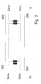
- FIG. 2 the cable connection according to the invention is shown.
- FIG. 3 a section of a schematic diagram is shown.
- FIG. 4 schematic diagram of an embodiment of the invention is shown.
- FIG. 5 is a modification of the embodiment according to FIG. 4 shown.
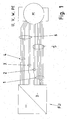
- FIG. 1 It is known to provide between a converter FU and an electric motor M, a cable connection having different lines for low power and high current.
- At least one respective connector is provided for each cable, so that the cable from the motor M, in particular an electric motor, and / or from the inverter FU is separable.
- the inverter FU is arranged in a control cabinet of a system, whereas the motor M in the mechanical part of the system, ie outside the cabinet, is arranged. This results in high cable lengths and complex wiring.
- At least one temperature sensor or a temperature-sensitive switch is arranged in the stator winding of the motor M.
- an angle sensor is arranged on the motor, whose signals contain information about the angular position of the rotor shaft of the electric motor M.
- a brake is arranged on the motor M, the braking force of which acts on the rotor shaft.
- the lines 1 for transmitting the information detected by the angle sensor are arranged in a hybrid cable 5 together with the power lines U, V, W, PE.
- Another cable 6 with low power lines 3 and 2 is necessary because not enough many low power cables can be integrated in the hybrid cable.
- the weak current lines 3 transmit the control voltage for the brake and the low-current lines 2 the analog temperature values detected. Appropriate connectors are providable.
- each track of this encoder are assigned two lines and the encoder has more than one track. The processing of these track signals then takes place in the inverter FU.
- the hybrid cable includes the power lines U, V, W, PE and additionally only a few low-voltage cables.
- the power lines U, V, W, PE are as weak current lines in a first embodiment according to FIG. 2 and 3 only two data + and data- lines are needed for a differential signal transmission along with supply lines GND and VDD.
- FIG. 3 shown is a galvanic isolation, so isolation realized by using a converter side and a motor-side transformer.
- the data can be arranged here as a data word, with each data word being composed by way of example by arranging brake-related data in a first word component, temperature sensor-related data in a second word component and angle sensor-related data in a third word component.
- Communication over the signal lines is bidirectional executable, so that the temperature sensor-related data and angle sensor-related data from the motor M to the inverter FU and the brake-related data from the inverter FU are transmitted to the motor M.
- the process data position and temperature can now be transferred from the motor to the inverter and the process data "brake on” or “brake off” coded by the inverter FU can be transmitted to the motor M.
- the low-voltage power supply lines can supply the brake, the temperature sensor and / or the encoder. For this example, 24 volts are applied between VDD and GND.
- the brake in this case comprises an electronic circuit which controls an electromagnet of the brake.
- the electronic circuit is supplied via said low-power supply lines VDD and GND.
- a power semiconductor switch encompassed by the electronic circuit controls the current of the electromagnet and receives its drive signal via the data lines Data + and Data-.
- the motor-side and / or converter-side galvanic isolation reduces interference.
- a circuit board is arranged in the motor M, which are supplied to the signals of the sensors and from which the electromagnet of the brake, so the actuator, its associated control current is supplied.
- a hybrid connector part is arranged as in the motor housing, in which the hybrid cable 20 is plug-connected by means of a corresponding arranged on an end portion of the hybrid cable 20 mating connector part and the associated lines are passed from the connector part to the circuit board.
- the hybrid cable 20 includes four lines 21 for low power, in particular two lines for the differential signal transmission and two lines for the supply voltage passage, and lines 22 for power, especially high current, ie motor phases U, V, W and neutral PE.
- the circuit board with its equipped electronic components as part of the angle sensor executable executes. Namely, if magnetic field-sensitive sensors, in particular Hall sensors and / or Wiegandsensoren are arranged on the circuit board and the printed circuit board is arranged in such a way that these magnetic field sensitive sensors are arranged opposite to a rotating rotatably connected to the rotor shaft of the motor part, are on the rotating part Permanent magnets can be arranged, which are detectable by the magnetic field-sensitive sensors and thus the angular position can be detected.
- the circuit board is exemplified fastened to a flange or other housing part of the engine.
- the control current for the electromagnet of the brake is controllable.
- an electronic circuit or a component can be provided on the printed circuit board, which is referred to as a converter and forms an interface between the sensor signals and the Sigrialtechnischen Data + and Data-.
- a memory is also provided on the printed circuit board, to which parameters to be stored via the signal lines can be fed.
- motor-related data in this memory which is preferably designed as a long-term memory, such as EEPROM or the like, or at least includes such a memory component, so that even in case of power failure, the stored parameters are not lost.
- a fan is preferably used, wherein the permanent magnets in the fan ring and / or in the fan blades and / or arranged in an outer circumference arranged shipsleitring the fan.
- an electromagnetically actuated brake is arranged on the motor. With sufficient current to the electromagnet, so brake coil, a Anchor plate attracted by the electromagnet, whereby a counteracting spring force is overcome. The armature disc releases the brake pads, whereby the brake is released. If there is insufficient energization, the spring force generating spring elements press the armature disk on the brake pad carrier, the brake pads are thus in turn pressed onto a braking surface. The brake then falls and generates braking torque or braking force.
- the brake pad carrier is axially displaceable and rotationally fixed on the rotor.
- the armature disk is arranged axially displaceable and non-rotatably arranged on the motor housing or stator.
- two of the low current lines 21 are power lines, which are operated to have two voltage states, illustratively a low voltage such as 7.5 volts, or alternatively a higher voltage 24 volts.
- the brake coil 30 is supplied and a voltage adjustment circuit 32, an electronic circuit 31, such as angle sensor with evaluation electronics or the like.
- the voltage adjustment circuit 32 generates a supply voltage of 5 volts for the electronic shading 31 from the voltage between the supply lines (GND, 24V / 7.5 V).
- the brake drive information is encoded with the electronic circuit 31 always powered.
- the information for brake control is thus independent of the data lines Data + and Dataaus woolbar. Even more data can be transmitted as a binary data stream by using the two voltage levels as HIGH and LOW signals.
- an angle sensor is preferably used with evaluation.
- a controllable semiconductor switch 40 in particular IGBT or MOSFET, is used to control the coil current, which is supplied from a drive circuit for the semiconductor switch 40, not shown, to which the supply voltage, only at the high voltage level, in particular 24 volts, the switch 40 in the conductive state is added.
- the brake is dimensioned so that it remains ventilated at both voltage levels, ie HIGH and LOW. Thus, the binary data stream is then transferable without disturbing the braking state.
- a bidirectional communication is executable.
- a half-duplex method is used herein.
- two further low-current lines are arranged as signal lines in the hybrid cable
Description
Die Erfindung betrifft ein Antriebssystem und ein Verfahren zum Betreiben eines Antriebssystems.The invention relates to a drive system and a method for operating a drive system.
Es ist bekannt, als Antriebssystem einen umrichtergespeisten Motor zu verwenden, wobei der Umrichter mit dem Motor über ein Kabel verbunden ist.It is known to use as a drive system, a converter-fed motor, wherein the inverter is connected to the motor via a cable.
Aus der
Aus der
Aus der
Aus der
Aus der
Aus der
Aus der
Der Erfindung liegt daher die Aufgabe zugrunde, eine ein Antriebssystem weiterzubilden, wobei es mit geringem Installationsaufwand in einer Anlage installierbar sein soll.The invention is therefore the object of developing a drive system, where it should be installable with low installation costs in a system.
Erfindungsgemäß wird die Aufgabe bei dem Antriebssystem nach den in Anspruch 1 und bei dem Verfahren nach den in Anspruch 13 angegebenen Merkmalen gelöst.According to the invention the object is achieved in the drive system according to the features specified in
Wichtige Merkmale der Erfindung bei dem Antriebssystem sind, dass das Antriebssystem zumindest einen Elektromotor aufweist, welcher von einem Umrichter gespeist wird,
wobei der Umrichter und der Motor über ein Kabelsystem, insbesondere Hybridkabel, verbunden sind,
wobei das Kabelsystem Starkstromleitungen zur Versorgung des Motors und Schwachstromleitungen aufweist,
wobei die Schwachstromleitungen zwei Versorgungsleitungen zur Versorgung einer motorseitigen elektronischen Schaltung aufweisen,
wobei die Versorgungsleitungen die Bremsspule einer Bremse versorgen, insbesondere zur Erzeugung eines dem vom Motor erzeugten Drehmoment entgegenwirkenden Drehmoments beziehungswiese einer der vom Motor erzeugten Kraft entgegenwirkenden Kraft,
wobei die elektronische Schaltung über eine Spannungsanpassungsschaltung aus den Versorgungsleitungen versorgt wird, insbesondere zur Bereitstellung einer unabhängig vom Spannungspegel der Versorgungsleitungen erzeugten Versorgungsspannung für die elektronische Schattung,
insbesondere wobei der Motor ein Linearmotor oder rotatorischer Motor ist, wobei die beiden Versorgungsleitungen derart betrieben werden, dass sie entweder einen ersten höheren Spannungszustand, oder alternativ einen zweiten niedrigeren Spannungszustand aufweisen, und wobei diese beiden Spannungspegel zur Codierung einer Bremsansteuerungsinformation dienen.Important features of the invention in the drive system are that the drive system has at least one electric motor, which is fed by a converter,
wherein the converter and the motor are connected via a cable system, in particular hybrid cables,
the cable system having power lines for supplying the motor and low-voltage lines,
wherein the weak current lines have two supply lines for supplying a motor-side electronic circuit,
wherein the supply lines supply the brake coil with a brake, in particular for generating a torque counteracting the torque generated by the motor or a force counteracting the force generated by the motor,
wherein the electronic circuit is supplied from the supply lines via a voltage adjustment circuit, in particular for providing a supply voltage for the electronic shading generated independently of the voltage level of the supply lines,
in particular, wherein the motor is a linear motor or rotary motor, the two supply lines being operated to have either a first higher voltage state, or alternatively a second lower voltage state, and wherein these two voltage levels are for encoding a brake drive information.
Bei einer vorteilhaften Ausgestaltung ist die Bremse, insbesondere die Wicklungszahl, die geometrischen Abmessungen und die Materialeigenschaften der Bremse mit Bremsspule, derart dimensioniert, dass sie bei einem Spannungspegel, welcher die Versorgungsspannung der elektronischen Schaltung überschreitet, gelüftet bleibt. Von Vorteil ist dabei, dass die Bremse sogar direkt aus den Versorgungsleitungen ansteuerbar ist.In an advantageous embodiment, the brake, in particular the winding number, the geometric dimensions and the material properties of the brake with brake coil, dimensioned such that it remains ventilated at a voltage level which exceeds the supply voltage of the electronic circuit. The advantage here is that the brake is even controlled directly from the supply lines.
Bei einer vorteilhaften Ausgestaltung sind als elektronische Schaltung am Motor zumindest ein Sensor und ein Aktor angeordnet. Von Vorteil ist dabei, dass als Sensor beispielsweise ein Winkelsensor verwendbar ist.In an advantageous embodiment, at least one sensor and an actuator are arranged as an electronic circuit on the motor. The advantage here is that, for example, an angle sensor can be used as a sensor.
Bei einer vorteilhaften Ausgestaltung teilt die Spannungsanpassungsschaltung eine Versorgungsspannung für die elektronische Schaltung aus dem auf den Versorgungsleitungen herrschenden Spannungspegel herab. Von Vorteil ist dabei, dass für die elektronische Schaltung eine gleichmäßige Spannung bereit gestellt wird.In an advantageous embodiment, the voltage adjustment circuit divides a supply voltage for the electronic circuit from the voltage level prevailing on the supply lines. The advantage here is that a uniform voltage is provided for the electronic circuit.
Bei einer vorteilhaften Ausgestaltung ist im Strompfad zwischen einer Versorgungsleitung und der Bremsspule ein steuerbarer Schalter, insbesondere IGBT oder MOSFET, angeordnet zur Steuerung des Bremsspulenstroms. Von Vorteil ist dabei, dass der Bremsspulenstrom vom Pegel abhängig steuerbar ist, wobei sogar eine Schnellerregung der Bremse ausführbar ist, wobei ein Zeitglied in der Ansteuerschaltung für den Schalter verwendet wird. Außerdem ist der Schalter derart von der Ansteuerschaltung steuerbar, dass er offen, solange nicht der höhere der beiden Pegel auf den Versorgungsleitungen anliegt.In an advantageous embodiment, a controllable switch, in particular IGBT or MOSFET, is arranged in the current path between a supply line and the brake coil for controlling the brake coil current. The advantage here is that the brake coil current is dependent on the level controllable, with even a fast excitation of the brake is executable, wherein a timer is used in the drive circuit for the switch. In addition, the switch is controllable by the drive circuit such that it is open unless the higher of the two levels is applied to the supply lines.
Bei einer vorteilhaften Ausgestaltung sind am Motor zumindest ein Sensor und ein Aktor angeordnet,
wobei der Umrichter und der Motor über ein Hybridkabel verbunden sind,
wobei das Hybridkabel Starkstromleitungen und Schwachstromleitungen aufweist,
wobei als Schwachstromleitungen zumindest zwei oder nur zwei Signalleitungen und zwei Versorgungsleitungen, insbesondere zur 24 Volt-Versorgung, verwendet sind,
wobei über die Signalleitungen die von den Sensoren erfassten Werte und, - insbesondere zeitlich versetzt - , die für den Aktor bestimmten Ansteuerdaten übertragbar sind.In an advantageous embodiment, at least one sensor and an actuator are arranged on the motor,
wherein the inverter and the motor are connected via a hybrid cable,
the hybrid cable having power lines and low power lines,
at least two or only two signal lines and two supply lines, in particular for the 24 volt supply, being used as low-current lines,
wherein via the signal lines the values detected by the sensors and, in particular offset in time, the drive data intended for the actuator can be transmitted.
Von Vorteil ist dabei, dass ein einziges Hybridkabel verwendbar ist und somit nur ein geringer Installationsaufwand ermöglicht ist. Da einem Kabel nur ein urnrichterseitiger Steckverbinder und/oder ein motorseitiger Steckverbinder zugeordnet wird, sind erhebliche Kosten einsparbar und die Verkabelung einer Anlage vereinfachbar, also übersichtlicher installierbar.The advantage here is that a single hybrid cable is used and thus only a small installation effort is possible. Since a cable only one urnrichterseitiger connector and / or a motor-side connector is assigned, considerable costs can be saved and the wiring of a system simplified, so clearly installed.
Bei einer vorteilhaften Ausgestaltung ist am Motor ein Temperatursensor, insbesondere ein in den Statorwicklungen des Motors angeordneter Temperatursensor, und/oder ein Winkelsensor angeordnet und ist als Aktor eine elektromagnetisch betätigbare Bremse, deren Bremsmoment der Rotorwelle des Motors zuleitbar. Von Vorteil ist dabei, dass verschiedene Sensoren verwendbar sind und die erfassten Sensordaten zusammen, also ein digitaler Datenstrom, dem Umrichter und dessen Steuerelektronik zuleitbar sind, so dass die erfassten Sensordaten beim Regeln des Antriebs verwendbar sind.In an advantageous embodiment, a temperature sensor, in particular arranged in the stator windings of the motor temperature sensor, and / or an angle sensor is arranged on the motor and is an actuator as an electromagnetically actuated brake whose braking torque of the rotor shaft of the motor zuleitbar. The advantage here is that different sensors can be used and the detected sensor data together, so a digital data stream, the inverter and its control electronics are zuleitbar so that the detected sensor data can be used when controlling the drive.
Bei einer vorteilhaften Ausgestaltung ist das Hybridkabel über eine Steckverbindung mit dem Motor und/oder über eine andere Steckverbindung mit dem Umrichter verbunden. Von Vorteil ist dabei, dass ein Hybridsteckverbinderteil verwendbar ist und somit Starkstromleitungen und Schwachstromleitungen gemeinsam verbindbar sind und somit eine einfache Installation ausführbar ist.In an advantageous embodiment, the hybrid cable is connected via a plug connection with the motor and / or via a different plug connection with the converter. The advantage here is that a hybrid connector part is used and thus power cables and low power cables are connected together and thus a simple installation is executable.
Bei einer vorteilhaften Ausgestaltung ist ein Mittel zur galvanischen Trennung, insbesondere ein Transformator, zwischen Motor und Leitungen des Hybridkabels, insbesondere Schwachstromleitungen des Hybridkabels angeordnet.
und/oder
ist ein Mittel zur galvanischen Trennung, insbesondere ein Transformator, zwischen Motor und Leitungen des Hybridkabels, insbesondere Schwachstromleitungen des Hybridkabels angeordnet. Von Vorteil ist dabei, dass eine verringerte Störeinwirkung von Fremdsignalen oder sonstigem Rauschen erreichbar ist. Insbesondere wird das Signal-Rauschverhältnis verbessert und die Sicherheit erhöht.In an advantageous embodiment, a means for electrical isolation, in particular a transformer, between the engine and lines of the hybrid cable, in particular low-current lines of the hybrid cable is arranged.
and or
is a means for electrical isolation, in particular a transformer, between the engine and lines of the hybrid cable, in particular low-voltage cables of the hybrid cable arranged. The advantage here is that a reduced interference from external signals or other noise can be achieved. In particular, the signal-to-noise ratio is improved and security is increased.
Bei einer vorteilhaften Ausgestaltung fungieren die Signalleitungen als differentielle Signalübertragungsleitungen. Von Vorteil ist dabei, dass ein besonders hohes Signal-Rauschverhältnis erreichbar ist und die Fehlübertragungen vermindert werden.In an advantageous embodiment, the signal lines function as differential signal transmission lines. The advantage here is that a particularly high signal-to-noise ratio can be achieved and the transmission errors are reduced.
Bei einer vorteilhaften Ausgestaltung umfassen die Starkstromleitungen die Motorphasen-Zuleitungen (U,V,W,) und einen Nullleiter (PE). Von Vorteil ist dabei, dass der Starkstrom, also mehr als 1 Ampere übertragbar ist und das Hybridkabel diese Leitungen mit entsprechend großem Querschnitt aufnimmt. Die zu diesem Wechselstrom zugehörige Motorspannung liegt zwischen 100 Volt und 1000 Volt Effektivspannung.In an advantageous embodiment, the power lines include the motor phase leads (U, V, W,) and a neutral conductor (PE). The advantage here is that the power, ie more than 1 ampere is transferable and the hybrid cable receives these lines with a correspondingly large cross-section. The motor voltage associated with this alternating current is between 100 volts and 1000 volts rms voltage.
Bei einer vorteilhaften Ausgestaltung ist im Motor ein ansteuerbarer Halbleiterschalter angeordnet, dem das Ansteuersignal vom Umrichter über die Signalleitungen des Hybridkabels zuführbar ist und welcher den dem Elektromagneten der Bremse zugeführten Strom steuert. Von Vorteil ist dabei, dass der Strom steuerbar ist und somit von der elektromagnetisch betätigbaren Bremse als steuerbarer Aktor ein Bremsmoment auf die Rotorwelle leitbar ist.In an advantageous embodiment, a controllable semiconductor switch is arranged in the motor, to which the drive signal from the converter via the signal lines of the hybrid cable can be supplied and which controls the electromagnet of the brake supplied current. The advantage here is that the current is controllable and thus a braking torque can be conducted to the rotor shaft of the electromagnetically actuated brake as a controllable actuator.
Bei einer vorteilhaften Ausgestaltung ist im Motor eine Leiterplatte angeordnet, insbesondere an einem zumindest teilweise gehäusebildenden Teil, und auf der Leiterplatte der Halbleiterschalter bestückt ist,
wobei auf der Leiterplatte auch ein magnetfeldsensitiver Sensor, insbesondere Halisensor und/oder Wiegandsensor, bestückt ist, welcher einem drehbar gelagerten Teil, insbesondere Lüfter, gegenüberstehend angeordnet ist, wobei am drehbar gelagerten Teil Dauermagnete angeordnet sind, die von dem magnetfeldsensitiven Sensor detektierbar sind beim Vorbeidrehen. Von Vorteil ist dabei, dass eine integrierte kompakte Ausführung ermöglicht ist.In an advantageous embodiment, a printed circuit board is arranged in the motor, in particular on an at least partially housing-forming part, and on the circuit board of the semiconductor switch is equipped,
wherein on the circuit board, a magnetfeldsensitiver sensor, in particular Halisensor and / or Wiegandsensor is equipped, which is arranged rotatably mounted part, in particular fan, opposite, wherein on the rotatably mounted part permanent magnets are arranged, which are detectable by the magnetic field sensitive sensor when passing , The advantage here is that an integrated compact design is possible.
Bei einer vorteilhaften Ausgestaltung ist auf der Leiterplatte eine Umsetzer angeordnet, welcher die über die Signalleitungen als digitale Information übertragenen Daten empfängt und daraus die Ansteuerinformationen für den Aktor, insbesondere den Halbleiterschalter, herausfiltert und die von den Sensoren, insbesondere Winkelsensor und Temperatursensor, zugeleiteten Signale als digitalen Datenstrom über die Signalleitungen an den Umrichter leitet. Von Vorteil ist dabei, dass mittels des Umsetzers nur wenige Signalleitungen notwendig sind, nämlich nur eine Datenleitung, die durch die beiden differentiell arbeitenden Signalleitungen realisiert sind.In an advantageous embodiment, a converter is arranged on the circuit board, which receives the data transmitted via the signal lines as digital information and from which the control information for the actuator, in particular the semiconductor switch, filters out and passes the signals supplied by the sensors, in particular angle sensor and temperature sensor, as a digital data stream via the signal lines to the converter. The advantage here is that only a few signal lines are necessary by means of the converter, namely only one data line, which are realized by the two differentially operating signal lines.
Bei einer vorteilhaften Ausgestaltung sind im Hybridkabel zwei weitere Signalleitungen angeordnet, so dass das Antriebssystem in sicherheitsgerichteten Anlagen betreibbar ist,
insbesondere wobei der digitale Datenstrom redundant übertragen wird oder Prüfinformationen über den digitalen Datenstrom übertragen werden. Von Vorteil ist dabei, dass die Sicherheit in einfacher Weise erhöhbar ist und trotzdem eine einfache Installation erreichbar ist, da nur ein Hybridkabel verwendet ist.In an advantageous embodiment, two further signal lines are arranged in the hybrid cable, so that the drive system can be operated in safety-related systems,
in particular wherein the digital data stream is transmitted redundantly or test information is transmitted via the digital data stream. The advantage here is that the security can be increased in a simple manner and still a simple installation is achievable, since only a hybrid cable is used.
Wichtige Merkmale bei dem Verfahren zum Betreiben eines Antriebssystems sind, dass das Antriebssystem zumindest einen Elektromotor aufweist, welcher von einem Umrichter gespeist wird,
wobei der Umrichter und der Motor über ein Kabelsystem, insbesondere Hybridkabel, verbunden sind,
wobei das Kabelsystem Starkstromleitungen zur Versorgung des Motors und Schwachstromleitungen aufweist,
wobei die Schwachstromleitungen zwei Versorgungsleitungen zur Versorgung einer motorseitigen elektronischen Schaltung aufweisen,
wobei die Versorgungsleitungen auch die Bremsspule einer Bremse, insbesondere einer mit dem Motor mechanisch verbundenen Bremse, versorgen, insbesondere zur Erzeugung eines dem vom Motor erzeugten Drehmoment entgegenwirkenden Drehmoments beziehungswiese einer der vom Motor erzeugten Kraft entgegenwirkenden Kraft,
wobei die elektronische Schaltung über eine Spannungsanpassungsschaltung aus den Versorgungsleitungen versorgt wird, insbesondere wobei eine unabhängig vom Spannungspegel der Versorgungsleitungen erzeugte Versorgungsspannung für die elektronische Schaltung bereit gestellt wird,
wobei zur Übertragung einer Bremsansteuerungsinformation auf den Versorgungsleitungen verschiedene Pegel umrichterseitig angelegt werden, insbesondere wobei die Signale motorseitig decodiert werden,
insbesondere wobei der Motor ein Linearmotor oder rotatorischer Motor ist.Important features in the method for operating a drive system are that the drive system has at least one electric motor which is fed by an inverter,
wherein the converter and the motor are connected via a cable system, in particular hybrid cables,
the cable system having power lines for supplying the motor and low-voltage lines,
wherein the weak current lines have two supply lines for supplying a motor-side electronic circuit,
wherein the supply lines also supply the brake coil of a brake, in particular a brake mechanically connected to the motor, in particular for generating a torque counteracting the torque generated by the motor or a force counteracting the force generated by the motor,
wherein the electronic circuit is supplied from the supply lines via a voltage adjustment circuit, in particular wherein a supply voltage is provided for the electronic circuit independently of the voltage level of the supply lines,
wherein for the transmission of a brake drive information on the supply lines different levels are applied to the inverter side, in particular wherein the signals are decoded on the motor side,
in particular, wherein the motor is a linear motor or rotary motor.
Von Vorteil ist dabei, dass die Versorgungsleitungen zum Übertragen von Information verwendbar sind. Infolge der Spannungsanpassungsschaltung ist trotz der veränderlichen Spannungspegel auf den Versorgungsleitungen eine gleichmäßige Spannung für die elektronische Schaltung, insbesondere Winkelsensor, bereit stellbar. Vorteiligerweise lässt sich die Erfindung auf alle elektromotorischen Antriebe mit Bremse anwenden, also auch auf Linearmotoren und rotatorische Motoren.The advantage here is that the supply lines for transmitting information can be used. As a result of the voltage adjustment circuit, a uniform voltage for the electronic circuit, in particular angle sensor, can be set despite the variable voltage levels on the supply lines. Advantageously, the invention can be applied to all electric motor drives with brake, including on linear motors and rotary motors.
Bei einer vorteilhaften Ausgestaltung werden zwei verschiedene Pegel zur Codierung auf den Versorgungsleitungen verwendet, wobei bei dem niedrigeren Pegel ein Lüften der Bremse bewirkt wird und bei dem höheren der beiden Pegel ein Einfallen der Bremse bewirkt wird. Von Vorteil ist dabei, dass eine Codierung zur Ansteuerung der Bremse in einfacher Weise ermöglicht ist.In an advantageous embodiment, two different levels are used for coding on the supply lines, wherein at the lower level, a release of the brake is effected and at the higher of the two levels, a collapse of the brake is effected. The advantage here is that a coding for controlling the brake is made possible in a simple manner.
Bei einer vorteilhaften Ausgestaltung werden auf den Signalleitungen Daten derart digital codiert übertragen, dass die zeitlichen Abschnitte negativer und positiver Spannung gleich lang sind, insbesondere wobei die zeitlichen Abschnitte jeweils derart kurz sind, dass als Mittel zur galvanischen Trennung verwendete Transformatoren nicht gesättigt werden.In an advantageous embodiment, data are transmitted in a digitally coded manner on the signal lines in such a way that the time segments of negative and positive voltage are of equal length, in particular wherein the time segments are each so short that transformers used as means for galvanic isolation are not saturated.
Bei einer vorteilhaften Ausgestaltung werden auf den Signalleitungen Daten im Manchestercode übertragen, insbesondere wobei die Daten bidirektional übertragen werden, insbesondere wobei ein half Duplex Verfahren verwendet werden, insbesondere wobei die Daten der Sensoren und Aktoren seriell hintereinander in einem Datenwort übertragen werden.
Von Vorteil ist dabei, dass eine effektive störarme Signalübertragung bidirektional herstellbar ist.In an advantageous embodiment, data are transmitted in the Manchester code on the signal lines, in particular wherein the data is transmitted bidirectionally, in particular wherein a half-duplex method is used, in particular wherein the Data from the sensors and actuators are transmitted serially one behind the other in a data word.
The advantage here is that an effective low-noise signal transmission can be produced bidirectionally.
Weitere Vorteile ergeben sich aus den Unteransprüchen. Die Erfindung ist nicht auf die Merkmalskombination der Ansprüche beschränkt. Für den Fachmann ergeben sich weitere sinnvolle Kombinationsmöglichkeiten von Ansprüchen und/oder einzelnen Anspruchsmerkmalen und/oder Merkmalen der Beschreibung und/oder der Figuren, insbesondere aus der Aufgabenstellung und/oder der sich durch Vergleich mit dem Stand der Technik stellenden Aufgabe.Further advantages emerge from the subclaims. The invention is not limited to the combination of features of the claims. For the skilled person, further meaningful combination possibilities of claims and / or individual claim features and / or features of the description and / or figures, in particular from the task and / or posing by comparison with the prior art task arise.
Die Erfindung wird nun anhand von schematischen Abbildungen näher erläutert:The invention will now be explained in more detail with reference to schematic illustrations:
In der
In der
In der
In der
In der
Im Stand der Technik gemäß
Dabei sind für jedes Kabel zumindest ein jeweiliger Steckverbinder vorgesehen, damit das Kabel vom Motor M, insbesondere ein Elektromotor, und/oder vom Umrichter FU trennbar ist. Vorzugsweise wird der Umrichter FU in einem Schaltschrank einer Anlage angeordnet, wohingegen der Motor M im maschinenbaulichen Teil der Anlage, also außerhalb des Schaltschrankes, angeordnet ist. Hierdurch ergeben sich hohe Kabellängen und komplexe Verdrahtungen.At least one respective connector is provided for each cable, so that the cable from the motor M, in particular an electric motor, and / or from the inverter FU is separable. Preferably, the inverter FU is arranged in a control cabinet of a system, whereas the motor M in the mechanical part of the system, ie outside the cabinet, is arranged. This results in high cable lengths and complex wiring.
In der Statorwicklung des Motors M ist zumindest ein Temperatursensor oder ein temperaturempfindlicher Schalter angeordnet. Außerdem ist ein Winkelsensor am Motor angeordnet, dessen Signale Information über die Winkellage der Rotorwelle des Elektromotors M enthalten. Des Weiteren ist am Motor M eine Bremse angeordnet, deren Bremskraft auf die Rotorwelle wirkt.In the stator winding of the motor M, at least one temperature sensor or a temperature-sensitive switch is arranged. In addition, an angle sensor is arranged on the motor, whose signals contain information about the angular position of the rotor shaft of the electric motor M. Furthermore, a brake is arranged on the motor M, the braking force of which acts on the rotor shaft.
Somit sind als Verkabelung zwischen Umrichter FU und Motor M nicht nur die Starkstromleitungen 4 für die Phasen U, V, W des Motors M samt der zugehörige Nullleitung PE verwendet sondern auch Schwachstromleitungen. Dabei sind beispielhaft die Leitungen 1 zur Übertragung der vom Winkelsensor erfassten Information in einem Hybridkabel 5 zusammen mit den Starkstromleitungen U,V,W, PE angeordnet. Ein weiteres Kabel 6 mit Schwachstromleitungen 3 und 2 ist notwendig, da im Hybridkabel nicht ausreichend viele Schwachstromleitungen integrierbar sind. Dabei übertragen die Schwachstromleitungen 3 die Steuerspannung für die Bremse und die Schwachstromleitungen 2 die analog erfassten Temperaturwerte. Entsprechende Steckverbinder sind vorsehbar.Thus, not only the
Zur Übertragung der Signale des Winkelsensors sind 6 oder mehr Leitungen notwendig, das jeder Spur dieses Gebers zwei Leitungen zugeordnet sind und der Geber mehr als eine Spur aufweist. Die Verarbeitung dieser Spursignale erfolgt dann im Umrichter FU.To transmit the signals of the angle sensor 6 or more lines are necessary, each track of this encoder are assigned two lines and the encoder has more than one track. The processing of these track signals then takes place in the inverter FU.
Bei der Erfindung gemäß den
Dabei umfasst das Hybridkabel die Starkstromleitungen U,V,W, PE und zu sätzlich nur wenige Schwachstromleitungen. Dabei sind als Schwachstromleitungen in einem ersten Ausführungsbeispiel gemäß
Wie in
Durch Verwendung des Manchester Codes als Codierung bei der Signalübertragung ist sicher gestellt, dass die zeitlichen Abschnitte mit negativer und positiver Spannung gleich lang sind und die Transformatoren nicht gesättigt werden. Die Daten sind hierbei als Datenwort anordenbar, wobei jedes Datenwort beispielhaft zusammengesetzt ist, indem in einem ersten Wortanteil bremsenbezogene Daten, in einem zweiten Wortanteil temperatursensorbezogene Daten und in einem dritten Wortanteil winkelsensorbezogene Daten angeordnet werden. Die Kommunikation über die Signalleitungen ist bidirektional ausführbar, so dass die temperatursensorbezogenen Daten und winkelsensorbezogenen Daten vom Motor M an den Umrichter FU und die bremsenbezogenen Daten vom Umrichter FU an den Motor M übertragen werden.By using the Manchester code as coding in the signal transmission is ensured that the periods of time with negative and positive voltage are the same length and the transformers are not saturated. The data can be arranged here as a data word, with each data word being composed by way of example by arranging brake-related data in a first word component, temperature sensor-related data in a second word component and angle sensor-related data in a third word component. Communication over the signal lines is bidirectional executable, so that the temperature sensor-related data and angle sensor-related data from the motor M to the inverter FU and the brake-related data from the inverter FU are transmitted to the motor M.
Über diese Schnittstelle zwischen Umrichter und Motor können nun die Prozessdaten Lage und Temperatur vom Motor zum Umrichter übertragen und das Prozessdatum "Bremse ein " oder "Bremse aus" codiert vom Umrichter FU zum Motor M übertragen werden.Using this interface between inverter and motor, the process data position and temperature can now be transferred from the motor to the inverter and the process data "brake on" or "brake off" coded by the inverter FU can be transmitted to the motor M.
Über die Schwachstrom-Versorgungsleitungen ist die Bremse, der Temperatursensor und/oder der Geber versorgbar. Hierzu werden beispielhaft 24 Volt zwischen VDD und GND angelegt.The low-voltage power supply lines can supply the brake, the temperature sensor and / or the encoder. For this example, 24 volts are applied between VDD and GND.
Die Bremse umfasst hierbei eine elektronische Schaltung, welche einen Elektromagneten der Bremse ansteuert. Hierzu wird die elektronische Schaltung über die genannten Schwachstrom-Versorgungsleitungen VDD und GND versorgt. Ein von der elektronischen Schaltung umfasster Leistungshalbleiterschalter steuert den Strom des Elektromagneten und empfängt sein Ansteuersignal über die Signalleitungen Data+ und Data-.The brake in this case comprises an electronic circuit which controls an electromagnet of the brake. For this purpose, the electronic circuit is supplied via said low-power supply lines VDD and GND. A power semiconductor switch encompassed by the electronic circuit controls the current of the electromagnet and receives its drive signal via the data lines Data + and Data-.
Die motorseitige und/oder umrichterseitige galvanische Trennung vermindert Störsignaleinwirkungen.The motor-side and / or converter-side galvanic isolation reduces interference.
Vorzugsweise ist im Motor M eine Leiterplatte angeordnet, welcher die Signale der Sensoren zugeführt werden und von welcher dem Elektromagneten der Bremse, also des Aktors, sein ihm zugeordneter Steuerstrom zugeführt wird. Hierzu wird als am Motorgehäuse ein Hybridsteckverbinderteil angeordnet, in welches das Hybridkabel 20 mittels eines entsprechenden an einem Endbereich des Hybridkabels 20 angeordneten Gegensteckverbinderteils steckverbindbar ist und die zugehörigen Leitungen vom Steckverbinderteil zur Leiterplatte durchgeleitet werden.Preferably, a circuit board is arranged in the motor M, which are supplied to the signals of the sensors and from which the electromagnet of the brake, so the actuator, its associated control current is supplied. For this purpose, a hybrid connector part is arranged as in the motor housing, in which the
Das Hybridkabel 20 umfasst vier Leitungen 21 für Schwachstrom, insbesondere zwei Leitungen für die differentielle Signalübertragung und zwei Leitungen für die Versorgungsspannungsdurchleitung, und Leitungen 22 für Leistung, insbesondere Starkstrom, also Motorphasen U, V, W und Nullleiter PE.The
Vorteiligerweise ist hierbei die Leiterplatte mit auf ihr bestückten elektronischen Bauelementen als Teil des Winkelsensors ausführbar. Wenn nämlich auf der Leiterplatte magnetfeldsensitive Sensoren, insbesondere Hallsensoren und/oder Wiegandsensoren, angeordnet werden und die Leiterplatte derart im Motor angeordnet wird, dass diese magnetfeldsensitiven Sensoren einem drehenden, mit der Rotorwelle des Motors drehfest verbundenen Teil gegenüberstehend angeordnet sind, sind auf dem drehenden Teil Dauermagnete anordenbar, die von den magnetfeldsensitiven Sensoren detektierbar sind und somit die Winkelstellung erfassbar ist. Die Leiterplatte ist dabei beispielhaft an einem Flanschteil oder sonstigen Gehäuseteil des Motors befestigbar. Somit sind dieser Leiterplatte auch die weiter zugeleiteten Sensorsignale zuleitbar, insbesondere also diejenigen des Temperatursensors. Von der Leiterplatte ausgehend ist auch der Steuerstrom für den Elektromagneten der Bremse steuerbar. Vorzugsweise ist also auf der Leiterplatte auch eine elektronische Schaltung oder ein Bauteil vorsehbar, das als Umsetzer bezeichnet wird und eine Schnittstelle zwischen den Sensorsignalen und den Sigrialleitungen Data+ und Data- bildet. Somit ist ein Zusammenfassen der ausgehenden Datenströme und ein Separieren des eingehenden Datenstroms direkt auf derjenigen Leiterplatte ermöglicht, die auch die zur Detektion der Dauermagneten des drehenden Teils entsprechend bestückt ist. Somit ist eine bidirektionale Datenübertragung ermöglicht. Auf der Leiterplatte ist auch ein Speicher vorgesehen, dem über die Signalleitungen abzuspeichernde Parameter zuleitbar sind. Somit ist bei dem Betrieb des Winkelsensors eine Berücksichtigung dieser Parameter ermöglicht. Außerdem sind motorbezogene Daten in diesem Speicher, der vorzugsweise als Langzeitspeicher, wie EEPROM oder dergleichen, ausgeführt wird oder zumindest einen solchen Speicheranteil umfasst, so dass auch bei Stromausfall die gespeicherten Parameter nicht verloren gehen.Advantageously, in this case, the circuit board with its equipped electronic components as part of the angle sensor executable. Namely, if magnetic field-sensitive sensors, in particular Hall sensors and / or Wiegandsensoren are arranged on the circuit board and the printed circuit board is arranged in such a way that these magnetic field sensitive sensors are arranged opposite to a rotating rotatably connected to the rotor shaft of the motor part, are on the rotating part Permanent magnets can be arranged, which are detectable by the magnetic field-sensitive sensors and thus the angular position can be detected. The circuit board is exemplified fastened to a flange or other housing part of the engine. Thus, this printed circuit board and the further forwarded sensor signals zulleitbar, especially those of the temperature sensor. Starting from the circuit board, the control current for the electromagnet of the brake is controllable. Preferably, therefore, an electronic circuit or a component can be provided on the printed circuit board, which is referred to as a converter and forms an interface between the sensor signals and the Sigrialleitungen Data + and Data-. Thus, a summarization of the outgoing data streams and a separation of the incoming data stream is made possible directly on that circuit board, which is also equipped to detect the permanent magnet of the rotating part accordingly. Thus, a bidirectional data transmission is possible. A memory is also provided on the printed circuit board, to which parameters to be stored via the signal lines can be fed. Thus, in the operation of the angle sensor allows consideration of these parameters. In addition, motor-related data in this memory, which is preferably designed as a long-term memory, such as EEPROM or the like, or at least includes such a memory component, so that even in case of power failure, the stored parameters are not lost.
Als drehendes Teil ist vorzugsweise ein Lüfter verwendet, wobei die Dauermagnete im Lüfterring und/oder in den Lüfterflügeln und/oder in einem am Außenumfang angeordneten Luftleitring des Lüfters angeordnet sind.As a rotating part, a fan is preferably used, wherein the permanent magnets in the fan ring and / or in the fan blades and / or arranged in an outer circumference arranged Luftleitring the fan.
Am Motor ist eine elektromagnetisch betätigbare Bremse angeordnet. Bei ausreichender Bestromung deren Elektromagneten, also Bremsspule, wird eine Ankerscheibe angezogen vom Elektromagneten, wobei eine gegenwirkende Federkraft überwunden wird. Die Ankerscheibe gibt dabei die Bremsbeläge frei, wodurch die Bremse gelüftet ist. Bei nicht ausreichender Bestromung drücken die die Federkraft erzeugenden Federelemente die Ankerscheibe auf den Bremsbelägträger, dessen Bremsbeläge somit wiederum auf eine Bremsfläche gedrückt werden. Die Bremse fällt dann also ein und erzeugt Bremsmoment beziehungsweise Bremskraft. Bei rotatorisch ausgeführtem Motor ist der Bremsbelagträger axial verschieblich und drehfest auf dem Rotor angeordnet. Die Ankerscheibe ist axial verschieblich angeordnet und drehfest am Motorgehäuse beziehungsweise Stator angeordnet.On the motor, an electromagnetically actuated brake is arranged. With sufficient current to the electromagnet, so brake coil, a Anchor plate attracted by the electromagnet, whereby a counteracting spring force is overcome. The armature disc releases the brake pads, whereby the brake is released. If there is insufficient energization, the spring force generating spring elements press the armature disk on the brake pad carrier, the brake pads are thus in turn pressed onto a braking surface. The brake then falls and generates braking torque or braking force. When the motor is rotatory, the brake pad carrier is axially displaceable and rotationally fixed on the rotor. The armature disk is arranged axially displaceable and non-rotatably arranged on the motor housing or stator.
In
Bei Anliegen des niedrigen Spannungspegels, also der beispielhaften 7,5 Volt, wird zwar die elektronische Schaltung 31 versorgt, jedoch bleibt die Bremse noch im eingefallenen Zustand, erzeugt also Bremsmoment beziehungsweise Bremskraft.When concern of the low voltage level, so the exemplary 7.5 volts, while the
Bei Anliegen des hohen Spannungspegels, also der beispielhaften 24 Volt, wird nicht nur die elektronische Schaltung 31 versorgt sondern auch die Bremse wird derart ausreichend bestromt, dass die Bremse gelüftet wird.When concerns the high voltage level, ie the exemplary 24 volts, not only the
Somit ist in den zwei Spannungspegeln die Bremsansteuerungsinformation codiert, wobei die elektronische Schaltung 31 stets versorgt ist. Die Information zur Bremsansteuerung ist also unabhängig von den Datenleitungen Data+ und Dataausführbar. Es sind sogar weitere Daten als binärer Datenstrom übertragbar, indem die beiden Spannungspegel als HIGH und LOW Signale verwendet werden.Thus, in the two voltage levels, the brake drive information is encoded with the
Als elektronische Schaltung 31 ist vorzugsweise ein Winkelsensor mit Auswerteelektronik verwendet.As
In
Bei weiteren erfindungsgemäßen Ausführungsbeispielen wird die Bremse derart dimensioniert, dass sie bei beiden Spannungspegeln, also HIGH und LOW, gelüftet bleibt. Somit ist dann ohne störenden Einfluss auf den Bremszustand der binäre Datenstrom übertragbar.In further embodiments of the invention, the brake is dimensioned so that it remains ventilated at both voltage levels, ie HIGH and LOW. Thus, the binary data stream is then transferable without disturbing the braking state.
Bei weiteren erfindungsgemäßen Ausführungsbeispielen sind nicht nur die genannten Sensoren, also Temperatursensor und Winkelsensor, vorgesehen sondern auch weitere Sensoren, deren Daten dann ebenfalls über die Signalleitungen übertragen werden. Außerdem ist nicht nur die Bremse als Aktor sondern es sind auch weitere Aktoren vorsehbar, wobei die zugehörigen Daten ebenfalls über die Signalleitungen übertragen werden. Hierzu ist wiederum einen bidirektionale Kommunikation ausführbar. Vorzugsweise wird ein half-Duplex-Verfahren hierbei verwendet.In further exemplary embodiments according to the invention, not only the aforementioned sensors, ie temperature sensor and angle sensor, are provided, but also other sensors whose data are then also transmitted via the signal lines. In addition, not only the brake as an actuator but there are also other actuators providable, the associated data are also transmitted via the signal lines. For this purpose, in turn, a bidirectional communication is executable. Preferably, a half-duplex method is used herein.
Bei weiteren erfindungsgemäßen Ausführungsbeispielen werden zwei weitere Schwachstromleitungen als Signalleitungen im Hybridkabel angeordnetIn further exemplary embodiments according to the invention, two further low-current lines are arranged as signal lines in the hybrid cable
- 1 Leitungen für Winkelsensor1 lines for angle sensor
- 2 Leitungen für Temperatursensor2 lines for temperature sensor
- 3 Leitungen für Bremse3 lines for brake
- 4 Leitungen für Leistung, insbesondere Starkstrom4 lines for power, especially high voltage
- 5 Hybridkabel für Leistung und Bremse5 hybrid cables for power and brake
- 6 Kabel für Sensoren6 cables for sensors
- 20 Hybridkabel20 hybrid cables
- 21 Leitungen für Schwachstrom21 lines for low power
- 22 Leitungen für Leistung, insbesondere Starkstrom22 lines for power, in particular high voltage
- 30 Bremsspule30 brake coil
- 31 elektronische Schaltung, wie Winkelsensor mit Auswertelektronik oder dergleichen31 electronic circuit, such as angle sensor with evaluation electronics or the like
- 32 Spannungsanpassungsschaltung32 voltage adjustment circuit
- 40 steuerbarer Halbleiterschalter, insbesondere IGBT oder MOSFET40 controllable semiconductor switch, in particular IGBT or MOSFET
- M ElektromotorM electric motor
- FU UmrichterFU inverter
Claims (15)
- Drive system which comprises at least one electric motor (M) which is fed by a converter (FU),
wherein the converter (FU) and the motor are connected via a cable system, in particular hybrid cables (5, 20),
wherein the cable system comprises high-current lines (4) for supplying the motor and low-current lines (21),
wherein the low-current lines (21) comprise two supply lines for supplying a motor-side electronic circuit (31), in particular for an angle sensor with evaluation electronics,
wherein the supply lines (21) supply the brake coil (30) of a brake, in particular for generating a torque counteracting the torque generated by the motor or a force counteracting the force generated by the motor,
characterised in that
the electronic circuit (31) is supplied from the supply lines (21) via a voltage matching circuit (32), in particular for providing a supply voltage, generated independently of the voltage level of the supply lines (21), for the electronic circuit (31),
in particular wherein the motor is a linear motor or a rotary motor,
wherein the two supply lines (21) are operated in such a way that they have either a first voltage state, in which they provide a low voltage, in particular such as 7.5 volts, or alternatively a second voltage state, in which they provide a higher voltage, in particular such as 24 volts, and
wherein these two voltage levels serve for encoding brake control information. - Drive system according to at least one of the preceding claims,
characterised in that
the brake, in particular the number of windings, the geometrical dimensions and the material properties of the brake with brake coil (30), is dimensioned in such a way that it remains released at a voltage level which exceeds the supply voltage of the electronic circuit. - Drive system according to at least one of the preceding claims,
characterised in that
as the electronic circuit (31) at least one sensor and one actuator are arranged on the motor
and/or in that
in the current path between a supply line and the brake coil (30) a controllable switch, in particular IGBT or MOSFET, is arranged for controlling the brake coil current,
and/or in that
the voltage matching circuit (32) divides down a supply voltage for the electronic circuit (31) from the voltage level prevailing on the supply lines (3). - Drive system according to at least one of the preceding claims,
characterised in that
as the low-current lines (21) at least two or only one or two signal lines (1) and two supply lines (3), in particular for 24 volt supply, are used,
wherein the values acquired by the sensors and, - in particular temporally offset -, the control data determined for the actuator are transmittable via the signal lines (1). - Drive system according to at least one of the preceding claims,
characterised in that
on the motor a temperature sensor, in particular a temperature sensor arranged in the stator windings of the motor, and/or an angle sensor is arranged and as the actuator an electromagnetically actuatable brake, the braking torque of which is suppliable to the rotor shaft of the motor. - Drive system according to at least one of the preceding claims,
characterised in that
the hybrid cable (5, 20) is connected via a plug connection to the motor and/or via another plug connection to the converter (FU) . - Drive system according to at least one of the preceding claims,
characterised in that
a means for galvanic isolation, in particular a transformer, is arranged between the motor and the lines of the hybrid cable (5, 20), in particular the low-current lines (21) of the hybrid cable (5, 20)
and/or
a means for galvanic isolation, in particular a transformer, is arranged between the motor and the lines (21) of the hybrid cable (5, 20), in particular the low-current lines (21) of the hybrid cable (5, 20). - Drive system according to at least one of the preceding claims,
characterised in that
the signal lines (1) function as differential signal transmission lines. - Drive system according to at least one of the preceding claims,
characterised in that
the high-current lines (4, 22) comprise the motor-phase supply lines (U,V,W,) and a neutral conductor (PE). - Drive system according to at least one of the preceding claims,
characterised in that
in the motor a controllable semiconductor switch (40) is arranged, to which the control signal is suppliable from the converter (FU) via the signal lines (1) of the hybrid cable (5, 20) and which controls the current supplied to the electromagnet of the brake. - Drive system according to at least one of the preceding claims,
characterised in that
in the motor a printed circuit board is arranged, in particular on an at least partially housing-forming part, and the semiconductor switch (40) is fitted on the printed circuit board,
wherein a magnetic field-sensitive sensor, in particular Hall sensor and/or Wiegand sensor, is also fitted on the printed circuit board, which sensor is arranged opposite a rotatably mounted part, in particular fan, there being arranged on the rotatably mounted part permanent magnets which are detectable by the magnetic field-sensitive sensor as they rotate past,
and/or in that
on the printed circuit board is arranged a converter which receives the data transmitted via the signal lines (1) as digital information and filters out therefrom the control information for the actuator, in particular the semiconductor switch (40), and forwards the signals, supplied by the sensors, in particular angle sensor and temperature sensor, as a digital data stream via the signal lines (1) to the converter (FU). - Drive system according to at least one of the preceding claims,
characterised in that
two further signal lines (1) are arranged in the hybrid cable (5, 20), so that the drive system is operable in safety-oriented systems,
in particular wherein the digital data stream is transmitted redundantly or check information is transmitted via the digital data stream. - Method for operating a drive system, in particular according to one of the preceding claims,
wherein the drive system comprises at least one electric motor (M) which is fed by a converter (FU),
wherein the converter (FU) and the motor are connected via a cable system, in particular hybrid cables (5, 20),
characterised in that
the cable system comprises high-current lines (4) for supplying the motor and low-current lines (21),
wherein the low-current lines (21) comprise two supply lines for supplying a motor-side electronic circuit (31), in particular for an angle sensor with evaluation electronics,
wherein the supply lines (21) also supply the brake coil (30) of a brake, in particular of a brake mechanically connected to the motor, in particular for generating a torque counteracting the torque generated by the motor or a force counteracting the force generated by the motor,
characterised in that
the electronic circuit (31) is supplied from the supply lines (21) via a voltage matching circuit (32), in particular wherein a supply voltage, generated independently of the voltage level of the supply lines (21), is provided for the electronic circuit (31),
wherein for transmitting brake control information, different levels are applied on the converter-side to the supply lines (21),
namely as the first level a low voltage, in particular such as 7.5 volts, as the second level a higher voltage, in particular such as 24 volts,
in particular wherein the signals are decoded on the motor side,
in particular wherein the motor is a linear motor or a rotary motor. - Method according to at least one of the preceding claims,
characterised in that
two different levels are used for encoding on the supply lines (3),
wherein at the lower level a release of the brake is effected and at the higher of the two levels an application of the brake is effected. - Method according to at least one of the preceding claims,
characterised in that
on the signal lines (1) data is transmitted in such a digitally encoded way that the time periods of negative and positive voltage are of equal length, in particular wherein the time periods are in each case so short that transformers used as means for galvanic isolation are not saturated,
and/or
on the signal lines (1) data is transmitted in the Manchester code,
in particular wherein the data is transmitted bidirectionally, in particular wherein a half-duplex method is used,
in particular wherein the data of the sensors and actuators is transmitted serially one after another in a data word.
Applications Claiming Priority (2)
| Application Number | Priority Date | Filing Date | Title |
|---|---|---|---|
| DE201110100361 DE102011100361A1 (en) | 2011-05-03 | 2011-05-03 | Drive system and method for operating a drive system |
| PCT/EP2012/001584 WO2012149996A2 (en) | 2011-05-03 | 2012-04-12 | Drive system and method for operating a drive system |
Publications (2)
| Publication Number | Publication Date |
|---|---|
| EP2705413A2 EP2705413A2 (en) | 2014-03-12 |
| EP2705413B1 true EP2705413B1 (en) | 2015-06-10 |
Family
ID=45954599
Family Applications (1)
| Application Number | Title | Priority Date | Filing Date |
|---|---|---|---|
| EP12714229.7A Active EP2705413B1 (en) | 2011-05-03 | 2012-04-12 | Drive system and method for operating a drive system |
Country Status (3)
| Country | Link |
|---|---|
| EP (1) | EP2705413B1 (en) |
| DE (1) | DE102011100361A1 (en) |
| WO (1) | WO2012149996A2 (en) |
Cited By (1)
| Publication number | Priority date | Publication date | Assignee | Title |
|---|---|---|---|---|
| DE102018000509A1 (en) | 2017-02-02 | 2018-08-02 | Sew-Eurodrive Gmbh & Co Kg | Hybrid cable with integrated fiber optic cable |
Families Citing this family (7)
| Publication number | Priority date | Publication date | Assignee | Title |
|---|---|---|---|---|
| DE102013007649B4 (en) * | 2013-05-06 | 2018-05-24 | Sew-Eurodrive Gmbh & Co Kg | System and method for operating a system |
| EP2851909B1 (en) * | 2013-09-18 | 2017-08-02 | Siemens Aktiengesellschaft | Drive system with combined control of the brake and transducer |
| DE102013018271B4 (en) * | 2013-10-31 | 2016-05-12 | Sew-Eurodrive Gmbh & Co Kg | drive system |
| DE102015005939B3 (en) * | 2015-05-12 | 2016-08-11 | Sew-Eurodrive Gmbh & Co Kg | Method and system for operating an electrical interface |
| DE102015013290A1 (en) * | 2015-10-15 | 2017-04-20 | Sew-Eurodrive Gmbh & Co Kg | A drive comprising an electric motor fed by a converter via first electrical lines and a brake and method for operating a drive |
| DE102017117090A1 (en) * | 2017-07-28 | 2019-01-31 | Hengstler Gmbh | Method for controlling a braked servomotor or a linear drive with a control unit |
| WO2023156159A1 (en) | 2022-02-16 | 2023-08-24 | Sew-Eurodrive Gmbh & Co. Kg | Drive system |
Family Cites Families (7)
| Publication number | Priority date | Publication date | Assignee | Title |
|---|---|---|---|---|
| DE19523848C1 (en) * | 1995-06-30 | 1996-11-28 | Deemotors Vertriebs Gmbh | Operation of invertor-fed induction motor driving braked hoist |
| DE19905952C2 (en) * | 1999-02-12 | 2001-04-05 | Sew Eurodrive Gmbh & Co | Distribution box |
| DE19908045C2 (en) * | 1999-02-24 | 2001-10-04 | Sew Eurodrive Gmbh & Co | Cable system, comprising cables for wiring at least one converter with an electric motor |
| DE102005027502B4 (en) * | 2004-10-22 | 2009-07-09 | Sew-Eurodrive Gmbh & Co. Kg | Electromagnetically actuated brake, device for safe control of an electromagnetically actuated brake, electric motor and brake |
| DE102007041237A1 (en) * | 2007-08-30 | 2009-03-05 | Endress + Hauser Conducta Gesellschaft für Mess- und Regeltechnik mbH + Co. KG | Method and device for transmitting energy and data |
| DE102008058303B4 (en) * | 2008-11-19 | 2022-08-11 | Sew-Eurodrive Gmbh & Co Kg | Method of operating a drive and drive system |
| DE102008054994B4 (en) * | 2008-12-19 | 2022-07-28 | Robert Bosch Gmbh | Process and device for supplying power to an analogue sensor |
-
2011
- 2011-05-03 DE DE201110100361 patent/DE102011100361A1/en active Pending
-
2012
- 2012-04-12 EP EP12714229.7A patent/EP2705413B1/en active Active
- 2012-04-12 WO PCT/EP2012/001584 patent/WO2012149996A2/en active Application Filing
Cited By (1)
| Publication number | Priority date | Publication date | Assignee | Title |
|---|---|---|---|---|
| DE102018000509A1 (en) | 2017-02-02 | 2018-08-02 | Sew-Eurodrive Gmbh & Co Kg | Hybrid cable with integrated fiber optic cable |
Also Published As
| Publication number | Publication date |
|---|---|
| EP2705413A2 (en) | 2014-03-12 |
| DE102011100361A1 (en) | 2012-11-08 |
| WO2012149996A3 (en) | 2013-06-06 |
| WO2012149996A2 (en) | 2012-11-08 |
Similar Documents
| Publication | Publication Date | Title |
|---|---|---|
| EP2705413B1 (en) | Drive system and method for operating a drive system | |
| EP2689530B1 (en) | Drive system and method for operating a drive system | |
| WO2013127535A2 (en) | Electric motor | |
| EP2832580A2 (en) | Drive system for a vehicle trailer shunting drive | |
| WO2009030533A1 (en) | Method for identification of components in an electrical low-voltage switchgear assembly | |
| EP1698038A1 (en) | System | |
| EP1805885B1 (en) | Electromagnetic brake, device for the reliable control of an electromagnetic brake, electric motor and brake | |
| DE102005006286B4 (en) | Electric drive | |
| EP2863184B1 (en) | Rotary encoder having a self-sufficient energy supply | |
| DE102015005939B3 (en) | Method and system for operating an electrical interface | |
| DE102013006730A1 (en) | System with connection unit, electric motor and engine control unit and cable | |
| WO2020064274A1 (en) | Device and method for supplying energy to a sensor device in a rail vehicle | |
| DE102015206975A1 (en) | Actuator unit for a transmission of a motor vehicle | |
| DE102006034049B4 (en) | Electromagnetically actuated brake or clutch with air coil, method for operating the same and drive | |
| DE102008033263A1 (en) | Vehicle brake with an electromechanical drive | |
| WO2008058627A2 (en) | Machine or installation and method | |
| EP2633618B2 (en) | Drive | |
| WO2017001052A2 (en) | Actuator and corresponding method | |
| EP2082491B1 (en) | Installation and method for operating an installation | |
| WO2017063752A1 (en) | Drive, having an electric motor supplied by an inverter via first electrical lines and a brake, and method for operating a drive | |
| DE102013011300B4 (en) | Drive component, especially electric motor or gearbox | |
| DE102019004846A1 (en) | drive system | |
| DE102022004807A1 (en) | drive system | |
| DE102019004845A1 (en) | Drive system with safety-related control in the terminal box | |
| DE102022116680A1 (en) | Externally excited synchronous machine and motor vehicle |
Legal Events
| Date | Code | Title | Description |
|---|---|---|---|
| PUAI | Public reference made under article 153(3) epc to a published international application that has entered the european phase |
Free format text: ORIGINAL CODE: 0009012 |
|
| 17P | Request for examination filed |
Effective date: 20131206 |
|
| AK | Designated contracting states |
Kind code of ref document: A2 Designated state(s): AL AT BE BG CH CY CZ DE DK EE ES FI FR GB GR HR HU IE IS IT LI LT LU LV MC MK MT NL NO PL PT RO RS SE SI SK SM TR |
|
| DAX | Request for extension of the european patent (deleted) | ||
| GRAP | Despatch of communication of intention to grant a patent |
Free format text: ORIGINAL CODE: EPIDOSNIGR1 |
|
| INTG | Intention to grant announced |
Effective date: 20150123 |
|
| GRAS | Grant fee paid |
Free format text: ORIGINAL CODE: EPIDOSNIGR3 |
|
| GRAA | (expected) grant |
Free format text: ORIGINAL CODE: 0009210 |
|
| AK | Designated contracting states |
Kind code of ref document: B1 Designated state(s): AL AT BE BG CH CY CZ DE DK EE ES FI FR GB GR HR HU IE IS IT LI LT LU LV MC MK MT NL NO PL PT RO RS SE SI SK SM TR |
|
| REG | Reference to a national code |
Ref country code: GB Ref legal event code: FG4D Free format text: NOT ENGLISH |
|
| REG | Reference to a national code |
Ref country code: CH Ref legal event code: EP |
|
| REG | Reference to a national code |
Ref country code: AT Ref legal event code: REF Ref document number: 731158 Country of ref document: AT Kind code of ref document: T Effective date: 20150715 |
|
| REG | Reference to a national code |
Ref country code: DE Ref legal event code: R096 Ref document number: 502012003411 Country of ref document: DE |
|
| REG | Reference to a national code |
Ref country code: IE Ref legal event code: FG4D Free format text: LANGUAGE OF EP DOCUMENT: GERMAN |
|
| PG25 | Lapsed in a contracting state [announced via postgrant information from national office to epo] |
Ref country code: LT Free format text: LAPSE BECAUSE OF FAILURE TO SUBMIT A TRANSLATION OF THE DESCRIPTION OR TO PAY THE FEE WITHIN THE PRESCRIBED TIME-LIMIT Effective date: 20150610 Ref country code: FI Free format text: LAPSE BECAUSE OF FAILURE TO SUBMIT A TRANSLATION OF THE DESCRIPTION OR TO PAY THE FEE WITHIN THE PRESCRIBED TIME-LIMIT Effective date: 20150610 Ref country code: ES Free format text: LAPSE BECAUSE OF FAILURE TO SUBMIT A TRANSLATION OF THE DESCRIPTION OR TO PAY THE FEE WITHIN THE PRESCRIBED TIME-LIMIT Effective date: 20150610 Ref country code: NO Free format text: LAPSE BECAUSE OF FAILURE TO SUBMIT A TRANSLATION OF THE DESCRIPTION OR TO PAY THE FEE WITHIN THE PRESCRIBED TIME-LIMIT Effective date: 20150910 |
|
| REG | Reference to a national code |
Ref country code: NL Ref legal event code: MP Effective date: 20150610 |
|
| PG25 | Lapsed in a contracting state [announced via postgrant information from national office to epo] |
Ref country code: LV Free format text: LAPSE BECAUSE OF FAILURE TO SUBMIT A TRANSLATION OF THE DESCRIPTION OR TO PAY THE FEE WITHIN THE PRESCRIBED TIME-LIMIT Effective date: 20150610 Ref country code: RS Free format text: LAPSE BECAUSE OF FAILURE TO SUBMIT A TRANSLATION OF THE DESCRIPTION OR TO PAY THE FEE WITHIN THE PRESCRIBED TIME-LIMIT Effective date: 20150610 Ref country code: BG Free format text: LAPSE BECAUSE OF FAILURE TO SUBMIT A TRANSLATION OF THE DESCRIPTION OR TO PAY THE FEE WITHIN THE PRESCRIBED TIME-LIMIT Effective date: 20150910 Ref country code: GR Free format text: LAPSE BECAUSE OF FAILURE TO SUBMIT A TRANSLATION OF THE DESCRIPTION OR TO PAY THE FEE WITHIN THE PRESCRIBED TIME-LIMIT Effective date: 20150911 |
|
| PG25 | Lapsed in a contracting state [announced via postgrant information from national office to epo] |
Ref country code: EE Free format text: LAPSE BECAUSE OF FAILURE TO SUBMIT A TRANSLATION OF THE DESCRIPTION OR TO PAY THE FEE WITHIN THE PRESCRIBED TIME-LIMIT Effective date: 20150610 |
|
| REG | Reference to a national code |
Ref country code: FR Ref legal event code: PLFP Year of fee payment: 5 |
|
| PG25 | Lapsed in a contracting state [announced via postgrant information from national office to epo] |
Ref country code: IS Free format text: LAPSE BECAUSE OF FAILURE TO SUBMIT A TRANSLATION OF THE DESCRIPTION OR TO PAY THE FEE WITHIN THE PRESCRIBED TIME-LIMIT Effective date: 20151010 Ref country code: SK Free format text: LAPSE BECAUSE OF FAILURE TO SUBMIT A TRANSLATION OF THE DESCRIPTION OR TO PAY THE FEE WITHIN THE PRESCRIBED TIME-LIMIT Effective date: 20150610 Ref country code: CZ Free format text: LAPSE BECAUSE OF FAILURE TO SUBMIT A TRANSLATION OF THE DESCRIPTION OR TO PAY THE FEE WITHIN THE PRESCRIBED TIME-LIMIT Effective date: 20150610 Ref country code: PL Free format text: LAPSE BECAUSE OF FAILURE TO SUBMIT A TRANSLATION OF THE DESCRIPTION OR TO PAY THE FEE WITHIN THE PRESCRIBED TIME-LIMIT Effective date: 20150610 Ref country code: PT Free format text: LAPSE BECAUSE OF FAILURE TO SUBMIT A TRANSLATION OF THE DESCRIPTION OR TO PAY THE FEE WITHIN THE PRESCRIBED TIME-LIMIT Effective date: 20151012 Ref country code: RO Free format text: LAPSE BECAUSE OF NON-PAYMENT OF DUE FEES Effective date: 20150610 |
|
| REG | Reference to a national code |
Ref country code: DE Ref legal event code: R097 Ref document number: 502012003411 Country of ref document: DE |
|
| PLBE | No opposition filed within time limit |
Free format text: ORIGINAL CODE: 0009261 |
|
| STAA | Information on the status of an ep patent application or granted ep patent |
Free format text: STATUS: NO OPPOSITION FILED WITHIN TIME LIMIT |
|
| PG25 | Lapsed in a contracting state [announced via postgrant information from national office to epo] |
Ref country code: DK Free format text: LAPSE BECAUSE OF FAILURE TO SUBMIT A TRANSLATION OF THE DESCRIPTION OR TO PAY THE FEE WITHIN THE PRESCRIBED TIME-LIMIT Effective date: 20150610 Ref country code: IT Free format text: LAPSE BECAUSE OF FAILURE TO SUBMIT A TRANSLATION OF THE DESCRIPTION OR TO PAY THE FEE WITHIN THE PRESCRIBED TIME-LIMIT Effective date: 20150610 |
|
| 26N | No opposition filed |
Effective date: 20160311 |
|
| PG25 | Lapsed in a contracting state [announced via postgrant information from national office to epo] |
Ref country code: SI Free format text: LAPSE BECAUSE OF FAILURE TO SUBMIT A TRANSLATION OF THE DESCRIPTION OR TO PAY THE FEE WITHIN THE PRESCRIBED TIME-LIMIT Effective date: 20150610 |
|
| PG25 | Lapsed in a contracting state [announced via postgrant information from national office to epo] |
Ref country code: BE Free format text: LAPSE BECAUSE OF NON-PAYMENT OF DUE FEES Effective date: 20160430 |
|
| REG | Reference to a national code |
Ref country code: CH Ref legal event code: PL |
|
| PG25 | Lapsed in a contracting state [announced via postgrant information from national office to epo] |
Ref country code: LU Free format text: LAPSE BECAUSE OF FAILURE TO SUBMIT A TRANSLATION OF THE DESCRIPTION OR TO PAY THE FEE WITHIN THE PRESCRIBED TIME-LIMIT Effective date: 20160412 |
|
| REG | Reference to a national code |
Ref country code: IE Ref legal event code: MM4A |
|
| PG25 | Lapsed in a contracting state [announced via postgrant information from national office to epo] |
Ref country code: LI Free format text: LAPSE BECAUSE OF NON-PAYMENT OF DUE FEES Effective date: 20160430 Ref country code: CH Free format text: LAPSE BECAUSE OF NON-PAYMENT OF DUE FEES Effective date: 20160430 |
|
| REG | Reference to a national code |
Ref country code: FR Ref legal event code: PLFP Year of fee payment: 6 |
|
| PG25 | Lapsed in a contracting state [announced via postgrant information from national office to epo] |
Ref country code: IE Free format text: LAPSE BECAUSE OF NON-PAYMENT OF DUE FEES Effective date: 20160412 |
|
| PG25 | Lapsed in a contracting state [announced via postgrant information from national office to epo] |
Ref country code: NL Free format text: LAPSE BECAUSE OF FAILURE TO SUBMIT A TRANSLATION OF THE DESCRIPTION OR TO PAY THE FEE WITHIN THE PRESCRIBED TIME-LIMIT Effective date: 20150610 Ref country code: SE Free format text: LAPSE BECAUSE OF FAILURE TO SUBMIT A TRANSLATION OF THE DESCRIPTION OR TO PAY THE FEE WITHIN THE PRESCRIBED TIME-LIMIT Effective date: 20150610 |
|
| REG | Reference to a national code |
Ref country code: FR Ref legal event code: PLFP Year of fee payment: 7 |
|
| PG25 | Lapsed in a contracting state [announced via postgrant information from national office to epo] |
Ref country code: CY Free format text: LAPSE BECAUSE OF FAILURE TO SUBMIT A TRANSLATION OF THE DESCRIPTION OR TO PAY THE FEE WITHIN THE PRESCRIBED TIME-LIMIT Effective date: 20150610 Ref country code: HU Free format text: LAPSE BECAUSE OF FAILURE TO SUBMIT A TRANSLATION OF THE DESCRIPTION OR TO PAY THE FEE WITHIN THE PRESCRIBED TIME-LIMIT; INVALID AB INITIO Effective date: 20120412 Ref country code: SM Free format text: LAPSE BECAUSE OF FAILURE TO SUBMIT A TRANSLATION OF THE DESCRIPTION OR TO PAY THE FEE WITHIN THE PRESCRIBED TIME-LIMIT Effective date: 20150610 |
|
| REG | Reference to a national code |
Ref country code: AT Ref legal event code: MM01 Ref document number: 731158 Country of ref document: AT Kind code of ref document: T Effective date: 20170412 |
|
| PG25 | Lapsed in a contracting state [announced via postgrant information from national office to epo] |
Ref country code: MT Free format text: LAPSE BECAUSE OF FAILURE TO SUBMIT A TRANSLATION OF THE DESCRIPTION OR TO PAY THE FEE WITHIN THE PRESCRIBED TIME-LIMIT Effective date: 20150610 Ref country code: HR Free format text: LAPSE BECAUSE OF FAILURE TO SUBMIT A TRANSLATION OF THE DESCRIPTION OR TO PAY THE FEE WITHIN THE PRESCRIBED TIME-LIMIT Effective date: 20150610 Ref country code: MC Free format text: LAPSE BECAUSE OF FAILURE TO SUBMIT A TRANSLATION OF THE DESCRIPTION OR TO PAY THE FEE WITHIN THE PRESCRIBED TIME-LIMIT Effective date: 20150610 Ref country code: TR Free format text: LAPSE BECAUSE OF FAILURE TO SUBMIT A TRANSLATION OF THE DESCRIPTION OR TO PAY THE FEE WITHIN THE PRESCRIBED TIME-LIMIT Effective date: 20150610 Ref country code: MK Free format text: LAPSE BECAUSE OF FAILURE TO SUBMIT A TRANSLATION OF THE DESCRIPTION OR TO PAY THE FEE WITHIN THE PRESCRIBED TIME-LIMIT Effective date: 20150610 |
|
| PG25 | Lapsed in a contracting state [announced via postgrant information from national office to epo] |
Ref country code: AT Free format text: LAPSE BECAUSE OF NON-PAYMENT OF DUE FEES Effective date: 20170412 |
|
| PG25 | Lapsed in a contracting state [announced via postgrant information from national office to epo] |
Ref country code: AL Free format text: LAPSE BECAUSE OF FAILURE TO SUBMIT A TRANSLATION OF THE DESCRIPTION OR TO PAY THE FEE WITHIN THE PRESCRIBED TIME-LIMIT Effective date: 20150610 |
|
| PGFP | Annual fee paid to national office [announced via postgrant information from national office to epo] |
Ref country code: FR Payment date: 20230309 Year of fee payment: 12 |
|
| PGFP | Annual fee paid to national office [announced via postgrant information from national office to epo] |
Ref country code: GB Payment date: 20230302 Year of fee payment: 12 |
|
| PGFP | Annual fee paid to national office [announced via postgrant information from national office to epo] |
Ref country code: DE Payment date: 20230430 Year of fee payment: 12 |