EP2632875B1 - Verfahren zum herstellen einer verbindung zwischen zwei keramikteilen, insbesondere von teilen eines drucksensors und ein keramischer drucksensor - Google Patents
Verfahren zum herstellen einer verbindung zwischen zwei keramikteilen, insbesondere von teilen eines drucksensors und ein keramischer drucksensor Download PDFInfo
- Publication number
- EP2632875B1 EP2632875B1 EP11779613.6A EP11779613A EP2632875B1 EP 2632875 B1 EP2632875 B1 EP 2632875B1 EP 11779613 A EP11779613 A EP 11779613A EP 2632875 B1 EP2632875 B1 EP 2632875B1
- Authority
- EP
- European Patent Office
- Prior art keywords
- ceramic
- active brazing
- active
- brazing solder
- solder
- Prior art date
- Legal status (The legal status is an assumption and is not a legal conclusion. Google has not performed a legal analysis and makes no representation as to the accuracy of the status listed.)
- Not-in-force
Links
Images
Classifications
-
- H—ELECTRICITY
- H01—ELECTRIC ELEMENTS
- H01R—ELECTRICALLY-CONDUCTIVE CONNECTIONS; STRUCTURAL ASSOCIATIONS OF A PLURALITY OF MUTUALLY-INSULATED ELECTRICAL CONNECTING ELEMENTS; COUPLING DEVICES; CURRENT COLLECTORS
- H01R43/00—Apparatus or processes specially adapted for manufacturing, assembling, maintaining, or repairing of line connectors or current collectors or for joining electric conductors
- H01R43/02—Apparatus or processes specially adapted for manufacturing, assembling, maintaining, or repairing of line connectors or current collectors or for joining electric conductors for soldered or welded connections
- H01R43/0235—Apparatus or processes specially adapted for manufacturing, assembling, maintaining, or repairing of line connectors or current collectors or for joining electric conductors for soldered or welded connections for applying solder
-
- B—PERFORMING OPERATIONS; TRANSPORTING
- B23—MACHINE TOOLS; METAL-WORKING NOT OTHERWISE PROVIDED FOR
- B23K—SOLDERING OR UNSOLDERING; WELDING; CLADDING OR PLATING BY SOLDERING OR WELDING; CUTTING BY APPLYING HEAT LOCALLY, e.g. FLAME CUTTING; WORKING BY LASER BEAM
- B23K1/00—Soldering, e.g. brazing, or unsoldering
- B23K1/0008—Soldering, e.g. brazing, or unsoldering specially adapted for particular articles or work
-
- B—PERFORMING OPERATIONS; TRANSPORTING
- B23—MACHINE TOOLS; METAL-WORKING NOT OTHERWISE PROVIDED FOR
- B23K—SOLDERING OR UNSOLDERING; WELDING; CLADDING OR PLATING BY SOLDERING OR WELDING; CUTTING BY APPLYING HEAT LOCALLY, e.g. FLAME CUTTING; WORKING BY LASER BEAM
- B23K1/00—Soldering, e.g. brazing, or unsoldering
- B23K1/008—Soldering within a furnace
-
- B—PERFORMING OPERATIONS; TRANSPORTING
- B23—MACHINE TOOLS; METAL-WORKING NOT OTHERWISE PROVIDED FOR
- B23K—SOLDERING OR UNSOLDERING; WELDING; CLADDING OR PLATING BY SOLDERING OR WELDING; CUTTING BY APPLYING HEAT LOCALLY, e.g. FLAME CUTTING; WORKING BY LASER BEAM
- B23K1/00—Soldering, e.g. brazing, or unsoldering
- B23K1/19—Soldering, e.g. brazing, or unsoldering taking account of the properties of the materials to be soldered
-
- B—PERFORMING OPERATIONS; TRANSPORTING
- B23—MACHINE TOOLS; METAL-WORKING NOT OTHERWISE PROVIDED FOR
- B23K—SOLDERING OR UNSOLDERING; WELDING; CLADDING OR PLATING BY SOLDERING OR WELDING; CUTTING BY APPLYING HEAT LOCALLY, e.g. FLAME CUTTING; WORKING BY LASER BEAM
- B23K35/00—Rods, electrodes, materials, or media, for use in soldering, welding, or cutting
- B23K35/02—Rods, electrodes, materials, or media, for use in soldering, welding, or cutting characterised by mechanical features, e.g. shape
- B23K35/0222—Rods, electrodes, materials, or media, for use in soldering, welding, or cutting characterised by mechanical features, e.g. shape for use in soldering or brazing
-
- B—PERFORMING OPERATIONS; TRANSPORTING
- B23—MACHINE TOOLS; METAL-WORKING NOT OTHERWISE PROVIDED FOR
- B23K—SOLDERING OR UNSOLDERING; WELDING; CLADDING OR PLATING BY SOLDERING OR WELDING; CUTTING BY APPLYING HEAT LOCALLY, e.g. FLAME CUTTING; WORKING BY LASER BEAM
- B23K35/00—Rods, electrodes, materials, or media, for use in soldering, welding, or cutting
- B23K35/22—Rods, electrodes, materials, or media, for use in soldering, welding, or cutting characterised by the composition or nature of the material
- B23K35/24—Selection of soldering or welding materials proper
- B23K35/32—Selection of soldering or welding materials proper with the principal constituent melting at more than 1550°C
-
- C—CHEMISTRY; METALLURGY
- C04—CEMENTS; CONCRETE; ARTIFICIAL STONE; CERAMICS; REFRACTORIES
- C04B—LIME, MAGNESIA; SLAG; CEMENTS; COMPOSITIONS THEREOF, e.g. MORTARS, CONCRETE OR LIKE BUILDING MATERIALS; ARTIFICIAL STONE; CERAMICS; REFRACTORIES; TREATMENT OF NATURAL STONE
- C04B37/00—Joining burned ceramic articles with other burned ceramic articles or other articles by heating
- C04B37/003—Joining burned ceramic articles with other burned ceramic articles or other articles by heating by means of an interlayer consisting of a combination of materials selected from glass, or ceramic material with metals, metal oxides or metal salts
- C04B37/006—Joining burned ceramic articles with other burned ceramic articles or other articles by heating by means of an interlayer consisting of a combination of materials selected from glass, or ceramic material with metals, metal oxides or metal salts consisting of metals or metal salts
-
- G—PHYSICS
- G01—MEASURING; TESTING
- G01L—MEASURING FORCE, STRESS, TORQUE, WORK, MECHANICAL POWER, MECHANICAL EFFICIENCY, OR FLUID PRESSURE
- G01L7/00—Measuring the steady or quasi-steady pressure of a fluid or a fluent solid material by mechanical or fluid pressure-sensitive elements
-
- C—CHEMISTRY; METALLURGY
- C04—CEMENTS; CONCRETE; ARTIFICIAL STONE; CERAMICS; REFRACTORIES
- C04B—LIME, MAGNESIA; SLAG; CEMENTS; COMPOSITIONS THEREOF, e.g. MORTARS, CONCRETE OR LIKE BUILDING MATERIALS; ARTIFICIAL STONE; CERAMICS; REFRACTORIES; TREATMENT OF NATURAL STONE
- C04B2235/00—Aspects relating to ceramic starting mixtures or sintered ceramic products
- C04B2235/65—Aspects relating to heat treatments of ceramic bodies such as green ceramics or pre-sintered ceramics, e.g. burning, sintering or melting processes
- C04B2235/658—Atmosphere during thermal treatment
- C04B2235/6581—Total pressure below 1 atmosphere, e.g. vacuum
-
- C—CHEMISTRY; METALLURGY
- C04—CEMENTS; CONCRETE; ARTIFICIAL STONE; CERAMICS; REFRACTORIES
- C04B—LIME, MAGNESIA; SLAG; CEMENTS; COMPOSITIONS THEREOF, e.g. MORTARS, CONCRETE OR LIKE BUILDING MATERIALS; ARTIFICIAL STONE; CERAMICS; REFRACTORIES; TREATMENT OF NATURAL STONE
- C04B2235/00—Aspects relating to ceramic starting mixtures or sintered ceramic products
- C04B2235/70—Aspects relating to sintered or melt-casted ceramic products
- C04B2235/72—Products characterised by the absence or the low content of specific components, e.g. alkali metal free alumina ceramics
-
- C—CHEMISTRY; METALLURGY
- C04—CEMENTS; CONCRETE; ARTIFICIAL STONE; CERAMICS; REFRACTORIES
- C04B—LIME, MAGNESIA; SLAG; CEMENTS; COMPOSITIONS THEREOF, e.g. MORTARS, CONCRETE OR LIKE BUILDING MATERIALS; ARTIFICIAL STONE; CERAMICS; REFRACTORIES; TREATMENT OF NATURAL STONE
- C04B2237/00—Aspects relating to ceramic laminates or to joining of ceramic articles with other articles by heating
- C04B2237/02—Aspects relating to interlayers, e.g. used to join ceramic articles with other articles by heating
- C04B2237/12—Metallic interlayers
- C04B2237/122—Metallic interlayers based on refractory metals
-
- C—CHEMISTRY; METALLURGY
- C04—CEMENTS; CONCRETE; ARTIFICIAL STONE; CERAMICS; REFRACTORIES
- C04B—LIME, MAGNESIA; SLAG; CEMENTS; COMPOSITIONS THEREOF, e.g. MORTARS, CONCRETE OR LIKE BUILDING MATERIALS; ARTIFICIAL STONE; CERAMICS; REFRACTORIES; TREATMENT OF NATURAL STONE
- C04B2237/00—Aspects relating to ceramic laminates or to joining of ceramic articles with other articles by heating
- C04B2237/02—Aspects relating to interlayers, e.g. used to join ceramic articles with other articles by heating
- C04B2237/12—Metallic interlayers
- C04B2237/126—Metallic interlayers wherein the active component for bonding is not the largest fraction of the interlayer
- C04B2237/127—The active component for bonding being a refractory metal
-
- C—CHEMISTRY; METALLURGY
- C04—CEMENTS; CONCRETE; ARTIFICIAL STONE; CERAMICS; REFRACTORIES
- C04B—LIME, MAGNESIA; SLAG; CEMENTS; COMPOSITIONS THEREOF, e.g. MORTARS, CONCRETE OR LIKE BUILDING MATERIALS; ARTIFICIAL STONE; CERAMICS; REFRACTORIES; TREATMENT OF NATURAL STONE
- C04B2237/00—Aspects relating to ceramic laminates or to joining of ceramic articles with other articles by heating
- C04B2237/02—Aspects relating to interlayers, e.g. used to join ceramic articles with other articles by heating
- C04B2237/12—Metallic interlayers
- C04B2237/126—Metallic interlayers wherein the active component for bonding is not the largest fraction of the interlayer
- C04B2237/128—The active component for bonding being silicon
-
- C—CHEMISTRY; METALLURGY
- C04—CEMENTS; CONCRETE; ARTIFICIAL STONE; CERAMICS; REFRACTORIES
- C04B—LIME, MAGNESIA; SLAG; CEMENTS; COMPOSITIONS THEREOF, e.g. MORTARS, CONCRETE OR LIKE BUILDING MATERIALS; ARTIFICIAL STONE; CERAMICS; REFRACTORIES; TREATMENT OF NATURAL STONE
- C04B2237/00—Aspects relating to ceramic laminates or to joining of ceramic articles with other articles by heating
- C04B2237/30—Composition of layers of ceramic laminates or of ceramic or metallic articles to be joined by heating, e.g. Si substrates
- C04B2237/32—Ceramic
- C04B2237/34—Oxidic
- C04B2237/343—Alumina or aluminates
-
- C—CHEMISTRY; METALLURGY
- C04—CEMENTS; CONCRETE; ARTIFICIAL STONE; CERAMICS; REFRACTORIES
- C04B—LIME, MAGNESIA; SLAG; CEMENTS; COMPOSITIONS THEREOF, e.g. MORTARS, CONCRETE OR LIKE BUILDING MATERIALS; ARTIFICIAL STONE; CERAMICS; REFRACTORIES; TREATMENT OF NATURAL STONE
- C04B2237/00—Aspects relating to ceramic laminates or to joining of ceramic articles with other articles by heating
- C04B2237/50—Processing aspects relating to ceramic laminates or to the joining of ceramic articles with other articles by heating
- C04B2237/59—Aspects relating to the structure of the interlayer
- C04B2237/592—Aspects relating to the structure of the interlayer whereby the interlayer is not continuous, e.g. not the whole surface of the smallest substrate is covered by the interlayer
-
- C—CHEMISTRY; METALLURGY
- C04—CEMENTS; CONCRETE; ARTIFICIAL STONE; CERAMICS; REFRACTORIES
- C04B—LIME, MAGNESIA; SLAG; CEMENTS; COMPOSITIONS THEREOF, e.g. MORTARS, CONCRETE OR LIKE BUILDING MATERIALS; ARTIFICIAL STONE; CERAMICS; REFRACTORIES; TREATMENT OF NATURAL STONE
- C04B2237/00—Aspects relating to ceramic laminates or to joining of ceramic articles with other articles by heating
- C04B2237/50—Processing aspects relating to ceramic laminates or to the joining of ceramic articles with other articles by heating
- C04B2237/60—Forming at the joining interface or in the joining layer specific reaction phases or zones, e.g. diffusion of reactive species from the interlayer to the substrate or from a substrate to the joining interface, carbide forming at the joining interface
-
- C—CHEMISTRY; METALLURGY
- C04—CEMENTS; CONCRETE; ARTIFICIAL STONE; CERAMICS; REFRACTORIES
- C04B—LIME, MAGNESIA; SLAG; CEMENTS; COMPOSITIONS THEREOF, e.g. MORTARS, CONCRETE OR LIKE BUILDING MATERIALS; ARTIFICIAL STONE; CERAMICS; REFRACTORIES; TREATMENT OF NATURAL STONE
- C04B2237/00—Aspects relating to ceramic laminates or to joining of ceramic articles with other articles by heating
- C04B2237/50—Processing aspects relating to ceramic laminates or to the joining of ceramic articles with other articles by heating
- C04B2237/70—Forming laminates or joined articles comprising layers of a specific, unusual thickness
- C04B2237/708—Forming laminates or joined articles comprising layers of a specific, unusual thickness of one or more of the interlayers
-
- G—PHYSICS
- G01—MEASURING; TESTING
- G01L—MEASURING FORCE, STRESS, TORQUE, WORK, MECHANICAL POWER, MECHANICAL EFFICIENCY, OR FLUID PRESSURE
- G01L9/00—Measuring steady of quasi-steady pressure of fluid or fluent solid material by electric or magnetic pressure-sensitive elements; Transmitting or indicating the displacement of mechanical pressure-sensitive elements, used to measure the steady or quasi-steady pressure of a fluid or fluent solid material, by electric or magnetic means
- G01L9/0041—Transmitting or indicating the displacement of flexible diaphragms
- G01L9/0072—Transmitting or indicating the displacement of flexible diaphragms using variations in capacitance
- G01L9/0075—Transmitting or indicating the displacement of flexible diaphragms using variations in capacitance using a ceramic diaphragm, e.g. alumina, fused quartz, glass
Definitions
- the present invention relates to a method for producing a connection between two ceramic parts, in particular parts of a pressure sensor and a ceramic product, in particular a ceramic pressure sensor.
- Ceramic pressure sensors comprise a main body and a measuring diaphragm, wherein the measuring diaphragm is joined by means of an active brazing-solder.
- a suitable active brazing material for joining ceramic parts made of corundum is, for example, a Zr-Ni-Ti alloy, since it is compatible with corundum from its thermal expansion coefficient.
- the publication FR 2 751 640 A1 discloses a method for joining two ceramic components with an active brazing alloy containing MG and Au, Pd or Pt, wherein the active brazing solder can be provided by sputtering.
- the patent US 5,351,938 discloses a device for producing films of a Zr Ni Ti active braze, which are suitable for joining ceramics.
- a Zr-Ni-Ti active braze is disclosed.
- the patent EP 0 558 874 B1 discloses a method of making rings of such an active brazing alloy, active-hard solder rings are placed between the two parts to connect the measuring membrane and the body as spacers, and melted in a high vacuum brazing process to form a pressure-tight and high-strength annular connection between the two ceramic parts.
- An alternative to applying the solder in the form of prefabricated rings is to provide the active brazing material in a screen printing process.
- a screen-printable paste of the active braze solder and a method for their preparation is in the published patent application EP 0 988 919 A1 disclosed.
- the rings can be produced only in a minimum thickness of about 30 microns in reproducible quality and also the screen printable paste has grains on the result in the result to joints with a minimum thickness of about 30 microns between the ceramic parts.
- the desire to miniaturize pressure sensors indirectly implies the need for a thinner joint because, for example, in a ceramic pressure sensor with a capacitive transducer, miniaturization results in a reduction in the electrode area of the capacitive transducer, which then has to be compensated by decreasing the gap ,
- the object is achieved by the method according to claim 1 and the ceramic pressure sensor according to claim 8.
- the coating with the one active component on the one hand a thickness of, for example, not less than 10 nm, in particular not less than 40 nm, and preferably not less than 80 nm, on the other hand, the coating with the one active component Thickness of, for example, not more than 400 nm, in particular not more than 300 nm, and preferably not more than 200 nm.
- the one active component for vapor deposition is brought into the gas phase by means of a sputtering process, wherein in the sputtering process a sputtering target is used, which contains only the one active component.
- the active brazing material comprises a Zr-Ni-Ti alloy, which comprises at least one active component, in particular titanium or zirconium.
- the first ceramic part and the second ceramic part along an annular joint, which encloses a cavity between the first ceramic part and the second ceramic part, pressure-tightly connected, wherein the active brazing material is deposited on at least one annular surface portion of a ceramic part, wherein one of the annular surface portion enclosed area is masked during the deposition of the active braid.
- the soldering process is a vacuum soldering process or a soldering process under protective gas.
- the ceramic pressure sensor according to the invention which is obtainable in particular by the method according to the invention, comprises a first ceramic part and a second ceramic part, wherein the first and the second ceramic part are joined by means of a joint having an active hard solder, wherein the active brazing material in the joint a thickness of not more than 20 microns, in particular not more than 17 microns, preferably not more than 14 microns and more preferably not more than 12 microns, wherein the ceramic parts have corundum, wherein the active brazing a Zr-Ni-Ti alloy includes, wherein the first ceramic part comprises a main body of the pressure sensor, wherein the second ceramic part comprises the measuring diaphragm of the pressure sensor, and wherein the measuring diaphragm is pressure-tightly connected to the main body along an annular joint which comprises the active brazing material.
- a ceramic pressure sensor 1 shown include a circular disk-shaped measuring diaphragm 2 a circular disk-shaped base body 3 made of corundum.
- the measuring membrane can produce high-purity corundum with a purity of better than 99.98% exhibit.
- the measuring membrane 1 and the base body 2 have, depending on the embodiment, for example, a diameter of about 15 to 25 mm. However, the diameter is not essential to the invention and can be selected, for example, according to metrological requirements or other boundary conditions.
- the measuring membrane 1 and the main body 2 are to be pressure-tightly connected by means of a Zr-Ni-Ti active brazing material in a high-vacuum soldering process.
- the end faces of the measuring membrane 1 and the main body 2 to be joined are first masked in each case except for an annular edge region in order then to prepare the active brazing material for the joint in the annular edge region by means of vapor deposition.
- only one active component can be initially deposited.
- This may for example be a titanium layer in a thickness of, for example, about 100 nm each.
- the coatings 4, 5 can be prepared, for example, in a sputtering process with a pure Ti target.
- a portion of the active hard solder required for the thickness of the joint can be deposited on the annular region of the measuring membrane and of the base body precoated with the active component.
- the division can be, for example, in half, according to which an annular layer 6, 7 with a thickness of about 5 .mu.m can be deposited on the measuring membrane and on the base body in the desired composition at a desired thickness of the joint, for example, about 10 .mu.m.
- a target is used which contains the alloy of the active braze in the desired composition.
- the target can be produced by powder metallurgy, for example.
- a sputtering apparatus with a high-performance magnetron. This allows controlled deposition rates between, for example, about 0.2 nm / s to about 2 nm / s set. For the deposition of the 5 ⁇ m at a deposition rate of 2 mm / s then 2500 s are needed just under 42 minutes.
- the measuring membrane 2 and the base body 3 are stacked with the active brazing rings and pressure-tight connected in a vacuum brazing at about 900 ° C.
- electrodes are prepared for a capacitive transducer of the pressure sensor before depositing the active hard solder. This can also be done by means of vapor deposition in a sputtering process.
- an electrode material for example, Ta is suitable, which is deposited in a thickness of, for example, 0.1 to 0.2 microns.
- a preferred electrode arrangement may, for example, make it possible to form a differential capacitor, for which purpose a central, circular measuring electrode and a capacitor-like annular reference electrode surrounding it are deposited on the end face of the base body in the area to be enclosed by the annular joint.
- the measuring electrode, the reference electrode and the joint are preferably electrically insulated from each other in the finished pressure sensor.
- a full-surface counter electrode is preferably prepared, which is preferably in the finished sensor with the joint in galvanic contact.
Landscapes
- Engineering & Computer Science (AREA)
- Mechanical Engineering (AREA)
- Chemical & Material Sciences (AREA)
- Ceramic Engineering (AREA)
- Materials Engineering (AREA)
- Organic Chemistry (AREA)
- Structural Engineering (AREA)
- Manufacturing & Machinery (AREA)
- Physics & Mathematics (AREA)
- General Physics & Mathematics (AREA)
- Ceramic Products (AREA)
- Measuring Fluid Pressure (AREA)
- Physical Vapour Deposition (AREA)
Description
- Die vorliegende Erfindung betrifft ein Verfahren zum Herstellen einer Verbindung zwischen zwei Keramikteilen, insbesondere von Teilen eines Drucksensors und ein keramisches Produkt, insbesondere einen keramischen Drucksensor.
- Keramische Drucksensoren umfassen einen Grundkörper und eine Messmembran, wobei die Messmembran mittels eines Aktivhartlots gefügt ist. Ein geeignetes Aktivhartlot zum Fügen von Keramikteilen aus Korund ist beispielsweise eine Zr-Ni-Ti-Legierung, da diese von ihrem Wärmeausdehnungskoeffizienten mit Korund kompatibel ist.
- Die Offenlegungsschrift
FR 2 751 640 A1 - Das Patent
US 5 351 938 offenbart eine Vorrichtung zum Herstellen von Folien eines Zr Ni Ti Aktivhartlots, welche zum Fügen von Keramik geeignet sind. - Im Europäischen Patent
EP 0 490 807 B1 ist ein Zr-Ni-Ti-Aktivhartlot offenbart. Die PatentschriftEP 0 558 874 B1 offenbart ein Verfahren zum Herstellen von Ringen aus einem solchen Aktivhartlot, Ringe aus Aktivhartlot werden zum Verbinden von Messmembran und den Grundkörper als Abstandhalter zwischen die beiden Teile gelegt, und in einem Hochvakuumlötprozess aufgeschmolzen, wodurch eine druckdichte und hochfeste ringförmige Verbindung zwischen den beiden Keramikteilen entsteht. Eine alternative zum Aufbringen des Lots in Form von vorgefertigten Ringen besteht darin, das Aktivhartlot in einem Siebdruckverfahren bereitzustellen. Eine siebdruckfähige Paste des Aktivhartlots und ein Verfahren zu deren Herstellung ist in der OffenlegungsschriftEP 0 988 919 A1 offenbart. - Die Ringe lassen sich jedoch nur in einer Mindeststärke von etwa 30 µm in reproduzierbarer Qualität herstellen und auch die siebdruckfähige Paste weist Körnungen auf die im Ergebnis zu Fügestellen mit einer Mindeststärke von etwa 30 µm zwischen den Keramikteilen führen.
- Aus dem Wunsch zur Miniaturisierung von Drucksensoren folgt indirekt der Bedarf nach einer dünneren Fügestelle, da - beispielsweise bei einem keramischen Drucksensor mit einem kapazitiven Wandler - die Miniaturisierung zu einer Verkleinerung der Elektrodenflächen des kapazitiven Wandlers führt, die dann durch eine Verringerung des Abstands zu kompensieren ist.
- Es ist daher die Aufgabe der vorliegenden Erfindung, ein Verfahren bereitzustellen, welches die Nachteile des Stands der Technik überwindet.
- Die Aufgabe wird erfindungsgemäß gelöst durch das Verfahren gemäß Patentanspruch 1 und den keramischen Drucksensor gemäß Patentanspruch 8.
- Das erfindungsgemäße Verfahren zum Herstellen einer Verbindung zwischen zwei Oberflächen oder Oberflächenabschnitten zweier Keramikteile umfasst:
- Bereitstellen eines ersten Keramikteils und eines zweiten Keramikteils;
- Bereitstellen eines Aktivhartlotmaterials auf zumindest einem Oberflächenabschnitt zumindest eines der Keramikteile;
und - Erhitzen das Aktivhartlots in einem Vakuumlötprozess,
- wobei das gesamte Aktivhartlotmaterial zum Verbinden des ersten und des zweiten Keramikteils in der Weise bereitgestellt wird, dass zumindest ein Oberflächenabschnitt zumindest eines der Keramikteile, vorzugsweise beider Keramikteile, mittels einer Gasphasenabscheidung mit der Legierung des Aktivhartlots und/oder deren Komponenten beschichtet wird,
- wobei die Gasphasenabscheidung ein Sputterverfahren bzw. Kathodenzerstäubungsverfahren, um die Komponenten des Aktivhartlots in die Gasphase zu überführen,
- wobei das Aktivhartlot mehrere Komponenten aufweist, wobei in dem Sputterverfahren ein Sputtertarget verwendet wird, welches die Komponenten des Aktivhartlots enthält,
- wobei das Aktivhartlot eine Sollzusammensetzung aufweist, in welcher Komponenten Ki des Aktivhartlots in einem Gewichtsprozentanteil ci vorliegen, und bei der die Differenz zwischen dem Wärmeausdehnungskoeffizienten des Aktivhartlots und dem Wärmeausdehnungskoeffizienten des Werkstoffs der Keramikteile, insbesondere bei gegebener Festigkeit der Fügestelle, ein Minimum aufweist, wobei das Sputtertarget die Komponenten des Aktivhartlots in Mengenverhältnissen ci, Target aufweist, die von der Sollzusammensetzung ci, Soll relative Abweichungen

- der einzelnen Komponenten aufweisen für die gilt: di < 4%, vorzugsweise nicht mehr als 2% und besonders bevorzugt nicht mehr als 1%, und wobei die keramischen Teile Korund aufweisen, wobei das Aktivhartlot eine Zr-Ni-Ti-Legierung umfasst,
- wobei die Komponenten des Aktivhartlots eine Sollzusammensetzung aufweisen, für die gilt: 61 < cZr < 63,5, 21,5 < cNi < 24 und 14,5 < cTi <15,5. In einer Weiterbildung der Erfindung wird der zumindest eine Oberflächenabschnitt des zumindest einen Keramikteils, mittels einer Gasphasenabscheidung zunächst nur mit einer aktiven Komponente des Aktivhartlots beschichtet wird. Hierbei wird die eine aktive Komponente einerseits beispielsweise in einer Stärke aufgetragen, die nicht mehr als 5%, vorzugsweise nicht mehr als 2% und besonders bevorzugt nicht mehr als 1% der Gesamtstärke des Aktivhartlots zwischen dem ersten und dem zweiten Keramikteil beträgt. Andererseits wird die eine aktive Komponente in einer Stärke aufgetragen wird, die beispielsweise nicht weniger als 0,1%, vorzugsweise nicht weniger als 0,2% der Gesamtstärke des Aktivhartlots zwischen dem ersten und dem zweiten Keramikteil beträgt.
- Gemäß einer Ausgestaltung der Erfindung weist die Beschichtung mit der einen aktiven Komponente einerseits eine Stärke von beispielsweise nicht weniger als 10 nm, insbesondere nicht weniger als 40 nm, und bevorzugt nicht weniger als 80 nm auf, wobei andererseits die Beschichtung mit der einen aktiven Komponente eine Stärke von beispielsweise nicht mehr als 400 nm, insbesondere nicht mehr als 300 nm, und bevorzugt nicht mehr als 200 nm aufweist.
- Gemäß einer Weiterbildung der Erfindung wird die eine aktive Komponente zur Gasphasenabscheidung mittels eines Sputterverfahrens in die Gasphase gebracht wird, wobei in dem Sputterverfahren ein Sputtertarget verwendet wird, welches nur die eine aktive Komponente enthält.
- Erfindungsgemäß umfasst das Aktivhartlot eine Zr-Ni-Ti-Legierung, wobei die mindestens eine aktive Komponente, insbesondere Titan oder Zirkon umfasst.
- Gemäß einer Weiterbildung der Erfindung werden das erste Keramikteil und das zweite Keramikteil entlang einer ringförmigen Fügestelle, welche einen Hohlraum zwischen dem ersten Keramikteil und dem zweiten Keramikteil umschließt, druckdicht verbunden, wobei das Aktivhartlot auf mindestens einem ringförmigen Oberflächenabschnitt eines Keramikteils abgeschieden wird, wobei ein von dem ringförmigen Oberflächenabschnitt umschlossener Bereich während des Abscheidens des Aktivhartlots maskiert ist.
- In einer Weiterbildung der Erfindung ist der Lötprozess ein Vakuumlötprozess oder ein Lötprozess unter Schutzgas.
- Der erfindungsgemäße keramische Drucksensor, welcher insbesondere nach dem erfindungsgemäßen Verfahren erhältlich ist, umfasst ein erstes keramisches Teil und ein zweites keramisches Teil, wobei das erste und das zweite keramische Teil mittels einer Fügestelle gefügt sind, die ein Aktivhartlot aufweist, wobei das Aktivhartlot in der Fügestelle eine Stärke von nicht mehr als 20 µm, insbesondere nicht mehr als 17 µm, bevorzugt nicht mehr als 14 µm und besonders bevorzugt nicht mehr als 12 µm aufweist, wobei die keramischen Teile Korund aufweisen, wobei das Aktivhartlot eine Zr-Ni-Ti-Legierung umfasst,
wobei das erste keramische Teil einen Grundkörper des Drucksensors umfasst, wobei das zweite keramische Teil die Messmembran des Drucksensors umfasst, und wobei die Messmembran mit dem Grundkörper entlang einer ringförmigen Fügestelle, welche das Aktivhartlot aufweist, druckdicht verbunden ist. - Die Erfindung wird nun anhand des in der Zeichnung dargestellten Ausführungsbeispiels erläutert.
- Es zeigt:
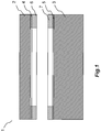
- Fig. 1:
- Komponenten eines keramischen Drucksensors, welche mittels des erfindungsgemäßen Verfahrens gefügt werden.
- Die in
Fig 1 dargestellten Komponenten eines keramischen Drucksensors 1 umfassen eine kreisscheibenförmige Messmembran 2 einen kreisscheibenförmigen Grundkörper 3 aus Korund. Insbesondere die Messmembran kann hochreines Korund mit einer Reinheit von besser als 99,98 % aufweisen. Die Messmembran 1 und der Grundkörper 2 weisen, je nach Ausgestaltung beispielsweise einen Durchmesser von etwa 15 bis 25 mm auf. Der Durchmesser ist jedoch keine erfindungswesentliche Größe und kann beispielsweise nach messtechnischen Erfordernissen oder anderen Randbedingungen gewählt werden. Die Messmembran 1 und der Grundkörper 2 sind mittels eines Zr-Ni-Ti-Aktivhartlots in einem Hochvakuumlötprozess druckdicht zu verbinden. - Hierzu werden die zu fügenden Stirnflächen der Messmembran 1 und des Grundkörpers 2 zunächst jeweils bis auf einen ringförmigen Randbereich maskiert, um dann das Aktivhartlot für die Fügestelle in dem ringförmigen Randbereich mittels Gasphasenabscheidung zu präparieren.
- Um die Reaktion mit dem jeweiligen Keramiksubstrat zu erleichtern, kann anstelle des unmittelbaren Abscheidens der Legierung mit einer Sollzusammensetzung zunächst ausschließlich eine aktive Komponente abgeschieden werden. Dies kann beispielsweise eine Titan-Schicht in einer Stärke von beispielsweise jeweils etwa 100 nm sein. Die Beschichtungen 4, 5 können beispielsweise in einem Sputterprozess mit einem reinen Ti-Target präpariert werden.
- Anschließend kann jeweils auf dem ringförmigen, mit der aktiven Komponente vorbeschichteten Bereich der Messmembran und des Grundkörpers ein Teil des für die Stärke der Fügestelle erforderlichen Aktivhartlots abgeschieden werden. Die Aufteilung kann beispielsweise hälftig sein, wonach bei einer angestrebten Stärke der Fügestelle von beispielsweise etwa 10 µm jeweils eine ringförmige Schicht 6, 7 mit einer Stärke von etwa 5 µm auf der Messmembran und auf dem Grundkörper in der Sollzusammensetzung abgeschieden werden kann. Hierzu wird ein Target eingesetzt, welches die Legierung des Aktivhartlots in der Sollzusammensetzung enthält. Das Target kann beispielsweise pulvermetallurgisch hergestellt sein.
- Um eine effiziente Abscheidungsrate mit hinreichend guter Kontrolle der Rate zu erzielen, wird bevorzugt eine Sputteranlage mit einem Hochleistungsmagnetron eingesetzt. Damit lassen sich kontrolliert Abscheidungsraten zwischen beispielsweise etwa 0,2 nm/s bis etwa 2 nm/s einstellen. Für das Abscheiden der 5 µm werden bei einer Abscheidungsrate von 2 mm/s dann 2500 s also knapp 42 Minuten benötigt.
- Nach dem vollständigen Abscheiden des Aktivhartlots zum Bilden der Fügestelle werden die Messmembran 2 und der Grundkörper 3 mit den Aktivhartlotringen aufeinandergelegt und in einem Vakuumlötprozess bei etwa 900 °C miteinander druckdicht verbunden.
- Vorzugsweise werden vor dem Abscheiden des Aktivhartlots (hier nicht dargestellte) Elektroden für einen kapazitiven Wandler des Drucksensors präpariert. Dies kann ebenfalls mittels Gasphasenabscheidung in einem Sputter-Verfahren erfolgen. Als Elektrodenmaterial ist beispielsweise Ta geeignet, welches in einer Stärke von beispielsweise 0,1 bis 0,2 µm abgeschieden wird. Eine bevorzugte Elektrodenanordnung kann beispielsweise eine Bildung eines Differentialkondensators ermöglichen, wozu auf der Stirnseite des Grundkörpers in dem von der ringförmigen Fügestelle zu umschließenden Bereich eine zentrale, kreisflächenförmige Messelektrode und eine diese umgebende, kapazitätsgleiche, ringförmige Referenzelektrode abgeschieden wird.
- Die Messelektrode, die Referenzelektrode und die Fügestelle sind beim fertigen Drucksensor vorzugsweise gegeneinander elektrisch isoliert.
- Auf der Membran wird vorzugsweise eine vollflächige Gegenelektrode präpariert, welche vorzugsweise beim fertigen Sensor mit der Fügestelle im galvanischen Kontakt steht.
Claims (8)
- Verfahren zum Herstellen einer Verbindung zwischen zwei Keramikteilen, umfassend:Bereitstellen eines ersten Keramikteils und eines zweiten Keramikteils;Bereitstellen eines Aktivhartlotmaterials auf zumindest einem Oberflächenabschnitt zumindest eines der Keramikteile; undErhitzen das Aktivhartlots in einem Vakuumlötprozess,wobei das gesamte Aktivhartlotmaterial zum Verbinden des ersten und des zweiten Keramikteils in der Weise bereitgestellt wird, dass zumindest ein Oberflächenabschnitt zumindest eines der Keramikteile, vorzugsweise beider Keramikteile, mittels einer Gasphasenabscheidung mit der Legierung des Aktivhartlots und/oder deren Komponenten beschichtet wird,wobei die Gasphasenabscheidung ein Sputterverfahren umfasst, um die Komponenten des Aktivhartlots in die Gasphase zu überführen,wobei das Aktivhartlot mehrere Komponenten aufweist, und wobei in dem Sputterverfahren ein Sputtertarget verwendet wird, welches die Komponenten des Aktivhartlots enthält,wobei das Aktivhartlot eine Sollzusammensetzung aufweist, in welcher Komponenten Ki des Aktivhartlots in einem Gewichtsprozentanteil ci vorliegen, und bei der die Differenz zwischen dem Wärmeausdehnungskoeffizienten des Aktivhartlots und dem Wärmeausdehnungskoeffizienten des Werkstoffs der Keramikteile, insbesondere bei gegebener Festigkeit der Fügestelle, ein Minimum aufweist, wobei das Sputtertarget die Komponenten des Aktivhartlots in Mengenverhältnissen ci, Target aufweist, die von der Sollzusammensetzung ci, Soll relative Abweichungen
 wobei die keramischen Teile Korund aufweisen,wobei das Aktivhartlot eine Zr-Ni-Ti-Legierung aufweist, undwobei die eine Aktive Komponente Ti oder Zr umfasst,dadurch gekennzeichnet, dassfür die Konzentrationen der Komponenten des Akitvhartlots in der Sollzusammensetzung gilt: 61 < cZr < 63,5, 21,5 < cNi < 24 und 14,5 < cTi <15,5.
 - Verfahren nach Anspruch 1, wobei der zumindest eine Oberflächenabschnitt des zumindest einen Keramikteils, mittels einer Gasphasenabscheidung zunächst nur mit einer aktiven Komponente des Aktivhartlots beschichtet wird.
- Verfahren nach Anspruch 2, wobei die Beschichtung mit der mindestens einen aktiven Komponente eine Stärke von nicht weniger als 10 nm, insbesondere nicht weniger als 40 nm, und bevorzugt nicht weniger als 80 nm aufweist.
- Verfahren nach Anspruch 2 oder 3, wobei die Beschichtung mit der mindestens einen aktiven Komponente eine Stärke von nicht mehr als 400 nm, insbesondere nicht mehr als 300 nm, und bevorzugt nicht mehr als 200 nm aufweist.
- Verfahren nach einem der Ansprüche 2 bis 4, wobei die eine aktive Komponente zur Gasphasenabscheidung mittels eines Sputter-Verfahrens in die Gasphase gebracht wird, und wobei in dem Sputterverfahren ein Sputtertarget verwendet wird, welches nur die eine aktive Komponente enthält.
- Verfahren nach einem der vorhergehenden Ansprüche, wobei der Lötprozess ein Vakuumlötprozess oder ein Lötprozess unter Schutzgas ist.
- Verfahren nach einem der vorhergehenden Ansprüche, wobei das erste Keramikteil und das zweite Keramikteil entlang einer ringförmigen Fügestelle, welche einen Hohlraum zwischen dem ersten Keramikteil und dem zweiten Keramikteil umschließt, druckdicht verbunden werden, wobei das Aktivhartlot auf mindestens einem ringförmigen Oberflächenabschnitt eines Keramikteils abgeschieden wird, wobei ein von dem ringförmigen Oberflächenabschnitt umschlossener Bereich während des Abscheidens des Aktivhartlots maskiert ist.
- Keramischer Drucksensor, welcher insbesondere nach einem Verfahren gemäß einem der Ansprüche 1 bis 7 erhältlich ist, wobei der Drucksensor ein erstes keramisches Teil und ein zweites keramisches Teil umfasst, und wobei das erste und das zweite keramische Teil mittels einer Fügestelle gefügt sind, die ein Aktivhartlot aufweist, wobei das Aktivhartlot in der Fügestelle eine Stärke von nicht mehr als 17 µm, bevorzugt nicht mehr als 14 µm und besonders bevorzugt nicht mehr als 12 µm aufweist, wobei die keramischen Teile Korund aufweisen, und wobei das Aktivhartlot eine Zr-Ni-Ti-Legierung umfasst, wobei das erste keramische Teil einen Grundkörper des Drucksensors umfasst, wobei das zweite keramische Teil die Messmembran des Drucksensors umfasst, und wobei die Messmembran mit dem Grundkörper entlang einer ringförmigen Fügestelle, welche das Aktivhartlot aufweist, druckdicht verbunden ist.
Applications Claiming Priority (2)
| Application Number | Priority Date | Filing Date | Title |
|---|---|---|---|
| DE201010043119 DE102010043119A1 (de) | 2010-10-29 | 2010-10-29 | Verfahren zum Herstellen einer Verbindung zwischen zwei Keramikteilen, insbesondere von Teilen eines Drucksensors, und ein keramisches Produkt, insbesondere einen keramischen Drucksensor |
| PCT/EP2011/068943 WO2012055989A1 (de) | 2010-10-29 | 2011-10-28 | Verfahren zum herstellen einer verbindung zwischen zwei keramikteilen, insbesondere von teilen eines drucksensors, und ein keramisches produkt, insbesondere einen keramischen drucksensor |
Publications (2)
| Publication Number | Publication Date |
|---|---|
| EP2632875A1 EP2632875A1 (de) | 2013-09-04 |
| EP2632875B1 true EP2632875B1 (de) | 2017-12-06 |
Family
ID=44913257
Family Applications (1)
| Application Number | Title | Priority Date | Filing Date |
|---|---|---|---|
| EP11779613.6A Not-in-force EP2632875B1 (de) | 2010-10-29 | 2011-10-28 | Verfahren zum herstellen einer verbindung zwischen zwei keramikteilen, insbesondere von teilen eines drucksensors und ein keramischer drucksensor |
Country Status (5)
| Country | Link |
|---|---|
| US (1) | US9136662B2 (de) |
| EP (1) | EP2632875B1 (de) |
| CN (1) | CN103189333A (de) |
| DE (1) | DE102010043119A1 (de) |
| WO (1) | WO2012055989A1 (de) |
Families Citing this family (19)
| Publication number | Priority date | Publication date | Assignee | Title |
|---|---|---|---|---|
| DE102010043119A1 (de) * | 2010-10-29 | 2012-05-03 | Endress + Hauser Gmbh + Co. Kg | Verfahren zum Herstellen einer Verbindung zwischen zwei Keramikteilen, insbesondere von Teilen eines Drucksensors, und ein keramisches Produkt, insbesondere einen keramischen Drucksensor |
| DE102010063065A1 (de) * | 2010-12-14 | 2012-06-14 | Endress + Hauser Gmbh + Co. Kg | Drucksensor und Verfahren zu dessen Herstellung+ |
| US9624137B2 (en) * | 2011-11-30 | 2017-04-18 | Component Re-Engineering Company, Inc. | Low temperature method for hermetically joining non-diffusing ceramic materials |
| DE102012103166B4 (de) | 2012-04-12 | 2025-02-06 | Endress+Hauser SE+Co. KG | Druckmesszelle und Verfahren zu ihrer Herstellung |
| DE102012110152A1 (de) * | 2012-07-11 | 2014-05-15 | Endress + Hauser Gmbh + Co. Kg | Verfahren zum Fügen von Keramikkörpern mittels eines Aktivhartlots, Baugruppe mit mindestens zwei miteinander gefügten Keramikkörpern, insbesondere Druckmesszelle |
| DE102012106236A1 (de) * | 2012-07-11 | 2014-01-16 | Endress + Hauser Gmbh + Co. Kg | Verfahren zum Fügen von Keramikkörpern mittels eines Aktivhartlots, Baugruppe mit mindestens zwei miteinander gefügten Keramikkörpern, insbesondere Druckmesszelle |
| DE102012110618A1 (de) * | 2012-11-06 | 2014-05-22 | Endress + Hauser Gmbh + Co. Kg | Baugruppe mit mindestens zwei miteinander gefügten Keramikkörpern, insbesondere Druckmesszelle, und Verfahren zum Fügen von Keramikkörpern mittels eines Aktivhartlots |
| DE102013105132A1 (de) * | 2013-05-17 | 2014-11-20 | Endress + Hauser Gmbh + Co. Kg | Keramische Druckmesszelle und Verfahren zu ihrer Herstellung |
| DE102013106045A1 (de) | 2013-06-11 | 2014-12-11 | Endress + Hauser Gmbh + Co. Kg | Kapazitive, keramische Druckmesszelle und Verfahren zu ihrer Herstellung |
| US9863830B2 (en) * | 2014-04-23 | 2018-01-09 | Endress + Hauser Gmbh + Co. Kg | Pressure sensor having a ceramic platform |
| DE102014109842A1 (de) | 2014-07-14 | 2016-01-14 | Endress + Hauser Gmbh + Co. Kg | Keramischer Drucksensor mit einer Aktivhartlötung und Verfahren zur Aktivhartlötung zweier Bauteile |
| DE102014113958A1 (de) | 2014-09-26 | 2016-03-31 | Endress + Hauser Gmbh + Co. Kg | Verfahren zum Herstellen einer Verbindung zwischen zwei Keramikteilen, insbesondere von Teilen eines Drucksensors |
| DE102014115801A1 (de) | 2014-10-30 | 2016-05-04 | Endress + Hauser Gmbh + Co. Kg | Keramischer Drucksensor und Verfahren zu dessen Herstellung |
| DE102014116761A1 (de) | 2014-11-17 | 2016-05-19 | Endress + Hauser Gmbh + Co. Kg | Verfahren zum Herstellen einer Verbindung zwischen zwei Keramikteilen, insbesondere von Teilen eines Drucksensors |
| DE102014118430A1 (de) | 2014-12-11 | 2016-06-16 | Endress + Hauser Gmbh + Co. Kg | Aktivhartlotmaterial und Verfahren zur Aktivhartlötung von Bauteilen |
| DE102015105057A1 (de) | 2015-04-01 | 2016-10-06 | Endress + Hauser Gmbh + Co. Kg | Kapazitiver Drucksensor |
| DE102015108950A1 (de) * | 2015-06-08 | 2016-12-08 | Endress + Hauser Gmbh + Co. Kg | Drucksensor mit einer Aktivhartlötung |
| DE102015108949A1 (de) | 2015-06-08 | 2016-12-08 | Endress + Hauser Gmbh + Co. Kg | Aktivhartlot zum Aktivhartlöten von Keramik |
| DE102016102775A1 (de) | 2016-02-17 | 2017-08-17 | Endress+Hauser Gmbh+Co. Kg | Kapazitiver Drucksensor |
Family Cites Families (21)
| Publication number | Priority date | Publication date | Assignee | Title |
|---|---|---|---|---|
| DE3602104A1 (de) * | 1986-01-24 | 1987-07-30 | Glyco Metall Werke | Gleit- oder reibelement mit funktionsteil aus keramischem werkstoff sowie verfahren zu seiner herstellung |
| DE3602132A1 (de) * | 1986-01-24 | 1987-07-30 | Glyco Metall Werke | Gleit- oder reibelement mit funktionsteil aus keramischem werkstoff mit eingelagertem stabilisator sowie verfahren zu seiner herstellung |
| DE3888380T2 (de) * | 1987-04-02 | 1994-10-13 | Toshiba Kawasaki Kk | Luftdichter Keramikbehälter. |
| DE4129414A1 (de) | 1990-11-13 | 1993-03-11 | Endress Hauser Gmbh Co | Verwendung eines speziellen tiegels beim melt-spinning einer aktivlot-legierung |
| EP0558874B1 (de) | 1992-03-05 | 1995-05-24 | Endress + Hauser Gmbh + Co. | Verfahren und Vorrichtung zum Herstellen von Ringen aus einer Aktivhartlot-Legierung |
| FR2751640B1 (fr) | 1996-07-23 | 1998-08-28 | Commissariat Energie Atomique | Composition et procede de brasage reactif de materiaux ceramiques contenant de l'alumine |
| US6039918A (en) * | 1996-07-25 | 2000-03-21 | Endress + Hauser Gmbh + Co. | Active brazing solder for brazing alumina-ceramic parts |
| US20040099061A1 (en) * | 1997-12-22 | 2004-05-27 | Mks Instruments | Pressure sensor for detecting small pressure differences and low pressures |
| EP0988919B1 (de) | 1998-09-22 | 2003-10-29 | Endress + Hauser GmbH + Co. KG | Siebdruck- oder dispensierfähige Aktivhartlotpasten und Verfahren zu deren Herstellung |
| US6156130A (en) * | 1998-09-22 | 2000-12-05 | Endress Hauser Gmbh Co | Screen-printable or dispensable active brazing pastes and process for producing the same |
| FR2787737B1 (fr) * | 1998-12-23 | 2001-01-19 | Commissariat Energie Atomique | Composition de brasure, procede d'assemblage de pieces en materiaux a base d'alumine par brasage refractaire avec ladite composition de brasure, assemblage et joint refractaire ainsi obtenus |
| US6528123B1 (en) * | 2000-06-28 | 2003-03-04 | Sandia Corporation | Coating system to permit direct brazing of ceramics |
| US7137301B2 (en) * | 2004-10-07 | 2006-11-21 | Mks Instruments, Inc. | Method and apparatus for forming a reference pressure within a chamber of a capacitance sensor |
| US7141447B2 (en) * | 2004-10-07 | 2006-11-28 | Mks Instruments, Inc. | Method of forming a seal between a housing and a diaphragm of a capacitance sensor |
| DE112007002372B4 (de) * | 2006-11-13 | 2017-04-06 | Inficon Gmbh | Vakuummembranmesszelle und Verfahren zur Herstellung einer derartigen Messzelle |
| DE102007026243A1 (de) * | 2007-06-04 | 2008-12-11 | Endress + Hauser Gmbh + Co. Kg | Kapazitiver Drucksensor |
| US7814798B2 (en) * | 2008-09-17 | 2010-10-19 | P I Components Corporation | Diaphragm structure and method of manufacturing a diaphragm structure |
| DE102009003178A1 (de) * | 2009-05-18 | 2010-11-25 | Endress + Hauser Gmbh + Co. Kg | Keramisches Bauteil mit mindestens einer elektrischen Durchführung, Verfahren zu dessen Herstellung und Drucksensor mit einem solchen Bauteil |
| DE102009054909A1 (de) | 2009-12-17 | 2011-06-22 | Endress + Hauser GmbH + Co. KG, 79689 | Keramisches Produkt und Verfahren zu dessen Herstellung |
| DE102010043119A1 (de) * | 2010-10-29 | 2012-05-03 | Endress + Hauser Gmbh + Co. Kg | Verfahren zum Herstellen einer Verbindung zwischen zwei Keramikteilen, insbesondere von Teilen eines Drucksensors, und ein keramisches Produkt, insbesondere einen keramischen Drucksensor |
| DE102010063065A1 (de) * | 2010-12-14 | 2012-06-14 | Endress + Hauser Gmbh + Co. Kg | Drucksensor und Verfahren zu dessen Herstellung+ |
-
2010
- 2010-10-29 DE DE201010043119 patent/DE102010043119A1/de not_active Withdrawn
-
2011
- 2011-10-28 WO PCT/EP2011/068943 patent/WO2012055989A1/de not_active Ceased
- 2011-10-28 CN CN2011800529039A patent/CN103189333A/zh active Pending
- 2011-10-28 EP EP11779613.6A patent/EP2632875B1/de not_active Not-in-force
- 2011-10-28 US US13/881,533 patent/US9136662B2/en not_active Expired - Fee Related
Also Published As
| Publication number | Publication date |
|---|---|
| DE102010043119A1 (de) | 2012-05-03 |
| US9136662B2 (en) | 2015-09-15 |
| CN103189333A (zh) | 2013-07-03 |
| US20130213138A1 (en) | 2013-08-22 |
| EP2632875A1 (de) | 2013-09-04 |
| WO2012055989A1 (de) | 2012-05-03 |
Similar Documents
| Publication | Publication Date | Title |
|---|---|---|
| DE102010043119A1 (de) | Verfahren zum Herstellen einer Verbindung zwischen zwei Keramikteilen, insbesondere von Teilen eines Drucksensors, und ein keramisches Produkt, insbesondere einen keramischen Drucksensor | |
| EP2652472B1 (de) | Drucksensor und verfahren zu dessen herstellung | |
| EP2162714B1 (de) | Kapazitiver drucksensor | |
| EP0123702B1 (de) | Verfahren zum Verbinden von metallischen Bauelementen | |
| DE3781882T2 (de) | Zwischenstueck zum diffusionsfuegen mit fluessiger phase. | |
| EP2513622B1 (de) | Keramisches produkt und verfahren zu dessen herstellung | |
| EP2872279B1 (de) | Verfahren zum fügen von keramikkörpern mittels eines aktivhartlots unter verwendung eines lotstopps, baugruppe mit mindestens zwei miteinander gefügten keramikkörpern, insbesondere druckmesszelle | |
| DE2657083A1 (de) | Verbund-zwischenschicht fuer das diffusionsbinden | |
| EP0001220A1 (de) | Verfahren zum mittelbaren Verbinden zweier Teile | |
| EP2872280B1 (de) | Baugruppe mit mindestens zwei miteinander gefügten keramikkörpern, insbesondere druckmesszelle ; verfahren zum herstellen einer solchen baugruppe | |
| WO2009003826A1 (de) | Drucksensor | |
| EP2917165A1 (de) | Baugruppe mit zwei miteinander gefügten keramikkörpern, insbesondere druckmesszelle, und verfahren zum fügen von keramikkörpern mittels eines aktivhartlots | |
| WO2014183960A1 (de) | Keramische druckmesszelle und verfahren zu ihrer herstellung | |
| DE102016112200A1 (de) | Druckaufnehmer | |
| DE69413327T2 (de) | Mosaik-Zerstäubungs-Target | |
| EP4076833A1 (de) | Fügen von zwei bauteilen eines feldgeräts der prozess- und automatisierungstechnik | |
| DE102014118430A1 (de) | Aktivhartlotmaterial und Verfahren zur Aktivhartlötung von Bauteilen | |
| EP3304019A1 (de) | Drucksensor mit einer aktivhartlötung | |
| DE102016112198A1 (de) | Druckaufnehmer | |
| EP0988919B1 (de) | Siebdruck- oder dispensierfähige Aktivhartlotpasten und Verfahren zu deren Herstellung | |
| EP3197848B1 (de) | Verfahren zum herstellen einer verbindung zwischen zwei keramikteilen, insbesondere von teilen eines drucksensors | |
| AT18142U1 (de) | Siliziumhaltige übergangsmetallboridverdampfungsquelle | |
| DE102014116761A1 (de) | Verfahren zum Herstellen einer Verbindung zwischen zwei Keramikteilen, insbesondere von Teilen eines Drucksensors | |
| WO2002077596A1 (de) | Verfahren zur herstellung eines korrosionsbeständigen trennkörpers | |
| WO2022048900A1 (de) | Drucksensor und verfahren zur herstellung eines drucksensors |
Legal Events
| Date | Code | Title | Description |
|---|---|---|---|
| PUAI | Public reference made under article 153(3) epc to a published international application that has entered the european phase |
Free format text: ORIGINAL CODE: 0009012 |
|
| 17P | Request for examination filed |
Effective date: 20130404 |
|
| AK | Designated contracting states |
Kind code of ref document: A1 Designated state(s): AL AT BE BG CH CY CZ DE DK EE ES FI FR GB GR HR HU IE IS IT LI LT LU LV MC MK MT NL NO PL PT RO RS SE SI SK SM TR |
|
| DAX | Request for extension of the european patent (deleted) | ||
| 17Q | First examination report despatched |
Effective date: 20150929 |
|
| GRAP | Despatch of communication of intention to grant a patent |
Free format text: ORIGINAL CODE: EPIDOSNIGR1 |
|
| RIC1 | Information provided on ipc code assigned before grant |
Ipc: B23K 1/19 20060101ALI20170623BHEP Ipc: G01L 9/00 20060101ALN20170623BHEP Ipc: B23K 1/00 20060101ALI20170623BHEP Ipc: B23K 35/02 20060101ALI20170623BHEP Ipc: B23K 35/32 20060101ALI20170623BHEP Ipc: B23K 1/008 20060101ALI20170623BHEP Ipc: C04B 37/00 20060101AFI20170623BHEP |
|
| INTG | Intention to grant announced |
Effective date: 20170712 |
|
| GRAS | Grant fee paid |
Free format text: ORIGINAL CODE: EPIDOSNIGR3 |
|
| GRAA | (expected) grant |
Free format text: ORIGINAL CODE: 0009210 |
|
| AK | Designated contracting states |
Kind code of ref document: B1 Designated state(s): AL AT BE BG CH CY CZ DE DK EE ES FI FR GB GR HR HU IE IS IT LI LT LU LV MC MK MT NL NO PL PT RO RS SE SI SK SM TR |
|
| REG | Reference to a national code |
Ref country code: GB Ref legal event code: FG4D Free format text: NOT ENGLISH |
|
| REG | Reference to a national code |
Ref country code: AT Ref legal event code: REF Ref document number: 952220 Country of ref document: AT Kind code of ref document: T Effective date: 20171215 Ref country code: CH Ref legal event code: EP |
|
| REG | Reference to a national code |
Ref country code: IE Ref legal event code: FG4D Free format text: LANGUAGE OF EP DOCUMENT: GERMAN |
|
| REG | Reference to a national code |
Ref country code: DE Ref legal event code: R096 Ref document number: 502011013418 Country of ref document: DE |
|
| REG | Reference to a national code |
Ref country code: DE Ref legal event code: R081 Ref document number: 502011013418 Country of ref document: DE Owner name: ENDRESS+HAUSER SE+CO. KG, DE Free format text: FORMER OWNER: ENDRESS + HAUSER GMBH + CO. KG, 79689 MAULBURG, DE |
|
| RAP2 | Party data changed (patent owner data changed or rights of a patent transferred) |
Owner name: ENDRESS+HAUSER SE+CO. KG |
|
| REG | Reference to a national code |
Ref country code: NL Ref legal event code: MP Effective date: 20171206 |
|
| REG | Reference to a national code |
Ref country code: LT Ref legal event code: MG4D |
|
| PG25 | Lapsed in a contracting state [announced via postgrant information from national office to epo] |
Ref country code: SE Free format text: LAPSE BECAUSE OF FAILURE TO SUBMIT A TRANSLATION OF THE DESCRIPTION OR TO PAY THE FEE WITHIN THE PRESCRIBED TIME-LIMIT Effective date: 20171206 Ref country code: LT Free format text: LAPSE BECAUSE OF FAILURE TO SUBMIT A TRANSLATION OF THE DESCRIPTION OR TO PAY THE FEE WITHIN THE PRESCRIBED TIME-LIMIT Effective date: 20171206 Ref country code: FI Free format text: LAPSE BECAUSE OF FAILURE TO SUBMIT A TRANSLATION OF THE DESCRIPTION OR TO PAY THE FEE WITHIN THE PRESCRIBED TIME-LIMIT Effective date: 20171206 Ref country code: NO Free format text: LAPSE BECAUSE OF FAILURE TO SUBMIT A TRANSLATION OF THE DESCRIPTION OR TO PAY THE FEE WITHIN THE PRESCRIBED TIME-LIMIT Effective date: 20180306 Ref country code: ES Free format text: LAPSE BECAUSE OF FAILURE TO SUBMIT A TRANSLATION OF THE DESCRIPTION OR TO PAY THE FEE WITHIN THE PRESCRIBED TIME-LIMIT Effective date: 20171206 |
|
| PG25 | Lapsed in a contracting state [announced via postgrant information from national office to epo] |
Ref country code: HR Free format text: LAPSE BECAUSE OF FAILURE TO SUBMIT A TRANSLATION OF THE DESCRIPTION OR TO PAY THE FEE WITHIN THE PRESCRIBED TIME-LIMIT Effective date: 20171206 Ref country code: GR Free format text: LAPSE BECAUSE OF FAILURE TO SUBMIT A TRANSLATION OF THE DESCRIPTION OR TO PAY THE FEE WITHIN THE PRESCRIBED TIME-LIMIT Effective date: 20180307 Ref country code: BG Free format text: LAPSE BECAUSE OF FAILURE TO SUBMIT A TRANSLATION OF THE DESCRIPTION OR TO PAY THE FEE WITHIN THE PRESCRIBED TIME-LIMIT Effective date: 20180306 Ref country code: LV Free format text: LAPSE BECAUSE OF FAILURE TO SUBMIT A TRANSLATION OF THE DESCRIPTION OR TO PAY THE FEE WITHIN THE PRESCRIBED TIME-LIMIT Effective date: 20171206 Ref country code: RS Free format text: LAPSE BECAUSE OF FAILURE TO SUBMIT A TRANSLATION OF THE DESCRIPTION OR TO PAY THE FEE WITHIN THE PRESCRIBED TIME-LIMIT Effective date: 20171206 |
|
| PG25 | Lapsed in a contracting state [announced via postgrant information from national office to epo] |
Ref country code: NL Free format text: LAPSE BECAUSE OF FAILURE TO SUBMIT A TRANSLATION OF THE DESCRIPTION OR TO PAY THE FEE WITHIN THE PRESCRIBED TIME-LIMIT Effective date: 20171206 |
|
| PG25 | Lapsed in a contracting state [announced via postgrant information from national office to epo] |
Ref country code: EE Free format text: LAPSE BECAUSE OF FAILURE TO SUBMIT A TRANSLATION OF THE DESCRIPTION OR TO PAY THE FEE WITHIN THE PRESCRIBED TIME-LIMIT Effective date: 20171206 Ref country code: SK Free format text: LAPSE BECAUSE OF FAILURE TO SUBMIT A TRANSLATION OF THE DESCRIPTION OR TO PAY THE FEE WITHIN THE PRESCRIBED TIME-LIMIT Effective date: 20171206 Ref country code: CZ Free format text: LAPSE BECAUSE OF FAILURE TO SUBMIT A TRANSLATION OF THE DESCRIPTION OR TO PAY THE FEE WITHIN THE PRESCRIBED TIME-LIMIT Effective date: 20171206 |
|
| PG25 | Lapsed in a contracting state [announced via postgrant information from national office to epo] |
Ref country code: IT Free format text: LAPSE BECAUSE OF FAILURE TO SUBMIT A TRANSLATION OF THE DESCRIPTION OR TO PAY THE FEE WITHIN THE PRESCRIBED TIME-LIMIT Effective date: 20171206 Ref country code: SM Free format text: LAPSE BECAUSE OF FAILURE TO SUBMIT A TRANSLATION OF THE DESCRIPTION OR TO PAY THE FEE WITHIN THE PRESCRIBED TIME-LIMIT Effective date: 20171206 Ref country code: RO Free format text: LAPSE BECAUSE OF FAILURE TO SUBMIT A TRANSLATION OF THE DESCRIPTION OR TO PAY THE FEE WITHIN THE PRESCRIBED TIME-LIMIT Effective date: 20171206 Ref country code: PL Free format text: LAPSE BECAUSE OF FAILURE TO SUBMIT A TRANSLATION OF THE DESCRIPTION OR TO PAY THE FEE WITHIN THE PRESCRIBED TIME-LIMIT Effective date: 20171206 |
|
| REG | Reference to a national code |
Ref country code: DE Ref legal event code: R097 Ref document number: 502011013418 Country of ref document: DE |
|
| PG25 | Lapsed in a contracting state [announced via postgrant information from national office to epo] |
Ref country code: MT Free format text: LAPSE BECAUSE OF FAILURE TO SUBMIT A TRANSLATION OF THE DESCRIPTION OR TO PAY THE FEE WITHIN THE PRESCRIBED TIME-LIMIT Effective date: 20171206 |
|
| PLBE | No opposition filed within time limit |
Free format text: ORIGINAL CODE: 0009261 |
|
| STAA | Information on the status of an ep patent application or granted ep patent |
Free format text: STATUS: NO OPPOSITION FILED WITHIN TIME LIMIT |
|
| 26N | No opposition filed |
Effective date: 20180907 |
|
| PG25 | Lapsed in a contracting state [announced via postgrant information from national office to epo] |
Ref country code: DK Free format text: LAPSE BECAUSE OF FAILURE TO SUBMIT A TRANSLATION OF THE DESCRIPTION OR TO PAY THE FEE WITHIN THE PRESCRIBED TIME-LIMIT Effective date: 20171206 Ref country code: SI Free format text: LAPSE BECAUSE OF FAILURE TO SUBMIT A TRANSLATION OF THE DESCRIPTION OR TO PAY THE FEE WITHIN THE PRESCRIBED TIME-LIMIT Effective date: 20171206 |
|
| REG | Reference to a national code |
Ref country code: CH Ref legal event code: PL |
|
| GBPC | Gb: european patent ceased through non-payment of renewal fee |
Effective date: 20181028 |
|
| REG | Reference to a national code |
Ref country code: BE Ref legal event code: MM Effective date: 20181031 |
|
| PG25 | Lapsed in a contracting state [announced via postgrant information from national office to epo] |
Ref country code: MC Free format text: LAPSE BECAUSE OF FAILURE TO SUBMIT A TRANSLATION OF THE DESCRIPTION OR TO PAY THE FEE WITHIN THE PRESCRIBED TIME-LIMIT Effective date: 20171206 Ref country code: LU Free format text: LAPSE BECAUSE OF NON-PAYMENT OF DUE FEES Effective date: 20181028 |
|
| REG | Reference to a national code |
Ref country code: IE Ref legal event code: MM4A |
|
| PG25 | Lapsed in a contracting state [announced via postgrant information from national office to epo] |
Ref country code: LI Free format text: LAPSE BECAUSE OF NON-PAYMENT OF DUE FEES Effective date: 20181031 Ref country code: CH Free format text: LAPSE BECAUSE OF NON-PAYMENT OF DUE FEES Effective date: 20181031 Ref country code: BE Free format text: LAPSE BECAUSE OF NON-PAYMENT OF DUE FEES Effective date: 20181031 |
|
| PG25 | Lapsed in a contracting state [announced via postgrant information from national office to epo] |
Ref country code: IE Free format text: LAPSE BECAUSE OF NON-PAYMENT OF DUE FEES Effective date: 20181028 Ref country code: GB Free format text: LAPSE BECAUSE OF NON-PAYMENT OF DUE FEES Effective date: 20181028 Ref country code: FR Free format text: LAPSE BECAUSE OF NON-PAYMENT OF DUE FEES Effective date: 20181031 |
|
| REG | Reference to a national code |
Ref country code: AT Ref legal event code: MM01 Ref document number: 952220 Country of ref document: AT Kind code of ref document: T Effective date: 20181028 |
|
| PG25 | Lapsed in a contracting state [announced via postgrant information from national office to epo] |
Ref country code: AT Free format text: LAPSE BECAUSE OF NON-PAYMENT OF DUE FEES Effective date: 20181028 |
|
| PG25 | Lapsed in a contracting state [announced via postgrant information from national office to epo] |
Ref country code: TR Free format text: LAPSE BECAUSE OF FAILURE TO SUBMIT A TRANSLATION OF THE DESCRIPTION OR TO PAY THE FEE WITHIN THE PRESCRIBED TIME-LIMIT Effective date: 20171206 |
|
| PG25 | Lapsed in a contracting state [announced via postgrant information from national office to epo] |
Ref country code: PT Free format text: LAPSE BECAUSE OF FAILURE TO SUBMIT A TRANSLATION OF THE DESCRIPTION OR TO PAY THE FEE WITHIN THE PRESCRIBED TIME-LIMIT Effective date: 20171206 |
|
| PG25 | Lapsed in a contracting state [announced via postgrant information from national office to epo] |
Ref country code: HU Free format text: LAPSE BECAUSE OF FAILURE TO SUBMIT A TRANSLATION OF THE DESCRIPTION OR TO PAY THE FEE WITHIN THE PRESCRIBED TIME-LIMIT; INVALID AB INITIO Effective date: 20111028 Ref country code: MK Free format text: LAPSE BECAUSE OF NON-PAYMENT OF DUE FEES Effective date: 20171206 Ref country code: CY Free format text: LAPSE BECAUSE OF FAILURE TO SUBMIT A TRANSLATION OF THE DESCRIPTION OR TO PAY THE FEE WITHIN THE PRESCRIBED TIME-LIMIT Effective date: 20171206 |
|
| PG25 | Lapsed in a contracting state [announced via postgrant information from national office to epo] |
Ref country code: AL Free format text: LAPSE BECAUSE OF FAILURE TO SUBMIT A TRANSLATION OF THE DESCRIPTION OR TO PAY THE FEE WITHIN THE PRESCRIBED TIME-LIMIT Effective date: 20171206 Ref country code: IS Free format text: LAPSE BECAUSE OF FAILURE TO SUBMIT A TRANSLATION OF THE DESCRIPTION OR TO PAY THE FEE WITHIN THE PRESCRIBED TIME-LIMIT Effective date: 20180406 |
|
| P01 | Opt-out of the competence of the unified patent court (upc) registered |
Effective date: 20230601 |
|
| PGFP | Annual fee paid to national office [announced via postgrant information from national office to epo] |
Ref country code: DE Payment date: 20231020 Year of fee payment: 13 |
|
| REG | Reference to a national code |
Ref country code: DE Ref legal event code: R119 Ref document number: 502011013418 Country of ref document: DE |
|
| PG25 | Lapsed in a contracting state [announced via postgrant information from national office to epo] |
Ref country code: DE Free format text: LAPSE BECAUSE OF NON-PAYMENT OF DUE FEES Effective date: 20250501 |