EP2632612B1 - Superhydrophobic films - Google Patents
Superhydrophobic films Download PDFInfo
- Publication number
- EP2632612B1 EP2632612B1 EP11782275.9A EP11782275A EP2632612B1 EP 2632612 B1 EP2632612 B1 EP 2632612B1 EP 11782275 A EP11782275 A EP 11782275A EP 2632612 B1 EP2632612 B1 EP 2632612B1
- Authority
- EP
- European Patent Office
- Prior art keywords
- film
- major surface
- superhydrophobic
- portions
- microstructures
- Prior art date
- Legal status (The legal status is an assumption and is not a legal conclusion. Google has not performed a legal analysis and makes no representation as to the accuracy of the status listed.)
- Not-in-force
Links
Images


Classifications
-
- B—PERFORMING OPERATIONS; TRANSPORTING
- B08—CLEANING
- B08B—CLEANING IN GENERAL; PREVENTION OF FOULING IN GENERAL
- B08B17/00—Methods preventing fouling
- B08B17/02—Preventing deposition of fouling or of dust
- B08B17/06—Preventing deposition of fouling or of dust by giving articles subject to fouling a special shape or arrangement
- B08B17/065—Preventing deposition of fouling or of dust by giving articles subject to fouling a special shape or arrangement the surface having a microscopic surface pattern to achieve the same effect as a lotus flower
-
- B—PERFORMING OPERATIONS; TRANSPORTING
- B08—CLEANING
- B08B—CLEANING IN GENERAL; PREVENTION OF FOULING IN GENERAL
- B08B17/00—Methods preventing fouling
- B08B17/02—Preventing deposition of fouling or of dust
- B08B17/06—Preventing deposition of fouling or of dust by giving articles subject to fouling a special shape or arrangement
-
- Y—GENERAL TAGGING OF NEW TECHNOLOGICAL DEVELOPMENTS; GENERAL TAGGING OF CROSS-SECTIONAL TECHNOLOGIES SPANNING OVER SEVERAL SECTIONS OF THE IPC; TECHNICAL SUBJECTS COVERED BY FORMER USPC CROSS-REFERENCE ART COLLECTIONS [XRACs] AND DIGESTS
- Y10—TECHNICAL SUBJECTS COVERED BY FORMER USPC
- Y10T—TECHNICAL SUBJECTS COVERED BY FORMER US CLASSIFICATION
- Y10T428/00—Stock material or miscellaneous articles
- Y10T428/24—Structurally defined web or sheet [e.g., overall dimension, etc.]
- Y10T428/24355—Continuous and nonuniform or irregular surface on layer or component [e.g., roofing, etc.]
- Y10T428/24372—Particulate matter
- Y10T428/24405—Polymer or resin [e.g., natural or synthetic rubber, etc.]
Definitions
- the present description relates to superhydrophobic films and methods of making such films. More particularly, the present description relates to durable superhydrophobic films having a surface with discrete flat portions and valleys and different methods of producing such films.
- Hydrophobic films and coatings and more particularly, superhydrophobic films and coatings have garnered considerable attention in recent years due to a number of attractive qualities.
- Highly hydrophobic surfaces have been recognized in nature, perhaps most prevalently on lotus leaves and also on cicada wings. Because of its hydrophobic properties, the lotus leaf is capable of self-cleaning by the washing away of dust particles and debris as water droplets roll off its surface. This ability to self-clean is desirable in a number of modern-day applications.
- the current description provides a superhydrophobic film that has a surface that is highly durable and weatherable in variable conditions, for example, outdoors, and performs very effectively without serious performance concerns after abrasive exposure.
- US 2010/028604 A1 discloses hierarchical structures for superhydrophobic surfaces and methods of making the same.
- the present description relates to a superhydrophobic film having a first major surface and a second major surface opposite the first major surface.
- the second major surface of the film has an array of prisms, wherein at least some of the prisms comprise discrete flat surface portions substantially parallel to the first major surface, and also has an array of valleys, where at least one valley is positioned between adjacent prisms of the array of prisms.
- Each of the discrete flat surface portions and valleys has a plurality of nanofeatures, and the superhydrophobic film exhibits a water contact angle of at least 140 degrees and a sliding angle of less than 10 degrees.
- the present description relates to a superhydrophobic film having a first major surface, a second major surface, and a low surface energy coating.
- the second major surface of the film has an array of prisms, wherein at least some of the prisms comprise discrete flat surface portions substantially parallel to the first major surface, and also has an array of valleys, where at least one valley is positioned between adjacent prisms of the array of prisms.
- the low surface energy coating is applied to the array of discrete flat surface portions and array of valleys, and comprises nanoparticles.
- the superhydrophobic film exhibits a water contact angle of at least 140 degrees and a sliding angle of less than 10 degrees.
- the present description relates to one more method of producing a superhydrophobic film.
- the method includes a step of providing a structured film that has a first major surface and a second major surface opposite the first major surface.
- the second major surface may include a plurality of microstructures, where at least some of the microstructures have a discrete flat surface portion on the top of the microstructure, the discrete flat surface portions being substantially parallel to the first major surface.
- the method further includes applying a fluorochemical coating to the second major surface.
- the fluorochemical coating includes a plurality of nanoparticles.
- the film may be provided by replication from a mold having valleys with at least some flat bases.
- the present description relates to a method of producing a superhydrophobic film.
- the method includes a step of providing a structured film that has a first major surface and a second major surface opposite the first major surface.
- the second major surface may include a plurality of microstructures, where at least some of the microstructures have a discrete flat surface portion on the top of the microstructure, the discrete flat surface portions being substantially parallel to the first major surface.
- the method further includes the step of applying a layer of nanoparticles to the second major surface.
- the second major surface is etched using the layer of nanoparticles as an etch mask. The result is a plurality of nanostructures on the discrete flat surface portions and remainder of the microstructures.
- Superhydrophobic films and surfaces are very desirable in a number of applications due to their ability to self-clean.
- a film may be considered "superhydrophobic" where the water contact angle is greater than 140 degrees.
- Superhydrophobic films may further be understood as generally nonwettable, as water beads off of the surface of the film upon contact.
- a further desirable quality for such films may be low contact angle hysteresis, that is, a small difference between the advancing and receding contact angles of the water droplet.
- a low contact angle hysteresis, or “sliding angle” allows for water beads to roll off of the surface of a film or other construction more easily. The combination of the ability to bead water that comes into contact with the surface of a structure and further roll the beaded water off of the surface is what makes the surface "self-cleaning.”
- self-cleaning superhydrophobic surfaces may be useful on the sun-facing surfaces of solar (photovoltaic) cells, in anti-icing applications, corrosion prevention, anti-condensation applications, wind blades, traffic signals, edge seals, anti-fouling applications, and drag reduction and/or noise reduction for automobiles, aircraft, boats and microfluidic devices, just to name a few.
- Such films may also have valuable anti-reflection properties.
- the currently described films may exhibit very low reflectivity and therefore be highly transmissive. This is a highly beneficial property for applications where films are applied to solar cells, or any sort of window or light transmissive usage where the films are used for self-cleaning or anti-icing properties.
- the films described herein may reflect less than 5% of incident light, and may reflect less than 2% of incident light. In some application, only approximately 1% of light incident on the films is reflected.
- a number of superhydrophobic films may derive their superhydrophobic properties from the fact that they have microstructures or microparticles that are overlaid with nanostructures or nanoparticles.
- a great deal of difficulty arises, however, in preserving the nanoparticles or nanostructures on or near the peaks of the microstructures of the film as they degrade over time.
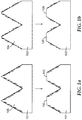
- An example of this effect is illustrated in Fig. 1 .
- nanostructures or nanocavities are formed into the microstructures 103 and 104.
- the peaks of the microstructures 103 may be worn away as illustrated in the flow chart.
- the result is a flat portion 110 or 120 that is barren of any nanocavities and/or nanofeatures (or particles, as the case may be), and will suffer a lower degree of hydrophobicity.
- the present description aims to provide a solution to these issues, and further provide a superhydrophobic film that is highly durable.
- the present description aims to preempt the wearing away of microstructures, and consequently, nanofeatures in or on those microstructures, or nanoparticles on those microstructures.
- the present description provides for a microstructured film where at least some of the microstructures are truncated to provide a flat surface. This allows for a distribution of external forces (e.g. abrasion) over a larger area of the surface of the microstructures, resulting in a smaller force per area, such that the height of microstructures may be maintained, and the nanoparticles and nanofeatures may be preserved at greater length, providing for greater performance.
- superhydrophobic film 200 has a first major surface 202.
- the first major surface 202 may be flat as illustrated in the figure. In other embodiments, the surface may have slight matte variation or microstructures, but in such cases, the film may generally be understood as having an average height that lies in a flat plane.
- the superhydrophobic film 200 also has a second major surface 204 that is opposite the first major surface 202.
- the second major surface may be understood as being made up of at least two different sub-parts.
- the first subpart of the second major surface is an array of discrete flat surface portions 206. Each of the discrete flat surface portions 206 is substantially parallel to the first major surface 202.
- the first major surface 202 will be flat. However, where there is slight variation in the surface, the flat discrete portions will lie parallel to the flat plane that is the average height of first major surface 202.
- the second subpart of second major surface 204 is an array of valleys 208.
- Each valley 208 in the array of valleys is positioned between adjacent discrete flat surface portions 206.
- the valleys 208 are shown as having facets that terminate at a common point 207.
- valleys are also contemplated that have flat or near-flat bottoms of the valley, as well as side facets of microstructures that have sudden discontinuities in slope.
- the valleys may have side walls 212 that are flat, as shown in Fig. 2 .
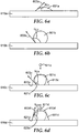
- the side walls 212 may be curved, such as in a portion of a microlens. Examples of just a few different shapes that valleys may take according to the present description are illustrated in Figs.
- the valley may have flat side walls as illustrated in Fig. 5a , or may have curved sidewalls that are concave down, such as shown in Fig. 5b .
- the side walls may also be curved and concave up, as illustrated in Fig. 5c .
- a number of other valley shapes are also contemplated.
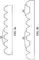
- the discrete flat portions 206 may be spaced apart in a constant periodic manner, as shown in Fig. 3a , or may be variably spaced apart at different distances along the second major surface, as illustrated by flat portions 206 in Fig. 3b .
- the structured film will be made up of microstructures 1102, and that portion below the microstructures that is a solid portion of the film that connects and stabilizes the film without varying structure. This portion may be understood as "land" 1104.
- the land generally should be of a sufficient thickness to generate stability for the entire film.
- the land for example may have a thickness 1150 than is at least greater than 25 microns, and often greater than 100 microns.
- the microstructures may have a height 1120 that is either the distance from land 1104 to the plateau or peak at which the top of the microstructure 1102 terminates.
- the height 1120 of microstructure 1102 may generally range from about 0.150 microns to about 1000 microns, or potentially from about 1 micron to about 500 microns. In general, at least some of the microstructures will be truncated such that they have a plateau at the peak of the microstructure. The plateau generally will have a lateral distance 1160 across the plateau (or discrete flat surface portion) of between about 0.1 microns up to about 20 microns.
- the film 1100 may have a pitch that is defined as the distance between adjacent microstructures 1102. Generally, the pitch of a microstructured film according to the present description is between about 0.15 microns and about 1000 microns, or potentially between about 1 and about 500 microns.
- the film 1100 is also made up of valleys that have bases 1190.
- the distance across the valley base 1140 may of course be as small as 0 microns, but may also range up to 100 microns. In fact, in some embodiments, the distance across the valley base may be up to four times the height of the microstructures.
- the microstructures utilized are prisms rather than a variable sloped microstructure (e.g. a lens)
- any number of peak angles ⁇ P are considered useful.
- peak angle ⁇ P may range in some embodiments from about 30 degrees to about 90 degrees. In many embodiments, the peak angle will range from about 50 degrees to about 70 degrees.
- microstructure placement and dimensions may vary across the surface of the film.
- Figs. 12a-c illustrate an array of microstructures, shown here without any truncation.
- an array of microstructures may vary in one, two or three dimensions.
- the microstructures may be structures that identically run the length 1280 of the film at the same height along the vertical direction 1290 without any segmentation. However, across the width 1270 of the film 1270, or across a first dimension, the film is segmented into different discrete microstructures.
- the microstructure may vary in two directions.
- the structures may be segmented as in Fig. 12a along the width 1270 of the film, but also be segmented along the length 1280 of the film (or second dimension). In such a case, discrete prisms are located along both axes. Here, however, the structures are all the same height in the vertical direction (or third dimension) 1290. Finally, as shown in Fig. 12c , the structures may be segmented along both the width and length of the film, but may also vary in the height of the microstructures across the film in the vertical direction 1290 (or third dimension). In any of these three scenarios the microstructures may be directly adjacent to one another or may be spaced apart by some portion of film that is flat. Of course, although illustrated here with respect to various prismatic embodiments, the microstructures may be lens shaped, or any other suitable structure.
- the second major surface 204 may include microstructures on the second major surface that do not have discrete flat portions.
- An example of such a construction is illustrated in Fig. 10 with film 1000.
- the discrete flat surface portions 106 are the tops of truncated microstructures 1003a.
- Two adjacent discrete flat surface portions 1006a and 1006b are separated by a single valley 1008a.
- discrete flat surface portions 1006c and 1006d as separated by valley 1008b.
- portions 1006b and 1006c may be considered adjacent flat surface portions.
- the discrete flat surface portions may also be separated by smaller microstructures 1003b. These smaller microstructures will generally be shorter than the height of the plane 1020 upon which the discrete flat surface portions 1006 commonly lie.
- the microstructures 1003b may terminate at a peak 1080, or may be a lens shape or any other appropriate shape. As discussed below with respect to the valleys and flat surface portions, the microstructures 1003b may also have nanofeatures or nanoparticle coatings. In some embodiments, all of the microstructures 1003a or 1003b will have a discrete flat surface portion 1006. However, in other embodiments, only some of the microstructures will have a discrete flat surface portion. In some embodiments, a majority of the microstructures will have discrete flat surface portions.
- each of the discrete flat portions 206 also includes a plurality of nanofeatures 210.
- the valleys 208 also have a plurality of nanofeatures 210 on their surface.
- the scale of the nanofeatures will generally be much smaller than the depth of valleys 208.
- the nanofeatures 210 may be protrusions from the surface 204, or may be cavities that enter the surface 204. In either case, however, the nanofeatures will be very thin and optionally fairly long in dimension.
- the nanofeatures may have an aspect ratio of at least 1 to 1, at least 2 to 1, or at least 3 to 1, or at least 4 to 1, or at least 5 to 1, or at least 6 to 1.
- the water contact angle may be measured with a static contact angle measurement device, such as the Video Contact Angle System: DSA100 Drop Shape Analysis System from Kruess GmbH (Hamburg, Germany).
- a machine is equipped with a digital camera, automatic liquid dispensers, and sample stages allowing a hands-free contact angle measurement via automated placement of a drop of water (where the water drop has a size of approximately 5 ⁇ l).
- the drop shape is captured automatically and then analyzed via Drop Shape Analysis by a computer to determine the static, advancing, and receding water contact angle.
- Static water contact angle may be generally understood as the general "water contact angle” described and claimed herein.
- the water contact angle may most simply be understood as the angle at which a liquid meets a solid surface.
- a surface of film 610a is not very hydrophobic
- the water drop 601a will flatten on the surface.
- a tangential line 603a may be drawn from interface point of the drop along the edge of the drop.
- the contact angle ⁇ C1 is the angle between this tangent line 603a, and the plane of the drop 601a and film 610a interface.
- Fig. 6a shows a water droplet that is not beading along the surface and therefore a contact angle ⁇ C1 that is well below 90 degrees.
- film 610b in Fig. 6b is hydrophobic.
- the water droplet 601b experiences more of a beading effect off of the surface. Therefore the tangent line 603b along the drop's edge angles out away from the drop, and a water contact angle ⁇ C2 of greater than 90 degrees, and potentially greater than 140 or 150 degrees is achieved.
- the “sliding angle” or “contact angle hysteresis” is defined as the difference between the advancing and receding water contact angles. Advancing water contact angle and receding water contact angles relate not just to static conditions, but to dynamic conditions. With reference to Fig. 6c , the advancing water contact angle ⁇ CA is measured by adding further water volume 611c into the drop 601c. As more water is added, the droplet increases in volume and the water contact angle also increases. When a critical volume is reached, the intersection of the droplet surface with the film will jump outward such that droplet 601c will reform into a droplet with shape 613c, and the intersection of the droplet and film surfaces will move from position 621c to position 623c.
- the water contact angle ⁇ CA is the angle of the drop immediately before the intersection jumps.
- water receding angle is shown in Fig. 6d .
- the higher volume drop has water 611d slowly removed from it.
- the surface of initial drop 601d intersects the film 610d at position 621d.
- the intersection jumps to position 623d.
- the tangent line 603d that traces the edge of the drop immediately before this jump defines the receding water contact angle ⁇ CR .
- the superhydrophobic film 200 also exhibits strong hydrophobic properties.
- the superhydrophobic film 200 has a static water contact angle of at least 140 degrees, or potentially at least 145 degrees or even over 150 degrees.
- the superhydrophobic film 200 also has a sliding angle of less than 10 degrees or less than 5 degrees, and potentially even less than about 3 degrees.
- the second major surface 204 has an array of discrete flat portions 206, each of which is covered in nanofeatures 210.
- the discrete flat portions serve to spread the amount of incident force upon the film over a larger surface area. As such, the surface 204 is more difficult to degrade and nanofeatures 210 and flat portions 206 may remain intact, at least for a longer exposure time. Because of this desire to spread force across the discrete flat portions, in at least some embodiments, it is beneficial for the discrete flat portions to be positioned on a common plane 220.
- film 200 may be made out of any number of suitable materials. In some embodiments, the film 200 may be made in part of a silicone polymer, such as poly(dimethylsiloxane) (PDMS).
- the film may be a majority by weight PDMS or potentially even up to or greater than 95wt.% PDMS.
- the film 200 may be made of a silicone polymer in which some of the silicon atoms have other groups that may be aryl, for example phenyl, alkyl, for example ethyl, propyl, butyl or octyl, , fluororalkyl, for example 3,3,3-trifluoropropyl, or arylalkyl, for example 2-phenylpropyl.
- the silicone polymers may also contain reactive groups, such as vinyl, silicon-hydride (Si-H), silanol (Si-OH), acrylate, methacrylate, epoxy, isocyanate, anhydride, mercapto and chloroalkyl.
- These silicones may be thermoplastic or they may be cured, for example, by condensation cure, addition cure of vinyl and Si-H groups, or by free-radical cure of pendant acrylate groups. They may also be cross-linked with the use of peroxides. Such curing may be accomplished with the addition of heat or actinic radiation.
- Other useful polymers include polyurethanes, fluoropolymers including fluororelastomers, polyacrylates and polymethacrylates.
- polymers with a glass transition temperature of at least 25 degrees C are useful.
- the film may be an elastomer.
- An elastomer may be understood as a polymer with the property of viscoelasticity (or elasticity) generally having notably low Young's modulus and high yield strain compared with other materials. The term is often used interchangeably with the term rubber, although the latter is preferred when referring to cross-linked polymers.
- the film according to the present description may be positioned on a substrate.
- the film will generally be positioned such that the first major surface is adjacent the substrate.
- the substrate may be made from any number of suitable materials.
- the substrate may be made from the same materials as the film.
- the substrate may be made of polyimide or more commonly used substrates. Specifically, glass, metal or plastic substrates may be appropriate, as well as other suitable alternatives such as silicon wafers.
- Fig. 4 provides a superhydrophobic film 400 that has a first major surface 402.
- the first major surface 402 may be provided in the same manner as first major surface 202 of Fig. 2 .
- Opposite the first major surface 402 on the film 400 is a second major surface 404.
- the second major surface may include an array of discrete flat surface portions 406, and an array of valleys 408. Each valley may be positioned between two adjacent discrete flat surface portions.
- the discrete flat surface portions 406 may in at least some embodiments be located on a common plane 420 such that force is distributed evenly along the faces of the second surface 404.
- the film may further include microstructures (e.g. 1003b in Fig. 10 ) that are also placed between discrete flat surface portions, along with the valleys in between such portions.
- a low surface energy coating 422 is applied over the discrete flat surface portions 406 and valleys 408.
- a low surface energy coating may generally be understood as a coating that, on a flat surface, has a water contact angle of greater than 110 degrees.
- the low surface energy coating may also be coated over any non-truncated microstructure 1003b that does not terminate in a discrete flat surface portion.
- the low surface energy coating 422 exhibits hydrophobic properties that, in conjunction with the structure of film 400 contribute to the heightened superhydrophobicity of the film.
- the low surface energy coating may be any known hydrophobic coating, such as a nanocomposite coating. In some cases, the nanocomposite coating could be, at least in part, a fluorochemical coating.
- the low surface energy coating may be made up of an appropriate silane, e.g. fluoroalkyl substituted silane.
- the low surface energy coating 422 is made up in part, and potentially in large part, to a plurality of nanoparticles 424.
- the nanoparticles 424 may be of a polymer, such as a fluoropolymer, a dielectric, such as silicon dioxide, ZrO 2 , Al 2 O 3 , TriO 2 , CeO 2 , ITO, or a metal, such as gold.
- the nanoparticles may be of a size from about 5nm to 1 micron.
- the low surface energy coating may include, in part, an adhesion promoter to further increase durability and better hold the coating on the surface portions 406 and valleys 408.
- an adhesion promoter may be applied separately from the low surface energy coating.
- a silane such as SILQUEST A-1106, available from Momentive Performance Materials, Inc. (Wilton, CT).
- Exemplary fluoropolymers and adhesion promoters that may be particularly useful for the low surface energy coating currently described may be found in commonly owned and assigned U.S. Patent No. 7,323,514 in the section beginning at col. 5, line 5 and concluding at column 10, line 42.
- U.S. Patent No. 7,323,514 is hereby incorporated herein by reference in its entirety.
- nanoparticles may also have surface treatment agents applied over them.
- Exemplary surface treatment agents include N-(3-triethoxysilylpropyl) methoxyethoxyethoxyethyl carbamate, N-(3- triethoxysilylpropyl) methoxyethoxyethyl carbamate, 3- (methacryloyloxy)propyltrimethoxysilane, 3-acryloxypropyltrimethoxysilane, 3-(methacryloyloxy)propyltriethoxysilane, 3-(methacryloyloxy) propylmethyldimethoxysilane, 3-(acryloyloxypropyl) methyldimethoxysilane, 3-(methacryloyloxy)propyldimethylethoxysilane, 3-(methacryloyloxy) propyldimethylethoxysilane, vinyldimethylethoxysi
- the superhydrophobic film 400 also exhibits strong hydrophobic properties.
- the superhydrophobic film 200 has a water contact angle of at least 140 degrees, or potentially at least 145 degrees or even over 150 degrees.
- the superhydrophobic film 200 also has a sliding angle of less than 10 degrees or less than 5 degrees, and potentially even less than about 3 degrees.
- Fig. 7 provides a general illustration of the apparatus 700 used to test the films by falling sand. In one exemplary test one kilogram of standardized sand is placed in reservoir 731.
- Reservoir 731 is connected to a support beam 745 by first connecting means 741.
- a given amount of sand constantly moves from reservoir 731 into tube 733. It falls within the tube 733 a distance 763 of 90cm.
- the steady stream of sand then exits tube 733 at tube exit 735 and travels toward film 751.
- Film 751 is securely positioned beneath the stream of sand by film support structure 747.
- the film support structure may also be positioned in place by securing to support beam 745 through second connecting means 749.
- the film support structure 747 positions the film such that the plane of the film is at a 45 degree angle with the primary direction of the stream of sand. Therefore, with reference to Fig. 7 , the angle ⁇ F is 45 degrees.
- the primary contact point on film 751 may be placed a predetermined distance 753 from the tube exit 735 having a diameter of 2cm. In this test, the distance 753 is 25mm.
- the films described above exhibit superhydrophobic properties even after exposure to the falling sand test herein described.
- the water contact angle of such a film may be greater than 140 degrees, or even greater than 145 degrees.
- the sliding angle may remain below 5 degrees, and potentially be even less than 3 degrees.
- the present description also relates to methods of creating superhydrophobic films.
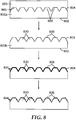
- One such method of creating a superhydrophobic film is illustrated in the flow chart according to Fig. 8 .
- the method may in some embodiments begin with providing a structured film 800b.
- the structured film 800b has a first major surface 802 and a second major surface 804 that is opposite the first major surface 802.
- On the second major surface 804 are a plurality of microstructures 830.
- the microstructures may be periodically spaced, as illustrated in Fig. 8 and also as shown in Fig. 3a .
- the microstructures may also be variably spaced as illustrated in Fig. 3b .
- the microstructures shape (closest to the base) may be prisms, as illustrated in Fig.
- microlenses a pattern that mimics sharkskin, or any other suitable microstructure shape.
- discrete flat portions 806 On top of at least some of the plurality of microstructures 830 are discrete flat portions 806. Discrete flat portions may be located on a majority of microstructures 830 or all of the microstructures. Where the microstructures are shorter than the plane upon which the discrete flat surface portions lie, the tops of the microstructures may still terminate in a peak, or lens shape, or other appropriate shape. An example would be those microstructures 1003b in Fig. 10 , where the peaks or tops 1080 of the microstructures are not as tall as plane 1020.
- the discrete flat portions 806 may generally be understood as substantially parallel to the first major surface 802. Where, as described with respect to Fig. 2 , there are slight variations, the flat portions 806 may be understood as being substantially parallel to the average plane of the first major surface 802.
- the structured film may be formed through some sort of replication process. This also may be understood as the first step of Fig. 8 .
- a mold is provided.
- the mold may be made out of any suitable material, such as a metal, e.g. nickel, or a polymer, to name a few.
- the mold is made up in part of a plurality of valleys 855. At least some of these valleys 855 will have a flat base 860.
- a composition 800a may be applied to the mold 850.
- the composition may be made up of any of the materials mentioned with regard to the structured film material above, e.g.
- the composition may next cured and then removed from the mold creating a negative of the mold, such that the flat bases 850 of valley 855 correspond to the discrete flat surface portions 806 on cured film 800b.
- a layer of nanoparticles 834 may be applied to the second major surface 804.
- the layer of nanoparticles should cover the entire second major surface 804, such that it covers flat portions 806 and those valley portions of microstructures 830 in between flat portions 806, as well as any potential flat portions that are located in valleys between microstructures or on microstructures in between the flat portions.
- the nanoparticles may be made up of any material that is conducive to serving as an etch mask for the film.
- the nanoparticles may be a slow-etching metal such as gold, or certain metal oxides, e.g., indium tin oxide, ZrO 2 , CeO 2 , Al 2 O 3 , or TiO 2 , just to name a few.
- the particles may be applied as part of a binder or coating suspension as desired to best disperse the particles on the surface 804.
- the nanoparticles may be applied to the second major surface by any appropriate coating method, such as dip coating, roll coating, die coating, spray coating, spin coating, and the like. Coating method, equipment, process conditions and compositions may be selected to achieve a substantially uniform coating over surfaces 804 and 806.
- the second major surface 804 is etched using the nanoparticles 834 as an etch mask.
- One particularly useful etching method for the etching step is reactive ion etching. Dry etching techniques such as laser ablation or ion beam milling may also be used.
- the result of the etching step is a plurality of nanostructures 844 that are located on the discrete flat portions 806, and remainder of microstructures 830 and any portions of surface in between them.
- the nanostructures may be broadly understood in the current description as either nanofeatures that protrude from the surface of microstructures 830, or valleys that are etched into the surface of microstructures 830. Where the nanoparticles used are slow-etching they may create either nanostructure valleys or protrusions that have high aspect ratios, such as 2 to 1, 3 to 1, 4 to 1, 5 to 1, 6 to 1 or even greater.
- the method may begin with providing a structured film 900b.
- the structured film 900b may have a first major surface 902 and a second major surface 904.
- the second major surface is opposite the first major surface 902 and includes a plurality of microstructures 930.
- the microstructures may be periodically spaced, as illustrated in Fig. 9 and also as shown in Fig. 3a .
- the microstructures may also be variably spaced as illustrated in Fig. 3b .
- the microstructures may be prisms, as illustrated in Fig. 9 , microlenses, a pattern that mimics sharkskin, or any other suitable microstructure shape.
- Discrete flat surface portions may be located on a majority or all of the microstructures. Where there are microstructures that are potentially shorter those microstructures may not have their peaks or tops 1080 flattened.
- the discrete flat portions are generally substantially parallel to the first major surface 902.
- the structured film may be formed through some sort of replication process. This also may be understood as the first step of Fig. 9 .
- a mold is provided as described with respect to Fig. 8 above.
- the mold is made up in part of a plurality of valleys 955. At least some of these valleys 955 will have a flat base 960.
- a composition 900a may be applied to the mold 950.
- the composition may be made up of any of the materials mentioned above with regard to the method of Fig. 8 or articles above described.
- the composition may next cured and then removed from the mold creating a negative of the mold, such that the flat bases 950 of valley 955 correspond to the discrete flat surface portions 906 on cured film 900b.
- a fluorochemical coating 922 may be applied to the second major surface 904.
- the fluorochemical coating should be applied to the entire second major surface 904, such that it covers both discrete flat portions 906 and the other portions of microstructures 930, as well as any portions of second major surface 904.
- the fluorochemical coating may generally be a hydrophobic, low surface-energy coating as described above in relation to Fig. 4 .
- the fluorochemical coating will be made up, at least in part, by a plurality of nanoparticles.
- the nanoparticles may potentially be made up of a dielectric, such as silicon dioxide.
- the nanoparticles may be fluoropolymer particles.
- the fluorochemical coating may further include an adhesion promoter, such as a silane as discussed with respect to Fig. 4 .
- the amount of prisms having discrete flat portions on the highest portion of the microstructures may be different, although each embodiment according to the present description will have at least some prisms having a truncated top, such that it has a discrete flat surface for a top.
- the film 1000 may have microstructures 1003a that have discrete flat portions 1006 on top of each microstructure 1003a.
- the film 1000 may also have microstructures 1003b on the film that do not terminate with a discrete flat portion, but rather terminate as a peak 1080 or in some other fashion.
- there are at least some discrete flat portions e.g. 206 in Fig. 2
- there may be other microstructures on second major surface 204 e.g. structures 1003b in Fig. 10 ) that are shorter than the plane at which the discrete flat portions lie. Weight and force may still be distributed across the microstructures 1003a having discrete flat portions 1080, while those microstructures that are shorter 1003b do not bear the weight.
- a silica nanoparticle coating component was prepared.
- 300g ofNalco 2329K (40wt.% solid), available from Nalco Chemical Company (Naperville, IL), and 300g of isopropanol were mixed together under rapid stirring.
- 7.96 grams of SILQUEST A-174 was added, and the mixture was stirred for 10 minutes.
- the mixture was heated to 85°C using a heating mantle for 6 hours.
- the resultant reaction mixture was solvent exchanged into methyl isobutyl ketone by alternate vacuum distillation and addition of 2600 grams of Methyl Isobutyl Ketone.
- the batch was concentrated further by vacuum distillation.
- the final mixture was a slightly translucent dispersion with 35.4% by weight A-174 modified 98nm.
- HFPO- refers to the end group F(CF(CF 3 )CF 2 O)aCF(CF 3 )- of the methyl ester F(CF(CF 3 )CF 2 O)aCF(CF 3 )C(O)OCH 2 .
- HFPO-C(O)CH 3 wherein "a” averages about 6.84, with an average molecular weight of 1314g/mol. It was prepared according to the method reported in U.S. Pat. No. 3,250,808 (Moore et al. ), incorporated herein by reference, with purification by fractional distillation.
- HFPO-Urethane acrylate solution (30%wt in methyl ethyl ketone) was prepared according to the method described in U.S. Patent Application Serial No. 11/277162 , incorporated herein by reference.
- the coating solution was prepared by mixing all the gradients listed in Table 1 under stirring to form a homogenous solution.
- Table 1 98 nm Silica Nanoparticle Coating Materials Supplier %solid as supplied Amount (grams) A-174 modified 2329K silica 35.4%wt in PM 10-20 DYNEON FPO 3740 20% in MEK 5-15 HFPO- Urethane Acrylates 30%wt in MEK 0-5 SR350 Satomer, Exton, PA 100% 4.29 MEK 80-150 IRGACURE 184 Ciba Specialty Chemicals, Basel, Switzerland 100% 0.1-0.8 The mixture was prepared by mixing the entire gradient together under rapid stirring.
- the silica nanoparticle coating was applied on top of a comparative prismatic film in which the prisms were spaced apart at a periodic pitch of 44 ⁇ m.
- the mixture was dried on the film in air for 15 minutes, and then cured using a Fusion Light-Hammer 6 UV processor available from UV Systems Inc. (Gaithersburg, Maryland) that was equipped with an H-bulb, operating under nitrogen atmosphere at 85% lamp power at a line speed of 13.7 meters/min. (2 passes).
- a prismatic film of the same dimensions as the comparative film except for having truncated tops was provided.
- the first prismatic film there were a series of peaks that extend from the base of the microstructure an average of 21.3 ⁇ m.
- the second prismatic film had a series of microstructures in which the top terminates at a flat portion. The distance from the base of the microstructures to the flat portion was an average of 16.5 ⁇ m (an average of 4.8 ⁇ m removed).
- the silica nanoparticle coating described above was then applied to the second prismatic film (the truncated prismatic film) in the same manner as described above on the prismatic film.
- the water contact angle of each of the films, the prismatic film with coating, and the truncated prismatic with coating, was then measured.
- Table 2 Water Contact Angle after Durability Test Sample Initial Water Contact Angle Water Contact Angle after Falling Sand Test Comparative Normal Prism Structure (44 ⁇ m pitch) with Coating 148.7° 138.4° Truncated Prism Structure (30 ⁇ m pitch) with Coating 148.6° 145.6°
Landscapes
- Laminated Bodies (AREA)
- Optical Elements Other Than Lenses (AREA)
- Manufacture Of Macromolecular Shaped Articles (AREA)
- Coating Of Shaped Articles Made Of Macromolecular Substances (AREA)
Description
- The present application relates generally to the following co-filed and commonly assigned U.S. Patent Applications: "Superhydrophobic Film Constructions", Attorney Docket No. 66910US002, and "Superhydrophobic Films", Attorney Docket No. 66911US002.
- The present description relates to superhydrophobic films and methods of making such films. More particularly, the present description relates to durable superhydrophobic films having a surface with discrete flat portions and valleys and different methods of producing such films.
- Hydrophobic films and coatings, and more particularly, superhydrophobic films and coatings have garnered considerable attention in recent years due to a number of attractive qualities. Highly hydrophobic surfaces have been recognized in nature, perhaps most prevalently on lotus leaves and also on cicada wings. Because of its hydrophobic properties, the lotus leaf is capable of self-cleaning by the washing away of dust particles and debris as water droplets roll off its surface. This ability to self-clean is desirable in a number of modern-day applications. However, it may be difficult to produce a self-cleaning superhydrophobic film that is capable of extended use in certain environments. The current description provides a superhydrophobic film that has a surface that is highly durable and weatherable in variable conditions, for example, outdoors, and performs very effectively without serious performance concerns after abrasive exposure.
-
US 2010/028604 A1 discloses hierarchical structures for superhydrophobic surfaces and methods of making the same. - Xing Yi Ling et al. discloses stable and transparent superhydrophobic nanoparticle films.
- In one aspect, the present description relates to a superhydrophobic film having a first major surface and a second major surface opposite the first major surface. The second major surface of the film has an array of prisms, wherein at least some of the prisms comprise discrete flat surface portions substantially parallel to the first major surface, and also has an array of valleys, where at least one valley is positioned between adjacent prisms of the array of prisms. Each of the discrete flat surface portions and valleys has a plurality of nanofeatures, and the superhydrophobic film exhibits a water contact angle of at least 140 degrees and a sliding angle of less than 10 degrees.
- In another aspect, the present description relates to a superhydrophobic film having a first major surface, a second major surface, and a low surface energy coating. The second major surface of the film has an array of prisms, wherein at least some of the prisms comprise discrete flat surface portions substantially parallel to the first major surface, and also has an array of valleys, where at least one valley is positioned between adjacent prisms of the array of prisms. The low surface energy coating is applied to the array of discrete flat surface portions and array of valleys, and comprises nanoparticles. The superhydrophobic film exhibits a water contact angle of at least 140 degrees and a sliding angle of less than 10 degrees.
- In another aspect, the present description relates to one more method of producing a superhydrophobic film. The method includes a step of providing a structured film that has a first major surface and a second major surface opposite the first major surface. The second major surface may include a plurality of microstructures, where at least some of the microstructures have a discrete flat surface portion on the top of the microstructure, the discrete flat surface portions being substantially parallel to the first major surface. The method further includes applying a fluorochemical coating to the second major surface. The fluorochemical coating includes a plurality of nanoparticles. The film may be provided by replication from a mold having valleys with at least some flat bases.
- In a final aspect, the present description relates to a method of producing a superhydrophobic film. The method includes a step of providing a structured film that has a first major surface and a second major surface opposite the first major surface. The second major surface may include a plurality of microstructures, where at least some of the microstructures have a discrete flat surface portion on the top of the microstructure, the discrete flat surface portions being substantially parallel to the first major surface. The method further includes the step of applying a layer of nanoparticles to the second major surface. Next, the second major surface is etched using the layer of nanoparticles as an etch mask. The result is a plurality of nanostructures on the discrete flat surface portions and remainder of the microstructures.
-
-
Figs. 1a-b are flow charts of superhydrophobic films that are degraded over time due to abrasion on microstructure surfaces. -
Fig. 2 is a cross-sectional view of a superhydrophobic film according to the present description. -
Figs. 3a-b are cross sectional views of films with different microstructure spacing intervals. -
Fig. 4 is a cross-sectional view of a superhydrophobic film according to the present description. -
Figs 5a-c are cross-sectional views of films with different valley shapes. -
Figs. 6a-6d provide illustrations of water droplets as related to measuring water contact angle, advancing angle, and receding angle. -
Fig. 7 is an apparatus for durability testing films. -
Fig. 8 illustrates a method for creating superhydrophobic films according to the present description. -
Fig. 9 illustrates a method for creating superhydrophobic films according to the present description. -
Fig. 10 is a cross-sectional view of superhydrophobic film with different microstructure shapes. -
Fig. 11 illustrates dimensional aspects of a cross-section of superhydrophobic film. -
Figs. 12a-c are different microstructure distributions for a superhydrophobic film. - Superhydrophobic films and surfaces are very desirable in a number of applications due to their ability to self-clean. Generally, a film may be considered "superhydrophobic" where the water contact angle is greater than 140 degrees. Superhydrophobic films may further be understood as generally nonwettable, as water beads off of the surface of the film upon contact. A further desirable quality for such films may be low contact angle hysteresis, that is, a small difference between the advancing and receding contact angles of the water droplet. A low contact angle hysteresis, or "sliding angle" allows for water beads to roll off of the surface of a film or other construction more easily. The combination of the ability to bead water that comes into contact with the surface of a structure and further roll the beaded water off of the surface is what makes the surface "self-cleaning."
- This ability to self-clean is desirable in a number of modern-day applications. For example, self-cleaning superhydrophobic surfaces may be useful on the sun-facing surfaces of solar (photovoltaic) cells, in anti-icing applications, corrosion prevention, anti-condensation applications, wind blades, traffic signals, edge seals, anti-fouling applications, and drag reduction and/or noise reduction for automobiles, aircraft, boats and microfluidic devices, just to name a few. Such films may also have valuable anti-reflection properties. There have therefore been attempts to create superhydrophobic films either by microstructuring a film's surface in a manner resembling that of the lotus leaf, coating the film with a hydrophobic chemical coating, or a combination thereof. Unfortunately, a number of these attempts have resulted in films that are not sufficiently durable in outdoor or other harsh environments. This is especially unfortunate due to the difficult conditions to which such films are exposed in the exemplary applications noted. Those attempts at producing films that are durable in harsh application environments may not display the highly superhydrophobic properties that are necessary for optimal self-cleaning performance. The present description therefore provides an improvement by offering a superhydrophobic film that is highly durable and weatherable in harsh conditions, for example, long-term use outdoors, and performs very effectively, even without a surface coating.
- In addition, an increasing number of applications require a superhydrophobic film construction that is transparent to visible or near-visible light. Besides having very superhydrophobic performance, the currently described films may exhibit very low reflectivity and therefore be highly transmissive. This is a highly beneficial property for applications where films are applied to solar cells, or any sort of window or light transmissive usage where the films are used for self-cleaning or anti-icing properties. The films described herein may reflect less than 5% of incident light, and may reflect less than 2% of incident light. In some application, only approximately 1% of light incident on the films is reflected.
- A number of superhydrophobic films may derive their superhydrophobic properties from the fact that they have microstructures or microparticles that are overlaid with nanostructures or nanoparticles. A great deal of difficulty arises, however, in preserving the nanoparticles or nanostructures on or near the peaks of the microstructures of the film as they degrade over time. An example of this effect is illustrated in
Fig. 1 . Here, nanostructures or nanocavities are formed into themicrostructures microstructures 103 may be worn away as illustrated in the flow chart. The result is aflat portion - In order to compete against this effect, the present description aims to preempt the wearing away of microstructures, and consequently, nanofeatures in or on those microstructures, or nanoparticles on those microstructures. As such, the present description provides for a microstructured film where at least some of the microstructures are truncated to provide a flat surface. This allows for a distribution of external forces (e.g. abrasion) over a larger area of the surface of the microstructures, resulting in a smaller force per area, such that the height of microstructures may be maintained, and the nanoparticles and nanofeatures may be preserved at greater length, providing for greater performance.
- One embodiment of a film according to the present description is illustrated in
Fig. 2 . As shown inFig. 2 ,superhydrophobic film 200 has a firstmajor surface 202. The firstmajor surface 202 may be flat as illustrated in the figure. In other embodiments, the surface may have slight matte variation or microstructures, but in such cases, the film may generally be understood as having an average height that lies in a flat plane. Thesuperhydrophobic film 200 also has a secondmajor surface 204 that is opposite the firstmajor surface 202. The second major surface may be understood as being made up of at least two different sub-parts. The first subpart of the second major surface is an array of discreteflat surface portions 206. Each of the discreteflat surface portions 206 is substantially parallel to the firstmajor surface 202. As mentioned above, generally the firstmajor surface 202 will be flat. However, where there is slight variation in the surface, the flat discrete portions will lie parallel to the flat plane that is the average height of firstmajor surface 202. - The second subpart of second
major surface 204 is an array ofvalleys 208. Eachvalley 208 in the array of valleys is positioned between adjacent discreteflat surface portions 206. InFig. 2 , thevalleys 208 are shown as having facets that terminate at acommon point 207. However, valleys are also contemplated that have flat or near-flat bottoms of the valley, as well as side facets of microstructures that have sudden discontinuities in slope. Further, the valleys may haveside walls 212 that are flat, as shown inFig. 2 . In other embodiments, theside walls 212 may be curved, such as in a portion of a microlens. Examples of just a few different shapes that valleys may take according to the present description are illustrated inFigs. 5a-5c . Specifically, the valley may have flat side walls as illustrated inFig. 5a , or may have curved sidewalls that are concave down, such as shown inFig. 5b . The side walls may also be curved and concave up, as illustrated inFig. 5c . A number of other valley shapes are also contemplated. - In addition, as illustrated in
Fig. 3a-b the discreteflat portions 206 may be spaced apart in a constant periodic manner, as shown inFig. 3a , or may be variably spaced apart at different distances along the second major surface, as illustrated byflat portions 206 inFig. 3b . - A better understanding of the dimensions of microstructures according to the present description may be gained by reference to
Fig. 11 andfilm 1100. In a number of embodiments, the structured film will be made up ofmicrostructures 1102, and that portion below the microstructures that is a solid portion of the film that connects and stabilizes the film without varying structure. This portion may be understood as "land" 1104. The land generally should be of a sufficient thickness to generate stability for the entire film. The land, for example may have athickness 1150 than is at least greater than 25 microns, and often greater than 100 microns. The microstructures may have aheight 1120 that is either the distance fromland 1104 to the plateau or peak at which the top of themicrostructure 1102 terminates. Theheight 1120 ofmicrostructure 1102 may generally range from about 0.150 microns to about 1000 microns, or potentially from about 1 micron to about 500 microns. In general, at least some of the microstructures will be truncated such that they have a plateau at the peak of the microstructure. The plateau generally will have alateral distance 1160 across the plateau (or discrete flat surface portion) of between about 0.1 microns up to about 20 microns. In addition, thefilm 1100 may have a pitch that is defined as the distance betweenadjacent microstructures 1102. Generally, the pitch of a microstructured film according to the present description is between about 0.15 microns and about 1000 microns, or potentially between about 1 and about 500 microns. Thefilm 1100 is also made up of valleys that havebases 1190. The distance across thevalley base 1140 may of course be as small as 0 microns, but may also range up to 100 microns. In fact, in some embodiments, the distance across the valley base may be up to four times the height of the microstructures. Where the microstructures utilized are prisms rather than a variable sloped microstructure (e.g. a lens), any number of peak angles θP are considered useful. For example, peak angle θP may range in some embodiments from about 30 degrees to about 90 degrees. In many embodiments, the peak angle will range from about 50 degrees to about 70 degrees. - In addition, microstructure placement and dimensions may vary across the surface of the film. A better understanding of this may be gained by reference to
Figs. 12a-c , which illustrate an array of microstructures, shown here without any truncation. For example, an array of microstructures (shown here without any truncation) may vary in one, two or three dimensions. InFig. 12a , the microstructures may be structures that identically run thelength 1280 of the film at the same height along thevertical direction 1290 without any segmentation. However, across thewidth 1270 of thefilm 1270, or across a first dimension, the film is segmented into different discrete microstructures. In addition, as shown inFig. 12b , the microstructure may vary in two directions. For example, the structures may be segmented as inFig. 12a along thewidth 1270 of the film, but also be segmented along thelength 1280 of the film (or second dimension). In such a case, discrete prisms are located along both axes. Here, however, the structures are all the same height in the vertical direction (or third dimension) 1290. Finally, as shown inFig. 12c , the structures may be segmented along both the width and length of the film, but may also vary in the height of the microstructures across the film in the vertical direction 1290 (or third dimension). In any of these three scenarios the microstructures may be directly adjacent to one another or may be spaced apart by some portion of film that is flat. Of course, although illustrated here with respect to various prismatic embodiments, the microstructures may be lens shaped, or any other suitable structure. - Returning to
Fig. 2 , the secondmajor surface 204 may include microstructures on the second major surface that do not have discrete flat portions. An example of such a construction is illustrated inFig. 10 withfilm 1000. In this construction there are discreteflat surface portions 1006. In one respect the discreteflat surface portions 1006 are the tops oftruncated microstructures 1003a. Two adjacent discreteflat surface portions single valley 1008a. The same is true with discreteflat surface portions valley 1008b. However, as they are the two closest discrete flat surface portions to one another,portions valleys smaller microstructures 1003b. These smaller microstructures will generally be shorter than the height of theplane 1020 upon which the discreteflat surface portions 1006 commonly lie. Themicrostructures 1003b may terminate at apeak 1080, or may be a lens shape or any other appropriate shape. As discussed below with respect to the valleys and flat surface portions, themicrostructures 1003b may also have nanofeatures or nanoparticle coatings. In some embodiments, all of themicrostructures flat surface portion 1006. However, in other embodiments, only some of the microstructures will have a discrete flat surface portion. In some embodiments, a majority of the microstructures will have discrete flat surface portions. - Returning to
Fig. 2 , each of the discreteflat portions 206 also includes a plurality ofnanofeatures 210. Thevalleys 208 also have a plurality ofnanofeatures 210 on their surface. The scale of the nanofeatures will generally be much smaller than the depth ofvalleys 208. Thenanofeatures 210 may be protrusions from thesurface 204, or may be cavities that enter thesurface 204. In either case, however, the nanofeatures will be very thin and optionally fairly long in dimension. For example, the nanofeatures may have an aspect ratio of at least 1 to 1, at least 2 to 1, or at least 3 to 1, or at least 4 to 1, or at least 5 to 1, or at least 6 to 1. - Two of the most important measurements in determining just how superhydrophobic a film or coating is are that of water contact angle and sliding angle (or contact angle hysteresis). The water contact angle may be measured with a static contact angle measurement device, such as the Video Contact Angle System: DSA100 Drop Shape Analysis System from Kruess GmbH (Hamburg, Germany). In this particular system, a machine is equipped with a digital camera, automatic liquid dispensers, and sample stages allowing a hands-free contact angle measurement via automated placement of a drop of water (where the water drop has a size of approximately 5 µl). The drop shape is captured automatically and then analyzed via Drop Shape Analysis by a computer to determine the static, advancing, and receding water contact angle. Static water contact angle may be generally understood as the general "water contact angle" described and claimed herein.
- The water contact angle may most simply be understood as the angle at which a liquid meets a solid surface. As shown in
Fig. 6a , where a surface offilm 610a is not very hydrophobic, thewater drop 601a will flatten on the surface. Atangential line 603a may be drawn from interface point of the drop along the edge of the drop. The contact angle θC1 is the angle between thistangent line 603a, and the plane of thedrop 601a andfilm 610a interface.Fig. 6a shows a water droplet that is not beading along the surface and therefore a contact angle θC1 that is well below 90 degrees. Conversely,film 610b inFig. 6b is hydrophobic. As such, thewater droplet 601b experiences more of a beading effect off of the surface. Therefore the tangent line 603b along the drop's edge angles out away from the drop, and a water contact angle θC2 of greater than 90 degrees, and potentially greater than 140 or 150 degrees is achieved. - The "sliding angle" or "contact angle hysteresis" is defined as the difference between the advancing and receding water contact angles. Advancing water contact angle and receding water contact angles relate not just to static conditions, but to dynamic conditions. With reference to
Fig. 6c , the advancing water contact angle θCA is measured by addingfurther water volume 611c into thedrop 601c. As more water is added, the droplet increases in volume and the water contact angle also increases. When a critical volume is reached, the intersection of the droplet surface with the film will jump outward such thatdroplet 601c will reform into a droplet withshape 613c, and the intersection of the droplet and film surfaces will move fromposition 621c toposition 623c. The water contact angle θCA is the angle of the drop immediately before the intersection jumps. In the same vein, water receding angle is shown inFig. 6d . Here the higher volume drop haswater 611d slowly removed from it. The surface ofinitial drop 601d intersects thefilm 610d atposition 621d. At a given volume, the intersection jumps to position 623d. Thetangent line 603d that traces the edge of the drop immediately before this jump defines the receding water contact angle θCR. - Again returning to
Fig. 2 , thesuperhydrophobic film 200 also exhibits strong hydrophobic properties. In at least one embodiment, thesuperhydrophobic film 200 has a static water contact angle of at least 140 degrees, or potentially at least 145 degrees or even over 150 degrees. Thesuperhydrophobic film 200 also has a sliding angle of less than 10 degrees or less than 5 degrees, and potentially even less than about 3 degrees. - As stated, the second
major surface 204 has an array of discreteflat portions 206, each of which is covered innanofeatures 210. The discrete flat portions serve to spread the amount of incident force upon the film over a larger surface area. As such, thesurface 204 is more difficult to degrade and nanofeatures 210 andflat portions 206 may remain intact, at least for a longer exposure time. Because of this desire to spread force across the discrete flat portions, in at least some embodiments, it is beneficial for the discrete flat portions to be positioned on acommon plane 220. It should be understood thatfilm 200 may be made out of any number of suitable materials. In some embodiments, thefilm 200 may be made in part of a silicone polymer, such as poly(dimethylsiloxane) (PDMS). The film may be a majority by weight PDMS or potentially even up to or greater than 95wt.% PDMS. In some embodiments, thefilm 200 may be made of a silicone polymer in which some of the silicon atoms have other groups that may be aryl, for example phenyl, alkyl, for example ethyl, propyl, butyl or octyl, , fluororalkyl, for example 3,3,3-trifluoropropyl, or arylalkyl, for example 2-phenylpropyl. The silicone polymers may also contain reactive groups, such as vinyl, silicon-hydride (Si-H), silanol (Si-OH), acrylate, methacrylate, epoxy, isocyanate, anhydride, mercapto and chloroalkyl. These silicones may be thermoplastic or they may be cured, for example, by condensation cure, addition cure of vinyl and Si-H groups, or by free-radical cure of pendant acrylate groups. They may also be cross-linked with the use of peroxides. Such curing may be accomplished with the addition of heat or actinic radiation. Other useful polymers include polyurethanes, fluoropolymers including fluororelastomers, polyacrylates and polymethacrylates. In another embodiment, polymers with a glass transition temperature of at least 25 degrees C are useful. In at least some embodiments, the film may be an elastomer. An elastomer may be understood as a polymer with the property of viscoelasticity (or elasticity) generally having notably low Young's modulus and high yield strain compared with other materials. The term is often used interchangeably with the term rubber, although the latter is preferred when referring to cross-linked polymers. - In addition, the film according to the present description may be positioned on a substrate. The film will generally be positioned such that the first major surface is adjacent the substrate. The substrate may be made from any number of suitable materials. For example, in some embodiments, the substrate may be made from the same materials as the film. In other exemplary embodiments, the substrate may be made of polyimide or more commonly used substrates. Specifically, glass, metal or plastic substrates may be appropriate, as well as other suitable alternatives such as silicon wafers.
- Another embodiment of a superhydrophobic film contemplated according to the present description is illustrated in
Fig. 4. Fig. 4 provides asuperhydrophobic film 400 that has a firstmajor surface 402. The firstmajor surface 402 may be provided in the same manner as firstmajor surface 202 ofFig. 2 . Opposite the firstmajor surface 402 on thefilm 400 is a secondmajor surface 404. The second major surface may include an array of discreteflat surface portions 406, and an array ofvalleys 408. Each valley may be positioned between two adjacent discrete flat surface portions. As with the film described inFig. 2 , the discreteflat surface portions 406 may in at least some embodiments be located on acommon plane 420 such that force is distributed evenly along the faces of thesecond surface 404. Also as with the film described inFig. 2 , the film may further include microstructures (e.g. 1003b inFig. 10 ) that are also placed between discrete flat surface portions, along with the valleys in between such portions. - A low
surface energy coating 422 is applied over the discreteflat surface portions 406 andvalleys 408. A low surface energy coating may generally be understood as a coating that, on a flat surface, has a water contact angle of greater than 110 degrees. The low surface energy coating may also be coated over anynon-truncated microstructure 1003b that does not terminate in a discrete flat surface portion. The lowsurface energy coating 422 exhibits hydrophobic properties that, in conjunction with the structure offilm 400 contribute to the heightened superhydrophobicity of the film. The low surface energy coating may be any known hydrophobic coating, such as a nanocomposite coating. In some cases, the nanocomposite coating could be, at least in part, a fluorochemical coating. In some cases, the low surface energy coating may be made up of an appropriate silane, e.g. fluoroalkyl substituted silane. In at least some embodiments, the lowsurface energy coating 422 is made up in part, and potentially in large part, to a plurality ofnanoparticles 424. Thenanoparticles 424 may be of a polymer, such as a fluoropolymer, a dielectric, such as silicon dioxide, ZrO2, Al2O3, TriO2, CeO2, ITO, or a metal, such as gold. The nanoparticles may be of a size from about 5nm to 1 micron. In some embodiments, the low surface energy coating may include, in part, an adhesion promoter to further increase durability and better hold the coating on thesurface portions 406 andvalleys 408. In other exemplary embodiments, an adhesion promoter may be applied separately from the low surface energy coating. One example of such an adhesion promoter is a silane, such as SILQUEST A-1106, available from Momentive Performance Materials, Inc. (Wilton, CT). Exemplary fluoropolymers and adhesion promoters that may be particularly useful for the low surface energy coating currently described may be found in commonly owned and assignedU.S. Patent No. 7,323,514 in the section beginning at col. 5, line 5 and concluding at column 10, line 42.U.S. Patent No. 7,323,514 is hereby incorporated herein by reference in its entirety. - Where nanoparticles are applied as part of a coating, the nanoparticles may also have surface treatment agents applied over them. Exemplary surface treatment agents include N-(3-triethoxysilylpropyl) methoxyethoxyethoxyethyl carbamate, N-(3- triethoxysilylpropyl) methoxyethoxyethoxyethyl carbamate, 3- (methacryloyloxy)propyltrimethoxysilane, 3-acryloxypropyltrimethoxysilane, 3-(methacryloyloxy)propyltriethoxysilane, 3-(methacryloyloxy) propylmethyldimethoxysilane, 3-(acryloyloxypropyl) methyldimethoxysilane, 3-(methacryloyloxy)propyldimethylethoxysilane, 3-(methacryloyloxy) propyldimethylethoxysilane, vinyldimethylethoxysilane, phenyltrimethoxysilane, n-octyltrimethoxysilane, dodecyltrimethoxysilane, octadecyltrimethoxysilane, propyltrimethoxysilane, hexyltrimethoxysilane, vinylmethyldiacetoxysilane, vinylmethyldiethoxysilane, vinyltriacetoxysilane, vinyltriethoxysilane, vinyltriisopropoxysilane, vinyltrimethoxysilane, vinyltriphenoxysilane, vinyltri-t-butoxysilane, vinyltris-isobutoxysilane, vinyltriisopropenoxysilane, vinyltris(2- methoxyethoxy)silane, styrylethyltrimethoxysilane, mercaptopropyltrimethoxysilane, 3-glycidoxypropyltrimethoxysilane, acrylic acid, methacrylic acid, oleic acid, stearic acid, dodecanoic acid, 2-[2-(2-methoxyethoxy)ethoxy]acetic acid (MEEAA), beta-carboxyethylacrylate (BCEA), 2-(2-methoxyethoxy)acetic acid, methoxyphenyl acetic acid, and mixtures thereof.
- The
superhydrophobic film 400 also exhibits strong hydrophobic properties. In at least one embodiment, thesuperhydrophobic film 200 has a water contact angle of at least 140 degrees, or potentially at least 145 degrees or even over 150 degrees. Thesuperhydrophobic film 200 also has a sliding angle of less than 10 degrees or less than 5 degrees, and potentially even less than about 3 degrees. - One of the primary improvements of the current film over the art is the durability exhibited by the film. In order to gauge the ability of films to withstand exposure to the elements, it is valuable to expose them to a test condition setting that provides a simulation of the elements. One standard approach for such a simulation is called a falling sand test or falling sand exposure test (as in ASTM standard D 968). The durability of the films according to the present description was tested by dropping a given volume of sand over a predetermined amount of time at a given distance and angle from the surface of the film.
Fig. 7 provides a general illustration of theapparatus 700 used to test the films by falling sand. In one exemplary test one kilogram of standardized sand is placed inreservoir 731.Reservoir 731 is connected to asupport beam 745 by first connectingmeans 741. A given amount of sand constantly moves fromreservoir 731 intotube 733. It falls within the tube 733 adistance 763 of 90cm. The steady stream of sand then exitstube 733 attube exit 735 and travels towardfilm 751.Film 751 is securely positioned beneath the stream of sand byfilm support structure 747. The film support structure may also be positioned in place by securing to supportbeam 745 through second connectingmeans 749. Thefilm support structure 747 positions the film such that the plane of the film is at a 45 degree angle with the primary direction of the stream of sand. Therefore, with reference toFig. 7 , the angle θF is 45 degrees. The primary contact point onfilm 751 may be placed apredetermined distance 753 from thetube exit 735 having a diameter of 2cm. In this test, thedistance 753 is 25mm. - The "falling sand" test performed as specified above generally will create a great deal of abrasion on the surface of a film, especially with a film that is microstructured and/or nanofeatured. As such, it is to be expected that most superhydrophobic film constructions in the art that had to go through the test would see serious degradation to the structures on the film's surface. This would necessarily result in lower hydrophobicity (i.e. lower water contact angles and high sliding angles).
- The films described above exhibit superhydrophobic properties even after exposure to the falling sand test herein described. For example, after exposure to the falling sand test, the water contact angle of such a film may be greater than 140 degrees, or even greater than 145 degrees. The sliding angle may remain below 5 degrees, and potentially be even less than 3 degrees.
- The present description also relates to methods of creating superhydrophobic films. One such method of creating a superhydrophobic film is illustrated in the flow chart according to
Fig. 8 . The method may in some embodiments begin with providing astructured film 800b. Thestructured film 800b has a firstmajor surface 802 and a secondmajor surface 804 that is opposite the firstmajor surface 802. On the secondmajor surface 804 are a plurality ofmicrostructures 830. The microstructures may be periodically spaced, as illustrated inFig. 8 and also as shown inFig. 3a . The microstructures may also be variably spaced as illustrated inFig. 3b . The microstructures shape (closest to the base) may be prisms, as illustrated inFig. 8 , microlenses, a pattern that mimics sharkskin, or any other suitable microstructure shape. On top of at least some of the plurality ofmicrostructures 830 are discreteflat portions 806. Discrete flat portions may be located on a majority ofmicrostructures 830 or all of the microstructures. Where the microstructures are shorter than the plane upon which the discrete flat surface portions lie, the tops of the microstructures may still terminate in a peak, or lens shape, or other appropriate shape. An example would be thosemicrostructures 1003b inFig. 10 , where the peaks or tops 1080 of the microstructures are not as tall asplane 1020. The discreteflat portions 806 may generally be understood as substantially parallel to the firstmajor surface 802. Where, as described with respect toFig. 2 , there are slight variations, theflat portions 806 may be understood as being substantially parallel to the average plane of the firstmajor surface 802. - Another step may be understood as part of this method that occurs before the structured film is present. The structured film may be formed through some sort of replication process. This also may be understood as the first step of
Fig. 8 . There, a mold is provided. The mold may be made out of any suitable material, such as a metal, e.g. nickel, or a polymer, to name a few. The mold is made up in part of a plurality ofvalleys 855. At least some of thesevalleys 855 will have aflat base 860. Acomposition 800a may be applied to themold 850. The composition may be made up of any of the materials mentioned with regard to the structured film material above, e.g. a silicone polymer such as PDMS, a polyurethane, polyacrylate, or any of the other large number of materials noted above. The composition may next cured and then removed from the mold creating a negative of the mold, such that theflat bases 850 ofvalley 855 correspond to the discreteflat surface portions 806 on curedfilm 800b. - In the next step of the method according to
Fig. 8 , after providing thestructured film 800b, a layer ofnanoparticles 834 may be applied to the secondmajor surface 804. The layer of nanoparticles should cover the entire secondmajor surface 804, such that it coversflat portions 806 and those valley portions ofmicrostructures 830 in betweenflat portions 806, as well as any potential flat portions that are located in valleys between microstructures or on microstructures in between the flat portions. Generally, the nanoparticles may be made up of any material that is conducive to serving as an etch mask for the film. For example, the nanoparticles may be a slow-etching metal such as gold, or certain metal oxides, e.g., indium tin oxide, ZrO2, CeO2, Al2O3, or TiO2, just to name a few. The particles may be applied as part of a binder or coating suspension as desired to best disperse the particles on thesurface 804. The nanoparticles may be applied to the second major surface by any appropriate coating method, such as dip coating, roll coating, die coating, spray coating, spin coating, and the like. Coating method, equipment, process conditions and compositions may be selected to achieve a substantially uniform coating oversurfaces - In the subsequent step, the second
major surface 804 is etched using thenanoparticles 834 as an etch mask. One particularly useful etching method for the etching step is reactive ion etching. Dry etching techniques such as laser ablation or ion beam milling may also be used. The result of the etching step is a plurality ofnanostructures 844 that are located on the discreteflat portions 806, and remainder ofmicrostructures 830 and any portions of surface in between them. The nanostructures may be broadly understood in the current description as either nanofeatures that protrude from the surface ofmicrostructures 830, or valleys that are etched into the surface ofmicrostructures 830. Where the nanoparticles used are slow-etching they may create either nanostructure valleys or protrusions that have high aspect ratios, such as 2 to 1, 3 to 1, 4 to 1, 5 to 1, 6 to 1 or even greater. - Another method for creating a superhydrophobic film according to the present description is provided in
Fig. 9 . The method may begin with providing astructured film 900b. Thestructured film 900b may have a firstmajor surface 902 and a secondmajor surface 904. The second major surface is opposite the firstmajor surface 902 and includes a plurality ofmicrostructures 930. The microstructures may be periodically spaced, as illustrated inFig. 9 and also as shown inFig. 3a . The microstructures may also be variably spaced as illustrated inFig. 3b . The microstructures may be prisms, as illustrated inFig. 9 , microlenses, a pattern that mimics sharkskin, or any other suitable microstructure shape. On top of at least some of the plurality ofmicrostructures 930 is a discreteflat portion 906. Discrete flat surface portions may be located on a majority or all of the microstructures. Where there are microstructures that are potentially shorter those microstructures may not have their peaks or tops 1080 flattened. The discrete flat portions are generally substantially parallel to the firstmajor surface 902. - Another step may be understood as part of this method that occurs before the structured film is present. The structured film may be formed through some sort of replication process. This also may be understood as the first step of
Fig. 9 . There, a mold is provided as described with respect toFig. 8 above. The mold is made up in part of a plurality ofvalleys 955. At least some of thesevalleys 955 will have aflat base 960. Acomposition 900a may be applied to themold 950. The composition may be made up of any of the materials mentioned above with regard to the method ofFig. 8 or articles above described. The composition may next cured and then removed from the mold creating a negative of the mold, such that theflat bases 950 ofvalley 955 correspond to the discreteflat surface portions 906 on curedfilm 900b. - Finally, in the final step of the method of
Fig. 9 , after providing the structured film, afluorochemical coating 922 may be applied to the secondmajor surface 904. The fluorochemical coating should be applied to the entire secondmajor surface 904, such that it covers both discreteflat portions 906 and the other portions ofmicrostructures 930, as well as any portions of secondmajor surface 904. The fluorochemical coating may generally be a hydrophobic, low surface-energy coating as described above in relation toFig. 4 . In some embodiments, the fluorochemical coating will be made up, at least in part, by a plurality of nanoparticles. As discussed with the article described with respect toFig. 4 , the nanoparticles may potentially be made up of a dielectric, such as silicon dioxide. In other embodiments, the nanoparticles may be fluoropolymer particles. The fluorochemical coating may further include an adhesion promoter, such as a silane as discussed with respect toFig. 4 . - In any of the methods that are shown in
Fig. 8 andFig. 9 , the amount of prisms having discrete flat portions on the highest portion of the microstructures may be different, although each embodiment according to the present description will have at least some prisms having a truncated top, such that it has a discrete flat surface for a top. For example, looking toFig. 10 , andfilm 1000, some of the films ofFig. 8 and9 , as well as those described in the articles described with respect toFigs. 2 and4 , thefilm 1000 may havemicrostructures 1003a that have discreteflat portions 1006 on top of each microstructure 1003a. However, thefilm 1000 may also havemicrostructures 1003b on the film that do not terminate with a discrete flat portion, but rather terminate as apeak 1080 or in some other fashion. For each of the embodiments described herein, there are at least some discrete flat portions (e.g. 206 inFig. 2 ) that rise to acommon plane 220. However there may be other microstructures on second major surface 204 (e.g. structures 1003b inFig. 10 ) that are shorter than the plane at which the discrete flat portions lie. Weight and force may still be distributed across themicrostructures 1003a having discreteflat portions 1080, while those microstructures that are shorter 1003b do not bear the weight. - A silica nanoparticle coating component was prepared. In a 1L flask, equipped with a condenser and a thermometer, 300g ofNalco 2329K (40wt.% solid), available from Nalco Chemical Company (Naperville, IL), and 300g of isopropanol were mixed together under rapid stirring. Next, 7.96 grams of SILQUEST A-174 was added, and the mixture was stirred for 10 minutes. The mixture was heated to 85°C using a heating mantle for 6 hours. Finally, the resultant reaction mixture was solvent exchanged into methyl isobutyl ketone by alternate vacuum distillation and addition of 2600 grams of Methyl Isobutyl Ketone. The batch was concentrated further by vacuum distillation. The final mixture was a slightly translucent dispersion with 35.4% by weight A-174 modified 98nm.
- 100 g of Dyneontm FPO 3740 and 400 g of MEK was added to a brown bottle. The polymer was dissolved under ultrasonic treatment, which yielded a clear DYNEON FFO 3740 solution in MEK with 20%wt solid.
- "HFPO-", as used in the examples, unless otherwise noted, refers to the end group F(CF(CF3)CF2O)aCF(CF3)- of the methyl ester F(CF(CF3)CF2O)aCF(CF3)C(O)OCH2. (HFPO-C(O)CH3), wherein "a" averages about 6.84, with an average molecular weight of 1314g/mol. It was prepared according to the method reported in
U.S. Pat. No. 3,250,808 (Moore et al. ), incorporated herein by reference, with purification by fractional distillation. - HFPO-Urethane acrylate solution (30%wt in methyl ethyl ketone) was prepared according to the method described in
U.S. Patent Application Serial No. 11/277162 , incorporated herein by reference. - The coating solution was prepared by mixing all the gradients listed in Table 1 under stirring to form a homogenous solution.
Table 1: 98 nm Silica Nanoparticle Coating Materials Supplier %solid as supplied Amount (grams) A-174 modified 2329K silica 35.4%wt in PM 10-20 DYNEON FPO 3740 20% in MEK 5-15 HFPO- Urethane Acrylates 30%wt in MEK 0-5 SR350 Satomer, Exton, PA 100% 4.29 MEK 80-150 IRGACURE 184 Ciba Specialty Chemicals, Basel, Switzerland 100% 0.1-0.8 - After mixture, the silica nanoparticle coating was applied on top of a comparative prismatic film in which the prisms were spaced apart at a periodic pitch of 44 µm. The mixture was dried on the film in air for 15 minutes, and then cured using a Fusion Light-Hammer 6 UV processor available from UV Systems Inc. (Gaithersburg, Maryland) that was equipped with an H-bulb, operating under nitrogen atmosphere at 85% lamp power at a line speed of 13.7 meters/min. (2 passes).
- Next, a prismatic film of the same dimensions as the comparative film except for having truncated tops was provided. In the first prismatic film there were a series of peaks that extend from the base of the microstructure an average of 21.3µm. The second prismatic film had a series of microstructures in which the top terminates at a flat portion. The distance from the base of the microstructures to the flat portion was an average of 16.5µm (an average of 4.8µm removed). The silica nanoparticle coating described above was then applied to the second prismatic film (the truncated prismatic film) in the same manner as described above on the prismatic film. The water contact angle of each of the films, the prismatic film with coating, and the truncated prismatic with coating, was then measured.
- Following this performance measurement, each of the two films was subjected to the ASTM falling sand test as explained further above in the description. The water contact angle of the two films was again tested. Table 2 provides the performance results.
Table 2: Water Contact Angle after Durability Test Sample Initial Water Contact Angle Water Contact Angle after Falling Sand Test Comparative Normal Prism Structure (44µm pitch) with Coating 148.7° 138.4° Truncated Prism Structure (30µm pitch) with Coating 148.6° 145.6° - As shown in Table 2, initially the superhydrophobic properties of the two films were nearly identical, with water contact angles of 148.7° and 148.6° respectively. However, after durability testing, the water contact angle of the prism film with no truncation of the peak was reduced below 140° to 138.4°. The truncated prism structure still had strong superhydrophobic performance after the test, with a water contact angle of 145.6°. The example provides a valuable illustration of the ability of the films of the current description to remain highly superhydrophobic despite harsh environmental conditions and abrasion experienced in a number of real-world applications.
- Although specific embodiments have been illustrated and described herein, it will be appreciated by those of ordinary skill in the art that a variety of alternate and/or equivalent implementations can be substituted for the specific embodiments shown and described without departing from the scope of the present disclosure. This application is intended to cover any adaptations or variations of the specific embodiments discussed herein. Therefore, it is intended that this disclosure be limited only by the claims and the equivalents thereof.
Claims (14)
- A superhydrophobic film, comprising:a first major surface; anda second major surface opposite the first major surface, the second major surface comprising an array of prisms, wherein at least some of the prisms comprise discrete flat surface portions, wherein each of the discrete flat portions is substantially parallel to the first major surface; and the second major surface further comprising an array of valleys, wherein at least one valley is positioned between adjacent prisms of the array of prisms,wherein each of the discrete flat surface portions and valleys comprises a plurality of nanofeatures, andwherein the superhydrophobic film has a water contact angle of at least 140 degrees and a sliding angle of less than 10 degrees.
- The superhydrophobic film of claim 1, wherein the valleys have flat side surfaces.
- The superhydrophobic film of claim 1, wherein the valleys have curved side surfaces.
- The superhydrophobic film of claim 1, wherein the film is made of a polymer that is at least 95% PDMS.
- The superhydrophobic film of claim 1, wherein the nanofeatures have an aspect ratio of at least 5 to 1.
- The superhydrophobic film of claim 1, wherein the discrete flat portions are periodically spaced apart.
- The superhydrophobic film of claim 1, wherein the discrete flat portions are variably spaced apart.
- A superhydrophobic film, comprising:a first major surface;a second major surface opposite the first major surface, the second major surface comprising an array of prisms, wherein at least some of the prisms comprise discrete flat surface portions, wherein each of the discrete flat portions is substantially parallel to the first major surface; and the second major surface further comprising an array of valleys, wherein at least one valley is positioned between adjacent prisms of the array of prisms; anda low surface energy coating, the low surface energy coating applied to the array of discrete flat surface portions and array of valleys, wherein the low surface energy coating comprises nanoparticles,wherein the superhydrophobic film has a water contact angle of at least 140 degrees and a sliding angle of less than 10 degrees.
- The superhydrophobic film of claim 1 or 8, wherein the discrete flat portions are positioned on a common plane.
- The superhydrophobic film of claim 8, wherein the low surface energy coating comprises fluoropolymer.
- The superhydrophobic film of claim 1 or 8, wherein the film has a water contact angle of at least 150 degrees and a sliding angle of less than 5 degrees.
- The superhydrophobic film of claim 1 or 8, wherein the film has a water contact angle of greater than 145 degrees after exposure to a standard falling sand test.
- The superhydrophobic film of claim 8, wherein the superhydrophobic film comprises an adhesion promoter.
- The superhydrophobic film of claim 1 or 8, wherein the film reflects less than 2% of incident light.
Applications Claiming Priority (2)
| Application Number | Priority Date | Filing Date | Title |
|---|---|---|---|
| US40782010P | 2010-10-28 | 2010-10-28 | |
| PCT/US2011/057073 WO2012058090A1 (en) | 2010-10-28 | 2011-10-20 | Superhydrophobic films |
Publications (2)
| Publication Number | Publication Date |
|---|---|
| EP2632612A1 EP2632612A1 (en) | 2013-09-04 |
| EP2632612B1 true EP2632612B1 (en) | 2016-05-25 |
Family
ID=44947194
Family Applications (1)
| Application Number | Title | Priority Date | Filing Date |
|---|---|---|---|
| EP11782275.9A Not-in-force EP2632612B1 (en) | 2010-10-28 | 2011-10-20 | Superhydrophobic films |
Country Status (5)
| Country | Link |
|---|---|
| US (1) | US20130216784A1 (en) |
| EP (1) | EP2632612B1 (en) |
| JP (1) | JP5847187B2 (en) |
| CN (1) | CN103282133B (en) |
| WO (1) | WO2012058090A1 (en) |
Families Citing this family (33)
| Publication number | Priority date | Publication date | Assignee | Title |
|---|---|---|---|---|
| CN103534934B (en) | 2011-05-09 | 2016-09-14 | 3M创新有限公司 | There are the architectonics goods of photovoltaic cell and visible transmission reflector |
| WO2014022631A1 (en) | 2012-08-01 | 2014-02-06 | 3M Innovative Properties Company | Fuel injectors with improved coefficient of fuel discharge |
| US9221990B2 (en) | 2012-11-14 | 2015-12-29 | 3M Innovative Properties Company | Fluoropolymer coatings suitable for films of photovoltaic modules |
| DE102013109621B4 (en) | 2012-11-19 | 2021-02-11 | Karlsruher Institut für Technologie | Process for producing a shaped body with a superhydrophobic surface and shaped body obtainable with this process and its use |
| US9728669B2 (en) * | 2013-03-06 | 2017-08-08 | Sino-American Silicon Products Inc. | Solar cell and method of manufacturing the same |
| CN103172017B (en) * | 2013-03-25 | 2017-02-22 | 北京大学 | Method for manufacturing super-hydrophobic silicon substrate |
| US20160075883A1 (en) * | 2013-04-25 | 2016-03-17 | The Ohio State University | Methods of fabricating superhydrophobic, optically transparent surfaces |
| CN105378945A (en) | 2013-07-01 | 2016-03-02 | 3M创新有限公司 | Solar energy devices |
| EP3131686B1 (en) * | 2014-04-18 | 2019-07-10 | University of Massachusetts | Methods and formulations for durable superhydrophic, self-cleaning, and superhydrophobic polymer coatings and objects having coatings thereon |
| WO2016060723A2 (en) | 2014-07-25 | 2016-04-21 | University Of Florida Research Foundation, Inc. | Durable superhydrophobic surfaces |
| KR102503346B1 (en) | 2014-08-08 | 2023-02-24 | 쓰리엠 이노베이티브 프로퍼티즈 캄파니 | Retroreflective elements including particles |
| CN107003437A (en) * | 2014-12-19 | 2017-08-01 | 3M创新有限公司 | Optical texture for redirecting daylight |
| DE102014119233B4 (en) * | 2014-12-19 | 2018-01-25 | Fraunhofer-Gesellschaft zur Förderung der angewandten Forschung e.V. | Process for the preparation of a functional coating |
| WO2016147190A1 (en) * | 2015-03-19 | 2016-09-22 | Palram Industries (1990) Ltd. | Auto clean surface and method of making same |
| US9714083B2 (en) * | 2015-05-06 | 2017-07-25 | The Boeing Company | Color applications for aerodynamic microstructures |
| FI20155509A (en) * | 2015-06-26 | 2016-12-27 | Ensto Finland Oy | Tubular construction to cover an electrical conductive element |
| CN107285272A (en) * | 2016-03-30 | 2017-10-24 | 李森墉 | Have the multi-functional micro-structural of lotus flower and light filling effect concurrently |
| CN106423789B (en) * | 2016-11-01 | 2019-10-29 | 南京理工大学 | A kind of durability anti-ice super-hydrophobic coat and preparation method thereof |
| KR101887075B1 (en) * | 2017-06-28 | 2018-08-09 | 국방과학연구소 | Superhydrophobic three-layered structures flim for drag reduction and method of fabricating the same |
| CN107500246B (en) * | 2017-08-30 | 2019-06-04 | 北京三聚环保新材料股份有限公司 | A kind of catalyst microspheres profiled part and its application |
| US20190185683A1 (en) * | 2017-12-20 | 2019-06-20 | Industry-Academic Cooperation Foundation, Yonsei University | Structure for preventing adhesion of microorganisms and method of manufacturing the same |
| DE102018108074A1 (en) * | 2018-04-05 | 2019-10-10 | Fraunhofer-Gesellschaft zur Förderung der angewandten Forschung eingetragener Verein | Use of a component with a microstructured surface as a fluidized bed for discrete quantities of a liquid |
| EP3966276A1 (en) | 2019-05-08 | 2022-03-16 | 3M Innovative Properties Company | Nanostructured article |
| CA3142127A1 (en) * | 2019-06-03 | 2020-12-10 | Mcmaster University | Omniphobic surfaces with hierarchical structures, and methods of making and uses thereof |
| US11766822B2 (en) * | 2019-08-20 | 2023-09-26 | 3M Innovative Properties Company | Microstructured surface with increased microorganism removal when cleaned, articles and methods |
| US11857998B2 (en) | 2019-11-22 | 2024-01-02 | University Of Virginia Patent Foundation | Composition and method for a microtexture hydrophobic or superhydrophobic coating |
| CN111792615A (en) * | 2020-07-17 | 2020-10-20 | 电子科技大学 | Hydrophobic material protected by microstructure and preparation method and application thereof |
| CN111958958A (en) * | 2020-08-27 | 2020-11-20 | 电子科技大学 | Super-hydrophobic food packaging material and preparation mold and preparation method thereof |
| WO2022137063A1 (en) | 2020-12-21 | 2022-06-30 | 3M Innovative Properties Company | Superhydrophobic films |
| CN113322431A (en) * | 2021-05-28 | 2021-08-31 | 北京京东方技术开发有限公司 | Antibacterial membrane material and preparation method thereof |
| WO2023105372A1 (en) | 2021-12-07 | 2023-06-15 | 3M Innovative Properties Company | Microstructured surface and articles with lower visibilty of scratches and methods |
| CN114859441A (en) * | 2022-04-25 | 2022-08-05 | 翰博高新材料(合肥)股份有限公司 | Self-cleaning membrane for backlight module, backlight module and manufacturing method |
| WO2024141815A1 (en) | 2022-12-28 | 2024-07-04 | 3M Innovative Properties Company | Multilayered articles including a uv barrier layer |
Family Cites Families (22)
| Publication number | Priority date | Publication date | Assignee | Title |
|---|---|---|---|---|
| US3250808A (en) | 1963-10-31 | 1966-05-10 | Du Pont | Fluorocarbon ethers derived from hexafluoropropylene epoxide |
| JP3245972B2 (en) * | 1992-07-08 | 2002-01-15 | 松下電器産業株式会社 | Manufacturing method of super water repellent film |
| JP3487888B2 (en) * | 1993-12-28 | 2004-01-19 | 花王株式会社 | Solid having water-repellent surface and method for producing the same |
| JP3373065B2 (en) * | 1994-11-17 | 2003-02-04 | 積水化学工業株式会社 | Method of forming water-repellent coating |
| DE20114878U1 (en) * | 2001-09-08 | 2002-03-28 | Späth, Bernd, 74248 Ellhofen | Surface with improved properties |
| DE10210674A1 (en) * | 2002-03-12 | 2003-10-02 | Creavis Tech & Innovation Gmbh | Surface extrudates with self-cleaning properties and process for producing such extrudates |
| US20040256311A1 (en) * | 2003-04-15 | 2004-12-23 | Extrand Charles W. | Ultralyophobic membrane |
| US7650848B2 (en) * | 2004-02-17 | 2010-01-26 | University Of Florida Research Foundation, Inc. | Surface topographies for non-toxic bioadhesion control |
| US7258731B2 (en) * | 2004-07-27 | 2007-08-21 | Ut Battelle, Llc | Composite, nanostructured, super-hydrophobic material |
| US20060078724A1 (en) * | 2004-10-07 | 2006-04-13 | Bharat Bhushan | Hydrophobic surface with geometric roughness pattern |
| US7459197B2 (en) * | 2004-11-30 | 2008-12-02 | Lucent Technologies Inc. | Reversibly adaptive rough micro- and nano-structures |
| US7323514B2 (en) | 2004-12-30 | 2008-01-29 | 3M Innovative Properties Company | Low refractive index fluoropolymer coating compositions for use in antireflective polymer films |
| EP1864185A4 (en) * | 2005-03-08 | 2011-03-23 | Forskarpatent I Linkoeping Ab | Micro and nano structures in an elastomeric material |
| JP2007211050A (en) * | 2006-02-07 | 2007-08-23 | Fujifilm Corp | Method of forming water repellent, oil repellent film and its surface structure |
| US8354160B2 (en) * | 2006-06-23 | 2013-01-15 | 3M Innovative Properties Company | Articles having durable hydrophobic surfaces |
| CN100558472C (en) * | 2007-01-12 | 2009-11-11 | 华南理工大学 | The preparation method of aluminium and aluminium alloy super hydrophobic surface |
| KR100928057B1 (en) * | 2008-03-27 | 2009-11-23 | 한국표준과학연구원 | Super water-repellent surface modification method using ultrafast laser |
| CN101544476A (en) * | 2008-03-28 | 2009-09-30 | 皮尔金顿集团有限公司 | Super-hydrophobic transparent coating and preparation method thereof |
| US20100028604A1 (en) * | 2008-08-01 | 2010-02-04 | The Ohio State University | Hierarchical structures for superhydrophobic surfaces and methods of making |
| JP2010046895A (en) * | 2008-08-21 | 2010-03-04 | Nissha Printing Co Ltd | Method of manufacturing in-mold coating molded object with microunevenness and in-mold coating molded object |
| JP5201537B2 (en) * | 2009-03-04 | 2013-06-05 | 日産自動車株式会社 | Water repellent structure and water repellent structure |
| CN101704410A (en) * | 2009-12-03 | 2010-05-12 | 上海交通大学 | Nano superhydrophobic surface used for airplane antifreezing and deicing and preparation method thereof |
-
2011
- 2011-10-20 JP JP2013536676A patent/JP5847187B2/en not_active Expired - Fee Related
- 2011-10-20 CN CN201180052146.5A patent/CN103282133B/en not_active Expired - Fee Related
- 2011-10-20 US US13/882,098 patent/US20130216784A1/en not_active Abandoned
- 2011-10-20 EP EP11782275.9A patent/EP2632612B1/en not_active Not-in-force
- 2011-10-20 WO PCT/US2011/057073 patent/WO2012058090A1/en active Application Filing
Non-Patent Citations (1)
| Title |
|---|
| None * |
Also Published As
| Publication number | Publication date |
|---|---|
| US20130216784A1 (en) | 2013-08-22 |
| CN103282133B (en) | 2016-08-24 |
| JP5847187B2 (en) | 2016-01-20 |
| WO2012058090A1 (en) | 2012-05-03 |
| EP2632612A1 (en) | 2013-09-04 |
| JP2013544297A (en) | 2013-12-12 |
| CN103282133A (en) | 2013-09-04 |
Similar Documents
| Publication | Publication Date | Title |
|---|---|---|
| EP2632612B1 (en) | Superhydrophobic films | |
| EP2632614B1 (en) | Superhydrophobic film constructions | |
| US10618214B2 (en) | Article having a nanotextured surface with hydrophobic properties | |
| US9993948B2 (en) | Superhydrophobic films | |
| AU2013381844B2 (en) | Anti-fog nanotextured surfaces and articles containing the same | |
| KR20140138986A (en) | Polymethylmethacrylate based hardcoat composition and coated article | |
| KR101755955B1 (en) | Laminate | |
| US20120052241A1 (en) | Flexible Microstructured Superhydrophobic Materials | |
| KR20060017610A (en) | Nano-structured surface coating process, nano-structured coatings and articles comprising the coating | |
| JP5201537B2 (en) | Water repellent structure and water repellent structure | |
| US20200180353A1 (en) | Shaped transfer article comprising partially embedded microspheres, shaped finished articles therefrom, and methods of making | |
| EP3211458B1 (en) | Optical element, optical composite element, and optical composite element having attached protective film | |
| US10213993B2 (en) | Multilayer composite article | |
| WO2016006627A1 (en) | Micro-relief structure element | |
| Pham | Analyze the shaping characteristics of micro-cylindrical-post in manufacturing process of a superhydrophobicity film | |
| KR20170129140A (en) | Adhesive film |
Legal Events
| Date | Code | Title | Description |
|---|---|---|---|
| PUAI | Public reference made under article 153(3) epc to a published international application that has entered the european phase |
Free format text: ORIGINAL CODE: 0009012 |
|
| 17P | Request for examination filed |
Effective date: 20130430 |
|
| AK | Designated contracting states |
Kind code of ref document: A1 Designated state(s): AL AT BE BG CH CY CZ DE DK EE ES FI FR GB GR HR HU IE IS IT LI LT LU LV MC MK MT NL NO PL PT RO RS SE SI SK SM TR |
|
| DAX | Request for extension of the european patent (deleted) | ||
| 17Q | First examination report despatched |
Effective date: 20150821 |
|
| GRAP | Despatch of communication of intention to grant a patent |
Free format text: ORIGINAL CODE: EPIDOSNIGR1 |
|
| INTG | Intention to grant announced |
Effective date: 20160210 |
|
| RIN1 | Information on inventor provided before grant (corrected) |
Inventor name: HAO, ENCAI Inventor name: HEBRINK, TIMOTHY J. Inventor name: SAYLER, DAVID K. Inventor name: BROWN, KATHERINE A. Inventor name: ZHANG, JUN-YING Inventor name: WANG, QINGBING Inventor name: SMITH, TERRY L. Inventor name: JONES, VIVIAN W. Inventor name: JINDAL, KARAN |
|
| GRAS | Grant fee paid |
Free format text: ORIGINAL CODE: EPIDOSNIGR3 |
|
| GRAA | (expected) grant |
Free format text: ORIGINAL CODE: 0009210 |
|
| AK | Designated contracting states |
Kind code of ref document: B1 Designated state(s): AL AT BE BG CH CY CZ DE DK EE ES FI FR GB GR HR HU IE IS IT LI LT LU LV MC MK MT NL NO PL PT RO RS SE SI SK SM TR |
|
| REG | Reference to a national code |
Ref country code: GB Ref legal event code: FG4D |
|
| REG | Reference to a national code |
Ref country code: CH Ref legal event code: EP |
|
| REG | Reference to a national code |
Ref country code: IE Ref legal event code: FG4D Ref country code: AT Ref legal event code: REF Ref document number: 801821 Country of ref document: AT Kind code of ref document: T Effective date: 20160615 |
|
| REG | Reference to a national code |
Ref country code: DE Ref legal event code: R096 Ref document number: 602011026952 Country of ref document: DE |
|
| REG | Reference to a national code |
Ref country code: LT Ref legal event code: MG4D |
|
| REG | Reference to a national code |
Ref country code: NL Ref legal event code: MP Effective date: 20160525 |
|
| PG25 | Lapsed in a contracting state [announced via postgrant information from national office to epo] |
Ref country code: NL Free format text: LAPSE BECAUSE OF FAILURE TO SUBMIT A TRANSLATION OF THE DESCRIPTION OR TO PAY THE FEE WITHIN THE PRESCRIBED TIME-LIMIT Effective date: 20160525 Ref country code: NO Free format text: LAPSE BECAUSE OF FAILURE TO SUBMIT A TRANSLATION OF THE DESCRIPTION OR TO PAY THE FEE WITHIN THE PRESCRIBED TIME-LIMIT Effective date: 20160825 Ref country code: FI Free format text: LAPSE BECAUSE OF FAILURE TO SUBMIT A TRANSLATION OF THE DESCRIPTION OR TO PAY THE FEE WITHIN THE PRESCRIBED TIME-LIMIT Effective date: 20160525 Ref country code: LT Free format text: LAPSE BECAUSE OF FAILURE TO SUBMIT A TRANSLATION OF THE DESCRIPTION OR TO PAY THE FEE WITHIN THE PRESCRIBED TIME-LIMIT Effective date: 20160525 |
|
| REG | Reference to a national code |
Ref country code: AT Ref legal event code: MK05 Ref document number: 801821 Country of ref document: AT Kind code of ref document: T Effective date: 20160525 |
|
| PG25 | Lapsed in a contracting state [announced via postgrant information from national office to epo] |
Ref country code: GR Free format text: LAPSE BECAUSE OF FAILURE TO SUBMIT A TRANSLATION OF THE DESCRIPTION OR TO PAY THE FEE WITHIN THE PRESCRIBED TIME-LIMIT Effective date: 20160826 Ref country code: PT Free format text: LAPSE BECAUSE OF FAILURE TO SUBMIT A TRANSLATION OF THE DESCRIPTION OR TO PAY THE FEE WITHIN THE PRESCRIBED TIME-LIMIT Effective date: 20160926 Ref country code: ES Free format text: LAPSE BECAUSE OF FAILURE TO SUBMIT A TRANSLATION OF THE DESCRIPTION OR TO PAY THE FEE WITHIN THE PRESCRIBED TIME-LIMIT Effective date: 20160525 Ref country code: SE Free format text: LAPSE BECAUSE OF FAILURE TO SUBMIT A TRANSLATION OF THE DESCRIPTION OR TO PAY THE FEE WITHIN THE PRESCRIBED TIME-LIMIT Effective date: 20160525 Ref country code: RS Free format text: LAPSE BECAUSE OF FAILURE TO SUBMIT A TRANSLATION OF THE DESCRIPTION OR TO PAY THE FEE WITHIN THE PRESCRIBED TIME-LIMIT Effective date: 20160525 Ref country code: LV Free format text: LAPSE BECAUSE OF FAILURE TO SUBMIT A TRANSLATION OF THE DESCRIPTION OR TO PAY THE FEE WITHIN THE PRESCRIBED TIME-LIMIT Effective date: 20160525 |
|
| PG25 | Lapsed in a contracting state [announced via postgrant information from national office to epo] |
Ref country code: IT Free format text: LAPSE BECAUSE OF FAILURE TO SUBMIT A TRANSLATION OF THE DESCRIPTION OR TO PAY THE FEE WITHIN THE PRESCRIBED TIME-LIMIT Effective date: 20160525 |
|
| PG25 | Lapsed in a contracting state [announced via postgrant information from national office to epo] |
Ref country code: RO Free format text: LAPSE BECAUSE OF FAILURE TO SUBMIT A TRANSLATION OF THE DESCRIPTION OR TO PAY THE FEE WITHIN THE PRESCRIBED TIME-LIMIT Effective date: 20160525 Ref country code: CZ Free format text: LAPSE BECAUSE OF FAILURE TO SUBMIT A TRANSLATION OF THE DESCRIPTION OR TO PAY THE FEE WITHIN THE PRESCRIBED TIME-LIMIT Effective date: 20160525 Ref country code: SK Free format text: LAPSE BECAUSE OF FAILURE TO SUBMIT A TRANSLATION OF THE DESCRIPTION OR TO PAY THE FEE WITHIN THE PRESCRIBED TIME-LIMIT Effective date: 20160525 Ref country code: DK Free format text: LAPSE BECAUSE OF FAILURE TO SUBMIT A TRANSLATION OF THE DESCRIPTION OR TO PAY THE FEE WITHIN THE PRESCRIBED TIME-LIMIT Effective date: 20160525 Ref country code: EE Free format text: LAPSE BECAUSE OF FAILURE TO SUBMIT A TRANSLATION OF THE DESCRIPTION OR TO PAY THE FEE WITHIN THE PRESCRIBED TIME-LIMIT Effective date: 20160525 |
|
| PG25 | Lapsed in a contracting state [announced via postgrant information from national office to epo] |
Ref country code: PL Free format text: LAPSE BECAUSE OF FAILURE TO SUBMIT A TRANSLATION OF THE DESCRIPTION OR TO PAY THE FEE WITHIN THE PRESCRIBED TIME-LIMIT Effective date: 20160525 Ref country code: AT Free format text: LAPSE BECAUSE OF FAILURE TO SUBMIT A TRANSLATION OF THE DESCRIPTION OR TO PAY THE FEE WITHIN THE PRESCRIBED TIME-LIMIT Effective date: 20160525 Ref country code: BE Free format text: LAPSE BECAUSE OF FAILURE TO SUBMIT A TRANSLATION OF THE DESCRIPTION OR TO PAY THE FEE WITHIN THE PRESCRIBED TIME-LIMIT Effective date: 20160525 Ref country code: SM Free format text: LAPSE BECAUSE OF FAILURE TO SUBMIT A TRANSLATION OF THE DESCRIPTION OR TO PAY THE FEE WITHIN THE PRESCRIBED TIME-LIMIT Effective date: 20160525 |
|
| REG | Reference to a national code |
Ref country code: DE Ref legal event code: R097 Ref document number: 602011026952 Country of ref document: DE |
|
| PLBE | No opposition filed within time limit |
Free format text: ORIGINAL CODE: 0009261 |
|
| STAA | Information on the status of an ep patent application or granted ep patent |
Free format text: STATUS: NO OPPOSITION FILED WITHIN TIME LIMIT |
|
| 26N | No opposition filed |
Effective date: 20170228 |
|
| PG25 | Lapsed in a contracting state [announced via postgrant information from national office to epo] |
Ref country code: SI Free format text: LAPSE BECAUSE OF FAILURE TO SUBMIT A TRANSLATION OF THE DESCRIPTION OR TO PAY THE FEE WITHIN THE PRESCRIBED TIME-LIMIT Effective date: 20160525 |
|
| REG | Reference to a national code |
Ref country code: CH Ref legal event code: PL |
|
| GBPC | Gb: european patent ceased through non-payment of renewal fee |
Effective date: 20161020 |
|
| REG | Reference to a national code |
Ref country code: IE Ref legal event code: MM4A |
|
| REG | Reference to a national code |
Ref country code: FR Ref legal event code: ST Effective date: 20170630 |
|
| PG25 | Lapsed in a contracting state [announced via postgrant information from national office to epo] |
Ref country code: GB Free format text: LAPSE BECAUSE OF NON-PAYMENT OF DUE FEES Effective date: 20161020 Ref country code: FR Free format text: LAPSE BECAUSE OF NON-PAYMENT OF DUE FEES Effective date: 20161102 Ref country code: LI Free format text: LAPSE BECAUSE OF NON-PAYMENT OF DUE FEES Effective date: 20161031 Ref country code: CH Free format text: LAPSE BECAUSE OF NON-PAYMENT OF DUE FEES Effective date: 20161031 |
|
| PG25 | Lapsed in a contracting state [announced via postgrant information from national office to epo] |
Ref country code: LU Free format text: LAPSE BECAUSE OF NON-PAYMENT OF DUE FEES Effective date: 20161020 |
|
| PG25 | Lapsed in a contracting state [announced via postgrant information from national office to epo] |
Ref country code: IE Free format text: LAPSE BECAUSE OF NON-PAYMENT OF DUE FEES Effective date: 20161020 |
|
| PGFP | Annual fee paid to national office [announced via postgrant information from national office to epo] |
Ref country code: DE Payment date: 20171018 Year of fee payment: 7 |
|
| PG25 | Lapsed in a contracting state [announced via postgrant information from national office to epo] |
Ref country code: HU Free format text: LAPSE BECAUSE OF FAILURE TO SUBMIT A TRANSLATION OF THE DESCRIPTION OR TO PAY THE FEE WITHIN THE PRESCRIBED TIME-LIMIT; INVALID AB INITIO Effective date: 20111020 Ref country code: CY Free format text: LAPSE BECAUSE OF FAILURE TO SUBMIT A TRANSLATION OF THE DESCRIPTION OR TO PAY THE FEE WITHIN THE PRESCRIBED TIME-LIMIT Effective date: 20160525 |
|
| PG25 | Lapsed in a contracting state [announced via postgrant information from national office to epo] |
Ref country code: MC Free format text: LAPSE BECAUSE OF FAILURE TO SUBMIT A TRANSLATION OF THE DESCRIPTION OR TO PAY THE FEE WITHIN THE PRESCRIBED TIME-LIMIT Effective date: 20160525 Ref country code: HR Free format text: LAPSE BECAUSE OF FAILURE TO SUBMIT A TRANSLATION OF THE DESCRIPTION OR TO PAY THE FEE WITHIN THE PRESCRIBED TIME-LIMIT Effective date: 20160525 Ref country code: MT Free format text: LAPSE BECAUSE OF NON-PAYMENT OF DUE FEES Effective date: 20161031 Ref country code: IS Free format text: LAPSE BECAUSE OF FAILURE TO SUBMIT A TRANSLATION OF THE DESCRIPTION OR TO PAY THE FEE WITHIN THE PRESCRIBED TIME-LIMIT Effective date: 20160525 Ref country code: MK Free format text: LAPSE BECAUSE OF FAILURE TO SUBMIT A TRANSLATION OF THE DESCRIPTION OR TO PAY THE FEE WITHIN THE PRESCRIBED TIME-LIMIT Effective date: 20160525 |
|
| PG25 | Lapsed in a contracting state [announced via postgrant information from national office to epo] |
Ref country code: BG Free format text: LAPSE BECAUSE OF FAILURE TO SUBMIT A TRANSLATION OF THE DESCRIPTION OR TO PAY THE FEE WITHIN THE PRESCRIBED TIME-LIMIT Effective date: 20160525 |
|
| PG25 | Lapsed in a contracting state [announced via postgrant information from national office to epo] |
Ref country code: AL Free format text: LAPSE BECAUSE OF FAILURE TO SUBMIT A TRANSLATION OF THE DESCRIPTION OR TO PAY THE FEE WITHIN THE PRESCRIBED TIME-LIMIT Effective date: 20160525 Ref country code: TR Free format text: LAPSE BECAUSE OF FAILURE TO SUBMIT A TRANSLATION OF THE DESCRIPTION OR TO PAY THE FEE WITHIN THE PRESCRIBED TIME-LIMIT Effective date: 20160525 |
|
| REG | Reference to a national code |
Ref country code: DE Ref legal event code: R119 Ref document number: 602011026952 Country of ref document: DE |
|
| PG25 | Lapsed in a contracting state [announced via postgrant information from national office to epo] |
Ref country code: DE Free format text: LAPSE BECAUSE OF NON-PAYMENT OF DUE FEES Effective date: 20190501 |