EP2631919A2 - Method of manufacturing magnet, and magnet - Google Patents
Method of manufacturing magnet, and magnet Download PDFInfo
- Publication number
- EP2631919A2 EP2631919A2 EP13156393.4A EP13156393A EP2631919A2 EP 2631919 A2 EP2631919 A2 EP 2631919A2 EP 13156393 A EP13156393 A EP 13156393A EP 2631919 A2 EP2631919 A2 EP 2631919A2
- Authority
- EP
- European Patent Office
- Prior art keywords
- compact
- hard magnetic
- magnetic material
- material powders
- outer face
- Prior art date
- Legal status (The legal status is an assumption and is not a legal conclusion. Google has not performed a legal analysis and makes no representation as to the accuracy of the status listed.)
- Granted
Links
Images


Classifications
-
- H—ELECTRICITY
- H01—ELECTRIC ELEMENTS
- H01F—MAGNETS; INDUCTANCES; TRANSFORMERS; SELECTION OF MATERIALS FOR THEIR MAGNETIC PROPERTIES
- H01F1/00—Magnets or magnetic bodies characterised by the magnetic materials therefor; Selection of materials for their magnetic properties
- H01F1/01—Magnets or magnetic bodies characterised by the magnetic materials therefor; Selection of materials for their magnetic properties of inorganic materials
-
- H—ELECTRICITY
- H01—ELECTRIC ELEMENTS
- H01F—MAGNETS; INDUCTANCES; TRANSFORMERS; SELECTION OF MATERIALS FOR THEIR MAGNETIC PROPERTIES
- H01F1/00—Magnets or magnetic bodies characterised by the magnetic materials therefor; Selection of materials for their magnetic properties
- H01F1/01—Magnets or magnetic bodies characterised by the magnetic materials therefor; Selection of materials for their magnetic properties of inorganic materials
- H01F1/03—Magnets or magnetic bodies characterised by the magnetic materials therefor; Selection of materials for their magnetic properties of inorganic materials characterised by their coercivity
- H01F1/032—Magnets or magnetic bodies characterised by the magnetic materials therefor; Selection of materials for their magnetic properties of inorganic materials characterised by their coercivity of hard-magnetic materials
- H01F1/04—Magnets or magnetic bodies characterised by the magnetic materials therefor; Selection of materials for their magnetic properties of inorganic materials characterised by their coercivity of hard-magnetic materials metals or alloys
- H01F1/047—Alloys characterised by their composition
- H01F1/053—Alloys characterised by their composition containing rare earth metals
- H01F1/055—Alloys characterised by their composition containing rare earth metals and magnetic transition metals, e.g. SmCo5
- H01F1/059—Alloys characterised by their composition containing rare earth metals and magnetic transition metals, e.g. SmCo5 and Va elements, e.g. Sm2Fe17N2
- H01F1/0596—Alloys characterised by their composition containing rare earth metals and magnetic transition metals, e.g. SmCo5 and Va elements, e.g. Sm2Fe17N2 of rhombic or rhombohedral Th2Zn17 structure or hexagonal Th2Ni17 structure
-
- C—CHEMISTRY; METALLURGY
- C22—METALLURGY; FERROUS OR NON-FERROUS ALLOYS; TREATMENT OF ALLOYS OR NON-FERROUS METALS
- C22C—ALLOYS
- C22C38/00—Ferrous alloys, e.g. steel alloys
- C22C38/001—Ferrous alloys, e.g. steel alloys containing N
-
- C—CHEMISTRY; METALLURGY
- C22—METALLURGY; FERROUS OR NON-FERROUS ALLOYS; TREATMENT OF ALLOYS OR NON-FERROUS METALS
- C22C—ALLOYS
- C22C38/00—Ferrous alloys, e.g. steel alloys
- C22C38/005—Ferrous alloys, e.g. steel alloys containing rare earths, i.e. Sc, Y, Lanthanides
-
- H—ELECTRICITY
- H01—ELECTRIC ELEMENTS
- H01F—MAGNETS; INDUCTANCES; TRANSFORMERS; SELECTION OF MATERIALS FOR THEIR MAGNETIC PROPERTIES
- H01F1/00—Magnets or magnetic bodies characterised by the magnetic materials therefor; Selection of materials for their magnetic properties
- H01F1/01—Magnets or magnetic bodies characterised by the magnetic materials therefor; Selection of materials for their magnetic properties of inorganic materials
- H01F1/03—Magnets or magnetic bodies characterised by the magnetic materials therefor; Selection of materials for their magnetic properties of inorganic materials characterised by their coercivity
- H01F1/032—Magnets or magnetic bodies characterised by the magnetic materials therefor; Selection of materials for their magnetic properties of inorganic materials characterised by their coercivity of hard-magnetic materials
- H01F1/04—Magnets or magnetic bodies characterised by the magnetic materials therefor; Selection of materials for their magnetic properties of inorganic materials characterised by their coercivity of hard-magnetic materials metals or alloys
- H01F1/06—Magnets or magnetic bodies characterised by the magnetic materials therefor; Selection of materials for their magnetic properties of inorganic materials characterised by their coercivity of hard-magnetic materials metals or alloys in the form of particles, e.g. powder
- H01F1/065—Magnets or magnetic bodies characterised by the magnetic materials therefor; Selection of materials for their magnetic properties of inorganic materials characterised by their coercivity of hard-magnetic materials metals or alloys in the form of particles, e.g. powder obtained by a reduction
-
- H—ELECTRICITY
- H01—ELECTRIC ELEMENTS
- H01F—MAGNETS; INDUCTANCES; TRANSFORMERS; SELECTION OF MATERIALS FOR THEIR MAGNETIC PROPERTIES
- H01F1/00—Magnets or magnetic bodies characterised by the magnetic materials therefor; Selection of materials for their magnetic properties
- H01F1/01—Magnets or magnetic bodies characterised by the magnetic materials therefor; Selection of materials for their magnetic properties of inorganic materials
- H01F1/03—Magnets or magnetic bodies characterised by the magnetic materials therefor; Selection of materials for their magnetic properties of inorganic materials characterised by their coercivity
- H01F1/032—Magnets or magnetic bodies characterised by the magnetic materials therefor; Selection of materials for their magnetic properties of inorganic materials characterised by their coercivity of hard-magnetic materials
- H01F1/04—Magnets or magnetic bodies characterised by the magnetic materials therefor; Selection of materials for their magnetic properties of inorganic materials characterised by their coercivity of hard-magnetic materials metals or alloys
- H01F1/06—Magnets or magnetic bodies characterised by the magnetic materials therefor; Selection of materials for their magnetic properties of inorganic materials characterised by their coercivity of hard-magnetic materials metals or alloys in the form of particles, e.g. powder
- H01F1/08—Magnets or magnetic bodies characterised by the magnetic materials therefor; Selection of materials for their magnetic properties of inorganic materials characterised by their coercivity of hard-magnetic materials metals or alloys in the form of particles, e.g. powder pressed, sintered, or bound together
-
- H—ELECTRICITY
- H01—ELECTRIC ELEMENTS
- H01F—MAGNETS; INDUCTANCES; TRANSFORMERS; SELECTION OF MATERIALS FOR THEIR MAGNETIC PROPERTIES
- H01F7/00—Magnets
- H01F7/02—Permanent magnets [PM]
Definitions
- the invention relates to a method of manufacturing a magnet, and a magnet.
- Neodymium magnets (Nd-Fe-B magnets) have been used as high performance magnets.
- Dy dysprosium
- Sm-Fe-N magnets that are manufactured without using dysprosium are known.
- the decomposition temperature of a Sm-Fe-N compound is low, it is difficult to subject the Sm-Fe-N compound to high temperature sintering. If the Sm-Fe-N compound is sintered at a temperature equal to or higher than the decomposition temperature, the compound is decomposed.
- material powders of the compound are bonded by a bonding agent.
- using the bonding agent causes a decrease in the density of the material powders, which may be a factor of a decrease in the residual magnetic flux density.
- Japanese Patent Application Publication No. 2009-76755 describes that rare earth-transition metal alloy powders are sintered by being irradiated with microwaves in a vacuum atmosphere or an inert gas atmosphere.
- a magnet it is not easy to manufacture a magnet by irradiating a compact made of powders of Sm-Fe-N compound with microwaves. If the compact is irradiated with microwaves, microwave heating occurs in an outer face side portion of the compact irradiated with the microwaves and therefore the powders in the outer face side portion attempt to be bonded together. However, if the powders in the outer face side portion of the compact are bonded together, an inside portion of the compact is not irradiated with the microwaves and therefore the powders in the inside portion of the compact are not bonded together. As a result, the bending strength of the magnet becomes low. Further, if the outer face side portion of the compact is continuously irradiated with the microwaves, the temperature of the outer face side portion of the compact is increased beyond the decomposing temperature, resulting in reduction of the performance of the magnet.
- An aspect of the invention relates to a method of manufacturing a magnet from a hard magnetic material formed of material powders made of a R-Fe-N compound containing a light rare earth element as R, or material powders made of a Fe-N compound.
- the method includes: a forming step of forming a compact in which a density of the hard magnetic material powders differs between an outer face side portion and an inside portion of the compact such that a rate of progress of powder bonding due to microwave heating is higher in the inside portion of the compact than in the outer face side portion of the compact when an outer face of the compact is irradiated with microwaves; and a microwave heating step of irradiating the outer face of the compact with the microwaves to cause the microwave heating, thereby bonding the hard magnetic material powders by oxide films that are formed on the hard magnetic material powders.
- material powders 10 are compressed into a predetermined shape in a non-heated state.
- a centrifuge 100 is used to compress the material powders 10 into the predetermined shape. That is, the material powders 10 are charged into the centrifuge 100 (step S1).
- hard magnetic material powders 11, 12 are used as the material powders that are charged into the centrifuge 100.
- the materials that are charged into the centrifuge 100 do not contain, for example, a bonding agent.
- a R-Fe-Ne compound that contains a light rare earth element as R, or a Fe-N compound is used for the hard magnetic material powders 11, 12.
- Sm is suitable as the light rare earth element R. Namely, Sm 2 Fe 17 N 3 or Fe 16 N 2 is suitably used as the hard magnetic material powders 11, 12. Note that, two or more types of powders that are different in particle size are used as the hard magnetic material powders 11, 12.
- the hard magnetic material powders 11 having a large average particle diameter and the hard magnetic material powders 12 having a small average particle diameter are used. Accordingly, the hard magnetic material powder 11 having a large particle diameter is larger in mass than the hard magnetic material powder 12 having a small particle diameter. Note that the hard magnetic material powders 11, 12 are made of the same kind of compound.
- the centrifuge 100 is driven to form a workpiece compact 20 in an oxidative atmosphere (step S2).
- the workpiece compact 20 is formed into a disc shape or a cylindrical shape.
- the hard magnetic material powders 11, 12 are integrated such that the shape of the workpiece compact 20 is maintained.
- FIG. 2 shows an axial sectional view of the workpiece compact 20.
- the centrifuge 100 by driving the centrifuge 100, most of the powders having a large mass, on which a large centrifugal force acts, move radially outward, whereas most of the powders having a small mass move radially inward. Because the centrifuge 100 is used, a through-hole is formed at the center of the workpiece compact 20.
- the powders 10 are in partial contact with each other while gaps are formed between the powders 10.
- the workpiece compact 20 is formed in an oxidative atmosphere. Therefore, gas of the oxidative atmosphere enters the gaps between the powders 10.
- the hard magnetic material powders 11 having a large average particle diameter are located next to each other, the gaps between the powders 11 are relatively large.
- the hard magnetic material powders 12 having a small average particle diameter are located next to each other, the gaps between the powders 12 are relatively small. Therefore, in the workpiece compact 20, the density of the hard magnetic material in a radially inner side portion is higher than that in a radially outer side portion.
- step S3 the outer diameter of the workpiece compact 20 is reduced by a drawing device 200 to fill in the through-hole at the center of the workpiece compact 20.
- a completed compact 30 having a disc shape or a cylindrical shape is formed (step S3).
- the workpiece compact 20 is placed at the large diameter side of the drawing device 200, and is then axially pressurized so as to pass through a diameter reducing portion 210. In this way, the completed compact 30 is formed. As shown in FIG.
- the hard magnetic material powders 11 having a large average particle diameter are arranged in the radially outer side portion, that is, the outer face side portion of the completed compact 30, while mainly the hard magnetic material powders 12 having a small average particle diameter are arranged in the radially inner side portion, that is, the inside portion of the completed compact 30. Therefore, in the completed compact 30 as well as in the workpiece compact 20, the density of the hard magnetic material in the inside portion is higher than that in the outer face side portion.
- a heating temperature Te1 achieved by the microwaves is set to a value lower than a decomposition temperature Te2 of the hard magnetic material powders 11, 12.
- the decomposition temperature Te2 is approximately 500°C, and therefore the heating temperature Te1 is set lower than 500°C.
- the heating temperature Te1 is set to approximately 200°C.
- the heating treatment may be performed in the atmosphere. If the heating temperature Te1 is set to approximately 200°C, oxide films may be formed in each of the case where Sm 2 Fe 17 N 3 is used and the case where Fe 16 N 2 is used. The oxide films bond the hard magnetic material powders 11, 12 together. As a result, a magnet having a high bending strength is obtained.
- the heating treatment for the completed compact 30 will be described in detail below.
- the hard magnetic material powders 11, 12, which are dielectrics are irradiated with microwaves
- polarization occurs in the hard magnetic material powders 11, 12 irradiated with the microwaves, which causes microwave heating (induction heating by microwaves).
- the hard magnetic material powders 11, 12 are heated by the microwave heating, and oxide films are formed on the outer faces of the hard magnetic material powders 11, 12.
- the hard magnetic material powders 11, 12, which are located next to each other are bonded to each other by the oxide films formed by the microwave heating.
- the powders 11, 12 that constitute the completed compact 30 are made of the material having the same property, the powders 11, 12 have the same relative permittivity.
- the density of the hard magnetic material in the inside portion of the completed compact 30 is higher than that in the outer face side portion of the completed compact 30. Therefore, when microwaves are applied to the completed compact 30 from its outer face side, the rate of progress of the microwave heating is higher in the inside portion of the completed compact 30 than in the outer face side portion thereof. As a result, the rate of bonding progress, that is, the rate of formation of oxide films by the microwave heating is higher in the inside portion of the completed compact 30 than in the outer face side portion thereof.
- the completed compact 30 during the heating treatment is shown in FIG. 4
- the completed compact 30 at the completion of the heating treatment is shown in FIG. 5 .
- oxide films 16 are formed on the outer faces of the hard magnetic material powders 12 which are located in the inside portion of the completed compact 30. Accordingly, the hard magnetic material powders 12 that are located in the inside portion of the completed compact 30 are bonded together. At this time, no oxide films 16 have yet been formed in the outer face side portion of the completed compact 30 because the progress of microwave heating is slow in this portion.
- the oxide films 16 are formed not only on the outer faces of the hard magnetic material powders 12 in the inside portion of the completed compact 30 but also on the outer faces of the hard magnetic material powders 11 in the outer face side portion of the completed compact 30. Accordingly, the hard magnetic material powders 11 in the outer face side portion of the completed compact 30 are also bonded together. As stated above, because the powders 10 are bonded together in the entirety of the completed compact 30 after the heating treatment. Therefore, it is possible to obtain a high bonding force. As a result, it is possible to obtain a high bending strength.
- the microwaves it is difficult for the microwaves to enter the inside portion of the completed compact 30.
- the hard magnetic material powders 11, 12 are brought into partial contact with each other to produce electrical conductivity, and a shield function against the microwaves is fulfilled. In this case, it is difficult for the microwaves to enter the inside portion of the completed compact 30. If the microwave heating progresses from the outer face side portion of the completed compact 30, the oxide films 16 are not easily formed in the inside portion of the completed compact 30. This may cause a possibility that the bonding force in the inside portion of the completed compact 30 will be reduced.
- the rate of progress of the heating by the microwave heating is higher in the inside portion of the completed compact 30. Accordingly, the hard magnetic material powders 12 in the inside portion are reliably bonded together. Moreover, because the microwaves are applied to the outer face side portion of the completed compact 30, the hard magnetic material powders 11 in the outer face side portion of the completed compact 30 are, of course, bonded together by the microwave heating.
- the centrifuge 100 is used in order to arrange the hard magnetic material powders 11 having a large particle size in the outer face side portion of the completed compact 30 and to arrange the hard magnetic material powders 12 having a small particle size in the inside portion thereof.
- This arrangement of the powders 11, 12 is easily achieved by using the centrifuge 100.
- the invention is not limited to this as long as it is possible to directly arrange the powders 11, 12 at desired positions.
- the magnet is manufactured from the hard magnetic material powders 11, 12 that are different in particle size but made of the same kind of compound.
- the powders 11, 12 are used as the material powders 10.
- material powders 40 hard magnetic material powders 41 and soft magnetic material powders 42 made of an insulating material may be used.
- the hard magnetic material powders 41 are similar to the hard magnetic material powders 10 in the first embodiment.
- the insulating material powders 42 are lower in relative permittivity than the above-described hard magnetic material, and are larger in mass per one particle than the hard magnetic material powders 41.
- the insulating material powders 42 are higher in relative permittivity than the above-described hard magnetic material, and are smaller in mass per one particle than the hard magnetic material powders 41.
- the insulating material of the powders 42 is, for example, soft ferrite.
- Soft ferrite is lower in relative permittivity than Sm 2 Fe 17 N 13 and Fe 16 N 2 .
- the average particle diameter of soft ferrite is determined such that the mass per one particle of soft ferrite is larger than that of the hard magnetic material powders 41.
- a completed compact 50 (shown in FIG. 7 ) is formed with the use of the drawing device 200.
- the hard magnetic material powders 41 having a small mass per one particle are arranged in the inside portion of the completed compact 50.
- the insulating material powders 42 having a larger mass per one particle are arranged in the outer face side portion of the completed compact 50. That is, the material having a higher relative permittivity is arranged in the inside portion of the completed compact 50 whereas the material having a lower relative permittivity is arranged in the outer face side portion of the completed compact 50.
- the powders 41 and the powders 42 are easily arranged in the inside portion and the outer face side portion of the completed compact 50, respectively, with the use of the centrifuge 100. Further, by using a soft magnetic material as the material of the powders 42, a sufficiently high performance as a magnet is fulfilled.
- the insulating material powders 42 are higher in relative permittivity than the above-described hard magnetic material, and are smaller in mass per one particle than the hard magnetic material powders 41.
- the insulating material powders 42 are arranged in the inside portion of the completed compact 50 whereas the hard magnetic material powders 41 are arranged in the outer peripheral side thereof.
- the relative permittivity of the insulating material that is arranged in the inside portion of the completed compact 50 is higher than that of the material arranged in the outer surface portion of the completed compact 50, polarization by the microwave heating reliably progresses from the inside portion of the completed compact 50. As a result, the powders are bonded together in the entirety of the completed compact 50.
- the relationship in mass between the powders 41 and the powders 42 is not limited to the one described above.
Landscapes
- Engineering & Computer Science (AREA)
- Chemical & Material Sciences (AREA)
- Power Engineering (AREA)
- Mechanical Engineering (AREA)
- Metallurgy (AREA)
- Organic Chemistry (AREA)
- Materials Engineering (AREA)
- Crystallography & Structural Chemistry (AREA)
- Inorganic Chemistry (AREA)
- Physics & Mathematics (AREA)
- Electromagnetism (AREA)
- Powder Metallurgy (AREA)
- Manufacturing Cores, Coils, And Magnets (AREA)
- Hard Magnetic Materials (AREA)
Abstract
Description
- The invention relates to a method of manufacturing a magnet, and a magnet.
- Neodymium magnets (Nd-Fe-B magnets) have been used as high performance magnets. However, dysprosium (Dy), which is expensive and rare, is used to manufacture high performance neodymium magnets. Therefore, development of magnets that are manufactured without using dysprosium has been promoted recently. Sm-Fe-N magnets that are manufactured without using dysprosium are known. However, because the decomposition temperature of a Sm-Fe-N compound is low, it is difficult to subject the Sm-Fe-N compound to high temperature sintering. If the Sm-Fe-N compound is sintered at a temperature equal to or higher than the decomposition temperature, the compound is decomposed. This may cause a possibility that the magnet will not be able to exhibit its performance as a magnet. Thus, material powders of the compound are bonded by a bonding agent. However, using the bonding agent causes a decrease in the density of the material powders, which may be a factor of a decrease in the residual magnetic flux density.
- Japanese Patent Application Publication No.
2009-76755 - It is not easy to manufacture a magnet by irradiating a compact made of powders of Sm-Fe-N compound with microwaves. If the compact is irradiated with microwaves, microwave heating occurs in an outer face side portion of the compact irradiated with the microwaves and therefore the powders in the outer face side portion attempt to be bonded together. However, if the powders in the outer face side portion of the compact are bonded together, an inside portion of the compact is not irradiated with the microwaves and therefore the powders in the inside portion of the compact are not bonded together. As a result, the bending strength of the magnet becomes low. Further, if the outer face side portion of the compact is continuously irradiated with the microwaves, the temperature of the outer face side portion of the compact is increased beyond the decomposing temperature, resulting in reduction of the performance of the magnet.
- It is an object of the invention to provide a method of manufacturing a magnet that is made of a hard magnetic material without using dysprosium, and which is capable of providing a magnet having a high bending strength in the case that the hard magnetic material is heated by irradiating microwaves thereto, and also to provide the thus formed magnet.
- An aspect of the invention relates to a method of manufacturing a magnet from a hard magnetic material formed of material powders made of a R-Fe-N compound containing a light rare earth element as R, or material powders made of a Fe-N compound. The method includes: a forming step of forming a compact in which a density of the hard magnetic material powders differs between an outer face side portion and an inside portion of the compact such that a rate of progress of powder bonding due to microwave heating is higher in the inside portion of the compact than in the outer face side portion of the compact when an outer face of the compact is irradiated with microwaves; and a microwave heating step of irradiating the outer face of the compact with the microwaves to cause the microwave heating, thereby bonding the hard magnetic material powders by oxide films that are formed on the hard magnetic material powders.
- The foregoing and further features and advantages of the invention will become apparent from the following description of example embodiments with reference to the accompanying drawings, wherein like numerals are used to represent like elements, and wherein:
-
FIG. 1 is a flowchart that shows a method of manufacturing a magnet according to a first embodiment of the invention; -
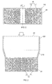
FIG. 2 is a schematic sectional view illustrating a workpiece compact that is formed by a centrifuge in step S2 inFIG. 1 ; -
FIG. 3 is a schematic sectional view illustrating a completed compact formed by a drawing device in step S3 inFIG. 1 ; -
FIG. 4 is a schematic sectional view illustrating the completed compact during a heating treatment in step S4 inFIG. 1 ; -
FIG. 5 is a schematic sectional view illustrating the completed compact at the completion of the heating treatment in step S4; -
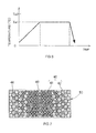
FIG. 6 is a process chart of the heating treatment in step S4 inFIG. 1 ; and -
FIG. 7 is a schematic sectional view illustrating a completed compact after a heating treatment in a second embodiment of the invention. - Hereinafter, a method of manufacturing a magnet according to a first embodiment of the invention will be described in detail with reference to
FIG. 1 to FIG. 6 . First,material powders 10 are compressed into a predetermined shape in a non-heated state. In the present embodiment, acentrifuge 100 is used to compress thematerial powders 10 into the predetermined shape. That is, thematerial powders 10 are charged into the centrifuge 100 (step S1). - In the present embodiment, only hard
magnetic material powders centrifuge 100. The materials that are charged into thecentrifuge 100 do not contain, for example, a bonding agent. A R-Fe-Ne compound that contains a light rare earth element as R, or a Fe-N compound is used for the hardmagnetic material powders magnetic material powders magnetic material powders magnetic material powders 11 having a large average particle diameter and the hardmagnetic material powders 12 having a small average particle diameter are used. Accordingly, the hardmagnetic material powder 11 having a large particle diameter is larger in mass than the hardmagnetic material powder 12 having a small particle diameter. Note that the hardmagnetic material powders - Next, the
centrifuge 100 is driven to form a workpiece compact 20 in an oxidative atmosphere (step S2). The workpiece compact 20 is formed into a disc shape or a cylindrical shape. In the workpiece compact 20, the hardmagnetic material powders FIG. 2 shows an axial sectional view of the workpiece compact 20. As shown inFIG. 2 , by driving thecentrifuge 100, most of the powders having a large mass, on which a large centrifugal force acts, move radially outward, whereas most of the powders having a small mass move radially inward. Because thecentrifuge 100 is used, a through-hole is formed at the center of the workpiece compact 20. - The
powders 10 are in partial contact with each other while gaps are formed between thepowders 10. The workpiece compact 20 is formed in an oxidative atmosphere. Therefore, gas of the oxidative atmosphere enters the gaps between thepowders 10. When the hardmagnetic material powders 11 having a large average particle diameter are located next to each other, the gaps between thepowders 11 are relatively large. On the other hand, the hardmagnetic material powders 12 having a small average particle diameter are located next to each other, the gaps between thepowders 12 are relatively small. Therefore, in the workpiece compact 20, the density of the hard magnetic material in a radially inner side portion is higher than that in a radially outer side portion. - Next, the outer diameter of the workpiece compact 20 is reduced by a
drawing device 200 to fill in the through-hole at the center of the workpiece compact 20. Thus, a completed compact 30 having a disc shape or a cylindrical shape is formed (step S3). Specifically, the workpiece compact 20 is placed at the large diameter side of thedrawing device 200, and is then axially pressurized so as to pass through adiameter reducing portion 210. In this way, the completed compact 30 is formed. As shown inFIG. 3 , mainly the hardmagnetic material powders 11 having a large average particle diameter are arranged in the radially outer side portion, that is, the outer face side portion of the completed compact 30, while mainly the hardmagnetic material powders 12 having a small average particle diameter are arranged in the radially inner side portion, that is, the inside portion of the completed compact 30. Therefore, in the completed compact 30 as well as in the workpiece compact 20, the density of the hard magnetic material in the inside portion is higher than that in the outer face side portion. - Next, the completed compact 30 is heat-treated by microwaves in an oxidative atmosphere (step S4). The heating treatment is as shown in
FIG. 6 . A heating temperature Te1 achieved by the microwaves is set to a value lower than a decomposition temperature Te2 of the hard magnetic material powders 11, 12. For example, when the hard magnetic material powders 11, 12 made of Sm2Fe17N3 or Fe16N2 are used, the decomposition temperature Te2 is approximately 500°C, and therefore the heating temperature Te1 is set lower than 500°C. For example, the heating temperature Te1 is set to approximately 200°C. - Further, as the oxygen content of the oxidative atmosphere, a value that is approximately equal to the oxygen content of the atmospheric is sufficient. Accordingly, the heating treatment may be performed in the atmosphere. If the heating temperature Te1 is set to approximately 200°C, oxide films may be formed in each of the case where Sm2Fe17N3 is used and the case where Fe16N2 is used. The oxide films bond the hard magnetic material powders 11, 12 together. As a result, a magnet having a high bending strength is obtained.
- The heating treatment for the completed compact 30 will be described in detail below. When the hard magnetic material powders 11, 12, which are dielectrics, are irradiated with microwaves, polarization occurs in the hard magnetic material powders 11, 12 irradiated with the microwaves, which causes microwave heating (induction heating by microwaves). The hard magnetic material powders 11, 12 are heated by the microwave heating, and oxide films are formed on the outer faces of the hard magnetic material powders 11, 12. Thus, the hard magnetic material powders 11, 12, which are located next to each other, are bonded to each other by the oxide films formed by the microwave heating.
- Note that polarization occurs more easily as a relative permittivity becomes larger. That is, it is a known fact that the progress of microwave heating is faster in a material having a larger relative permittivity. Further, it is a known fact that the progress of microwave heating is faster as the density of a dielectric is higher.
- Because the hard magnetic material powders 11, 12 that constitute the completed compact 30 are made of the material having the same property, the
powders - The completed compact 30 during the heating treatment is shown in
FIG. 4 , and the completed compact 30 at the completion of the heating treatment is shown inFIG. 5 . As shown inFIG. 4 , during the heating treatment,oxide films 16 are formed on the outer faces of the hard magnetic material powders 12 which are located in the inside portion of the completed compact 30. Accordingly, the hard magnetic material powders 12 that are located in the inside portion of the completed compact 30 are bonded together. At this time, nooxide films 16 have yet been formed in the outer face side portion of the completed compact 30 because the progress of microwave heating is slow in this portion. - By continuing the irradiation of microwaves, as shown in
FIG. 5 , theoxide films 16 are formed not only on the outer faces of the hard magnetic material powders 12 in the inside portion of the completed compact 30 but also on the outer faces of the hard magnetic material powders 11 in the outer face side portion of the completed compact 30. Accordingly, the hard magnetic material powders 11 in the outer face side portion of the completed compact 30 are also bonded together. As stated above, because thepowders 10 are bonded together in the entirety of the completed compact 30 after the heating treatment. Therefore, it is possible to obtain a high bonding force. As a result, it is possible to obtain a high bending strength. - If heating of the
powders 10 progresses earlier in the outer face side portion than in the inside portion and theoxide films 16 are formed earlier in the outer face side portion than in the inside portion, it is difficult for the microwaves to enter the inside portion of the completed compact 30. In some cases, the hard magnetic material powders 11, 12 are brought into partial contact with each other to produce electrical conductivity, and a shield function against the microwaves is fulfilled. In this case, it is difficult for the microwaves to enter the inside portion of the completed compact 30. If the microwave heating progresses from the outer face side portion of the completed compact 30, theoxide films 16 are not easily formed in the inside portion of the completed compact 30. This may cause a possibility that the bonding force in the inside portion of the completed compact 30 will be reduced. - However, as stated above, the rate of progress of the heating by the microwave heating is higher in the inside portion of the completed compact 30. Accordingly, the hard magnetic material powders 12 in the inside portion are reliably bonded together. Moreover, because the microwaves are applied to the outer face side portion of the completed compact 30, the hard magnetic material powders 11 in the outer face side portion of the completed compact 30 are, of course, bonded together by the microwave heating.
- In the above-described embodiment, the
centrifuge 100 is used in order to arrange the hard magnetic material powders 11 having a large particle size in the outer face side portion of the completed compact 30 and to arrange the hard magnetic material powders 12 having a small particle size in the inside portion thereof. This arrangement of thepowders centrifuge 100. However, the invention is not limited to this as long as it is possible to directly arrange thepowders - A second embodiment of the invention will be described below. In the first embodiment, the magnet is manufactured from the hard magnetic material powders 11, 12 that are different in particle size but made of the same kind of compound. The
powders - In the present embodiment, the insulating material of the
powders 42 is, for example, soft ferrite. Soft ferrite is lower in relative permittivity than Sm2Fe17N13 and Fe16N2. The average particle diameter of soft ferrite is determined such that the mass per one particle of soft ferrite is larger than that of the hard magnetic material powders 41. - Further, as in the above-described embodiment, after a workpiece compact is formed with the use of the
centrifuge 100, a completed compact 50 (shown inFIG. 7 ) is formed with the use of thedrawing device 200. The hard magnetic material powders 41 having a small mass per one particle are arranged in the inside portion of the completed compact 50. The insulating material powders 42 having a larger mass per one particle are arranged in the outer face side portion of the completed compact 50. That is, the material having a higher relative permittivity is arranged in the inside portion of the completed compact 50 whereas the material having a lower relative permittivity is arranged in the outer face side portion of the completed compact 50. - When microwaves are applied, polarization due to microwave heating occurs more easily in the material having a higher relative permittivity than in the material having a lower relative permittivity. That is, even when microwaves are applied to the completed compact 50 from the outer face side thereof, the rate of progress of bonding due to the microwave heating is higher in the inside portion of the completed compact 50 than in the outer face side portion thereof. Therefore, the
oxide films 46 are reliably formed in the inside portion of the completed compact 50. By continuously applying microwaves, theoxide films 46 are formed also in the outer face side portion of the completed compact 50. Thus, the material powders 40 are bonded together in the entirety of the completed compact 50. Therefore, it is possible to obtain a high bonding force. As a result, it is possible to obtain a high bending strength. - Further, by setting the relationship between the mass per one particle of the hard magnetic material powders 41 and the mass per one particle of the insulating material powders 42 as stated above, the
powders 41 and thepowders 42 are easily arranged in the inside portion and the outer face side portion of the completed compact 50, respectively, with the use of thecentrifuge 100. Further, by using a soft magnetic material as the material of thepowders 42, a sufficiently high performance as a magnet is fulfilled. - In the above-described embodiment, the insulating material powders 42 are higher in relative permittivity than the above-described hard magnetic material, and are smaller in mass per one particle than the hard magnetic material powders 41. In this case, with the use of the
centrifuge 100, the insulating material powders 42 are arranged in the inside portion of the completed compact 50 whereas the hard magnetic material powders 41 are arranged in the outer peripheral side thereof. In this case as well, because the relative permittivity of the insulating material that is arranged in the inside portion of the completed compact 50 is higher than that of the material arranged in the outer surface portion of the completed compact 50, polarization by the microwave heating reliably progresses from the inside portion of the completed compact 50. As a result, the powders are bonded together in the entirety of the completed compact 50. - When the
powders centrifuge 100, the relationship in mass between thepowders 41 and thepowders 42 is not limited to the one described above. For example, there may be employed a configuration in which a material having a higher relative permittivity is arranged in the inside portion of the completed compact 50 and a material having a lower relative permittivity is arranged in the outer face side portion of the completed compact, irrespective of their masses.
Claims (7)
- A method of manufacturing a magnet from a hard magnetic material formed of material powders made of a R-Fe-N compound containing a light rare earth element as R, or material powders made of a Fe-N compound, the method characterized by comprising:a forming step of forming a compact in which a density of the hard magnetic material powders differs between an outer face side portion and an inside portion of the compact such that a rate of progress of powder bonding due to microwave heating is higher in the inside portion of the compact than in the outer face side portion of the compact when an outer face of the compact is irradiated with microwaves; anda microwave heating step of irradiating the outer face of the compact with the microwaves to cause the microwave heating, thereby bonding the hard magnetic material powders by oxide films that are formed on the hard magnetic material powders.
- The method of manufacturing a magnet according to claim 1, wherein, in the forming step, multiple types of the hard magnetic material powders having different particle sizes are used to form the compact such that the hard magnetic material powders are arranged in the compact such that that the density of the hard magnetic material powders is higher in the inside portion of the compact than in the outer face side portion of the compact.
- The method of manufacturing a magnet according to claim 2, wherein, in the forming step, the compact is formed by using a centrifuge such that the hard magnetic material powders having a smaller particle size are arranged in the inside portion of the compact and the hard magnetic material powders having a larger particle size are arranged in the outer face side portion of the compact.
- A method of manufacturing a magnet from a hard magnetic material formed of material powders made of a R-Fe-N compound containing a light rare earth element as R, or material powders made of a Fe-N compound, and an insulating material formed of insulating material powders, the method characterized by comprising:a forming step of forming a compact from the hard magnetic material and the insulating material that is different in relative permittivity from the hard magnetic material, such that one of the hard magnetic material and the insulating material, which is higher in relative permittivity than the other one of the hard magnetic material and the insulating material, is arranged in an inside portion of the compact and the other one of the hard magnetic material and the insulating material is arranged in an outer surface portion of the compact; anda microwave heating step of irradiating an outer face of the compact with the microwaves to cause microwave heating, thereby bonding the material powders by oxide films that are formed on the material powders.
- The method of manufacturing a magnet according to claim 4, wherein, in the forming step, a centrifuge is used to form the compact such that one of the hard magnetic material and the insulating material, which is higher in relative permittivity and smaller in mass per one particle than the other one of the hard magnetic material and the insulating material, is arranged in the inside portion of the compact and the other one of the hard magnetic material and the insulating material is arranged in the outer surface portion of the compact.
- The method of manufacturing a magnet according to claim 4 or 5, wherein the insulating material is a soft magnetic material.
- A magnet formed from a hard magnetic material formed of material powders made of a R-Fe-N compound containing a light rare earth element as R, or material powders made of a Fe-N compound, characterized in that the magnet is manufactured by forming a compact in which a density of the hard magnetic material powders differs between an outer face side portion and an inside portion of the compact such that a rate of progress of powder bonding due to microwave heating is higher in the inside portion of the compact than in the outer face side portion of the compact when an outer face of the compact is irradiated with microwaves, and irradiating the outer face of the compact with the microwaves to cause the microwave heating, thereby bonding the hard magnetic material powders by oxide films that are formed on the hard magnetic material powders.
Applications Claiming Priority (1)
| Application Number | Priority Date | Filing Date | Title |
|---|---|---|---|
| JP2012040137A JP6003085B2 (en) | 2012-02-27 | 2012-02-27 | Magnet manufacturing method |
Publications (3)
| Publication Number | Publication Date |
|---|---|
| EP2631919A2 true EP2631919A2 (en) | 2013-08-28 |
| EP2631919A3 EP2631919A3 (en) | 2013-12-04 |
| EP2631919B1 EP2631919B1 (en) | 2017-07-05 |
Family
ID=47739164
Family Applications (1)
| Application Number | Title | Priority Date | Filing Date |
|---|---|---|---|
| EP13156393.4A Not-in-force EP2631919B1 (en) | 2012-02-27 | 2013-02-22 | Method of manufacturing magnet |
Country Status (4)
| Country | Link |
|---|---|
| US (1) | US9601246B2 (en) |
| EP (1) | EP2631919B1 (en) |
| JP (1) | JP6003085B2 (en) |
| CN (1) | CN103295760B (en) |
Families Citing this family (1)
| Publication number | Priority date | Publication date | Assignee | Title |
|---|---|---|---|---|
| JP2013175650A (en) * | 2012-02-27 | 2013-09-05 | Jtekt Corp | Magnet manufacturing method and magnet |
Citations (1)
| Publication number | Priority date | Publication date | Assignee | Title |
|---|---|---|---|---|
| JP2009076755A (en) | 2007-09-21 | 2009-04-09 | Seiko Instruments Inc | Method for producing rare earth sintered magnet and method for producing rare earth bonded magnet |
Family Cites Families (38)
| Publication number | Priority date | Publication date | Assignee | Title |
|---|---|---|---|---|
| JPS6054406A (en) | 1983-09-03 | 1985-03-28 | Sumitomo Special Metals Co Ltd | Permanent magnet having excellent oxidation resistance characteristic |
| JPH0734193B2 (en) * | 1985-09-18 | 1995-04-12 | 日本電気株式会社 | Text-separated learning system |
| JPS62206801A (en) | 1986-03-07 | 1987-09-11 | Tohoku Metal Ind Ltd | Manufacture of rare earth magnet |
| JP2791659B2 (en) | 1987-03-06 | 1998-08-27 | 住友特殊金属 株式会社 | Manufacturing method of corrosion resistant permanent magnet |
| JPH0831363B2 (en) | 1987-04-13 | 1996-03-27 | 住友特殊金属株式会社 | Method for manufacturing corrosion-resistant permanent magnet |
| US4942098A (en) | 1987-03-26 | 1990-07-17 | Sumitomo Special Metals, Co., Ltd. | Corrosion resistant permanent magnet |
| JPH04127405A (en) | 1990-09-18 | 1992-04-28 | Kanegafuchi Chem Ind Co Ltd | Highly corrosion-resistant permanent magnet and its manufacture; manufacture of highly corrosion-resistant bonded magnet |
| DE4135122A1 (en) | 1991-10-24 | 1993-04-29 | Vacuumschmelze Gmbh | METHOD FOR PRODUCING A N-CONTAINING PERMANENT MAGNET, LIKE SM2FE17N BY ADDING A SOLID, N-CONTAINING COMPOUND |
| US5762841A (en) * | 1993-07-29 | 1998-06-09 | Toshiba Ceramics Co., Ltd. | Ceramic porous body having a continuous particle size distribution |
| US5886077A (en) * | 1994-12-16 | 1999-03-23 | Matsushita Electric Industrial Co., Ltd. | Rare-earth-iron-nitrogen based magnetic material and method of manufacturing the same |
| JPH1072603A (en) | 1996-09-02 | 1998-03-17 | Toyota Central Res & Dev Lab Inc | Manufacturing method of magnetic material |
| JP2000034503A (en) | 1998-07-17 | 2000-02-02 | Sumitomo Metal Mining Co Ltd | Alloy powder for Sm-Fe-N bonded magnet |
| JP3770734B2 (en) | 1998-09-29 | 2006-04-26 | 日亜化学工業株式会社 | Method for producing Sm-Fe-N alloy powder |
| JP2001076914A (en) * | 1998-12-17 | 2001-03-23 | Sumitomo Special Metals Co Ltd | Rare-earth based permanent magnet and manufacture thereof |
| JP2000208321A (en) | 1999-01-19 | 2000-07-28 | Seiko Precision Inc | Molded plastic magnet molding |
| JP3278647B2 (en) | 1999-01-27 | 2002-04-30 | 住友特殊金属株式会社 | Rare earth bonded magnet |
| JP2002134342A (en) * | 1999-01-27 | 2002-05-10 | Sumitomo Special Metals Co Ltd | Rare-earth permanent magnet and its manufacturing method |
| JP4709340B2 (en) | 1999-05-19 | 2011-06-22 | 株式会社東芝 | Bond magnet manufacturing method and actuator |
| JP3983999B2 (en) * | 2001-05-17 | 2007-09-26 | 日産自動車株式会社 | Manufacturing method of anisotropic exchange spring magnet and motor comprising the same |
| JP2004319602A (en) | 2003-04-11 | 2004-11-11 | Daido Steel Co Ltd | Manufacturing method of isotropic magnet |
| JP2005223263A (en) | 2004-02-09 | 2005-08-18 | Sumitomo Metal Mining Co Ltd | Rare earth permanent magnet manufacturing method and obtained rare earth permanent magnet |
| JP2007039794A (en) | 2005-06-30 | 2007-02-15 | Toyota Motor Corp | Method for producing hard magnetic alloy nanoparticles and method for producing nanocomposite magnets |
| JP2007129105A (en) | 2005-11-04 | 2007-05-24 | Neomax Co Ltd | Rare earth alloy binderless magnet and manufacturing method thereof |
| JP4816146B2 (en) * | 2006-03-03 | 2011-11-16 | パナソニック株式会社 | Sheet-like rare earth bonded magnet, method of manufacturing the same, and motor using the same |
| US7541561B2 (en) * | 2006-09-01 | 2009-06-02 | General Electric Company | Process of microwave heating of powder materials |
| JP2008283141A (en) * | 2007-05-14 | 2008-11-20 | Seiko Instruments Inc | Method for producing rare earth magnet powder and method for producing rare earth bonded magnet |
| US20100261038A1 (en) | 2007-11-02 | 2010-10-14 | Nobuyoshi Imaoka | Composite magnetic material for magnet and method for manufacturing such material |
| WO2010071111A1 (en) | 2008-12-15 | 2010-06-24 | 住友金属鉱山株式会社 | Iron-based magnetic alloy powder containing rare earth element, method for producing same, resin composition for bonded magnet obtained from same, bonded magnet, and compacted magnet |
| JP4961454B2 (en) | 2009-05-12 | 2012-06-27 | 株式会社日立製作所 | Rare earth magnet and motor using the same |
| US20120091832A1 (en) * | 2009-09-21 | 2012-04-19 | Soderberg Rod F | Matrix material comprising magnetic particles for use in hybrid and electric vehicles |
| JP5273012B2 (en) | 2009-10-26 | 2013-08-28 | Tdk株式会社 | Rare earth magnets |
| JP5494056B2 (en) | 2010-03-16 | 2014-05-14 | Tdk株式会社 | Rare earth sintered magnet, rotating machine and reciprocating motor |
| JP4866971B2 (en) | 2010-04-30 | 2012-02-01 | 太陽誘電株式会社 | Coil-type electronic component and manufacturing method thereof |
| CN101870579A (en) * | 2010-06-10 | 2010-10-27 | 上海应用技术学院 | A kind of permanent magnet strontium ferrite material and preparation method thereof |
| JP5165785B2 (en) | 2011-10-19 | 2013-03-21 | 旭化成ケミカルズ株式会社 | Solid material for magnet |
| JP2013175650A (en) | 2012-02-27 | 2013-09-05 | Jtekt Corp | Magnet manufacturing method and magnet |
| JP2014007278A (en) | 2012-06-25 | 2014-01-16 | Jtekt Corp | Method for producing magnet, and magnet |
| US20140374643A1 (en) | 2013-06-25 | 2014-12-25 | Jtekt Corporation | Magnet manufacturing method and magnet |
-
2012
- 2012-02-27 JP JP2012040137A patent/JP6003085B2/en not_active Expired - Fee Related
-
2013
- 2013-02-05 CN CN201310045955.4A patent/CN103295760B/en not_active Expired - Fee Related
- 2013-02-20 US US13/771,887 patent/US9601246B2/en not_active Expired - Fee Related
- 2013-02-22 EP EP13156393.4A patent/EP2631919B1/en not_active Not-in-force
Patent Citations (1)
| Publication number | Priority date | Publication date | Assignee | Title |
|---|---|---|---|---|
| JP2009076755A (en) | 2007-09-21 | 2009-04-09 | Seiko Instruments Inc | Method for producing rare earth sintered magnet and method for producing rare earth bonded magnet |
Also Published As
| Publication number | Publication date |
|---|---|
| CN103295760B (en) | 2016-12-28 |
| CN103295760A (en) | 2013-09-11 |
| EP2631919B1 (en) | 2017-07-05 |
| US20130222093A1 (en) | 2013-08-29 |
| JP2013175651A (en) | 2013-09-05 |
| JP6003085B2 (en) | 2016-10-05 |
| EP2631919A3 (en) | 2013-12-04 |
| US9601246B2 (en) | 2017-03-21 |
Similar Documents
| Publication | Publication Date | Title |
|---|---|---|
| KR101702696B1 (en) | Powder for magnet | |
| JP5870522B2 (en) | Method for manufacturing permanent magnet | |
| EP2608224A1 (en) | Rare earth-iron-nitrogen system alloy material, method for producing rare earth-iron-nitrogen system alloy material, rare earth-iron system alloy material, and method for producing rare earth-iron system alloy material | |
| JP5501828B2 (en) | R-T-B rare earth permanent magnet | |
| CN100498989C (en) | Method for manufacturing radial anisotropic ring magnet | |
| EP3151252A1 (en) | RFeB-BASED MAGNET AND PROCESS FOR PRODUCING RFeB-BASED MAGNET | |
| JP2756471B2 (en) | Method for manufacturing radially oriented magnet and radially oriented magnet | |
| JPH04226003A (en) | Composite soft magnetic material and coated particles for composite soft magnetic material | |
| EP3649659B1 (en) | Method of producing a permanent magnet with inter-grain heavy-rare-earth element | |
| EP2631918A2 (en) | Method of manufacturing magnet and magnet | |
| TW201142878A (en) | Powder for magnet | |
| US11476035B2 (en) | Coil component and method for manufacturing coil component | |
| KR101492449B1 (en) | Method for manufacturing rare earth sintered magnet using pre-sintering process | |
| EP2631919B1 (en) | Method of manufacturing magnet | |
| KR20150131112A (en) | RFeB-BASED MAGNET PRODUCTION METHOD AND RFeB-BASED SINTERED MAGNETS | |
| TWI459419B (en) | Modified neodymium-iron-boron magnet and fabrication method thereof | |
| JP4816146B2 (en) | Sheet-like rare earth bonded magnet, method of manufacturing the same, and motor using the same | |
| EP2980815A1 (en) | Sintered magnet production method | |
| JP2001355006A (en) | Composite structure, method of manufacturing the same, and motor | |
| JPH07161512A (en) | Method for manufacturing radially anisotropic rare earth sintered magnet | |
| JP2006180607A (en) | Sheet-like rare earth bonded magnet, manufacturing method thereof and motor | |
| CN113451029A (en) | Method for producing R-T-B sintered magnet | |
| JP2021527961A (en) | Manufacturing method of magnetic powder | |
| JP5501833B2 (en) | R-T-B permanent magnet | |
| KR102688809B1 (en) | Manufacturing method of rare earth sintered magnet |
Legal Events
| Date | Code | Title | Description |
|---|---|---|---|
| PUAI | Public reference made under article 153(3) epc to a published international application that has entered the european phase |
Free format text: ORIGINAL CODE: 0009012 |
|
| AK | Designated contracting states |
Kind code of ref document: A2 Designated state(s): AL AT BE BG CH CY CZ DE DK EE ES FI FR GB GR HR HU IE IS IT LI LT LU LV MC MK MT NL NO PL PT RO RS SE SI SK SM TR |
|
| AX | Request for extension of the european patent |
Extension state: BA ME |
|
| PUAL | Search report despatched |
Free format text: ORIGINAL CODE: 0009013 |
|
| AK | Designated contracting states |
Kind code of ref document: A3 Designated state(s): AL AT BE BG CH CY CZ DE DK EE ES FI FR GB GR HR HU IE IS IT LI LT LU LV MC MK MT NL NO PL PT RO RS SE SI SK SM TR |
|
| AX | Request for extension of the european patent |
Extension state: BA ME |
|
| RIC1 | Information provided on ipc code assigned before grant |
Ipc: H01F 1/08 20060101ALI20131031BHEP Ipc: H01F 1/059 20060101AFI20131031BHEP Ipc: H01F 1/06 20060101ALI20131031BHEP |
|
| 17P | Request for examination filed |
Effective date: 20140527 |
|
| RBV | Designated contracting states (corrected) |
Designated state(s): AL AT BE BG CH CY CZ DE DK EE ES FI FR GB GR HR HU IE IS IT LI LT LU LV MC MK MT NL NO PL PT RO RS SE SI SK SM TR |
|
| GRAP | Despatch of communication of intention to grant a patent |
Free format text: ORIGINAL CODE: EPIDOSNIGR1 |
|
| INTG | Intention to grant announced |
Effective date: 20170116 |
|
| GRAS | Grant fee paid |
Free format text: ORIGINAL CODE: EPIDOSNIGR3 |
|
| GRAA | (expected) grant |
Free format text: ORIGINAL CODE: 0009210 |
|
| AK | Designated contracting states |
Kind code of ref document: B1 Designated state(s): AL AT BE BG CH CY CZ DE DK EE ES FI FR GB GR HR HU IE IS IT LI LT LU LV MC MK MT NL NO PL PT RO RS SE SI SK SM TR |
|
| REG | Reference to a national code |
Ref country code: GB Ref legal event code: FG4D |
|
| REG | Reference to a national code |
Ref country code: CH Ref legal event code: EP |
|
| REG | Reference to a national code |
Ref country code: AT Ref legal event code: REF Ref document number: 907101 Country of ref document: AT Kind code of ref document: T Effective date: 20170715 |
|
| REG | Reference to a national code |
Ref country code: IE Ref legal event code: FG4D |
|
| REG | Reference to a national code |
Ref country code: DE Ref legal event code: R096 Ref document number: 602013023033 Country of ref document: DE |
|
| REG | Reference to a national code |
Ref country code: NL Ref legal event code: MP Effective date: 20170705 |
|
| REG | Reference to a national code |
Ref country code: AT Ref legal event code: MK05 Ref document number: 907101 Country of ref document: AT Kind code of ref document: T Effective date: 20170705 |
|
| REG | Reference to a national code |
Ref country code: LT Ref legal event code: MG4D |
|
| REG | Reference to a national code |
Ref country code: FR Ref legal event code: PLFP Year of fee payment: 6 |
|
| PG25 | Lapsed in a contracting state [announced via postgrant information from national office to epo] |
Ref country code: AT Free format text: LAPSE BECAUSE OF FAILURE TO SUBMIT A TRANSLATION OF THE DESCRIPTION OR TO PAY THE FEE WITHIN THE PRESCRIBED TIME-LIMIT Effective date: 20170705 Ref country code: LT Free format text: LAPSE BECAUSE OF FAILURE TO SUBMIT A TRANSLATION OF THE DESCRIPTION OR TO PAY THE FEE WITHIN THE PRESCRIBED TIME-LIMIT Effective date: 20170705 Ref country code: HR Free format text: LAPSE BECAUSE OF FAILURE TO SUBMIT A TRANSLATION OF THE DESCRIPTION OR TO PAY THE FEE WITHIN THE PRESCRIBED TIME-LIMIT Effective date: 20170705 Ref country code: FI Free format text: LAPSE BECAUSE OF FAILURE TO SUBMIT A TRANSLATION OF THE DESCRIPTION OR TO PAY THE FEE WITHIN THE PRESCRIBED TIME-LIMIT Effective date: 20170705 Ref country code: SE Free format text: LAPSE BECAUSE OF FAILURE TO SUBMIT A TRANSLATION OF THE DESCRIPTION OR TO PAY THE FEE WITHIN THE PRESCRIBED TIME-LIMIT Effective date: 20170705 Ref country code: NL Free format text: LAPSE BECAUSE OF FAILURE TO SUBMIT A TRANSLATION OF THE DESCRIPTION OR TO PAY THE FEE WITHIN THE PRESCRIBED TIME-LIMIT Effective date: 20170705 Ref country code: NO Free format text: LAPSE BECAUSE OF FAILURE TO SUBMIT A TRANSLATION OF THE DESCRIPTION OR TO PAY THE FEE WITHIN THE PRESCRIBED TIME-LIMIT Effective date: 20171005 |
|
| PG25 | Lapsed in a contracting state [announced via postgrant information from national office to epo] |
Ref country code: BG Free format text: LAPSE BECAUSE OF FAILURE TO SUBMIT A TRANSLATION OF THE DESCRIPTION OR TO PAY THE FEE WITHIN THE PRESCRIBED TIME-LIMIT Effective date: 20171005 Ref country code: RS Free format text: LAPSE BECAUSE OF FAILURE TO SUBMIT A TRANSLATION OF THE DESCRIPTION OR TO PAY THE FEE WITHIN THE PRESCRIBED TIME-LIMIT Effective date: 20170705 Ref country code: ES Free format text: LAPSE BECAUSE OF FAILURE TO SUBMIT A TRANSLATION OF THE DESCRIPTION OR TO PAY THE FEE WITHIN THE PRESCRIBED TIME-LIMIT Effective date: 20170705 Ref country code: PL Free format text: LAPSE BECAUSE OF FAILURE TO SUBMIT A TRANSLATION OF THE DESCRIPTION OR TO PAY THE FEE WITHIN THE PRESCRIBED TIME-LIMIT Effective date: 20170705 Ref country code: LV Free format text: LAPSE BECAUSE OF FAILURE TO SUBMIT A TRANSLATION OF THE DESCRIPTION OR TO PAY THE FEE WITHIN THE PRESCRIBED TIME-LIMIT Effective date: 20170705 Ref country code: GR Free format text: LAPSE BECAUSE OF FAILURE TO SUBMIT A TRANSLATION OF THE DESCRIPTION OR TO PAY THE FEE WITHIN THE PRESCRIBED TIME-LIMIT Effective date: 20171006 Ref country code: IS Free format text: LAPSE BECAUSE OF FAILURE TO SUBMIT A TRANSLATION OF THE DESCRIPTION OR TO PAY THE FEE WITHIN THE PRESCRIBED TIME-LIMIT Effective date: 20171105 |
|
| REG | Reference to a national code |
Ref country code: DE Ref legal event code: R097 Ref document number: 602013023033 Country of ref document: DE |
|
| PG25 | Lapsed in a contracting state [announced via postgrant information from national office to epo] |
Ref country code: RO Free format text: LAPSE BECAUSE OF FAILURE TO SUBMIT A TRANSLATION OF THE DESCRIPTION OR TO PAY THE FEE WITHIN THE PRESCRIBED TIME-LIMIT Effective date: 20170705 Ref country code: DK Free format text: LAPSE BECAUSE OF FAILURE TO SUBMIT A TRANSLATION OF THE DESCRIPTION OR TO PAY THE FEE WITHIN THE PRESCRIBED TIME-LIMIT Effective date: 20170705 Ref country code: CZ Free format text: LAPSE BECAUSE OF FAILURE TO SUBMIT A TRANSLATION OF THE DESCRIPTION OR TO PAY THE FEE WITHIN THE PRESCRIBED TIME-LIMIT Effective date: 20170705 |
|
| PLBE | No opposition filed within time limit |
Free format text: ORIGINAL CODE: 0009261 |
|
| STAA | Information on the status of an ep patent application or granted ep patent |
Free format text: STATUS: NO OPPOSITION FILED WITHIN TIME LIMIT |
|
| PG25 | Lapsed in a contracting state [announced via postgrant information from national office to epo] |
Ref country code: SK Free format text: LAPSE BECAUSE OF FAILURE TO SUBMIT A TRANSLATION OF THE DESCRIPTION OR TO PAY THE FEE WITHIN THE PRESCRIBED TIME-LIMIT Effective date: 20170705 Ref country code: IT Free format text: LAPSE BECAUSE OF FAILURE TO SUBMIT A TRANSLATION OF THE DESCRIPTION OR TO PAY THE FEE WITHIN THE PRESCRIBED TIME-LIMIT Effective date: 20170705 Ref country code: SM Free format text: LAPSE BECAUSE OF FAILURE TO SUBMIT A TRANSLATION OF THE DESCRIPTION OR TO PAY THE FEE WITHIN THE PRESCRIBED TIME-LIMIT Effective date: 20170705 Ref country code: EE Free format text: LAPSE BECAUSE OF FAILURE TO SUBMIT A TRANSLATION OF THE DESCRIPTION OR TO PAY THE FEE WITHIN THE PRESCRIBED TIME-LIMIT Effective date: 20170705 |
|
| 26N | No opposition filed |
Effective date: 20180406 |
|
| PG25 | Lapsed in a contracting state [announced via postgrant information from national office to epo] |
Ref country code: SI Free format text: LAPSE BECAUSE OF FAILURE TO SUBMIT A TRANSLATION OF THE DESCRIPTION OR TO PAY THE FEE WITHIN THE PRESCRIBED TIME-LIMIT Effective date: 20170705 |
|
| REG | Reference to a national code |
Ref country code: CH Ref legal event code: PL |
|
| PG25 | Lapsed in a contracting state [announced via postgrant information from national office to epo] |
Ref country code: MC Free format text: LAPSE BECAUSE OF FAILURE TO SUBMIT A TRANSLATION OF THE DESCRIPTION OR TO PAY THE FEE WITHIN THE PRESCRIBED TIME-LIMIT Effective date: 20170705 |
|
| GBPC | Gb: european patent ceased through non-payment of renewal fee |
Effective date: 20180222 |
|
| REG | Reference to a national code |
Ref country code: IE Ref legal event code: MM4A |
|
| REG | Reference to a national code |
Ref country code: BE Ref legal event code: MM Effective date: 20180228 |
|
| PG25 | Lapsed in a contracting state [announced via postgrant information from national office to epo] |
Ref country code: CH Free format text: LAPSE BECAUSE OF NON-PAYMENT OF DUE FEES Effective date: 20180228 Ref country code: LU Free format text: LAPSE BECAUSE OF NON-PAYMENT OF DUE FEES Effective date: 20180222 Ref country code: LI Free format text: LAPSE BECAUSE OF NON-PAYMENT OF DUE FEES Effective date: 20180228 |
|
| PG25 | Lapsed in a contracting state [announced via postgrant information from national office to epo] |
Ref country code: IE Free format text: LAPSE BECAUSE OF NON-PAYMENT OF DUE FEES Effective date: 20180222 |
|
| PG25 | Lapsed in a contracting state [announced via postgrant information from national office to epo] |
Ref country code: BE Free format text: LAPSE BECAUSE OF NON-PAYMENT OF DUE FEES Effective date: 20180228 Ref country code: GB Free format text: LAPSE BECAUSE OF NON-PAYMENT OF DUE FEES Effective date: 20180222 |
|
| PG25 | Lapsed in a contracting state [announced via postgrant information from national office to epo] |
Ref country code: MT Free format text: LAPSE BECAUSE OF NON-PAYMENT OF DUE FEES Effective date: 20180222 |
|
| PG25 | Lapsed in a contracting state [announced via postgrant information from national office to epo] |
Ref country code: TR Free format text: LAPSE BECAUSE OF FAILURE TO SUBMIT A TRANSLATION OF THE DESCRIPTION OR TO PAY THE FEE WITHIN THE PRESCRIBED TIME-LIMIT Effective date: 20170705 |
|
| PG25 | Lapsed in a contracting state [announced via postgrant information from national office to epo] |
Ref country code: HU Free format text: LAPSE BECAUSE OF FAILURE TO SUBMIT A TRANSLATION OF THE DESCRIPTION OR TO PAY THE FEE WITHIN THE PRESCRIBED TIME-LIMIT; INVALID AB INITIO Effective date: 20130222 Ref country code: PT Free format text: LAPSE BECAUSE OF FAILURE TO SUBMIT A TRANSLATION OF THE DESCRIPTION OR TO PAY THE FEE WITHIN THE PRESCRIBED TIME-LIMIT Effective date: 20170705 |
|
| PG25 | Lapsed in a contracting state [announced via postgrant information from national office to epo] |
Ref country code: MK Free format text: LAPSE BECAUSE OF NON-PAYMENT OF DUE FEES Effective date: 20170705 Ref country code: CY Free format text: LAPSE BECAUSE OF FAILURE TO SUBMIT A TRANSLATION OF THE DESCRIPTION OR TO PAY THE FEE WITHIN THE PRESCRIBED TIME-LIMIT Effective date: 20170705 |
|
| PG25 | Lapsed in a contracting state [announced via postgrant information from national office to epo] |
Ref country code: AL Free format text: LAPSE BECAUSE OF FAILURE TO SUBMIT A TRANSLATION OF THE DESCRIPTION OR TO PAY THE FEE WITHIN THE PRESCRIBED TIME-LIMIT Effective date: 20170705 |
|
| PGFP | Annual fee paid to national office [announced via postgrant information from national office to epo] |
Ref country code: DE Payment date: 20231228 Year of fee payment: 12 |
|
| PGFP | Annual fee paid to national office [announced via postgrant information from national office to epo] |
Ref country code: FR Payment date: 20240103 Year of fee payment: 12 |
|
| REG | Reference to a national code |
Ref country code: DE Ref legal event code: R119 Ref document number: 602013023033 Country of ref document: DE |
|
| PG25 | Lapsed in a contracting state [announced via postgrant information from national office to epo] |
Ref country code: DE Free format text: LAPSE BECAUSE OF NON-PAYMENT OF DUE FEES Effective date: 20250902 |
|
| PG25 | Lapsed in a contracting state [announced via postgrant information from national office to epo] |
Ref country code: FR Free format text: LAPSE BECAUSE OF NON-PAYMENT OF DUE FEES Effective date: 20250228 |