EP2631610A1 - Flow-rate measurement device - Google Patents
Flow-rate measurement device Download PDFInfo
- Publication number
- EP2631610A1 EP2631610A1 EP11834055.3A EP11834055A EP2631610A1 EP 2631610 A1 EP2631610 A1 EP 2631610A1 EP 11834055 A EP11834055 A EP 11834055A EP 2631610 A1 EP2631610 A1 EP 2631610A1
- Authority
- EP
- European Patent Office
- Prior art keywords
- flow
- measurement step
- unit
- rate
- measurement
- Prior art date
- Legal status (The legal status is an assumption and is not a legal conclusion. Google has not performed a legal analysis and makes no representation as to the accuracy of the status listed.)
- Granted
Links
- 238000005259 measurement Methods 0.000 title claims abstract description 334
- 239000012530 fluid Substances 0.000 claims abstract description 147
- 230000005540 biological transmission Effects 0.000 claims abstract description 23
- 230000001902 propagating effect Effects 0.000 claims abstract description 4
- 238000012545 processing Methods 0.000 description 33
- 230000014509 gene expression Effects 0.000 description 29
- 230000010349 pulsation Effects 0.000 description 18
- 238000000034 method Methods 0.000 description 13
- 230000010354 integration Effects 0.000 description 9
- 238000000691 measurement method Methods 0.000 description 5
- 238000010586 diagram Methods 0.000 description 4
- 101150064321 DNTTIP1 gene Proteins 0.000 description 3
- 102100024730 Deoxynucleotidyltransferase terminal-interacting protein 1 Human genes 0.000 description 3
- 238000012935 Averaging Methods 0.000 description 2
- 238000001514 detection method Methods 0.000 description 2
- 230000000737 periodic effect Effects 0.000 description 2
- 230000003252 repetitive effect Effects 0.000 description 2
- 238000011144 upstream manufacturing Methods 0.000 description 2
- 238000012937 correction Methods 0.000 description 1
- 238000002474 experimental method Methods 0.000 description 1
- 239000007788 liquid Substances 0.000 description 1
- 230000004044 response Effects 0.000 description 1
Images
Classifications
-
- G—PHYSICS
- G01—MEASURING; TESTING
- G01F—MEASURING VOLUME, VOLUME FLOW, MASS FLOW OR LIQUID LEVEL; METERING BY VOLUME
- G01F1/00—Measuring the volume flow or mass flow of fluid or fluent solid material wherein the fluid passes through a meter in a continuous flow
- G01F1/66—Measuring the volume flow or mass flow of fluid or fluent solid material wherein the fluid passes through a meter in a continuous flow by measuring frequency, phase shift or propagation time of electromagnetic or other waves, e.g. using ultrasonic flowmeters
- G01F1/667—Arrangements of transducers for ultrasonic flowmeters; Circuits for operating ultrasonic flowmeters
- G01F1/668—Compensating or correcting for variations in velocity of sound
Definitions
- the present invention relates to a flow-rate measurement device which measures the propagation time of an ultrasonic signal to measure the flow rate of a fluid from the flow velocity of the fluid.
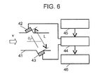
- Fig. 6 is a block diagram of a flow-rate measurement device using a sing-around method of the related art.
- the flow-rate measurement device includes first transducer 42 and second transducer 43 which are provided in fluid path 41, measurement unit 44, control unit 45, and calculation unit 46.
- First transducer 42 which transmits (sends) an ultrasonic wave
- second transducer 43 which receives the transmitted ultrasonic wave are arranged to be opposite to each other in the flow direction of a fluid flowing in fluid path 41.
- Measurement unit 44 measures the propagation time of an ultrasonic wave which propagates between first transducer 42 and second transducer 43.
- Control unit 45 controls measurement unit 44.
- Calculation unit 46 calculates the flow rate of the fluid flowing in the fluid path 41 on the basis of the result of the measurement of measurement unit 44.
- the sound speed is referred to as C
- the flow velocity of the fluid is referred to as v
- the distance between first transducer 42 and second transducer 43 is referred to as L
- the angle between the propagation direction of the ultrasonic wave and the flow direction is referred to as ⁇ .
- the propagation time when an ultrasonic wave is transmitted from first transducer 42 arranged on the upstream side of fluid path 41 and is received by second transducer 43 arranged on the downstream side is referred to as t12.
- the propagation time in the reverse direction of the fluid flow when an ultrasonic wave is transmitted from second transducer 43 arranged on the downstream side of fluid path 41 and is received by first transducer 42 arranged on the upstream side is referred to as t21.
- the propagation time t12 and the reverse propagation time t21 are obtained by the following expressions.
- the cross-sectional area of fluid path 41 is multiplied to the value of the fluid velocity obtained by (Expression 3) to obtain the flow rate of the fluid.
- the term in parentheses of (Expression 3) may be modified as (Expression 4).
- the numerator term of (Expression 4) substantially has a constant value regardless of change in the flow velocity of the fluid
- the numerator term of (Expression 4) substantially has a value proportional to the flow velocity of the fluid.
- measurement unit 44 should have performance so as to execute a measurement, for example, with time resolution of nanosecond (ns) order.
- a flow-rate measurement device in which transmission/reception of an ultrasonic wave is first repetitively executed a plural number of times to repetitively measure the propagation time by measurement unit 44, and the average value of the propagation times measured by measurement unit 44 is obtained, thereby realizing necessary time resolution. That is, if the time resolution of measurement unit 44 is TA and the number of repetitions of the transmission/reception of the ultrasonic wave is M, measurement unit 44 is consecutively operated during a repetitive measurement, and thus the time resolution of the propagation time can be set to TA/M. Therefore, it is possible to realize the measurement of the propagation time with high accuracy when the pressure in fluid path 41 is stable.
- the flow-rate measurement device is applied to, for example, a gas meter which measures the flow rate of gas to be supplied as an energy source to home, there is an inherent problem which is called a pulsation phenomenon.
- the pulsation phenomenon is, for example, the phenomenon in which, as in an air conditioner using a gas engine which is called a GHP (Gas Heat Pump), the pressure in an ambient gas supply pipe fluctuates in synchronization with the rotation of the gas engine.
- a method described in PTL 1 has been suggested.
- the number of repetitions M of the measurement is suppressed to the minimum number of times such that measurement accuracy can be maintained.
- the number of repetition M of the measurement is set as a single measurement unit, a measurement interval is shortened, the measurement unit is executed N times consecutively for a comparatively long time little by little.
- the flow rate is calculated using the results of the measurement consecutively measured the N times, thereby reducing the influence of pulsation.
- the measurement interval is sufficiently shorter than a pressure fluctuation period due to pulsation, it is possible to capture the phase state of the flow-velocity fluctuation waveform of the fluid evenly.
- the measured flow rates are averaged, thereby detecting the real flow velocity (flow rate) of the fluid with the fluctuation component due to pulsation removed.
- a method described in PTL 2 in order to solve the above-described problem, for example, a method described in PTL 2 has been suggested.
- the number of measurements N is controlled in accordance with fluctuation in the flow rate of the fluid.
- a measurement method has been suggested, in which, when the fluctuation in the flow rate of the fluid is small and it can be determined that there is no pulsation, the number of measurements N is reduced, and when fluctuation in the flow rate of the fluid is large and there is pulsation, the number of measurements N increases.
- a flow-rate measurement device of the invention includes a first transducer and a second transducer which are provided in a fluid flow path to transmit and receive an ultrasonic signal, a timer unit which measures a propagation time of the ultrasonic signal propagating between the first transducer and the second transducer, and a flow-rate calculation unit which executes a unit measurement step a predetermined number of times and calculates a flow rate of a fluid flowing in the fluid flow path on the basis of the propagation times measured the predetermined number of times, the unit measurement step being an operation in which a direction of transmission to reception between the first transducer and the second transducer is switched and the timer unit measures the propagation times of the ultrasonic signal in both directions.
- the flow-rate calculation unit measures the flow rate value of the fluid by a precise measurement step in which the unit measurement step is executed a plural number of times to calculate the flow-rate and an exploratory measurement step in which the unit measurement step is executed a smaller number of times than the number of executions in the precise measurement step to calculate the flow rate.
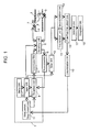
- Fig. 1 is a block diagram of the flow-rate measurement device according to the first exemplary embodiment of the present invention.
- the flow-rate measurement device of this exemplary embodiment includes at least first transducer 2 and second transducer 3 which are provided in fluid flow path 1, switching unit 6 which switches between signals of transmission unit 4 and reception unit 5, measurement control unit 7, first addition unit 13 and second addition unit 14 which integrate the measurement values of timer unit 12, flow-rate calculation unit 15, determination unit 16, selection unit 17, and integration unit 18.
- First transducer 2 which transmits and receives an ultrasonic signal and second transducer 3 which receives and transmits the ultrasonic signal are arranged to be opposite to each other at a predetermined angle ⁇ with respect to the flow direction of a fluid flowing in fluid flow path 1.
- Transmission unit 4 outputs a drive signal to first transducer 2, and first transducer 2 transmits (sends) the ultrasonic signal in response to the drive signal.
- the ultrasonic signal output from first transducer 2 is received by second transducer 3, and the signal received by the second transducer is input to reception unit 5 and subjected to signal processing.
- Switching unit 6 switches the connection of transmission unit 4 and reception unit 5 to first transducer 2 and second transducer 3 to switch the functions of transmission and reception of first transducer 2 and second transducer 3. Accordingly, the transmission and reception of the ultrasonic signal can be performed in first transducer 2 and second transducer 3 in both directions of the forward direction and the reverse direction of the fluid flow, and the measurement of the propagation time can be made by a relational expression described with reference to Fig. 6 .
- Measurement control unit 7 includes at least trigger unit 8, repetition unit 9, delay unit 10, and measurement step control unit 11, and controls the transmission and reception of the ultrasonic signal between first transducer 2 and second transducer 3.
- first transducer 2 and second transducer 3 will be specifically described focusing on a control operation of measurement control unit 7.
- switching unit 6 connects between first transducer 2 and transmission unit 4 and between second transducer 3 and reception unit 5. Accordingly, the measurement of the propagation time is started with first transducer 2 on a transmission side and second transducer 3 on a reception side.
- the above-described connection configuration is referred to as a measurement in "the forward flow direction" and will be described.
- reception unit 5 performs reception processing of the ultrasonic signal. At this time, if the reception processing is performed in reception unit 5 once, a sing-around measurement in "the forward flow direction" is executed with a predetermined number of repetitions set by repetition unit 9 having, for example, a counter or the like.
- a predetermined number of repetitions set by repetition unit 9 having, for example, a counter or the like.
- a predetermined delay time is output from delay unit 10 to trigger unit 8.
- trigger unit 8 When the predetermined delay time has elapsed, trigger unit 8 outputs a transmission and reception switching signal to switching unit 6 to connect between second transducer 3 and transmission unit 4 and between first transducer 2 and reception unit 5. Accordingly, the measurement of the propagation time is started with second transducer 3 on a transmission side and first transducer 2 on a reception side.
- the above-described connection configuration is referred to as a measurement in "the reverse flow direction" and will be described.
- reception unit 5 performs reception processing of the ultrasonic signal.
- reception processing is performed in reception unit 5 once, for example, a sing-around measurement in "the reverse flow direction" is executed a predetermined number of repetitions set by repetition unit 9 having, for example, a counter or the like. Accordingly, the measurement in "the reverse flow direction" in which the functions of transmission and reception of first transducer 2 and second transducer are switched is executed with four repetitions.
- a measurement may be performed once, not in a repetitive manner.
- a measurement may also be performed an arbitrary number of repetitions other than four in accordance with measurement accuracy of a necessary propagation time.
- a sequence of operations in which the sing-around measurement (measurement with four repetitions) in "the forward flow direction", the predetermined delay time, and the sing-around measurement (measurement with four repetitions) in "the reverse flow direction” described above are alternately performed is referred to as a "unit measurement step" and will be described below.
- a first measurement step which is a unit measurement step to be initially executed and a second measurement step comparable to the first measurement step with a predetermined delay time by the output of a delay signal from delay unit 10 are sequentially repeated.
- the above-described operations are repeated up to a final measurement step after a specified number of times through measurement step control unit 11. Accordingly, after the unit measurement step is executed a specified number of times from the first measurement step to the final measurement step, flow-rate calculation unit 15 calculates the flow rate of the fluid.
- timer unit 12 measures the propagation time from the output timing of the trigger signal of trigger unit 8 to the end of the sing-around measurement.
- the propagation time accurately corresponds to the time which is obtained by multiplying the propagation time of the ultrasonic signal between the first transducer and the second transducer by the number of repetitions of the sing-around measurement.
- First addition unit 13 integrates the measurement value of the propagation time of timer unit 12 during the measurement in "the forward flow direction" of each of a specified number of times (for example, N times) of the unit measurement step.
- Second addition unit 14 integrates the measurement value of the propagation time of timer unit 12 during the measurement in "the reverse flow direction" of each of a specified number of times (for example, N times) of the unit measurement step.
- flow-rate calculation unit 15 calculates the flow rate value of the fluid using the output values of the measurement values of the propagation times integrated in first addition unit 13 and second addition unit 14.
- the flow rate value of the fluid to be calculated at this time is the average flow rate of the fluid while the unit measurement steps of the specified N times are executed.
- the unit flow-rate calculation step has two modes having different functions of an exploratory measurement step in which the number of executions of the unit measurement step is small and a precise measurement step in which the number of executions of the unit measurement step is greater than the exploratory measurement step.
- the exploratory measurement step is used for coarse determination on whether or not the fluid flows because the number of executions of the unit measurement step is small while measurement accuracy is low, such that a measurement can end in a short time.
- the precise measurement step is used for calculating the average flow rate of the fluid for every given time or the integrated flow rate of the fluid because measurement accuracy is higher than the exploratory measurement step while the number of executions of the unit measurement step is large.
- Determination unit 16 determines the presence/absence of the flow rate of the fluid in accordance with the output value from flow-rate calculation unit 15 in the exploratory measurement step of the unit flow-rate calculation step, and outputs the determination result to measurement step control unit 11.
- Measurement step control unit 11 controls the operation of the fluid measurement device on the basis of the determination result of determination unit 16. The details will be described below.
- selection unit 17 determines the average flow rate value of the fluid in this period.
- the average flow rate value of the fluid determined by selection unit 17 is output to integration unit 18, and the total usage of the fluid is calculated by integration unit 18.
- a fluid measurement device in which each unit is configured as described above, and the flow rate of the fluid is detected by the operation thereof is realized.
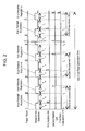
- Fig. 2 is a time chart illustrating the operations of the unit measurement step and the unit flow-rate calculation step of the flow-rate measurement device according to the first exemplary embodiment of the invention.
- the timing of the trigger signal from trigger unit 8 representing the start of the measurement in "the forward flow direction" in the first measurement step serving as an initial unit measurement step as an origin
- the horizontal axis represents an elapsed time
- the vertical axis represents the operation of each unit.
- the measurement in "the forward flow direction" of the first measurement step serving as an initial unit measurement step is executed up to the time t1 in synchronization with the trigger signal.
- a measurement value Td1 of the propagation time in "the forward flow direction" of the first measurement step measured by timer unit 12 is added in first addition unit 13.
- the measurement in "the reverse flow direction" of the first measurement step is started from the time t2 when a predetermined delay time Tint set by delay unit 10 has elapsed, and is executed up to the time t3.
- a measurement value Tu1 of the propagation time in "the reverse flow direction" of the first measurement step measured by timer unit 12 is added in second addition unit 14.
- a measurement value Td2 to a measurement value Tda and a measurement value Tu2 to a measurement value Tua are alternately added in first addition unit 13 and second addition unit 14.
- the measurement value Tda and the measurement value Tua represent the measurements values in the final measurement step corresponding to the a-th measurement step when the unit measurement step has been repeated a times.
- the cross-sectional area of the fluid flow path is multiplied using the total value of the propagation times which are the measurement values of "the forward flow direction" and "the reverse flow direction” added in first addition unit 13 and second addition unit 14, where the flow rate of the fluid is calculated by flow-rate calculation unit 15.
- flow-rate calculation unit 15 obtains a propagation time t12 and a propagation time t21 as an average value per measurement from the measurement values added and held by first addition unit 13 and second addition unit 14.
- a necessary coefficient is multiplied to the obtained flow velocity v to obtain the flow rate value of the fluid.
- the coefficient there are the cross-sectional area of the fluid flow path, a flow-rate correction coefficient for correcting the flow velocity of the fluid to a real average flow velocity, and the like.
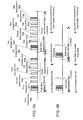
- Fig. 3A is a time chart illustrating the operations of the exploratory measurement step and the precise measurement step of the flow-rate measurement device at the time of the presence of the flow rate according to the first exemplary embodiment of the present invention.
- Fig. 3B is a time chart illustrating the operation of the exploratory measurement step of the flow-rate measurement device at the time of the absence of the flow rate according to the first exemplary embodiment of the present invention.
- each of the unit measurement step, flow-rate calculation processing, and flow-rate presence/absence determination processing shown in Figs. 3A and Fig. 3B is indicated by a rectangle in the drawing as a single processing block, and how a sequence of processing is executed is shown in a time chart.
- Presence of flow rate means that the fluid flow is generated, and the term “absence of flow rate” means that there is no fluid flow.
- the unit flow-rate calculation step is executed by measurement control unit 7 in a given time, for example, with measurement processing of 2 seconds as one section, and the unit flow-rate calculation step is executed once or twice, whereby the flow rate or the like of the fluid is measured.
- the exploratory measurement step having the first measurement step serving as the unit measurement step and the flow-rate calculation processing is executed.
- the unit measurement step is only executed once. For this reason, for example, if the same flow rate is continued, since variation in the measurement result increases, when discriminating slight change in the flow rate of the fluid, it is difficult to execute the measurement with sufficient measurement accuracy. However, it is possible to appropriately set a predetermined value which is a threshold value of the flow rate of the fluid to determine the presence/absence of the fluid flow.
- determination unit 16 performs the flow-rate presence/absence determination processing for determining the presence/absence of the flow rate on the basis of the magnitude relationship between the output result of flow-rate calculation unit 15 and the predetermined value.
- the predetermined value is a value which is specified in accordance with the standard of the flow-rate measurement device or the like, and corresponds to, for example, the flow rate of about 3 L/h.
- measurement control unit 7 executes the precise measurement step.
- the flow rate of the fluid is calculated using the average value of the measurement values measured by the unit measurement steps of 20 times. For this reason, in the precise measurement step, it becomes possible to obtain the flow rate of the fluid with high accuracy compared to, for example, the exploratory measurement step having the single unit measurement step.
- the measurement operation is stopped, thereby reducing power consumption and distributing power to the measurement operation of the precise measurement step which is executed when there is a fluid flow.
- power resources such as a battery.
- flow-rate calculation unit 15 calculates a physical quantity corresponding to the difference in the propagation time using the following (Expression 5) when the exploratory measurement step is executed.
- Tdifl Tul - Tdl
- Tu1 and Td1 in (Expression 5) are defined by the description of Fig. 2 .
- Td1 of (Expression 5) is the integration result of the propagation times of the sing-around measurement in "the forward flow direction” obtained with four repetitions.
- Tu1 of (Expression 5) is the integration result of the propagation times of the sing-around measurement in "the reverse flow direction” obtained with four repetitions.
- Tdif1 of (Expression 5) is obtained as the difference four times greater than the propagation time.
- the value of Tdif1 obtained by (Expression 5) is compared with a predetermined value set in advance on the basis of the result of an experiment or the like, making it possible to determine the presence/absence of the flow rate of the fluid. Therefore, it is possible to determine the presence/absence of the flow rate by executing comparatively simple calculation, thereby reducing power consumption for the following reason.
- the predetermined value is usually determined by the flow rate of the fluid, and in the above-described case, differs in the cross-section of the fluid flow path, the predetermined value corresponds to the time that the fluid flows at the flow rate of 3 L/h.
- the single unit flow-rate calculation step is necessarily executed in a given time (for example, 2 seconds).
- selection unit 17 shown in Fig. 1 outputs one of the flow rate values of "presence of flow rate” and "absence of flow rate” obtained by the unit flow-rate calculation step to integration unit 18 as the average flow rate of the section for the given time (2 seconds).
- the flow rate value of the fluid obtained by flow-rate calculation unit 15 in the precise measurement step is set as the average flow rate of the section for the given time. Therefore, when there is a flow, it is ensured that the flow rate of the fluid is measured with high accuracy.
- the time interval may be random taking into consideration periodic fluctuation in the flow rate of the fluid due to pulsation or the like.
- the time interval is short when the pulsation period is short, and is long when the pulsation period is long. Accordingly, it is possible to suppress the influence of the pulsation phenomenon of the fluid, thereby realizing a measurement with higher accuracy.
- the condition that the single or two unit flow-rate calculation steps are completed in the section for the given time is the same as Figs. 3A and 3B .
- the condition that the time interval is random means the time interval from the start point of the section to the start time of the initial exploratory measurement step when the time interval of the section of the single unit flow-rate calculation step is fixed to 2 seconds.
- the flow-rate measurement device of the present invention includes the determination unit which determines the presence/absence of the flow rate of the fluid from the magnitude of the flow rate value obtained by the exploratory measurement step of the unit flow-rate calculation step, wherein, only when the determination unit determines to be the presence of the flow rate, the precise measurement step is executed. For this reason, when it is determined that there is no fluid flow, the measurement operation is stopped, thereby reducing power consumption and distributing power to the measurement operation of the precise measurement step which is executed when there is a fluid flow. As a result, it is possible to effectively use a limited amount of power resources of, for example, a battery or the like.
- the flow-rate calculation unit calculates the difference between the propagation times in both directions of "the forward flow direction” and "the reverse flow direction” to determine the flow rate of the fluid in the exploratory measurement step.
- the determination unit determines to be the absence of the flow rate, and the calculation of the flow rate is omitted. Therefore, in the determination on the presence/absence of the flow rate of the fluid, it is possible to reduce the number of executions of multiplication/division having a long calculation processing time of a calculation processing unit, thereby reducing power consumption.
- the predetermined value is usually determined by the flow rate of the fluid, and in the above-described case, differs in the cross-section of the fluid flow path, for example, the predetermined value corresponds to the time that the fluid flows at the flow rate of 3 L/h.
- the determination unit determines that there is no fluid flow
- the output of the flow-rate calculation unit is set to zero such that the processing for calculating the flow rate is not performed, it is possible to further reduce power consumption when there is no flow.
- processing for enabling a power saving mode such as sleep
- up to the start of the next section alter the processing for calculating the flow rate, if the calculation processing is not performed, it is possible to suppress power consumption as much.
- the selection unit selects the flow rate value obtained in the precise measurement step as the average flow rate value of the fluid. As a result, it is possible to measure the flow rate of the fluid with high accuracy when there is a fluid flow.
- the overall configuration of the fluid measurement device of this exemplary embodiment is the same as Fig. 1 shown in the first exemplary embodiment. Since the operation of the unit flow-rate calculation step is the same as the first exemplary embodiment described with reference to Fig. 2 , detailed description will not be repeated.
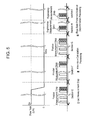
- this exemplary embodiment is different from the first exemplary embodiment in that the operation to switch between the exploratory measurement step and the precise measurement step in the measurements of "presence of flow rate" of Fig. 3A and "absence of flow rate” of Fig. 3B is different, and will be specifically described with reference to Figs. 4 and 5 .
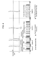
- Fig. 4 is a time chart illustrating the operation to switch between the exploratory measurement step and the precise measurement step in the flow-rate measurement device according to the second exemplary embodiment of the present invention.
- Fig. 5 is another time chart illustrating the operation to switch between the exploratory measurement step and the precise measurement step of the flow-rate measurement device according to the second exemplary embodiment of the present invention.
- FIGs. 4 and 5 illustrate the relationship between the flow rate of the fluid and the switching between the measurement steps in a comparison manner.
- Sections A to I shown in the drawings represent the unit flow-rate calculation step with a section width for a given time (for example, 2 seconds). The average flow rate and the integrated flow rate of the fluid are measured and updated for each section.
- the determination result of the determination unit 16 becomes "absence of flow rate". For this reason, in the section A and the section B, as in the first exemplary embodiment, the operation of the precise measurement step is omitted.
- the operation of the exploratory measurement step can be omitted in subsequent sections, making it possible to reduce power consumption.
- determination unit 16 determines to the "absence of flow rate".
- the operation of the exploratory measurement step is restarted from the next section H.
- the predetermined value is a value which is specified in accordance with the standard of the flow-rate measurement device or the like, and corresponds to, for example, the flow rate of 3 L/h.
- the determination condition of "absence of flow rate" in the calculation of the flow rate an example where a value equal to or smaller than a predetermined value is detected consecutively two times has been described, the invention is not limited thereto.
- the condition that the number of times of the detection is two is to increase the reliability for the determination of "absence of flow rate", it is obvious that the number of times of the detection is not limited to two. For example, the determination may be only made once.
- the time interval may be random taking into consideration periodic fluctuation in the flow rate of the fluid due to pulsation or the like. Accordingly, it is possible to suppress the influence of the pulsation phenomenon of the fluid, thereby realizing a measurement with higher accuracy.
- the condition that the single or two unit flow-rate calculation steps are completed in the section for the given time is the same as Figs. 4 and 5 .
- the condition that the time interval is random means the time interval from the start point of the section to the start time of the initial exploratory measurement step when the time interval of the section of the single unit flow-rate calculation step is fixed to 2 seconds is arbitrary.
- the operation of the exploratory measurement step can be restarted by the operation shown in Fig. 5 to measure the flow rate. Therefore, it is possible to appropriately switch between the exploratory measurement step and the precise measurement step in accordance with, for example, the flow rate of the fluid depending on the usage of gas or the like, thereby measuring the flow rate. As a result, it is possible to realize a flow-rate measurement device which stably operates over a long period of time effectively using a limited amount of power resources of a battery or the like.
- Fig. 4 after the measurement by the precise measurement step has been started, the execution of the exploratory measurement step is stopped, and as shown in Fig. 5 , when the result of the measurement by the precise measurement step is smaller than a predetermined flow rate value, the execution of the exploratory measurement step is restarted.
- a flow-rate measurement device which can measure the flow rate while appropriately switching a measurement method in accordance with the presence/absence of the flow rate.
- a flow-rate measurement device includes a first transducer and a second transducer which are provided in a fluid flow path to transmit and receive an ultrasonic signal, a timer unit which measures a propagation time of the ultrasonic signal propagating between the first transducer and the second transducer, and a flow-rate calculation unit which executes a unit measurement step a predetermined number of times and calculates a flow rate of a fluid flowing in the fluid flow path on the basis of the propagation times measured the predetermined number of times, the unit measurement step being an operation in which a direction of transmission to reception between the first transducer and the second transducer is switched and the timer unit measures the propagation times of the ultrasonic signal in both directions.
- the flow-rate calculation unit measures a flow rate value of the fluid by a precise measurement step in which the unit measurement step is executed a plural number of times to calculate the flow-rate and an exploratory measurement step in which the unit measurement step is executed a smaller number of times than the number of executions in the precise measurement step to calculate the flow rate. Therefore, it is possible to efficiently detect the presence/absence of the fluid flow. As a result, when there is no fluid flow, power consumption is reduced, and when there is a flow, power is used with concentration, thereby realizing a flow-rate measurement device which effectively distributes a limited amount of power resources.
- the precise measurement step is executed only when the flow rate value of the fluid obtained in the exploratory measurement step is equal to or greater than a predetermined value. Therefore, it is possible to effectively reduce power consumption when there is no fluid flow.
- the precise measurement step is executed only when a difference between the propagation times in both directions detected in the exploratory measurement step is equal to or greater than a predetermined value. Therefore, when determining the presence/absence of the flow rate, the number of executions of multiplication/division with a long calculation processing time is reduced, thereby reducing power consumption.
- the flow-rate measurement device further includes a selection unit selects the calculated flow rate value as an average flow rate within the given time by executing either the exploratory measurement step or the precise measurement step at least once within a given time, and calculating the flow rate value of the fluid, wherein, when the precise measurement step has been executed, the selection unit selects the flow rate value of the fluid obtained in the precise measurement step. Therefore, when there is a fluid flow, it is possible to measure the flow velocity of the fluid with high accuracy.
- the present invention can be applied to a wide field including not only a gas meter but also a gas flow meter or a liquid flow meter.
Landscapes
- Physics & Mathematics (AREA)
- Electromagnetism (AREA)
- Fluid Mechanics (AREA)
- General Physics & Mathematics (AREA)
- Measuring Volume Flow (AREA)
Abstract
Description
- The present invention relates to a flow-rate measurement device which measures the propagation time of an ultrasonic signal to measure the flow rate of a fluid from the flow velocity of the fluid.
- In the related art, a flow-rate measurement device using a so-called sing-around method, which repeats transmission/reception between two transducers multiple times to increase measurement resolution, has been suggested.
- Hereinafter, an example of a flow-rate measurement device of the related art which is applied to a household gas meter will be described with reference to
Fig. 6 . -
Fig. 6 is a block diagram of a flow-rate measurement device using a sing-around method of the related art. As shown inFig. 6 , the flow-rate measurement device includesfirst transducer 42 andsecond transducer 43 which are provided influid path 41,measurement unit 44,control unit 45, andcalculation unit 46.First transducer 42 which transmits (sends) an ultrasonic wave andsecond transducer 43 which receives the transmitted ultrasonic wave are arranged to be opposite to each other in the flow direction of a fluid flowing influid path 41.Measurement unit 44 measures the propagation time of an ultrasonic wave which propagates betweenfirst transducer 42 andsecond transducer 43.Control unit 45controls measurement unit 44.Calculation unit 46 calculates the flow rate of the fluid flowing in thefluid path 41 on the basis of the result of the measurement ofmeasurement unit 44. - Hereinafter, a method which calculates the flow rate of the fluid flowing in
fluid path 41 will be described. As shown inFig. 6 , the sound speed is referred to as C, the flow velocity of the fluid is referred to as v, the distance betweenfirst transducer 42 andsecond transducer 43 is referred to as L, and the angle between the propagation direction of the ultrasonic wave and the flow direction is referred to as θ. - The propagation time when an ultrasonic wave is transmitted from
first transducer 42 arranged on the upstream side offluid path 41 and is received bysecond transducer 43 arranged on the downstream side is referred to as t12. The propagation time in the reverse direction of the fluid flow when an ultrasonic wave is transmitted fromsecond transducer 43 arranged on the downstream side offluid path 41 and is received byfirst transducer 42 arranged on the upstream side is referred to as t21. - At this time, the propagation time t12 and the reverse propagation time t21 are obtained by the following expressions.


- Next, if (Expression 1) and (Expression 2) are modified, the flow velocity v of the fluid is obtained from (Expression 3).

- The cross-sectional area of
fluid path 41 is multiplied to the value of the fluid velocity obtained by (Expression 3) to obtain the flow rate of the fluid. At this time, the term in parentheses of (Expression 3) may be modified as (Expression 4).
- While the denominator term of (Expression 4) substantially has a constant value regardless of change in the flow velocity of the fluid, the numerator term of (Expression 4) substantially has a value proportional to the flow velocity of the fluid.
- Accordingly, in order to accurately measure the flow velocity of the fluid, it is necessary to measure the difference between the propagation time t12 and the reverse propagation time t21 with satisfactory accuracy. That is, it is necessary to obtain a minute difference in the propagation time as the flow velocity of the fluid becomes lower. For this reason, when measuring the difference between the propagation time t12 and the reverse propagation time t21 singly,
measurement unit 44 should have performance so as to execute a measurement, for example, with time resolution of nanosecond (ns) order. - However, it is usually difficult to realize time resolution of nanosecond (ns) order. For example, even if the time resolution of nanosecond (ns) order is realized, there is a problem in which power consumption increases due to high-speed processing.
- Accordingly, in order to solve the above-described problem, usually, a flow-rate measurement device has been developed in which transmission/reception of an ultrasonic wave is first repetitively executed a plural number of times to repetitively measure the propagation time by
measurement unit 44, and the average value of the propagation times measured bymeasurement unit 44 is obtained, thereby realizing necessary time resolution. That is, if the time resolution ofmeasurement unit 44 is TA and the number of repetitions of the transmission/reception of the ultrasonic wave is M,measurement unit 44 is consecutively operated during a repetitive measurement, and thus the time resolution of the propagation time can be set to TA/M. Therefore, it is possible to realize the measurement of the propagation time with high accuracy when the pressure influid path 41 is stable. - However, when the flow-rate measurement device is applied to, for example, a gas meter which measures the flow rate of gas to be supplied as an energy source to home, there is an inherent problem which is called a pulsation phenomenon. The pulsation phenomenon is, for example, the phenomenon in which, as in an air conditioner using a gas engine which is called a GHP (Gas Heat Pump), the pressure in an ambient gas supply pipe fluctuates in synchronization with the rotation of the gas engine.
- When the pulsation phenomenon occurs, even if a gas appliance is not used, gas moves in the gas supply pipe in synchronization with fluctuation in pressure. As a result, there is a problem in that the flow-rate measurement device detects the flow rate as if gas flows in the gas supply pipe.
- Accordingly, as a method which suppresses the influence of the pulsation phenomenon, for example, a method described in
PTL 1 has been suggested. According to the method ofPTL 1, first, the number of repetitions M of the measurement is suppressed to the minimum number of times such that measurement accuracy can be maintained. Next, the number of repetition M of the measurement is set as a single measurement unit, a measurement interval is shortened, the measurement unit is executed N times consecutively for a comparatively long time little by little. The flow rate is calculated using the results of the measurement consecutively measured the N times, thereby reducing the influence of pulsation. At this time, in particular, if the measurement interval is sufficiently shorter than a pressure fluctuation period due to pulsation, it is possible to capture the phase state of the flow-velocity fluctuation waveform of the fluid evenly. The measured flow rates are averaged, thereby detecting the real flow velocity (flow rate) of the fluid with the fluctuation component due to pulsation removed. - However, when the above-described measurement method is constantly continued, while the influence of pulsation can be reduced, there is a problem in that power consumption increases.
- Accordingly, in order to solve the above-described problem, for example, a method described in
PTL 2 has been suggested. According to the method ofPTL 2, in order to reduce power consumption, the number of measurements N is controlled in accordance with fluctuation in the flow rate of the fluid. Specifically, a measurement method has been suggested, in which, when the fluctuation in the flow rate of the fluid is small and it can be determined that there is no pulsation, the number of measurements N is reduced, and when fluctuation in the flow rate of the fluid is large and there is pulsation, the number of measurements N increases. - In the configuration of
PTL 2, however, when pulsation does not occur, while power consumption can be reduced, there is no disclosure about a measurement method which reduces power consumption according to the magnitude of the flow rate of the fluid. - That is, for example, as in a gas meter which has a battery or the like as a drive source, in order to effectively use a limited amount of power resources, first, when there is no pulsation, power consumption is suppressed. When there is no influence on an integrated flow rate, that is, there is no fluid flow, there is a need for a method which suppresses the frequency of the flow-rate measurement operation, thereby reducing power consumption of the entire flow-rate measurement device.
-
- PTL 1: Japanese Patent Unexamined Publication No.
2002-350202 - PTL 2: Japanese Patent No.
3427839 - A flow-rate measurement device of the invention includes a first transducer and a second transducer which are provided in a fluid flow path to transmit and receive an ultrasonic signal, a timer unit which measures a propagation time of the ultrasonic signal propagating between the first transducer and the second transducer, and a flow-rate calculation unit which executes a unit measurement step a predetermined number of times and calculates a flow rate of a fluid flowing in the fluid flow path on the basis of the propagation times measured the predetermined number of times, the unit measurement step being an operation in which a direction of transmission to reception between the first transducer and the second transducer is switched and the timer unit measures the propagation times of the ultrasonic signal in both directions. The flow-rate calculation unit measures the flow rate value of the fluid by a precise measurement step in which the unit measurement step is executed a plural number of times to calculate the flow-rate and an exploratory measurement step in which the unit measurement step is executed a smaller number of times than the number of executions in the precise measurement step to calculate the flow rate.
- Therefore, it is possible to efficiently detect the presence/absence of the fluid flow. As a result, when there is no fluid flow, power consumption is reduced, and when there is a flow, power is used with concentration, thereby realizing a flow-rate measurement device which effectively distributes a limited amount of power resources.
-
-
Fig. 1 is a block diagram of a flow-rate measurement device according to a first exemplary embodiment of the present invention. -
Fig. 2 is a time chart illustrating operations of a unit measurement step and a unit flow-rate calculation step of the flow-rate measurement device according to the first exemplary embodiment of the present invention. -
Fig. 3A is a time chart illustrating operations of an exploratory measurement step and a precise measurement step of a flow-rate measurement device at the time of the presence of a flow rate according to an exemplary embodiment of the present invention. -
Fig. 3B is a time chart illustrating an operation of an exploratory measurement step of a flow-rate measurement device at the time of the absence of a flow rate according to an exemplary embodiment of the present invention. -
Fig. 4 is a time chart illustrating an operation to switch between an exploratory measurement step and a precise measurement step of a flow-rate measurement device according to a second exemplary embodiment of the present invention. -
Fig. 5 is another time chart illustrating an operation to switch between an exploratory measurement step and a precise measurement step of the flow-rate measurement device according to the second exemplary embodiment of the present invention. -
Fig. 6 is a block diagram of a flow-rate measurement device which uses a sing-around method of the related art. - Hereinafter, exemplary embodiments of the present invention will be described with reference to the drawings. It should be noted that the present invention is not limited to the exemplary embodiments.
- Hereinafter, a fluid measurement device according to a first exemplary embodiment of the present invention will be described with reference to
Fig. 1 . -
Fig. 1 is a block diagram of the flow-rate measurement device according to the first exemplary embodiment of the present invention. - As shown in
Fig. 1 , the flow-rate measurement device of this exemplary embodiment includes at leastfirst transducer 2 and second transducer 3 which are provided influid flow path 1, switchingunit 6 which switches between signals oftransmission unit 4 andreception unit 5,measurement control unit 7,first addition unit 13 andsecond addition unit 14 which integrate the measurement values oftimer unit 12, flow-rate calculation unit 15,determination unit 16,selection unit 17, andintegration unit 18. -
First transducer 2 which transmits and receives an ultrasonic signal and second transducer 3 which receives and transmits the ultrasonic signal are arranged to be opposite to each other at a predetermined angle θ with respect to the flow direction of a fluid flowing influid flow path 1.Transmission unit 4 outputs a drive signal tofirst transducer 2, andfirst transducer 2 transmits (sends) the ultrasonic signal in response to the drive signal. The ultrasonic signal output fromfirst transducer 2 is received by second transducer 3, and the signal received by the second transducer is input toreception unit 5 and subjected to signal processing.Switching unit 6 switches the connection oftransmission unit 4 andreception unit 5 tofirst transducer 2 and second transducer 3 to switch the functions of transmission and reception offirst transducer 2 and second transducer 3. Accordingly, the transmission and reception of the ultrasonic signal can be performed infirst transducer 2 and second transducer 3 in both directions of the forward direction and the reverse direction of the fluid flow, and the measurement of the propagation time can be made by a relational expression described with reference toFig. 6 . -
Measurement control unit 7 includes atleast trigger unit 8,repetition unit 9,delay unit 10, and measurementstep control unit 11, and controls the transmission and reception of the ultrasonic signal betweenfirst transducer 2 and second transducer 3. - Hereinafter, the operations of the transmission and reception of
first transducer 2 and second transducer 3 will be specifically described focusing on a control operation ofmeasurement control unit 7. - First, as shown in
Fig. 1 , if a trigger signal to start a measurement is output fromtrigger unit 8 to switchingunit 6, switchingunit 6 connects betweenfirst transducer 2 andtransmission unit 4 and between second transducer 3 andreception unit 5. Accordingly, the measurement of the propagation time is started withfirst transducer 2 on a transmission side and second transducer 3 on a reception side. Hereinafter, the above-described connection configuration is referred to as a measurement in "the forward flow direction" and will be described. - Next, if a drive signal is output from
transmission unit 4 tofirst transducer 2, an ultrasonic signal is output fromfirst transducer 2. If the output ultrasonic signal reaches second transducer 3 and is received,reception unit 5 performs reception processing of the ultrasonic signal. At this time, if the reception processing is performed inreception unit 5 once, a sing-around measurement in "the forward flow direction" is executed with a predetermined number of repetitions set byrepetition unit 9 having, for example, a counter or the like. Hereinafter, an example where the predetermined number of repetitions is 4 will be described. - Next, if the sing-around measurement in "the forward flow direction" with four repetitions is completed, a predetermined delay time is output from
delay unit 10 to triggerunit 8. When the predetermined delay time has elapsed,trigger unit 8 outputs a transmission and reception switching signal to switchingunit 6 to connect between second transducer 3 andtransmission unit 4 and betweenfirst transducer 2 andreception unit 5. Accordingly, the measurement of the propagation time is started with second transducer 3 on a transmission side andfirst transducer 2 on a reception side. Hereinafter, the above-described connection configuration is referred to as a measurement in "the reverse flow direction" and will be described. - Next, in the above-described connection state, if a trigger signal to start a measurement is output from
trigger unit 8 to switchingunit 6, a drive signal is output fromtransmission unit 4 to second transducer 3, and an ultrasonic signal is output from second transducer 3. If the output ultrasonic signal reachesfirst transducer 2 and is received,reception unit 5 performs reception processing of the ultrasonic signal. At this time, if the reception processing is performed inreception unit 5 once, for example, a sing-around measurement in "the reverse flow direction" is executed a predetermined number of repetitions set byrepetition unit 9 having, for example, a counter or the like. Accordingly, the measurement in "the reverse flow direction" in which the functions of transmission and reception offirst transducer 2 and second transducer are switched is executed with four repetitions. - Although in this exemplary embodiment, an example where the number of repetitions is 4 has been described, the present invention is not limited thereto. For example, if the time resolution of
timer unit 12 described below is sufficiently secured, a measurement may be performed once, not in a repetitive manner. A measurement may also be performed an arbitrary number of repetitions other than four in accordance with measurement accuracy of a necessary propagation time. - A sequence of operations in which the sing-around measurement (measurement with four repetitions) in "the forward flow direction", the predetermined delay time, and the sing-around measurement (measurement with four repetitions) in "the reverse flow direction" described above are alternately performed is referred to as a "unit measurement step" and will be described below.
- Next, as will be described below in detail with reference to
Fig. 2 , the operations of a first measurement step which is a unit measurement step to be initially executed and a second measurement step comparable to the first measurement step with a predetermined delay time by the output of a delay signal fromdelay unit 10 are sequentially repeated. The above-described operations are repeated up to a final measurement step after a specified number of times through measurementstep control unit 11. Accordingly, after the unit measurement step is executed a specified number of times from the first measurement step to the final measurement step, flow-rate calculation unit 15 calculates the flow rate of the fluid. - At this time,
timer unit 12 measures the propagation time from the output timing of the trigger signal oftrigger unit 8 to the end of the sing-around measurement. The propagation time accurately corresponds to the time which is obtained by multiplying the propagation time of the ultrasonic signal between the first transducer and the second transducer by the number of repetitions of the sing-around measurement. -
First addition unit 13 integrates the measurement value of the propagation time oftimer unit 12 during the measurement in "the forward flow direction" of each of a specified number of times (for example, N times) of the unit measurement step.Second addition unit 14 integrates the measurement value of the propagation time oftimer unit 12 during the measurement in "the reverse flow direction" of each of a specified number of times (for example, N times) of the unit measurement step. - Next, if the operation of the unit measurement steps of the specified N times is completed, flow-
rate calculation unit 15 calculates the flow rate value of the fluid using the output values of the measurement values of the propagation times integrated infirst addition unit 13 andsecond addition unit 14. The flow rate value of the fluid to be calculated at this time is the average flow rate of the fluid while the unit measurement steps of the specified N times are executed. - Hereinafter, a sequence of operations including the first measurement step described above, the operation to the N-th measurement step which is the final measurement step corresponding to a case where the measurement step is repeated N times, and then flow-
rate calculation unit 15 which calculates the flow rate of the fluid is referred to as a "unit flow-rate calculation step" and will be described. - The unit flow-rate calculation step has two modes having different functions of an exploratory measurement step in which the number of executions of the unit measurement step is small and a precise measurement step in which the number of executions of the unit measurement step is greater than the exploratory measurement step.
- The exploratory measurement step is used for coarse determination on whether or not the fluid flows because the number of executions of the unit measurement step is small while measurement accuracy is low, such that a measurement can end in a short time. The precise measurement step is used for calculating the average flow rate of the fluid for every given time or the integrated flow rate of the fluid because measurement accuracy is higher than the exploratory measurement step while the number of executions of the unit measurement step is large.
-
Determination unit 16 determines the presence/absence of the flow rate of the fluid in accordance with the output value from flow-rate calculation unit 15 in the exploratory measurement step of the unit flow-rate calculation step, and outputs the determination result to measurementstep control unit 11. Measurementstep control unit 11 controls the operation of the fluid measurement device on the basis of the determination result ofdetermination unit 16. The details will be described below. - On the basis of the calculation result of the flow rate of flow-
rate calculation unit 15 which is executed in a given period (a given time),selection unit 17 determines the average flow rate value of the fluid in this period. The average flow rate value of the fluid determined byselection unit 17 is output tointegration unit 18, and the total usage of the fluid is calculated byintegration unit 18. - A fluid measurement device in which each unit is configured as described above, and the flow rate of the fluid is detected by the operation thereof is realized.
- Hereinafter, the flow of the operation of each unit in the unit measurement step and the unit flow-rate calculation step described above will be specifically described with reference to
Fig. 2 . -
Fig. 2 is a time chart illustrating the operations of the unit measurement step and the unit flow-rate calculation step of the flow-rate measurement device according to the first exemplary embodiment of the invention. InFig. 2 , with the timing of the trigger signal fromtrigger unit 8 representing the start of the measurement in "the forward flow direction" in the first measurement step serving as an initial unit measurement step as an origin, the horizontal axis represents an elapsed time, and the vertical axis represents the operation of each unit. - As shown in
Fig. 2 , first, the measurement in "the forward flow direction" of the first measurement step serving as an initial unit measurement step is executed up to the time t1 in synchronization with the trigger signal. At the time t1 of the first measurement step, a measurement value Td1 of the propagation time in "the forward flow direction" of the first measurement step measured bytimer unit 12 is added infirst addition unit 13. - Next, the measurement in "the reverse flow direction" of the first measurement step is started from the time t2 when a predetermined delay time Tint set by
delay unit 10 has elapsed, and is executed up to the time t3. At the time t3 of the first measurement step, a measurement value Tu1 of the propagation time in "the reverse flow direction" of the first measurement step measured bytimer unit 12 is added insecond addition unit 14. - Thereafter, when the predetermined delay time Tint set by
delay unit 10 has elapsed, the second measurement step is started. - After the second measurement step, similarly, each time the measurements in "the forward flow direction" and "the reverse flow direction" end, for example, a measurement value Td2 to a measurement value Tda and a measurement value Tu2 to a measurement value Tua are alternately added in
first addition unit 13 andsecond addition unit 14. The measurement value Tda and the measurement value Tua represent the measurements values in the final measurement step corresponding to the a-th measurement step when the unit measurement step has been repeated a times. - Next, at the time td at which the unit measurement steps of a given number of times (in the above description, a times) end, the cross-sectional area of the fluid flow path is multiplied using the total value of the propagation times which are the measurement values of "the forward flow direction" and "the reverse flow direction" added in
first addition unit 13 andsecond addition unit 14, where the flow rate of the fluid is calculated by flow-rate calculation unit 15. - Hereinafter, a method of calculating the flow rate of the fluid which is performed by flow-
rate calculation unit 15 will be specifically described. - First, flow-
rate calculation unit 15 obtains a propagation time t12 and a propagation time t21 as an average value per measurement from the measurement values added and held byfirst addition unit 13 andsecond addition unit 14. - Next, the flow velocity v of the fluid is obtained using (Expression 3) described in the background art.
- A necessary coefficient is multiplied to the obtained flow velocity v to obtain the flow rate value of the fluid. At this time, as the coefficient, there are the cross-sectional area of the fluid flow path, a flow-rate correction coefficient for correcting the flow velocity of the fluid to a real average flow velocity, and the like.
- That is, the time interval shown in
Fig. 2 from the time t=0 to the time td at which the flow rate is calculated corresponds to the unit flow-rate calculation step. - Hereinafter, the relationship between the precise measurement step and the exploratory measurement step constituting the unit flow-rate calculation step will be described with reference to
Figs. 3A and 3B in addition toFig. 1 while comparing "presence of flow rate" and "absence of flow rate". -
Fig. 3A is a time chart illustrating the operations of the exploratory measurement step and the precise measurement step of the flow-rate measurement device at the time of the presence of the flow rate according to the first exemplary embodiment of the present invention.Fig. 3B is a time chart illustrating the operation of the exploratory measurement step of the flow-rate measurement device at the time of the absence of the flow rate according to the first exemplary embodiment of the present invention. Specifically, each of the unit measurement step, flow-rate calculation processing, and flow-rate presence/absence determination processing shown inFigs. 3A and Fig. 3B is indicated by a rectangle in the drawing as a single processing block, and how a sequence of processing is executed is shown in a time chart. - The term "presence of flow rate" means that the fluid flow is generated, and the term "absence of flow rate" means that there is no fluid flow.
- Although in
Figs. 3A and 3B , a case whether N=1 in the exploratory measurement step and N=20 in the precise measurement step as an example of the number of executions (number of repetitions) N of the unit measurement step has been described, the present invention is not limited thereto. - As shown in
Figs. 3A and 3B , the unit flow-rate calculation step is executed bymeasurement control unit 7 in a given time, for example, with measurement processing of 2 seconds as one section, and the unit flow-rate calculation step is executed once or twice, whereby the flow rate or the like of the fluid is measured. - At the head of the measurement period (given time) shown in
Figs. 3A and 3B , first, the exploratory measurement step having the first measurement step serving as the unit measurement step and the flow-rate calculation processing is executed. - At this time, in the exploratory measurement step, the unit measurement step is only executed once. For this reason, for example, if the same flow rate is continued, since variation in the measurement result increases, when discriminating slight change in the flow rate of the fluid, it is difficult to execute the measurement with sufficient measurement accuracy. However, it is possible to appropriately set a predetermined value which is a threshold value of the flow rate of the fluid to determine the presence/absence of the fluid flow.
- Accordingly, after the exploratory measurement step has been executed,
determination unit 16 performs the flow-rate presence/absence determination processing for determining the presence/absence of the flow rate on the basis of the magnitude relationship between the output result of flow-rate calculation unit 15 and the predetermined value. The predetermined value is a value which is specified in accordance with the standard of the flow-rate measurement device or the like, and corresponds to, for example, the flow rate of about 3 L/h. - As shown in
Fig. 3A , in the flow-rate presence/absence determination processing, when the determination result ofdetermination unit 16 is "presence of flow rate", after the flow-rate presence/absence determination processing,measurement control unit 7 executes the precise measurement step. At this time, in the precise measurement step, the flow rate of the fluid is calculated using the average value of the measurement values measured by the unit measurement steps of 20 times. For this reason, in the precise measurement step, it becomes possible to obtain the flow rate of the fluid with high accuracy compared to, for example, the exploratory measurement step having the single unit measurement step. - Meanwhile, as shown in
Fig. 3B , in the flow-rate presence/absence determination processing, when the determination result ofdetermination unit 16 is "absence of flow rate", after the flow-rate presence/absence determination processing,measurement control unit 7 is stopped until the 2 seconds section of the next unit flow-rate calculation step is reached, without executing the precise measurement step. - Accordingly, when it is determined that there is no fluid flow, the measurement operation is stopped, thereby reducing power consumption and distributing power to the measurement operation of the precise measurement step which is executed when there is a fluid flow. As a result, for example, it becomes possible to effectively use a limited amount of power resources, such as a battery.
- Hereinafter, another method which further reduces power consumption in the unit flow-rate calculation step will be described. Specifically, it is possible to further reduce power consumption by simplifying the flow-rate presence/absence determination processing in
determination unit 16. - That is, as described in (Expression 4), the difference in the propagation time between "the forward flow direction" and "the reverse flow direction" is approximately proportional to the flow rate of the fluid.
- Accordingly, subtraction processing corresponding to the numerator of (Expression 4) is executed from the relationship between the difference in the propagation time and the flow rate value without using (Expression 3). Therefore, it becomes possible to determine the presence/absence of the flow rate of the fluid from the magnitude of the calculation result of the numerator of (Expression 4).
- Specifically, first, flow-
rate calculation unit 15 calculates a physical quantity corresponding to the difference in the propagation time using the following (Expression 5) when the exploratory measurement step is executed.
- The values of Tu1 and Td1 in (Expression 5) are defined by the description of
Fig. 2 . - Td1 of (Expression 5) is the integration result of the propagation times of the sing-around measurement in "the forward flow direction" obtained with four repetitions. Similarly, Tu1 of (Expression 5) is the integration result of the propagation times of the sing-around measurement in "the reverse flow direction" obtained with four repetitions.
- That is, the value of Tdif1 of (Expression 5) is obtained as the difference four times greater than the propagation time.
- Accordingly, the value of Tdif1 obtained by (Expression 5) is compared with a predetermined value set in advance on the basis of the result of an experiment or the like, making it possible to determine the presence/absence of the flow rate of the fluid. Therefore, it is possible to determine the presence/absence of the flow rate by executing comparatively simple calculation, thereby reducing power consumption for the following reason. Although the predetermined value is usually determined by the flow rate of the fluid, and in the above-described case, differs in the cross-section of the fluid flow path, the predetermined value corresponds to the time that the fluid flows at the flow rate of 3 L/h.
- Hereinafter, the reason that power consumption can be reduced will be described from the determination of the flow rate of (Expression 5).
- In the exploratory measurement step of the unit flow-rate calculation step, when determining the presence/absence of the flow rate from a calculation expression using (Expression 3), first, in regard to the value of Tdif1 of (Expression 5), averaging processing for obtaining the average values by dividing the values of the sing-around measurements of four times as the number of repetitions by 4 is required. Next, the average values of the propagation times obtained by the averaging processing are substituted with t12 and t21 of (Expression 3), and multiplication/division processing is performed.
- At this time, since the multiplication/division processing of (Expression 3) has a processing time longer than the addition/subtraction processing of (Expression 5), power consumption increases.
- Accordingly, if the presence/absence of the flow rate of the fluid is determined using (Expression 5), it is possible to significantly reduce power consumption. In particular, in the case of an appliance which requires the flow-rate measurement device having the life time of about ten years, such as a household gas meter or the like which uses a general battery as a power source, the reduction in power consumption is considerably effective for the life time or the like.
- Although in the above description, a method which determines the presence/absence of the flow rate of the fluid and measures the flow rate value in the unit flow-rate calculation step has been described, hereinafter, integration processing for obtaining the total usage of the fluid will be described.
- As shown in
Figs. 3A and 3B , in all the measurements of "presence of flow rate" and "absence of flow rate", the single unit flow-rate calculation step is necessarily executed in a given time (for example, 2 seconds). - Accordingly,
selection unit 17 shown inFig. 1 outputs one of the flow rate values of "presence of flow rate" and "absence of flow rate" obtained by the unit flow-rate calculation step tointegration unit 18 as the average flow rate of the section for the given time (2 seconds). - At this time, in the case of "presence of flow rate" of
Fig. 3A , the flow rate value of the fluid obtained by flow-rate calculation unit 15 in the precise measurement step is set as the average flow rate of the section for the given time. Therefore, when there is a flow, it is ensured that the flow rate of the fluid is measured with high accuracy. - Meanwhile, in the case of "absence of flow rate" of
Fig. 3B , the average flow rate of zero is output tointegration unit 18 regardless of the flow rate value of the fluid obtained by flow-rate calculation unit 15. At this time, in the case of "absence of flow rate" ofFig. 3B , since the calculation of the flow rate itself by flow-rate calculation unit 15 can be omitted, it is possible to further reduce power consumption in the unit flow-rate calculation step. - Although in this exemplary embodiment, a case where, in the cases of "presence of flow rate" of
Fig. 3A and "absence of flow rate" ofFig. 3B , the time interval from the start point of the section for the given time (for example, 2 seconds) to the start time of the initial exploratory measurement step is identical has been described, the invention is not limited thereto. For example, the time interval may be random taking into consideration periodic fluctuation in the flow rate of the fluid due to pulsation or the like. At this time, the time interval is short when the pulsation period is short, and is long when the pulsation period is long. Accordingly, it is possible to suppress the influence of the pulsation phenomenon of the fluid, thereby realizing a measurement with higher accuracy. At this time, even when the time interval is random, the condition that the single or two unit flow-rate calculation steps are completed in the section for the given time (for example, 2 seconds) is the same asFigs. 3A and 3B . The condition that the time interval is random means the time interval from the start point of the section to the start time of the initial exploratory measurement step when the time interval of the section of the single unit flow-rate calculation step is fixed to 2 seconds. - As described above, the flow-rate measurement device of the present invention includes the determination unit which determines the presence/absence of the flow rate of the fluid from the magnitude of the flow rate value obtained by the exploratory measurement step of the unit flow-rate calculation step, wherein, only when the determination unit determines to be the presence of the flow rate, the precise measurement step is executed. For this reason, when it is determined that there is no fluid flow, the measurement operation is stopped, thereby reducing power consumption and distributing power to the measurement operation of the precise measurement step which is executed when there is a fluid flow. As a result, it is possible to effectively use a limited amount of power resources of, for example, a battery or the like.
- In the flow-rate measurement device of the present invention, the flow-rate calculation unit calculates the difference between the propagation times in both directions of "the forward flow direction" and "the reverse flow direction" to determine the flow rate of the fluid in the exploratory measurement step. When the difference in the propagation time obtained by the flow-rate calculation unit is smaller than a predetermined value, the determination unit determines to be the absence of the flow rate, and the calculation of the flow rate is omitted. Therefore, in the determination on the presence/absence of the flow rate of the fluid, it is possible to reduce the number of executions of multiplication/division having a long calculation processing time of a calculation processing unit, thereby reducing power consumption. Although the predetermined value is usually determined by the flow rate of the fluid, and in the above-described case, differs in the cross-section of the fluid flow path, for example, the predetermined value corresponds to the time that the fluid flows at the flow rate of 3 L/h.
- In the flow-rate measurement device of the invention, when the determination unit determines that there is no fluid flow, since the output of the flow-rate calculation unit is set to zero such that the processing for calculating the flow rate is not performed, it is possible to further reduce power consumption when there is no flow. Specifically, although there is processing for enabling a power saving mode, such as sleep, up to the start of the next section alter the processing for calculating the flow rate, if the calculation processing is not performed, it is possible to suppress power consumption as much.
- In the flow-rate measurement device of the present invention, when the precise measurement step has been executed, the selection unit selects the flow rate value obtained in the precise measurement step as the average flow rate value of the fluid. As a result, it is possible to measure the flow rate of the fluid with high accuracy when there is a fluid flow.
- Hereinafter, a fluid measurement device according to a second exemplary embodiment of the present invention will be described with reference to the drawings.
- The overall configuration of the fluid measurement device of this exemplary embodiment is the same as
Fig. 1 shown in the first exemplary embodiment. Since the operation of the unit flow-rate calculation step is the same as the first exemplary embodiment described with reference toFig. 2 , detailed description will not be repeated. - That is, this exemplary embodiment is different from the first exemplary embodiment in that the operation to switch between the exploratory measurement step and the precise measurement step in the measurements of "presence of flow rate" of
Fig. 3A and "absence of flow rate" ofFig. 3B is different, and will be specifically described with reference toFigs. 4 and5 . -
Fig. 4 is a time chart illustrating the operation to switch between the exploratory measurement step and the precise measurement step in the flow-rate measurement device according to the second exemplary embodiment of the present invention.Fig. 5 is another time chart illustrating the operation to switch between the exploratory measurement step and the precise measurement step of the flow-rate measurement device according to the second exemplary embodiment of the present invention. -
Figs. 4 and5 illustrate the relationship between the flow rate of the fluid and the switching between the measurement steps in a comparison manner. Sections A to I shown in the drawings represent the unit flow-rate calculation step with a section width for a given time (for example, 2 seconds). The average flow rate and the integrated flow rate of the fluid are measured and updated for each section. - First, an operation shown in
Fig. 4 when the determination result ofdetermination unit 16 is switched from "absence of flow rate" to "presence of flow rate" will be described. - As shown in
Fig. 4 , in the section A and the section B, since the flow rate is zero and the fluid flow is not generated, the determination result of thedetermination unit 16 becomes "absence of flow rate". For this reason, in the section A and the section B, as in the first exemplary embodiment, the operation of the precise measurement step is omitted. - Next, in the section C, if the fluid flow at the flow rate Qa (L/h) is generated, the determination result of
determination unit 16 is changed to "presence of flow rate". For this reason, the precise measurement step in which the flow rate is measured is executed in the section C subsequently to the exploratory measurement step. - Next, in the section D, since the flow rate Qa (L/h) generated in the section C is continuously generated, after the precise measurement step in the section C is executed, the operation of the exploratory measurement step in the section D is omitted, and only the precise measurement step is executed to measure the flow rate of the fluid.
- Accordingly, after the flow rate of the fluid in the exploratory measurement step of a certain section is detected, the operation of the exploratory measurement step can be omitted in subsequent sections, making it possible to reduce power consumption.
- The above-described operation is continued unless the flow rate becomes zero.
- Thereafter, a case where the fluid flow is stopped will be described in connection to an operation when the determination result of
determination unit 16 shown inFig. 5 is switched from "presence of flow rate" to "absence of flow rate". - As shown in
Fig. 5 , since the fluid flow is stopped in the section F and the section G, the flow rate value of the fluid obtained by the precise measurement step in both sections becomes zero or a value close to zero. - Accordingly, when the result of the calculation of the flow rate by the precise measurement step is smaller than a predetermined value of the flow rate of the fluid, for example, consecutively two times,
determination unit 16 determines to the "absence of flow rate". The operation of the exploratory measurement step is restarted from the next section H. The predetermined value is a value which is specified in accordance with the standard of the flow-rate measurement device or the like, and corresponds to, for example, the flow rate of 3 L/h. - Although in this exemplary embodiment, as the determination condition of "absence of flow rate" in the calculation of the flow rate, an example where a value equal to or smaller than a predetermined value is detected consecutively two times has been described, the invention is not limited thereto. The condition that the number of times of the detection is two is to increase the reliability for the determination of "absence of flow rate", it is obvious that the number of times of the detection is not limited to two. For example, the determination may be only made once.
- Although in this exemplary embodiment, in
Figs. 4 and5 , a case where the time interval from the start point of the section for the given time (for example, 2 seconds) to the start time of the unit measurement step is identical has been described, the invention is not limited thereto. For example, the time interval may be random taking into consideration periodic fluctuation in the flow rate of the fluid due to pulsation or the like. Accordingly, it is possible to suppress the influence of the pulsation phenomenon of the fluid, thereby realizing a measurement with higher accuracy. At this time, even when the time interval is random, the condition that the single or two unit flow-rate calculation steps are completed in the section for the given time (for example, 2 seconds) is the same asFigs. 4 and5 . The condition that the time interval is random means the time interval from the start point of the section to the start time of the initial exploratory measurement step when the time interval of the section of the single unit flow-rate calculation step is fixed to 2 seconds is arbitrary. - According to this exemplary embodiment, as shown in
Fig. 4 , even when the exploratory measurement step is stopped, the operation of the exploratory measurement step can be restarted by the operation shown inFig. 5 to measure the flow rate. Therefore, it is possible to appropriately switch between the exploratory measurement step and the precise measurement step in accordance with, for example, the flow rate of the fluid depending on the usage of gas or the like, thereby measuring the flow rate. As a result, it is possible to realize a flow-rate measurement device which stably operates over a long period of time effectively using a limited amount of power resources of a battery or the like. - According to this exemplary embodiment, as shown in
Fig. 4 , after a measurement by the precise measurement step has been started, the execution of the exploratory measurement step is stopped. As a result, when the flow rate is consecutively detected, it is possible to reduce power consumption. - According to this exemplary embodiment, as shown in
Fig. 4 , after the measurement by the precise measurement step has been started, the execution of the exploratory measurement step is stopped, and as shown inFig. 5 , when the result of the measurement by the precise measurement step is smaller than a predetermined flow rate value, the execution of the exploratory measurement step is restarted. As a result, it is possible to realize a flow-rate measurement device which can measure the flow rate while appropriately switching a measurement method in accordance with the presence/absence of the flow rate. - A flow-rate measurement device according to the present invention includes a first transducer and a second transducer which are provided in a fluid flow path to transmit and receive an ultrasonic signal, a timer unit which measures a propagation time of the ultrasonic signal propagating between the first transducer and the second transducer, and a flow-rate calculation unit which executes a unit measurement step a predetermined number of times and calculates a flow rate of a fluid flowing in the fluid flow path on the basis of the propagation times measured the predetermined number of times, the unit measurement step being an operation in which a direction of transmission to reception between the first transducer and the second transducer is switched and the timer unit measures the propagation times of the ultrasonic signal in both directions. The flow-rate calculation unit measures a flow rate value of the fluid by a precise measurement step in which the unit measurement step is executed a plural number of times to calculate the flow-rate and an exploratory measurement step in which the unit measurement step is executed a smaller number of times than the number of executions in the precise measurement step to calculate the flow rate. Therefore, it is possible to efficiently detect the presence/absence of the fluid flow. As a result, when there is no fluid flow, power consumption is reduced, and when there is a flow, power is used with concentration, thereby realizing a flow-rate measurement device which effectively distributes a limited amount of power resources.
- The precise measurement step is executed only when the flow rate value of the fluid obtained in the exploratory measurement step is equal to or greater than a predetermined value. Therefore, it is possible to effectively reduce power consumption when there is no fluid flow.
- When the flow rate value of the fluid obtained in the exploratory measurement step is smaller than a predetermined value, an output of the flow-rate calculation unit is set to zero. Therefore, it is possible to further reduce power consumption when there is no fluid flow.
- The precise measurement step is executed only when a difference between the propagation times in both directions detected in the exploratory measurement step is equal to or greater than a predetermined value. Therefore, when determining the presence/absence of the flow rate, the number of executions of multiplication/division with a long calculation processing time is reduced, thereby reducing power consumption.
- When the difference between the propagation times in both directions obtained in the exploratory measurement step is smaller than a predetermined value, an output of the flow-rate calculation unit is set to zero. Therefore, since the output of the flow-rate calculation unit is set to zero, it is possible to further reduce power consumption when there is no fluid flow.
- The flow-rate measurement device according to the present invention further includes a selection unit selects the calculated flow rate value as an average flow rate within the given time by executing either the exploratory measurement step or the precise measurement step at least once within a given time, and calculating the flow rate value of the fluid, wherein, when the precise measurement step has been executed, the selection unit selects the flow rate value of the fluid obtained in the precise measurement step. Therefore, when there is a fluid flow, it is possible to measure the flow velocity of the fluid with high accuracy.
- After measurement by the precise measurement step has been started, the execution of the exploratory measurement step is stopped. Therefore, it is possible to reduce power consumption when the flow rate of the fluid is consecutively generated.
- When a result of the measurement by the precise measurement step is smaller than a predetermined flow rate value of the fluid, the execution of the exploratory measurement step is restarted. Therefore, it is possible to measure the flow rate while appropriately switching a measurement method in accordance with the presence/absence of the flow rate of the fluid.
- Since it is possible to realize a flow-rate measurement device which measures the presence/absence of the flow rate of the fluid instantly and is highly responsive in accordance with the presence/absence of the flow rate, the present invention can be applied to a wide field including not only a gas meter but also a gas flow meter or a liquid flow meter.
-
- 1:
- fluid How path
- 2, 42:
- first transducer
- 3, 43:
- second transducer
- 4:
- transmission unit
- 5:
- reception unit
- 6:
- switching unit
- 7:
- measurement control unit
- 8:
- trigger unit
- 9:
- repetition unit
- 10:
- delay unit
- 11:
- measurement step control unit
- 12:
- timer unit
- 13:
- first addition unit
- 14:
- second addition unit
- 15:
- flow-rate calculation unit
- 16:
- determination unit
- 17:
- selection unit
- 18:
- integration unit
- 41:
- fluid path
- 44:
- measurement unit
- 45:
- control unit
- 46:
- calculation unit
Claims (8)
- A flow-rate measurement device comprising:a first transducer and a second transducer which are provided in a fluid flow path to transmit and receive an ultrasonic signal;a timer unit which measures a propagation time of the ultrasonic signal propagating between the first transducer and the second transducer; anda flow-rate calculation unit which executes a unit measurement step a predetermined number of times and calculates a flow rate of a fluid flowing in the fluid flow path on the basis of the propagation times measured the predetermined number of times, the unit measurement step being an operation in which a direction of transmission to reception between the first transducer and the second transducer is switched and the timer unit measures the propagation times of the ultrasonic signal in both directions,wherein the flow-rate calculation unit measures a flow rate value of the fluid by a precise measurement step in which the unit measurement step is executed a plural number of times to calculate the flow-rate and an exploratory measurement step in which the unit measurement step is executed a smaller number of times than the number of executions in the precise measurement step to calculate the flow rate.
- The flow-rate measurement device of claim 1,
wherein the precise measurement step is executed only when the flow rate value of the fluid obtained in the exploratory measurement step is equal to or greater than a predetermined value. - The flow-rate measurement device of claim 1,
wherein, when the flow rate value of the fluid obtained in the exploratory measurement step is smaller than a predetermined value, an output of the flow-rate calculation unit is set to zero. - The flow-rate measurement device of claim 1,
wherein the precise measurement step is executed only when a difference between the propagation times in both directions detected in the exploratory measurement step is equal to or greater than a predetermined value. - The flow-rate measurement device of claim 1,
wherein, when a difference between the propagation times in both directions obtained in the exploratory measurement step is smaller than a predetermined value, the output of the flow-rate calculation unit is set to zero. - The flow-rate measurement device of claim 1, further comprising:a selection unit selects the calculated flow rate value as an average flow rate within the given time by executing either the exploratory measurement step or the precise measurement step at least once within a given time, and calculating the flow rate value of the fluid,wherein, when the precise measurement step has been executed, the selection unit selects the flow rate value of the fluid obtained in the precise measurement step.
- The flow-rate measurement device of claim 1,
wherein, after measurement by the precise measurement step has been started, the execution of the exploratory measurement step is stopped. - The flow-rate measurement device of claim 7,
wherein, when a result of the measurement by the precise measurement step is smaller than a predetermined flow rate value of the fluid, the execution of the exploratory measurement step is restarted.
Applications Claiming Priority (2)
| Application Number | Priority Date | Filing Date | Title |
|---|---|---|---|
| JP2010236996A JP5753970B2 (en) | 2010-10-22 | 2010-10-22 | Flow measuring device |
| PCT/JP2011/005871 WO2012053209A1 (en) | 2010-10-22 | 2011-10-20 | Flow-rate measurement device |
Publications (3)
| Publication Number | Publication Date |
|---|---|
| EP2631610A1 true EP2631610A1 (en) | 2013-08-28 |
| EP2631610A4 EP2631610A4 (en) | 2014-08-13 |
| EP2631610B1 EP2631610B1 (en) | 2020-12-16 |
Family
ID=45974938
Family Applications (1)
| Application Number | Title | Priority Date | Filing Date |
|---|---|---|---|
| EP11834055.3A Active EP2631610B1 (en) | 2010-10-22 | 2011-10-20 | Flow-rate measurement device |
Country Status (5)
| Country | Link |
|---|---|
| US (1) | US9239256B2 (en) |
| EP (1) | EP2631610B1 (en) |
| JP (1) | JP5753970B2 (en) |
| CN (1) | CN103180694B (en) |
| WO (1) | WO2012053209A1 (en) |
Cited By (1)
| Publication number | Priority date | Publication date | Assignee | Title |
|---|---|---|---|---|
| CN109029644A (en) * | 2018-08-15 | 2018-12-18 | 威海拙诚燃气安全设备有限公司 | A kind of on-line monitoring method of diaphragm gas meter metering performance |
Families Citing this family (13)
| Publication number | Priority date | Publication date | Assignee | Title |
|---|---|---|---|---|
| EP2485015A4 (en) * | 2009-09-30 | 2017-12-20 | Panasonic Corporation | Flow rate measuring device |
| JP2013148523A (en) * | 2012-01-23 | 2013-08-01 | Panasonic Corp | Flow rate measuring instrument |
| JP2014006151A (en) * | 2012-06-25 | 2014-01-16 | Taiyo Nippon Sanso Corp | Method for detecting whether liquid material exists or not |
| US9867612B2 (en) | 2013-04-16 | 2018-01-16 | Ethicon Llc | Powered surgical stapler |
| JP6111423B2 (en) * | 2013-05-15 | 2017-04-12 | パナソニックIpマネジメント株式会社 | Flow measuring device |
| JP6111422B2 (en) * | 2013-05-15 | 2017-04-12 | パナソニックIpマネジメント株式会社 | Flow measuring device |
| JP6209732B2 (en) * | 2013-05-29 | 2017-10-11 | パナソニックIpマネジメント株式会社 | Ultrasonic flow measuring device |
| CA3198698A1 (en) | 2014-08-14 | 2016-02-18 | Streamlabs, Inc. | Devices and system for channeling and automatic monitoring of fluid flow in fluid distribution systems |
| AU2015301406B2 (en) | 2014-08-14 | 2020-07-16 | Reliance Worldwide Corporation | Methods and apparatus for fluid flow monitoring and leak detection |
| US10368861B2 (en) | 2015-06-18 | 2019-08-06 | Ethicon Llc | Dual articulation drive system arrangements for articulatable surgical instruments |
| CA2895361C (en) * | 2015-06-19 | 2023-08-01 | Accutron Instruments Inc. | Method and system for ultrasonic airflow measurements |
| TWI580932B (en) * | 2016-05-19 | 2017-05-01 | China Steel Corp | Discharge flow measurement method and flow measurement device |
| EP4043838A4 (en) * | 2019-11-15 | 2022-11-02 | Shenzhen Goodix Technology Co., Ltd. | Flow velocity measurement circuit, related chip, and flow meter |
Citations (3)
| Publication number | Priority date | Publication date | Assignee | Title |
|---|---|---|---|---|
| WO2000070313A1 (en) * | 1999-05-17 | 2000-11-23 | Email Limited | Gas meter with low power consumption mode |
| EP1193476A1 (en) * | 1999-05-11 | 2002-04-03 | Matsushita Electric Industrial Co., Ltd. | Flow rate measuring device |
| DE102004023147A1 (en) * | 2004-05-07 | 2005-11-24 | Endress + Hauser Flowtec Ag, Reinach | Device for determining and / or monitoring the volume and / or mass flow rate of a medium |
Family Cites Families (16)
| Publication number | Priority date | Publication date | Assignee | Title |
|---|---|---|---|---|
| US3575050A (en) * | 1968-12-04 | 1971-04-13 | Panametrics | Fluid flowmeter |
| US5419189A (en) * | 1993-08-30 | 1995-05-30 | Lew; Hyok S. | Method for obtaining zero flowmeter reading for zero flow |
| JP3528636B2 (en) * | 1998-11-17 | 2004-05-17 | 松下電器産業株式会社 | Measuring device |
| JP2002350202A (en) | 2001-05-30 | 2002-12-04 | Matsushita Electric Ind Co Ltd | Flow measuring device |
| JP3443657B2 (en) * | 2001-07-18 | 2003-09-08 | 松下電器産業株式会社 | Flow measurement device |
| JP3443658B2 (en) * | 2001-07-18 | 2003-09-08 | 松下電器産業株式会社 | Flow measurement device |
| JP3427839B1 (en) | 2001-11-22 | 2003-07-22 | 松下電器産業株式会社 | Flow measurement device |
| JP3443660B2 (en) * | 2002-02-22 | 2003-09-08 | 松下電器産業株式会社 | Flow measurement device and flow measurement program |
| JP3620522B2 (en) * | 2002-08-07 | 2005-02-16 | 松下電器産業株式会社 | Measuring device |
| JP2004340711A (en) * | 2003-05-15 | 2004-12-02 | Fuji Electric Fa Components & Systems Co Ltd | Integration method for flow meter |
| JP4788235B2 (en) * | 2005-08-16 | 2011-10-05 | パナソニック株式会社 | Fluid flow measuring device |
| US7290455B2 (en) * | 2005-08-22 | 2007-11-06 | Daniel Measurement And Control, Inc. | Driver configuration for an ultrasonic flow meter |
| JP4518120B2 (en) * | 2007-08-08 | 2010-08-04 | パナソニック株式会社 | Flowmeter |
| CN102272560B (en) | 2009-01-06 | 2013-08-07 | 松下电器产业株式会社 | Flow rate measurement device |
| JP5239876B2 (en) * | 2009-01-07 | 2013-07-17 | パナソニック株式会社 | Flow measuring device |
| EP2485015A4 (en) * | 2009-09-30 | 2017-12-20 | Panasonic Corporation | Flow rate measuring device |
-
2010
- 2010-10-22 JP JP2010236996A patent/JP5753970B2/en active Active
-
2011
- 2011-10-20 EP EP11834055.3A patent/EP2631610B1/en active Active
- 2011-10-20 CN CN201180050991.9A patent/CN103180694B/en active Active
- 2011-10-20 US US13/821,879 patent/US9239256B2/en active Active
- 2011-10-20 WO PCT/JP2011/005871 patent/WO2012053209A1/en active Application Filing
Patent Citations (3)
| Publication number | Priority date | Publication date | Assignee | Title |
|---|---|---|---|---|
| EP1193476A1 (en) * | 1999-05-11 | 2002-04-03 | Matsushita Electric Industrial Co., Ltd. | Flow rate measuring device |
| WO2000070313A1 (en) * | 1999-05-17 | 2000-11-23 | Email Limited | Gas meter with low power consumption mode |
| DE102004023147A1 (en) * | 2004-05-07 | 2005-11-24 | Endress + Hauser Flowtec Ag, Reinach | Device for determining and / or monitoring the volume and / or mass flow rate of a medium |
Non-Patent Citations (1)
| Title |
|---|
| See also references of WO2012053209A1 * |
Cited By (1)
| Publication number | Priority date | Publication date | Assignee | Title |
|---|---|---|---|---|
| CN109029644A (en) * | 2018-08-15 | 2018-12-18 | 威海拙诚燃气安全设备有限公司 | A kind of on-line monitoring method of diaphragm gas meter metering performance |
Also Published As
| Publication number | Publication date |
|---|---|
| US20130167656A1 (en) | 2013-07-04 |
| EP2631610A4 (en) | 2014-08-13 |
| WO2012053209A1 (en) | 2012-04-26 |
| CN103180694A (en) | 2013-06-26 |
| CN103180694B (en) | 2016-03-30 |
| EP2631610B1 (en) | 2020-12-16 |
| US9239256B2 (en) | 2016-01-19 |
| JP5753970B2 (en) | 2015-07-22 |
| JP2012088256A (en) | 2012-05-10 |
Similar Documents
| Publication | Publication Date | Title |
|---|---|---|
| EP2631610B1 (en) | Flow-rate measurement device | |
| JP5524972B2 (en) | Flow measuring device | |
| US7082841B2 (en) | Ultrasonic flowmeter | |
| JP5402620B2 (en) | Flow measuring device | |
| KR100440759B1 (en) | Flow rate measuring device | |
| JPH1151725A (en) | Ultrasonic flowmeter | |
| JP2006343292A (en) | Ultrasonic flowmeter | |
| JPH10197303A (en) | Flowmeter | |
| JP4592268B2 (en) | Meter device | |
| JP5467332B2 (en) | Fluid flow measuring device | |
| JP4285056B2 (en) | Fluid flow measuring device | |
| JP4157313B2 (en) | Flowmeter | |
| JP2004286762A (en) | Flow rate measuring device | |
| JP2012007974A (en) | Flow rate measuring device | |
| JP2003307443A (en) | Flowmeter | |
| JP2012215463A (en) | Flowmeter | |
| JP2007322442A (en) | Flow measuring device | |
| JP2008203112A (en) | Ultrasonic flowmeter | |
| JP2000131106A (en) | Flow metering apparatus | |
| JP2003315132A (en) | Flowmeter | |
| JP2011137840A (en) | Flow measuring device of fluid | |
| JPH11316148A (en) | Electronic type gas measuring device, and electronic type gas meter | |
| JP2001228002A (en) | Flowmeter |
Legal Events
| Date | Code | Title | Description |
|---|---|---|---|
| PUAI | Public reference made under article 153(3) epc to a published international application that has entered the european phase |
Free format text: ORIGINAL CODE: 0009012 |
|
| 17P | Request for examination filed |
Effective date: 20130313 |
|
| AK | Designated contracting states |
Kind code of ref document: A1 Designated state(s): AL AT BE BG CH CY CZ DE DK EE ES FI FR GB GR HR HU IE IS IT LI LT LU LV MC MK MT NL NO PL PT RO RS SE SI SK SM TR |
|
| DAX | Request for extension of the european patent (deleted) | ||
| A4 | Supplementary search report drawn up and despatched |
Effective date: 20140716 |
|
| RIC1 | Information provided on ipc code assigned before grant |
Ipc: G01F 1/66 20060101AFI20140710BHEP |
|
| STAA | Information on the status of an ep patent application or granted ep patent |
Free format text: STATUS: EXAMINATION IS IN PROGRESS |
|
| 17Q | First examination report despatched |
Effective date: 20191206 |
|
| GRAP | Despatch of communication of intention to grant a patent |
Free format text: ORIGINAL CODE: EPIDOSNIGR1 |
|
| STAA | Information on the status of an ep patent application or granted ep patent |
Free format text: STATUS: GRANT OF PATENT IS INTENDED |
|
| INTG | Intention to grant announced |
Effective date: 20200812 |
|
| GRAS | Grant fee paid |
Free format text: ORIGINAL CODE: EPIDOSNIGR3 |
|
| GRAA | (expected) grant |
Free format text: ORIGINAL CODE: 0009210 |
|
| STAA | Information on the status of an ep patent application or granted ep patent |
Free format text: STATUS: THE PATENT HAS BEEN GRANTED |
|
| AK | Designated contracting states |
Kind code of ref document: B1 Designated state(s): AL AT BE BG CH CY CZ DE DK EE ES FI FR GB GR HR HU IE IS IT LI LT LU LV MC MK MT NL NO PL PT RO RS SE SI SK SM TR |
|
| REG | Reference to a national code |
Ref country code: GB Ref legal event code: FG4D |
|
| REG | Reference to a national code |
Ref country code: DE Ref legal event code: R096 Ref document number: 602011069680 Country of ref document: DE |
|
| REG | Reference to a national code |
Ref country code: IE Ref legal event code: FG4D |
|
| REG | Reference to a national code |
Ref country code: AT Ref legal event code: REF Ref document number: 1346014 Country of ref document: AT Kind code of ref document: T Effective date: 20210115 |
|
| PG25 | Lapsed in a contracting state [announced via postgrant information from national office to epo] |
Ref country code: NO Free format text: LAPSE BECAUSE OF FAILURE TO SUBMIT A TRANSLATION OF THE DESCRIPTION OR TO PAY THE FEE WITHIN THE PRESCRIBED TIME-LIMIT Effective date: 20210316 Ref country code: FI Free format text: LAPSE BECAUSE OF FAILURE TO SUBMIT A TRANSLATION OF THE DESCRIPTION OR TO PAY THE FEE WITHIN THE PRESCRIBED TIME-LIMIT Effective date: 20201216 Ref country code: RS Free format text: LAPSE BECAUSE OF FAILURE TO SUBMIT A TRANSLATION OF THE DESCRIPTION OR TO PAY THE FEE WITHIN THE PRESCRIBED TIME-LIMIT Effective date: 20201216 Ref country code: GR Free format text: LAPSE BECAUSE OF FAILURE TO SUBMIT A TRANSLATION OF THE DESCRIPTION OR TO PAY THE FEE WITHIN THE PRESCRIBED TIME-LIMIT Effective date: 20210317 |
|
| REG | Reference to a national code |
Ref country code: AT Ref legal event code: MK05 Ref document number: 1346014 Country of ref document: AT Kind code of ref document: T Effective date: 20201216 |
|
| REG | Reference to a national code |
Ref country code: NL Ref legal event code: MP Effective date: 20201216 |
|
| PG25 | Lapsed in a contracting state [announced via postgrant information from national office to epo] |
Ref country code: SE Free format text: LAPSE BECAUSE OF FAILURE TO SUBMIT A TRANSLATION OF THE DESCRIPTION OR TO PAY THE FEE WITHIN THE PRESCRIBED TIME-LIMIT Effective date: 20201216 Ref country code: LV Free format text: LAPSE BECAUSE OF FAILURE TO SUBMIT A TRANSLATION OF THE DESCRIPTION OR TO PAY THE FEE WITHIN THE PRESCRIBED TIME-LIMIT Effective date: 20201216 Ref country code: BG Free format text: LAPSE BECAUSE OF FAILURE TO SUBMIT A TRANSLATION OF THE DESCRIPTION OR TO PAY THE FEE WITHIN THE PRESCRIBED TIME-LIMIT Effective date: 20210316 |
|
| PG25 | Lapsed in a contracting state [announced via postgrant information from national office to epo] |
Ref country code: NL Free format text: LAPSE BECAUSE OF FAILURE TO SUBMIT A TRANSLATION OF THE DESCRIPTION OR TO PAY THE FEE WITHIN THE PRESCRIBED TIME-LIMIT Effective date: 20201216 Ref country code: HR Free format text: LAPSE BECAUSE OF FAILURE TO SUBMIT A TRANSLATION OF THE DESCRIPTION OR TO PAY THE FEE WITHIN THE PRESCRIBED TIME-LIMIT Effective date: 20201216 |
|
| REG | Reference to a national code |
Ref country code: LT Ref legal event code: MG9D |
|
| PG25 | Lapsed in a contracting state [announced via postgrant information from national office to epo] |
Ref country code: SM Free format text: LAPSE BECAUSE OF FAILURE TO SUBMIT A TRANSLATION OF THE DESCRIPTION OR TO PAY THE FEE WITHIN THE PRESCRIBED TIME-LIMIT Effective date: 20201216 Ref country code: EE Free format text: LAPSE BECAUSE OF FAILURE TO SUBMIT A TRANSLATION OF THE DESCRIPTION OR TO PAY THE FEE WITHIN THE PRESCRIBED TIME-LIMIT Effective date: 20201216 Ref country code: CZ Free format text: LAPSE BECAUSE OF FAILURE TO SUBMIT A TRANSLATION OF THE DESCRIPTION OR TO PAY THE FEE WITHIN THE PRESCRIBED TIME-LIMIT Effective date: 20201216 Ref country code: LT Free format text: LAPSE BECAUSE OF FAILURE TO SUBMIT A TRANSLATION OF THE DESCRIPTION OR TO PAY THE FEE WITHIN THE PRESCRIBED TIME-LIMIT Effective date: 20201216 Ref country code: PT Free format text: LAPSE BECAUSE OF FAILURE TO SUBMIT A TRANSLATION OF THE DESCRIPTION OR TO PAY THE FEE WITHIN THE PRESCRIBED TIME-LIMIT Effective date: 20210416 Ref country code: RO Free format text: LAPSE BECAUSE OF FAILURE TO SUBMIT A TRANSLATION OF THE DESCRIPTION OR TO PAY THE FEE WITHIN THE PRESCRIBED TIME-LIMIT Effective date: 20201216 Ref country code: SK Free format text: LAPSE BECAUSE OF FAILURE TO SUBMIT A TRANSLATION OF THE DESCRIPTION OR TO PAY THE FEE WITHIN THE PRESCRIBED TIME-LIMIT Effective date: 20201216 |
|
| PG25 | Lapsed in a contracting state [announced via postgrant information from national office to epo] |
Ref country code: PL Free format text: LAPSE BECAUSE OF FAILURE TO SUBMIT A TRANSLATION OF THE DESCRIPTION OR TO PAY THE FEE WITHIN THE PRESCRIBED TIME-LIMIT Effective date: 20201216 Ref country code: AT Free format text: LAPSE BECAUSE OF FAILURE TO SUBMIT A TRANSLATION OF THE DESCRIPTION OR TO PAY THE FEE WITHIN THE PRESCRIBED TIME-LIMIT Effective date: 20201216 |
|
| REG | Reference to a national code |
Ref country code: DE Ref legal event code: R097 Ref document number: 602011069680 Country of ref document: DE |
|
| PG25 | Lapsed in a contracting state [announced via postgrant information from national office to epo] |
Ref country code: IS Free format text: LAPSE BECAUSE OF FAILURE TO SUBMIT A TRANSLATION OF THE DESCRIPTION OR TO PAY THE FEE WITHIN THE PRESCRIBED TIME-LIMIT Effective date: 20210416 |
|
| PLBE | No opposition filed within time limit |
Free format text: ORIGINAL CODE: 0009261 |
|
| STAA | Information on the status of an ep patent application or granted ep patent |
Free format text: STATUS: NO OPPOSITION FILED WITHIN TIME LIMIT |
|
| PG25 | Lapsed in a contracting state [announced via postgrant information from national office to epo] |
Ref country code: AL Free format text: LAPSE BECAUSE OF FAILURE TO SUBMIT A TRANSLATION OF THE DESCRIPTION OR TO PAY THE FEE WITHIN THE PRESCRIBED TIME-LIMIT Effective date: 20201216 Ref country code: IT Free format text: LAPSE BECAUSE OF FAILURE TO SUBMIT A TRANSLATION OF THE DESCRIPTION OR TO PAY THE FEE WITHIN THE PRESCRIBED TIME-LIMIT Effective date: 20201216 |
|
| 26N | No opposition filed |
Effective date: 20210917 |
|
| PG25 | Lapsed in a contracting state [announced via postgrant information from national office to epo] |
Ref country code: DK Free format text: LAPSE BECAUSE OF FAILURE TO SUBMIT A TRANSLATION OF THE DESCRIPTION OR TO PAY THE FEE WITHIN THE PRESCRIBED TIME-LIMIT Effective date: 20201216 Ref country code: ES Free format text: LAPSE BECAUSE OF FAILURE TO SUBMIT A TRANSLATION OF THE DESCRIPTION OR TO PAY THE FEE WITHIN THE PRESCRIBED TIME-LIMIT Effective date: 20201216 |
|
| PG25 | Lapsed in a contracting state [announced via postgrant information from national office to epo] |
Ref country code: SI Free format text: LAPSE BECAUSE OF FAILURE TO SUBMIT A TRANSLATION OF THE DESCRIPTION OR TO PAY THE FEE WITHIN THE PRESCRIBED TIME-LIMIT Effective date: 20201216 |
|
| REG | Reference to a national code |
Ref country code: CH Ref legal event code: PL |
|
| PG25 | Lapsed in a contracting state [announced via postgrant information from national office to epo] |
Ref country code: IS Free format text: LAPSE BECAUSE OF FAILURE TO SUBMIT A TRANSLATION OF THE DESCRIPTION OR TO PAY THE FEE WITHIN THE PRESCRIBED TIME-LIMIT Effective date: 20210416 |
|
| REG | Reference to a national code |
Ref country code: BE Ref legal event code: MM Effective date: 20211031 |
|
| PG25 | Lapsed in a contracting state [announced via postgrant information from national office to epo] |
Ref country code: MC Free format text: LAPSE BECAUSE OF FAILURE TO SUBMIT A TRANSLATION OF THE DESCRIPTION OR TO PAY THE FEE WITHIN THE PRESCRIBED TIME-LIMIT Effective date: 20201216 |
|
| PG25 | Lapsed in a contracting state [announced via postgrant information from national office to epo] |
Ref country code: LU Free format text: LAPSE BECAUSE OF NON-PAYMENT OF DUE FEES Effective date: 20211020 Ref country code: BE Free format text: LAPSE BECAUSE OF NON-PAYMENT OF DUE FEES Effective date: 20211031 |
|
| PG25 | Lapsed in a contracting state [announced via postgrant information from national office to epo] |
Ref country code: LI Free format text: LAPSE BECAUSE OF NON-PAYMENT OF DUE FEES Effective date: 20211031 Ref country code: CH Free format text: LAPSE BECAUSE OF NON-PAYMENT OF DUE FEES Effective date: 20211031 |
|
| PG25 | Lapsed in a contracting state [announced via postgrant information from national office to epo] |
Ref country code: IE Free format text: LAPSE BECAUSE OF NON-PAYMENT OF DUE FEES Effective date: 20211020 |
|
| PG25 | Lapsed in a contracting state [announced via postgrant information from national office to epo] |
Ref country code: HU Free format text: LAPSE BECAUSE OF FAILURE TO SUBMIT A TRANSLATION OF THE DESCRIPTION OR TO PAY THE FEE WITHIN THE PRESCRIBED TIME-LIMIT; INVALID AB INITIO Effective date: 20111020 Ref country code: CY Free format text: LAPSE BECAUSE OF FAILURE TO SUBMIT A TRANSLATION OF THE DESCRIPTION OR TO PAY THE FEE WITHIN THE PRESCRIBED TIME-LIMIT Effective date: 20201216 |
|
| PGFP | Annual fee paid to national office [announced via postgrant information from national office to epo] |
Ref country code: GB Payment date: 20231020 Year of fee payment: 13 |
|
| PGFP | Annual fee paid to national office [announced via postgrant information from national office to epo] |
Ref country code: FR Payment date: 20231025 Year of fee payment: 13 Ref country code: DE Payment date: 20230420 Year of fee payment: 13 |