EP2631605B1 - Aufbewahrungsspule mit einem Magnetmaßstabband und Verfahren zum Aufbewahren des Magnetmaßstabbands - Google Patents
Aufbewahrungsspule mit einem Magnetmaßstabband und Verfahren zum Aufbewahren des Magnetmaßstabbands Download PDFInfo
- Publication number
- EP2631605B1 EP2631605B1 EP20130156584 EP13156584A EP2631605B1 EP 2631605 B1 EP2631605 B1 EP 2631605B1 EP 20130156584 EP20130156584 EP 20130156584 EP 13156584 A EP13156584 A EP 13156584A EP 2631605 B1 EP2631605 B1 EP 2631605B1
- Authority
- EP
- European Patent Office
- Prior art keywords
- magnetic scale
- strip
- intermediate layer
- pole length
- pole
- Prior art date
- Legal status (The legal status is an assumption and is not a legal conclusion. Google has not performed a legal analysis and makes no representation as to the accuracy of the status listed.)
- Active
Links
Images
Classifications
-
- G—PHYSICS
- G01—MEASURING; TESTING
- G01D—MEASURING NOT SPECIALLY ADAPTED FOR A SPECIFIC VARIABLE; ARRANGEMENTS FOR MEASURING TWO OR MORE VARIABLES NOT COVERED IN A SINGLE OTHER SUBCLASS; TARIFF METERING APPARATUS; MEASURING OR TESTING NOT OTHERWISE PROVIDED FOR
- G01D5/00—Mechanical means for transferring the output of a sensing member; Means for converting the output of a sensing member to another variable where the form or nature of the sensing member does not constrain the means for converting; Transducers not specially adapted for a specific variable
- G01D5/12—Mechanical means for transferring the output of a sensing member; Means for converting the output of a sensing member to another variable where the form or nature of the sensing member does not constrain the means for converting; Transducers not specially adapted for a specific variable using electric or magnetic means
- G01D5/244—Mechanical means for transferring the output of a sensing member; Means for converting the output of a sensing member to another variable where the form or nature of the sensing member does not constrain the means for converting; Transducers not specially adapted for a specific variable using electric or magnetic means influencing characteristics of pulses or pulse trains; generating pulses or pulse trains
Definitions
- the invention relates to a storage coil with a magnetic scale tape and a method for storing the magnetic scale tape with the storage reel.
- a magnetic scale tape is known from XP002699408.
- the magnetic linear scale is applied in the form of an elongated magnetized strip on a reference rail, wherein the band is mutually magnetized with north poles and south poles.
- the result for the linear scale is a binary bit pattern read by a sensor mounted on the tool carriage.
- the linear scale is provided for example with an incremental track having a pole pitch at the same pole lengths and thus a regular change between southern Poland and northern Poland.
- the magnetic scale tape is formed of a flexible carrier tape made of, for example, a plastic material containing ferromagnetic material.
- the ferromagnetic material is magnetized such that the magnetic scale tape has magnetic domains corresponding to the pole pitch with the pole lengths.
- the magnetic scale tape is delivered, for example, with a length of 50 m with a width of 10 mm.
- it is known to spirally wind the magnetic scale tape on a winding core, wherein a coil formed in this way has a diameter of 0.5 m to 0.8 m and a weight of 4 kg to 5 kg ,
- the magnetic scale tape According to the use of the magnetic scale tape, demands are made on the dimensional accuracy of the pole pitch of the magnetic scale tape. If the pole pitch is between 1 mm and 5 mm, there is a possible tolerance of Pollen lengths between actual and nominal values in the range of a few micrometers. Thus, in addition to the production of the magnetic scale tape to the storage and transport of the magnetic scale tape to make appropriate demands that the required accuracy of the pole pitch is maintained.
- the object of the invention is to provide a storage coil with a magnetic scale tape and a method for storing the magnetic scale tape in the storage reel, wherein the accuracy of the pole pitch of the magnetic scale tape is maintained within a predetermined tolerance.
- the storage reel according to the present invention comprises a reel hub and a magnetic scale tape having a ferromagnetic material magnetized with a pole pitch of predetermined pole lengths, and an interlayer belt having at least the width and length of the magnetic scale tape to which the magnetic scale tape is applied flatly Magnetic scale band is spirally wound together with the intermediate layer tape on the winding core in several turns, so that in the radial direction of the winding core turn by turn the Magnetstabstabband and the spacer tape alternate, wherein the spacer tape is made of a paramagnetic material and has a thickness equal to or greater than one Minimum thickness, which is determined such that the individual turns of the magnetic scale tape are magnetically decoupled from each other from the interleaf tape such that in the unwinding state, the pole lengths of the magnetic scale tape despite the ma gnetician interaction of the individual windings are subject only to a change in pole length, which is below a predetermined tolerated pole length change.
- the wound in the storage coil magnetic scale strip is detuned due to the magnetic interaction between the individual turns only within a still tolerable level.
- the magnetic decoupling of the individual turns of the magnetic scale tape is achieved, whereby in the unwinding state, the pole length change caused in the winding state by adjacent turns of the magnetic scale tape merely results in a pole length change that is within the predetermined tolerated pole length change.
- the minimum thickness is directly proportional to the minimum predetermined pole length. Further, it is preferable that the minimum thickness is directly proportional to the minimum predetermined pole length reduced by the predetermined tolerated pole length change, wherein the minimum thickness and the minimum predetermined pole length are given in millimeters and the predetermined tolerated pole length variation is in ⁇ m / m.
- the minimum thickness is equal to one to two times, more preferably 1.2 times, the difference of the minimum predetermined pole length and one tenth of the predetermined tolerated pole length change.
- the minimum predetermined pole length in mm the specified tolerated pole length change in ⁇ m / m is given, resulting in the minimum thickness in mm.
- the numerical values are to be taken with the units assigned to them.
- the paramagnetic material is preferably a plastic, in particular a polyethylene foam.
- the intermediate layer strip is preferably formed by a plurality of layers whose total thickness is equal to or greater than the minimum thickness. The layers lie flat against one another and thus form the intermediate layer strip, wherein a plurality of gradations in the thickness of the intermediate layer strip can be formed by the corresponding provision of the several layers. This is particularly advantageous if the intermediate layer strip is available only with a standard thickness, wherein the minimum thickness of the intermediate layer strip can be approximated by superimposing the plurality of layers.
- the method of storing a magnetic scale tape having a ferromagnetic material with the storage reel comprises the steps of: providing the reeling core and the magnetic scale tape magnetized with the pole pitch having the predetermined pole lengths; Determining the minimum thickness of the insects such that in the Aufwickelschreib the magnetic scale strip, the individual turns of the magnetic scale strip of the interlayer tape are magnetically decoupled from each other such that in the unwinding the pole lengths of the magnetic scale strip despite the magnetic interaction of the individual windings are subject only to a Pole change in length, which tolerated below a predetermined Pole change lies; Providing the spacer tape having a width at least equal to the width of the magnetic scale tape, a length at least equal to the length of the magnetic scale tape, and a thickness equal to or greater than the minimum thickness; Bringing together the magnetic scale strip and the intermediate layer strip so that the magnetic scale strip and the intermediate layer strip lie flat against one another; spirally winding the magnetic scale strip together with the intermediate layer strip on the winding core, where
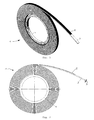
- a storage reel 1 a magnetic scale strip 2 and an intermediate layer tape 3, which are wound like a coil on a winding core 4.
- the magnetic scale strip 2 has a ferromagnetic material which is magnetized such that the magnetic scale strip 2 has magnetic domains which corresponds to a pole pitch 12 having the same pole length 6.
- the winding core 4 is a cylindrical ring formed to support the winding consisting of the magnetic scale tape 2 and the intermediate layer tape 3.
- the width of the magnetic scale strip 2, the width of the intermediate layer strip 3 and the axial extent of the winding core 4 are the same and are for example 10 mm.
- the length of the magnetic scale strip 2 is by way of example 50 m, wherein the spacer tape 3 is formed slightly longer than the magnetic scale strip 2, so that at the outer end of the magnetic scale strip 2 and the Interlayer tape 3 formed a projection of the spacer tape 3 is formed by the magnetic scale strip 2.
- the storage bobbin 1 has a diameter of exemplarily 600 mm and weighs 4.5 kg by way of example.
- the magnetic scale strip 2 is placed on the intermediate layer belt 3, so that from the magnetic scale strip 2 and the intermediate layer strip 3 quasi a winding tape is formed, wherein the intermediate layer band 3 radially inwardly and the magnetic scale strip 2 are arranged radially outboard.
- the magnetic scale strip 2 and the intermediate layer strip 3 alternate alternately from one turn to the next in the radial direction of the winding core 4.
- the intermediate layer tape 3 Only at the first innermost superimposition of the magnetic scale strip 2, the intermediate layer tape 3 is provided, so that a direct superimposition of the magnetic scale strip 2 is prevented in the storage reel 1.
- the magnetic scale strip 2 is placed on the intermediate layer belt 3 without an adhesion-promoting layer, wherein adhesion forces cause the magnetic scale strip 2 and the intermediate layer strip 3 to stick together.
- the magnetic scale tape 2 is stuck on the intermediate layer tape 3.
- the interlayer belt 3 is made of a polyethylene foam, so that the interlayer belt 3 is paramagnetic.
- the magnetic scale strip 2 has the pole pitch 12 whose pole lengths 6 are each 5 mm, the pole pitch 12 being uniform.
- accuracy requirements are to be made in terms of the stability of the pole pitch 12.
- the minimum required thickness 5 of the intermediate layer strip 3 is to be determined.
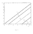
- the in FIG. 3 shown diagram.
- the pole length is plotted in millimeters over the abscissa and the interlayer tape thickness 5 in millimeters over the ordinate.
- a family of curves is shown in the diagram, with the linear course of the intermediate layer strip thickness 5 with respect to the pole length 6 being shown for selected tolerated pole length changes.
- the curve indicated by the reference numeral 7 relates to the tolerated pole length change of 0 .mu.m / m
- the line indicated by the reference numeral 8 relates to the pole length change of 10 .mu.m / m
- the line marked by the reference numeral 9 relates to the pole length change of 25 .mu.m / m
- the line marked with the reference numeral 10 relates to the pole length change of 40 ⁇ m / m
- the line indicated by the reference numeral 11 relates to the pole length change of 50 ⁇ m / m.
- the magnetic scale tape 2 is to be provided, wherein the magnetic scale tape 2 is magnetized with the pole pitch 12 having the predetermined pole length 6.
- the winding core 4 is to be provided.
- the tolerated pole length change 7 to 11 is to be defined.
- the pole length 6 of the magnetic scale strip 2 is shown in the diagram FIG. 3 to determine the minimum required intermediate layer thickness 5.
- the intermediate layer strip 3 is to be provided with its intermediate layer strip thickness, which is also greater than that according to the diagram in FIG. 3 determined thickness can be.
- the intermediate layer tape 3 may be formed of a plurality of layers, which are provided for example in standard thicknesses. For example, if an intermediate layer thickness 5 of 4 mm required, so would be for the Interlayer belt 3 two layers, each with 3 mm conceivable, so that the intermediate layer strip 3 results in the thickness of 6 mm.
- the magnetic scale strip 2 and the intermediate layer strip 3 are to be placed flat against one another, wherein the magnetic scale strip 2 and the intermediate layer strip 3 adhere to one another by adhesion forces.
- the winding tape formed thereby is to wind up on the winding core 4 in a spiral manner, wherein the intermediate layer band 3 is arranged on the inside and the magnetic scale band 2 on the outside per winding.
- the intermediate layer tape 3 is made of plastic, in particular a polyethylene foam.
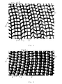
- FIGS. 4 and 5 In each case a section of a side view of the storage coil 1 is shown with magnetic contrast, wherein the bright areas indicate fields with identical magnetic polarity.
- the pole length 6 is 5 mm.
- the spacer tape 3 is shown with a thickness 5 of 3 mm, wherein the individual windings are magnetically coupled together and thereby form common magnetic domains. This results in the tolerated pole length change 9 of 25 ⁇ m / m.
- the intermediate layer strip thickness 5 is 6 mm, so that a tolerated pole length change of 0 ⁇ m / m results therefrom.
- the individual windings are magnetically decoupled from each other and can not form common magnetic domains.
Landscapes
- Physics & Mathematics (AREA)
- General Physics & Mathematics (AREA)
- Storage Of Web-Like Or Filamentary Materials (AREA)
Description
- Die Erfindung betrifft eine Aufbewahrungsspule mit einem Magnetmaßstabband und ein Verfahren zum Aufbewahren des Magnetmaßstabbands mit der Aufbewahrungsspule.
- Ein Magnetmaßstabband ist aus XP002699408 bekannt.
- Im Werkzeugmaschinenbau ist es bekannt einen magnetischen Linearmaßstab zur Bestimmung einer absoluten Position eines Werkzeugschlittens zu verwenden. Hierzu ist der magnetische Linearmaßstab in Form eines langgestreckten magnetisierten Bands auf eine Referenzschiene aufgebracht, wobei das Band wechselseitig mit Nordpolen und Südpolen magnetisiert ist. Daraus ergibt sich für den Linearmaßstab ein binäres Bitmuster, das von einem Sensor gelesen wird, der an dem Werkzeugschlitten angebracht ist. Der Linearmaßstab ist beispielsweise mit einer Inkrementalspur versehen, die eine Polteilung bei gleichen Pollängen und somit einen regelmäßigen Wechsel zwischen Südpolen und Nordpolen aufweist.
- Herkömmlich ist das Magnetmaßstabband von einem biegsamen, beispielsweise aus einem Kunststoff hergestellten Trägerband gebildet, das ferromagnetisches Material beinhaltet. Bei der Herstellung des Magnetmaßstabbands wird das ferromagnetische Material derart magnetisiert, dass das Magnetmaßstabband magnetische Domänen hat, die der Polteilung mit den Pollängen entspricht. Das Magnetmaßstabband wird beispielsweise mit einer Länge von 50 m bei einer Breite von 10 mm ausgeliefert. Um das Magnetmaßstabband auf ein gut handhabbares Packmaß zu bringen, ist es bekannt, das Magnetmaßstabband auf einen Wickelkern spiralartig aufzuwickeln, wobei eine derart gebildete Spule einen Durchmesser von 0,5 m bis 0,8 m und ein Gewicht von 4 kg bis 5 kg hat.
- Entsprechend der Verwendung des Magnetmaßstabbands sind Anforderungen hinsichtlich der Maßgenauigkeit der Polteilung des Magnetmaßstabbands gestellt. Beträgt die Polteilung zwischen 1 mm und 5 mm liegt eine mögliche Toleranz der Pollängen zwischen Ist- und Sollwerten im Bereich von einigen Mikrometern. Somit sind neben der Herstellung des Magnetmaßstabbands an die Lagerung und den Transport des Magnetmaßstabbands entsprechende Anforderungen zu stellen, dass die geforderte Genauigkeit der Polteilung erhalten bleibt.
- Aufgabe der Erfindung ist es eine Aufbewahrungsspule mit einem Magnetmaßstabband und ein Verfahren zum Aufbewahren des Magnetmaßstabbands in der Aufbewahrungsspule zu schaffen, wobei die Genauigkeit der Polteilung des Magnetmaßstabbands innerhalb einer vorgegebenen Toleranz erhalten bleibt.
- Die Aufgabe wird gelöst mit den Merkmalen der Patentansprüche 1 und 7. Bevorzugte Ausgestaltungen dazu sind in den weiteren Patentansprüchen angegeben.
- Die erfindungsgemäße Aufbewahrungsspule weist einen Wickelkern und ein ein ferromagnetisches Material aufweisendes Magnetmaßstabband, das mit einer Polteilung mit vorherbestimmten Pollängen magnetisiert ist, sowie ein Zwischenlagenband auf, das mindestens die Breite und die Länge des Magnetmaßstabbands hat und an das das Magnetmaßstabband flächig angelegt ist, wobei das Magnetmaßstabband zusammen mit dem Zwischenlagenband auf den Wickelkern in mehreren Windungen spiralenartig aufgewickelt ist, so dass in Radialrichtung des Wickelkerns Windung für Windung das Magnetmaßstabband und das Zwischenlagenband sich abwechseln, wobei das Zwischenlagenband aus einem paramagnetischen Material ist und eine Dicke hat, die gleich oder größer einer Minimaldicke ist, die derart bestimmt ist, dass die einzelnen Windungen des Magnetmaßstabbands von dem Zwischenlagenband derart voneinander magnetisch entkoppelt sind, dass im Abwickelzustand die Pollängen des Magnetmaßstabbands trotz der magnetischen Wechselwirkung der einzelnen Windungen lediglich einer Pollängenveränderung unterliegen, die unterhalb einer vorgegebenen tolerierten Pollängenveränderung liegt.
- Somit wird vorteilhaft erreicht, dass das in der Aufbewahrungsspule aufgewickelte Magnetmaßstabband aufgrund der magnetischen Wechselwirkung zwischen den einzelnen Windungen lediglich innerhalb eines noch tolerierbaren Maßes verstimmt wird. Mit dem Zwischenlagenband ist die magnetische Entkopplung der einzelnen Windungen des Magnetmaßstabbands erreicht, wodurch im Abwickelzustand die Pollängenänderung, die im Aufwickelzustand von benachbarten Windungen des Magnetmaßstabbands verursacht wurde, lediglich zu einer Pollängenveränderung führt, die innerhalb der vorgegebenen tolerierten Pollängenveränderung liegt.
- Bevorzugtermaßen ist die Minimaldicke direkt proportional zur minimalen vorherbestimmten Pollänge. Ferner ist es bevorzugt, dass die Minimaldicke direkt proportional zur um die vorgegebene tolerierte Pollängenveränderung reduzierten minimalen vorherbestimmten Pollänge ist, wobei die Minimaldicke und die minimale vorherbestimmte Pollänge in Millimeter und die vorgegebene tolerierte Pollängenveränderung in µm/m angegeben sind. Hierbei ist es bevorzugt, dass die Minimaldicke gleich dem eins bis zweifachen, insbesondere 1,2-fachen, der Differenz aus der minimalen vorherbestimmten Pollänge und einem Zehntel der vorgegebenen tolerierten Pollängenveränderung ist. Besonders bevorzugt errechnet sich also die Minimaldicke nach der Formel: Minimaldicke = 1,2 * (minimale vorbestimmte Pollänge - ein Zehntel der vorgegebene tolerierte Pollängenveränderung). Hierbei ist die minimale vorherbestimmte Pollänge in mm, die vorgegebene tolerierte Pollängenveränderung in µm/m angegeben, woraus sich die Minimaldicke in mm ergibt. Es sind die Zahlenwerte mit den ihnen zugeordneten Einheiten zu nehmen. Überraschenderweise hat sich gezeigt, dass durch das Vorsehen des Zwischenlagenbands mit der Dicke, die der Minimaldicke entspricht oder größer ist, die Polteilung des Magnetmaßstabbands, wenn es von dem Wickelkern abgewickelt ist, lediglich eine derart geringe Pollängenveränderung erfahren hat, die unterhalb der vorgegebenen tolerierten Pollängenveränderung liegt.
- Das paramagnetische Material ist bevorzugt ein Kunststoff, insbesondere ein Polyethylenschaum. Bevorzugtermaßen ist das Zwischenlagenband von mehreren Lagen gebildet, deren Gesamtdicke gleich oder größer der Minimaldicke ist. Die Lagen liegen flächig aneinander und bilden so das Zwischenlagenband, wobei durch das entsprechende Vorsehen von den mehreren Lagen mehrere Abstufungen in der Dicke des Zwischenlagenbands gebildet werden können. Dies ist insbesondere dann vorteilhaft, wenn das Zwischenlagenband lediglich mit einer Normdicke zur Verfügung steht, wobei durch das Übereinanderlegen der mehreren Lagen die Minimaldicke für das Zwischenlagenband angenähert werden kann.
- Das erfindungsgemäße Verfahren zum Aufbewahren eines ein ferromagnetisches Material aufweisenden Magnetmaßstabbands mit der Aufbewahrungsspule weist die Schritte auf: Bereitstellen des Wickelkerns und des Magnetmaßstabbands, das mit der Polteilung mit den vorherbestimmten Pollängen magnetisiert ist; Bestimmen der Minimaldicke des Zwischenlagenbands derart, dass im Aufwickelzustand des Magnetmaßstabbands die einzelnen Windungen des Magnetmaßstabbands von dem Zwischenlagenband derart voneinander magnetisch entkoppelt sind, dass im Abwickelzustand die Pollängen des Magnetmaßstabbands trotz der magnetischen Wechselwirkung der einzelnen Windungen lediglich einer Pollängenveränderung unterliegen, die unterhalb einer vorgegebenen tolerierten Pollängenveränderung liegt; Bereitstellen des Zwischenlagenbands mit einer Breite, die mindestens der Breite des Magnetmaßstabbands entspricht, einer Länge, die mindestens der Länge des Magnetmaßstabbands entspricht, und einer Dicke, die gleich oder größer der Minimaldicke ist; Zusammenbringen des Magnetmaßstabbands und des Zwischenlagenbands, so dass das Magnetmaßstabband und das Zwischenlagenband flächig aneinanderliegen; spiralartiges Aufwickeln des Magnetmaßstabbands zusammen mit dem Zwischenlagenband auf dem Wickelkern wobei das Magnetmaßstabband zusammen mit den Zwischenlagenband auf den Wickelkern in mehreren Windungen spiralartig aufgewickelt wird, so dass in Radialrichtung des Wickelkerns Windung für Windung das Magnetmaßstabband und das Zwischenlagenband sich abwechseln.
- Im Folgenden werden bevorzugte Ausführungsbeispiele der erfindungsgemäßen Aufbewahrungsspule anhand der beigefügten schematischen Zeichnungen erläutert. Es zeigen:
-
Figur 1 eine perspektivische Ansicht einer erfindungsgemäßen Aufbewahrungsspule, -
Figur 2 eine Draufsicht der erfindungsgemäßen Aufbewahrungsspule ausFigur 1 , -
Figur 3 ein Diagramm zur Ermittlung einer Minimaldicke eines Zwischenlagenbands der Aufbewahrungsspule ausFigur 1 , -
Figur 4 eine Seitenansicht mit magnetischem Kontrast einer ersten Ausführungsform der Aufbewahrungsspule ausFigur 1 und -
Figur 5 eine Seitenansicht mit magnetischem Kontrast einer zweiten Ausführungsform der Aufbewahrungsspule ausFigur 1 . - Wie es aus
Figuren 1 bis 5 ersichtlich ist, weist eine Aufbewahrungsspule 1 ein Magnetmaßstabband 2 und ein Zwischenlagenband 3 auf, die spulenartig auf einen Wickelkern 4 aufgewickelt sind. Das Magnetmaßstabband 2 weist ein ferromagnetisches Material auf, das derart magnetisiert ist, dass das Magnetmaßstabband 2 magnetische Domänen hat, die einer Polteilung 12 mit gleichen Pollängen 6 entspricht. Der Wickelkern 4 ist ein zylindrischer Ring, der zum Tragen der Wicklung bestehend aus dem Magnetmaßstabband 2 und dem Zwischenlagenband 3 ausgebildet ist. Die Breite des Magnetmaßstabbands 2, die Breite des Zwischenlagenbands 3 und die axiale Erstreckung des Wickelkerns 4 sind gleich und betragen beispielhaft 10 mm. Die Länge des Magnetmaßstabbands 2 beträgt beispielhaft 50 m, wobei das Zwischenlagenband 3 etwas länger als das Magnetmaßstabband 2 ausgebildet ist, so dass am außenliegenden Ende der von dem Magnetmaßstabband 2 und dem Zwischenlagenband 3 gebildeten Wicklung ein Überstand des Zwischenlagenbands 3 von dem Magnetmaßstabband 2 ausgebildet ist. Die Aufbewahrungsspule 1 hat einen Durchmesser von beispielhaft 600 mm und wiegt beispielhaft 4,5 kg. - Das Magnetmaßstabband 2 ist auf das Zwischenlagenband 3 gelegt, so dass von dem Magnetmaßstabband 2 und dem Zwischenlagenband 3 quasi ein Wickelband gebildet ist, wobei das Zwischenlagenband 3 radial innenliegend und das Magnetmaßstabband 2 radial außenliegend angeordnet sind. Dadurch wechseln sich von Windung zu Windung in Radialrichtung des Wickelkerns 4 gesehen das Magnetmaßstabband 2 und das Zwischenlagenband 3 wechselseitig ab. Für die radial innerste Windung des Magnetmaßstabbands 2 ist auf das Zwischenlagenband 3 verzichtet, da das Magnetmaßstabband 2 direkt auf dem Wickelkern 4 aufliegt. Erst beim ersten innersten Übereinanderliegen des Magnetmaßstabbands 2 ist das Zwischenlagenband 3 vorgesehen, so dass ein unmittelbares Aufeinanderliegen des Magnetmaßstabbands 2 in der Aufbewahrungsspule 1 unterbunden ist.
- Das Magnetmaßstabband 2 ist ohne eine Haftvermittlungsschicht auf das Zwischenlagenband 3 aufgelegt, wobei Adhäsionskräfte ein Aneinanderhaften des Magnetmaßstabbands 2 und des Zwischenlagenbands 3 bewirken. Alternativ ist das Magnetmaßstabband 2 auf das Zwischenlagenband 3 geklebt. Das Zwischenlagenband 3 ist aus einem Polyethylenschaum hergestellt, so dass das Zwischenlagenband 3 paramagnetisch ist.
- Gemäß den in
Figuren 4 und 5 gezeigten Ausführungsformen weist das Magnetmaßstabband 2 die Polteilung 12 auf, deren Pollängen 6 jeweils 5 mm betragen, wobei die Polteilung 12 gleichförmig ist. An die Aufbewahrung des Magnetmaßstabbands 2 sind Genauigkeitsanforderungen hinsichtlich der Lagebeständigkeit der Polteilung 12 zu stellen. In Abhängigkeit von dieser Genauigkeitsanforderung und der Pollänge 6 ist die mindest erforderliche Dicke 5 des Zwischenlagenbands 3 zu ermitteln. Zur Ermittlung der Zwischenlagenbanddicke 5 ist das inFigur 3 gezeigte Diagramm heranzuziehen. In dem Diagramm ist über die Abszisse die Pollänge 6 in Millimeter und über die Ordinate die Zwischenlagenbanddicke 5 in Millimeter aufgetragen. In dem Diagramm ist eine Kurvenschar gezeigt, wobei für ausgewählte tolerierte Pollängenveränderungen der lineare Verlauf der Zwischenlagenbanddicke 5 gegenüber der Pollänge 6 gezeigt ist. Die mit dem Bezugszeichen 7 gekennzeichnete Kurve betrifft die tolerierte Pollängenveränderung von 0 µm/m, die mit dem Bezugszeichen 8 gekennzeichnete Linie betrifft die Pollängenveränderung von 10 µm/m, die mit dem Bezugszeichen 9 gekennzeichnete Linie betrifft die Pollängenveränderung von 25 µm/m, die mit dem Bezugszeichen 10 gekennzeichnete Linie betrifft die Pollängenveränderung von 40 µm/m und die mit dem Bezugszeichen 11 gekennzeichnete Linie betrifft die Pollängenveränderung von 50 µm/m. - Der im Diagramm gemäß
Figur 3 gezeigte Kurvenschar 7 bis 11 liegt die Formel zugrunde: {Zwischenlagendicke 6 in [mm]} =1,2 * ({Pollänge 6 in [mm]} - {tolerierte Pollängenveränderung in [µm/m]}/10). - Zum Aufbewahren des Magnetmaßstabbands 2 mit der Aufbewahrungsspule 1 ist wie folgt vorzugehen: das Magnetmaßstabband 2 ist bereitzustellen, wobei das Magnetmaßstabband 2 mit der Polteilung 12 mit den vorherbestimmten Pollängen 6 magnetisiert ist. Zusätzlich ist der Wickelkern 4 bereitzustellen. Für das Magnetmaßstabband 2 ist die tolerierte Pollängenveränderung 7 bis 11 festzulegen. In Abhängigkeit der tolerierten Pollängenveränderung 7 bis 11 und der Pollänge 6 des Magnetmaßstabbands 2 ist gemäß dem Diagramm aus
Figur 3 die mindest erforderliche Zwischenlagenbanddicke 5 zu bestimmen. Das Zwischenlagenband 3 ist mit ihrer Zwischenlagenbanddicke bereitzustellen, die auch größer als die gemäß dem Diagramm inFigur 3 ermittelten Dicke sein kann. So kann beispielsweise das Zwischenlagenband 3 aus mehreren Lagen gebildet sein, die beispielsweise in Normdicken bereitgestellt sind. Ist beispielsweise eine Zwischenlagenbanddicke 5 von 4 mm gefordert, so wären für das Zwischenlagenband 3 zwei Lagen mit je 3 mm denkbar, so dass sich das Zwischenlagenband 3 mit der Dicke von 6 mm ergibt. - Das Magnetmaßstabband 2 und das Zwischenlagenband 3 sind flächig aneinander zu legen, wobei durch Adhäsionskräfte das Magnetmaßstabband 2 und das Zwischenlagenband 3 aneinander haften. Das dadurch gebildete Wickelband ist spiralartig auf den Wickelkern 4 aufzuwickeln, wobei pro Wicklung das Zwischenlagenband 3 innenseitig und das Magnetmaßstabband 2 außenseitig angeordnet ist. Das Zwischenlagenband 3 ist aus Kunststoff, insbesondere einem Polyethylenschaum, hergestellt.
- In
Figuren 4 und 5 ist jeweils ein Ausschnitt einer Seitenansicht der Aufbewahrungsspule 1 mit magnetischem Kontrast gezeigt, wobei die hellen Bereiche Felder mit identischer magnetischer Polarität anzeigen. In beiden Ausführungsformen beträgt die Pollänge 6 5 mm. Gemäß der inFigur 4 gezeigten Ausführungsform ist das Zwischenlagenband 3 mit einer Dicke 5 von 3 mm gezeigt, wobei die einzelnen Wicklungen magnetisch miteinander gekoppelt sind und dadurch gemeinsame magnetische Domänen bilden. Daraus ergibt sich die tolerierte Pollängenveränderung 9 von 25 µm/m. Bei der inFigur 5 gezeigten Ausführungsform beträgt die Zwischenlagenbanddicke 5 6 mm, so dass sich daraus eine tolerierte Pollängenveränderung von 0 µm/m. Bei dieser Ausführungsform sind die einzelnen Wicklungen magnetisch voneinander entkoppelt und können keine gemeinsamen magnetischen Domänen bilden. -
- 1
- Aufbewahrungsspule
- 2
- Magnetmaßstabband
- 3
- Zwischenlagenband
- 4
- Wickelkern
- 5
- Zwischenlagenbanddicke
- 6
- Pollänge
- 7
- tolerierte Pollängenveränderung: 0 µm/m
- 8
- tolerierte Pollängenveränderung: 10 µm/m
- 9
- tolerierte Pollängenveränderung: 25 µm/m
- 10
- tolerierte Pollängenveränderung: 40 µm/m
- 11
- tolerierte Pollängenveränderung: 50 µm/m
- 12
- Polteilung
Claims (12)
- Aufbewahrungsspule mit einem Wickelkern (4) und einem ein ferromagnetisches Material aufweisenden Magnetmaßstabband (2), das mit einer Polteilung (12) mit vorherbestimmten Pollängen (6) magnetisiert ist, sowie einem Zwischenlagenband (3), das mindestens die Breite und die Länge des Magnetmaßstabbands (2) hat und an das das Magnetmaßstabband (2) flächig angelegt ist, wobei das Magnetmaßstabband (2) zusammen mit dem Zwischenlagenband (3) auf den Wickelkern (4) in mehreren Windungen spiralartig aufgewickelt ist, so dass in Radialrichtung des Wickelkerns (4) Windung für Windung das Magnetmaßstabband (2) und das Zwischenlagenband (3) sich abwechseln, wobei das Zwischenlagenband (3) aus einem paramagnetischen Material ist und eine Dicke (5) hat, die gleich oder größer einer Minimaldicke ist, die derart bestimmt ist, dass die einzelnen Windungen des Magnetmaßstabbands (2) von dem Zwischenlagenband (3) derart voneinander magnetisch entkoppelt sind, dass im Abwickelzustand die Pollängen (12) des Magnetmaßstabbands (2) trotz der magnetischen Wechselwirkung der einzelnen Windungen lediglich einer Pollängenveränderung unterliegen, die unterhalb einer vorgegebenen tolerierten Pollängenveränderung (7 bis 11) liegt.
- Aufbewahrungsspule gemäß Anspruch 1, wobei die Minimaldicke direkt proportional zur minimalen vorherbestimmten Pollänge (6) ist.
- Aufbewahrungsspule gemäß Anspruch 1 oder 2, wobei die Minimaldicke direkt proportional zur um die vorgegebene tolerierte Pollängenveränderung (7 bis 11) reduzierten minimalen vorherbestimmten Pollänge (6) ist, wobei die Minimaldicke und die minimale vorherbestimmte Pollänge (6) in mm und die vorgegebene tolerierte Pollängenveränderung (7 bis 11) in µm/m angegeben sind.
- Aufbewahrungsspule gemäß Anspruch 3, wobei die Minimaldicke gleich dem eins bis zweifachen, insbesondere 1,2-fachen, der Differenz aus der minimalen vorherbestimmten Pollänge (6) und einem Zehntel der vorgegebenen tolerierten Pollängenveränderung (7 bis 11) ist.
- Aufbewahrungsspule gemäß einem der Ansprüche 1 bis 4, wobei das paramagnetische Material ein Kunststoff, insbesondere ein Polyethylenschaum, ist.
- Aufbewahrungsspule gemäß einem der Ansprüche 1 bis 5, wobei das Zwischenlagenband (3) von mehreren Lagen gebildet ist, deren Gesamtdicke gleich oder größer der Minimaldicke ist.
- Verfahren zum Aufbewahren eines ein ferromagnetisches Material aufweisenden Magnetmaßstabbands (2) mit einer Aufbewahrungsspule (1) gemäß einem der Ansprüche 1 bis 6, mit den Schritten:- Bereitstellen des Wickelkerns (4) und des Magnetmaßstabbands (2), das mit der Polteilung (12) mit den vorherbestimmten Pollängen (6) magnetisiert ist;- Bestimmen der Minimaldicke des Zwischenlagenbands (3) derart, dass im Aufwickelzustand des Magnetmaßstabbands (2) die einzelnen Windungen des Magnetmaßstabbands (2) von dem Zwischenlagenband (3) derart voneinander magnetisch entkoppelt sind, dass im Abwickelzustand die Pollängen (12) des Magnetmaßstabbands (2) trotz der magnetischen Wechselwirkung der einzelnen Windungen lediglich einer Pollängenveränderung unterliegen, die unterhalb einer vorgegebenen tolerierten Pollängenveränderung (7 bis 11) liegt;- Bereitstellen des Zwischenlagenbands (3) mit einer Breite, die mindestens der Breite des Magnetmaßstabbands (2) entspricht, einer Länge, die mindestens der Länge des Magnetmaßstabbands (2) entspricht, und einer Dicke (5), die gleich oder größer der Minimaldicke ist;- Zusammenbringen des Magnetmaßstabbands (2) und des Zwischenlagenbands (3), so dass das Magnetmaßstabband (2) und das Zwischenlagenband (3) flächig aneinanderliegen;- spiralartiges Aufwickeln des Magnetmaßstabbands (2) zusammen mit dem Zwischenlagenband (3) auf den Wickelkern (4), wobei das Magnetmaßstabband (2) zusammen mit dem Zwischenlagenband (3) auf den Wickelkern (4) in mehreren Windungen spiralartig aufgewickelt wird, so dass in Radialrichtung des Wickelkerns (4) Windung für Windung das Magnetmaßstabband (2) und das Zwischenlagerband (3) sich abwechseln.
- Verfahren gemäß Anspruch 7, wobei die Minimaldicke als direkt proportional zur minimalen vorherbestimmten Pollänge (6) bestimmt wird.
- Verfahren gemäß Anspruch 7 oder 8, wobei die Minimaldicke als direkt proportional zur um die vorgegebene tolerierte Pollängenveränderung (7 bis 11) reduzierte minimale vorherbestimmte Pollänge (6) bestimmt wird, wobei die Minimaldicke und die minimale vorherbestimmte Pollänge (6) in mm und die vorgegebene tolerierte Pollängenveränderung (7 bis 11) in µm/m angegeben werden.
- Verfahren gemäß Anspruch 9, wobei die Minimaldicke als gleich dem eins bis zweifachen, insbesondere 1,2-fachen, der Differenz aus der minimalen vorherbestimmten Pollänge (6) und einem Zehntel der vorgegebenen tolerierten Pollängenveränderung (7 bis 11) bestimmt wird.
- Verfahren gemäß einem der Ansprüche 7 bis 10, wobei das paramagnetische Material ein Kunststoff, insbesondere ein Polyethylenschaum, ist.
- Verfahren gemäß einem der Ansprüche 7 bis 11, wobei das Zwischenlagenband (3) von mehreren Lagen gebildet wird, deren Gesamtdicke (5) gleich oder größer der Minimaldicke ist.
Applications Claiming Priority (1)
| Application Number | Priority Date | Filing Date | Title |
|---|---|---|---|
| DE201210101486 DE102012101486B3 (de) | 2012-02-24 | 2012-02-24 | Aufbewahrungsspule mit einem Magnetmaßstabband und Verfahren zum Aufbewahren des Magnetmaßstabbands |
Publications (2)
| Publication Number | Publication Date |
|---|---|
| EP2631605A1 EP2631605A1 (de) | 2013-08-28 |
| EP2631605B1 true EP2631605B1 (de) | 2014-11-26 |
Family
ID=47750508
Family Applications (1)
| Application Number | Title | Priority Date | Filing Date |
|---|---|---|---|
| EP20130156584 Active EP2631605B1 (de) | 2012-02-24 | 2013-02-25 | Aufbewahrungsspule mit einem Magnetmaßstabband und Verfahren zum Aufbewahren des Magnetmaßstabbands |
Country Status (2)
| Country | Link |
|---|---|
| EP (1) | EP2631605B1 (de) |
| DE (2) | DE102012101486B3 (de) |
Family Cites Families (3)
| Publication number | Priority date | Publication date | Assignee | Title |
|---|---|---|---|---|
| GB8616240D0 (en) * | 1986-07-03 | 1986-08-13 | Renishaw Plc | Opto-electronic scale reading apparatus |
| JP2640275B2 (ja) * | 1989-07-27 | 1997-08-13 | 富士写真フイルム株式会社 | 磁気記録媒体 |
| US6427934B1 (en) * | 1998-11-12 | 2002-08-06 | Quantum Corporation | Tape reel for minimizing print through |
-
2012
- 2012-02-24 DE DE201210101486 patent/DE102012101486B3/de not_active Expired - Fee Related
-
2013
- 2013-02-25 EP EP20130156584 patent/EP2631605B1/de active Active
- 2013-02-25 DE DE201320012018 patent/DE202013012018U1/de not_active Expired - Lifetime
Also Published As
| Publication number | Publication date |
|---|---|
| DE202013012018U1 (de) | 2015-02-02 |
| DE102012101486B3 (de) | 2013-06-20 |
| EP2631605A1 (de) | 2013-08-28 |
Similar Documents
| Publication | Publication Date | Title |
|---|---|---|
| DE102008014075B4 (de) | Absolutwertcodierer | |
| EP1586135A1 (de) | Antennenkern | |
| DE2855638C2 (de) | Verfahren zum Herstellen von länglichen Wickelkörpern aus Faserverbundwerkstoff | |
| EP0499880A1 (de) | Wickelkern für Informationsträger | |
| DE3627499A1 (de) | Fluessigkeitsstandanzeiger | |
| DE3831721A1 (de) | Drehuebertrager fuer einen recorder | |
| DE102012101486B3 (de) | Aufbewahrungsspule mit einem Magnetmaßstabband und Verfahren zum Aufbewahren des Magnetmaßstabbands | |
| DE102006016169B3 (de) | Wickelmaschine zum Wickeln solenoidförmiger Spulen mit bandförmigen Leitern | |
| DE3719306C2 (de) | ||
| EP3977491B1 (de) | Induktives bauelement und verfahren zur einstellung eines induktivitätswertes für eine gruppe von induktiven bauelementen gleicher bauform | |
| DE3820433A1 (de) | Drehmomentsensor | |
| DE3312178A1 (de) | Spule | |
| DE102008033123A1 (de) | Wicklung für einen Transformator | |
| DE9307867U1 (de) | Wickelkernvorrichtung für Informationsträgerbänder | |
| DE102019132543A1 (de) | Magnetkern aus nanokristallinem laminat für ein induktives bauelement | |
| DE68910219T2 (de) | Winkelumformer. | |
| EP2704167A1 (de) | Ringkernwicklung und Messwandler mit einer solchen Ringkernwicklung | |
| DE10157591A1 (de) | Wicklung für einen Transformator oder eine Spule | |
| EP1048932A1 (de) | Magnetischer Positionssensor, seine Verwendung und seine Herstellung | |
| WO1998010449A1 (de) | Verfahren und vorrichtung zur herstellung eines induktiven bauelementes | |
| EP1747609A1 (de) | Drehübertrager für kabelverbindungen | |
| DE3882375T2 (de) | Aufbau eines stahlcords mit hoher zugfestigkeit. | |
| WO2020165030A1 (de) | Verfahren zur bestimmung des absoluten gurtbandauszugs sowie sicherheitsgurtsystem | |
| EP2596569A2 (de) | Verfahren und vorrichtung zum herstellen eines ringförmigen maschinenelements, insbesondere zum einsatz in einer elektrischen maschine | |
| EP3933347B1 (de) | Verfahren zur herstellung einer massverkörperung |
Legal Events
| Date | Code | Title | Description |
|---|---|---|---|
| REG | Reference to a national code |
Ref country code: DE Ref legal event code: R138 Ref document number: 202013012018 Country of ref document: DE Free format text: GERMAN DOCUMENT NUMBER IS 502013000207 |
|
| PUAI | Public reference made under article 153(3) epc to a published international application that has entered the european phase |
Free format text: ORIGINAL CODE: 0009012 |
|
| AK | Designated contracting states |
Kind code of ref document: A1 Designated state(s): AL AT BE BG CH CY CZ DE DK EE ES FI FR GB GR HR HU IE IS IT LI LT LU LV MC MK MT NL NO PL PT RO RS SE SI SK SM TR |
|
| AX | Request for extension of the european patent |
Extension state: BA ME |
|
| 17P | Request for examination filed |
Effective date: 20131126 |
|
| RBV | Designated contracting states (corrected) |
Designated state(s): AL AT BE BG CH CY CZ DE DK EE ES FI FR GB GR HR HU IE IS IT LI LT LU LV MC MK MT NL NO PL PT RO RS SE SI SK SM TR |
|
| GRAP | Despatch of communication of intention to grant a patent |
Free format text: ORIGINAL CODE: EPIDOSNIGR1 |
|
| INTG | Intention to grant announced |
Effective date: 20140612 |
|
| GRAS | Grant fee paid |
Free format text: ORIGINAL CODE: EPIDOSNIGR3 |
|
| GRAA | (expected) grant |
Free format text: ORIGINAL CODE: 0009210 |
|
| AK | Designated contracting states |
Kind code of ref document: B1 Designated state(s): AL AT BE BG CH CY CZ DE DK EE ES FI FR GB GR HR HU IE IS IT LI LT LU LV MC MK MT NL NO PL PT RO RS SE SI SK SM TR |
|
| REG | Reference to a national code |
Ref country code: GB Ref legal event code: FG4D Free format text: NOT ENGLISH |
|
| REG | Reference to a national code |
Ref country code: CH Ref legal event code: EP |
|
| REG | Reference to a national code |
Ref country code: AT Ref legal event code: REF Ref document number: 698456 Country of ref document: AT Kind code of ref document: T Effective date: 20141215 |
|
| REG | Reference to a national code |
Ref country code: IE Ref legal event code: FG4D Free format text: LANGUAGE OF EP DOCUMENT: GERMAN |
|
| REG | Reference to a national code |
Ref country code: DE Ref legal event code: R096 Ref document number: 502013000207 Country of ref document: DE Effective date: 20150108 |
|
| REG | Reference to a national code |
Ref country code: CH Ref legal event code: NV Representative=s name: RENTSCH PARTNER AG, CH |
|
| REG | Reference to a national code |
Ref country code: FR Ref legal event code: PLFP Year of fee payment: 3 |
|
| REG | Reference to a national code |
Ref country code: NL Ref legal event code: VDEP Effective date: 20141126 |
|
| REG | Reference to a national code |
Ref country code: LT Ref legal event code: MG4D |
|
| PG25 | Lapsed in a contracting state [announced via postgrant information from national office to epo] |
Ref country code: IS Free format text: LAPSE BECAUSE OF FAILURE TO SUBMIT A TRANSLATION OF THE DESCRIPTION OR TO PAY THE FEE WITHIN THE PRESCRIBED TIME-LIMIT Effective date: 20150326 Ref country code: LT Free format text: LAPSE BECAUSE OF FAILURE TO SUBMIT A TRANSLATION OF THE DESCRIPTION OR TO PAY THE FEE WITHIN THE PRESCRIBED TIME-LIMIT Effective date: 20141126 Ref country code: NO Free format text: LAPSE BECAUSE OF FAILURE TO SUBMIT A TRANSLATION OF THE DESCRIPTION OR TO PAY THE FEE WITHIN THE PRESCRIBED TIME-LIMIT Effective date: 20150226 Ref country code: FI Free format text: LAPSE BECAUSE OF FAILURE TO SUBMIT A TRANSLATION OF THE DESCRIPTION OR TO PAY THE FEE WITHIN THE PRESCRIBED TIME-LIMIT Effective date: 20141126 Ref country code: NL Free format text: LAPSE BECAUSE OF FAILURE TO SUBMIT A TRANSLATION OF THE DESCRIPTION OR TO PAY THE FEE WITHIN THE PRESCRIBED TIME-LIMIT Effective date: 20141126 Ref country code: PT Free format text: LAPSE BECAUSE OF FAILURE TO SUBMIT A TRANSLATION OF THE DESCRIPTION OR TO PAY THE FEE WITHIN THE PRESCRIBED TIME-LIMIT Effective date: 20150326 Ref country code: ES Free format text: LAPSE BECAUSE OF FAILURE TO SUBMIT A TRANSLATION OF THE DESCRIPTION OR TO PAY THE FEE WITHIN THE PRESCRIBED TIME-LIMIT Effective date: 20141126 |
|
| PGFP | Annual fee paid to national office [announced via postgrant information from national office to epo] |
Ref country code: LU Payment date: 20150219 Year of fee payment: 3 |
|
| PG25 | Lapsed in a contracting state [announced via postgrant information from national office to epo] |
Ref country code: SE Free format text: LAPSE BECAUSE OF FAILURE TO SUBMIT A TRANSLATION OF THE DESCRIPTION OR TO PAY THE FEE WITHIN THE PRESCRIBED TIME-LIMIT Effective date: 20141126 Ref country code: CY Free format text: LAPSE BECAUSE OF FAILURE TO SUBMIT A TRANSLATION OF THE DESCRIPTION OR TO PAY THE FEE WITHIN THE PRESCRIBED TIME-LIMIT Effective date: 20141126 Ref country code: LV Free format text: LAPSE BECAUSE OF FAILURE TO SUBMIT A TRANSLATION OF THE DESCRIPTION OR TO PAY THE FEE WITHIN THE PRESCRIBED TIME-LIMIT Effective date: 20141126 Ref country code: HR Free format text: LAPSE BECAUSE OF FAILURE TO SUBMIT A TRANSLATION OF THE DESCRIPTION OR TO PAY THE FEE WITHIN THE PRESCRIBED TIME-LIMIT Effective date: 20141126 Ref country code: RS Free format text: LAPSE BECAUSE OF FAILURE TO SUBMIT A TRANSLATION OF THE DESCRIPTION OR TO PAY THE FEE WITHIN THE PRESCRIBED TIME-LIMIT Effective date: 20141126 |
|
| PGFP | Annual fee paid to national office [announced via postgrant information from national office to epo] |
Ref country code: FR Payment date: 20150227 Year of fee payment: 3 |
|
| PGFP | Annual fee paid to national office [announced via postgrant information from national office to epo] |
Ref country code: BE Payment date: 20150218 Year of fee payment: 3 |
|
| PG25 | Lapsed in a contracting state [announced via postgrant information from national office to epo] |
Ref country code: SK Free format text: LAPSE BECAUSE OF FAILURE TO SUBMIT A TRANSLATION OF THE DESCRIPTION OR TO PAY THE FEE WITHIN THE PRESCRIBED TIME-LIMIT Effective date: 20141126 Ref country code: CZ Free format text: LAPSE BECAUSE OF FAILURE TO SUBMIT A TRANSLATION OF THE DESCRIPTION OR TO PAY THE FEE WITHIN THE PRESCRIBED TIME-LIMIT Effective date: 20141126 Ref country code: RO Free format text: LAPSE BECAUSE OF FAILURE TO SUBMIT A TRANSLATION OF THE DESCRIPTION OR TO PAY THE FEE WITHIN THE PRESCRIBED TIME-LIMIT Effective date: 20141126 Ref country code: EE Free format text: LAPSE BECAUSE OF FAILURE TO SUBMIT A TRANSLATION OF THE DESCRIPTION OR TO PAY THE FEE WITHIN THE PRESCRIBED TIME-LIMIT Effective date: 20141126 Ref country code: DK Free format text: LAPSE BECAUSE OF FAILURE TO SUBMIT A TRANSLATION OF THE DESCRIPTION OR TO PAY THE FEE WITHIN THE PRESCRIBED TIME-LIMIT Effective date: 20141126 |
|
| REG | Reference to a national code |
Ref country code: DE Ref legal event code: R097 Ref document number: 502013000207 Country of ref document: DE |
|
| PG25 | Lapsed in a contracting state [announced via postgrant information from national office to epo] |
Ref country code: PL Free format text: LAPSE BECAUSE OF FAILURE TO SUBMIT A TRANSLATION OF THE DESCRIPTION OR TO PAY THE FEE WITHIN THE PRESCRIBED TIME-LIMIT Effective date: 20141126 |
|
| PGFP | Annual fee paid to national office [announced via postgrant information from national office to epo] |
Ref country code: IE Payment date: 20150506 Year of fee payment: 3 |
|
| PLBE | No opposition filed within time limit |
Free format text: ORIGINAL CODE: 0009261 |
|
| STAA | Information on the status of an ep patent application or granted ep patent |
Free format text: STATUS: NO OPPOSITION FILED WITHIN TIME LIMIT |
|
| PG25 | Lapsed in a contracting state [announced via postgrant information from national office to epo] |
Ref country code: MC Free format text: LAPSE BECAUSE OF FAILURE TO SUBMIT A TRANSLATION OF THE DESCRIPTION OR TO PAY THE FEE WITHIN THE PRESCRIBED TIME-LIMIT Effective date: 20141126 |
|
| 26N | No opposition filed |
Effective date: 20150827 |
|
| PG25 | Lapsed in a contracting state [announced via postgrant information from national office to epo] |
Ref country code: IT Free format text: LAPSE BECAUSE OF FAILURE TO SUBMIT A TRANSLATION OF THE DESCRIPTION OR TO PAY THE FEE WITHIN THE PRESCRIBED TIME-LIMIT Effective date: 20141126 |
|
| PG25 | Lapsed in a contracting state [announced via postgrant information from national office to epo] |
Ref country code: SI Free format text: LAPSE BECAUSE OF FAILURE TO SUBMIT A TRANSLATION OF THE DESCRIPTION OR TO PAY THE FEE WITHIN THE PRESCRIBED TIME-LIMIT Effective date: 20141126 |
|
| PG25 | Lapsed in a contracting state [announced via postgrant information from national office to epo] |
Ref country code: BE Free format text: LAPSE BECAUSE OF NON-PAYMENT OF DUE FEES Effective date: 20160229 |
|
| PG25 | Lapsed in a contracting state [announced via postgrant information from national office to epo] |
Ref country code: LU Free format text: LAPSE BECAUSE OF NON-PAYMENT OF DUE FEES Effective date: 20160225 |
|
| REG | Reference to a national code |
Ref country code: CH Ref legal event code: PL |
|
| PG25 | Lapsed in a contracting state [announced via postgrant information from national office to epo] |
Ref country code: LI Free format text: LAPSE BECAUSE OF NON-PAYMENT OF DUE FEES Effective date: 20160229 Ref country code: CH Free format text: LAPSE BECAUSE OF NON-PAYMENT OF DUE FEES Effective date: 20160229 |
|
| REG | Reference to a national code |
Ref country code: FR Ref legal event code: ST Effective date: 20161028 |
|
| REG | Reference to a national code |
Ref country code: IE Ref legal event code: MM4A |
|
| PG25 | Lapsed in a contracting state [announced via postgrant information from national office to epo] |
Ref country code: MT Free format text: LAPSE BECAUSE OF FAILURE TO SUBMIT A TRANSLATION OF THE DESCRIPTION OR TO PAY THE FEE WITHIN THE PRESCRIBED TIME-LIMIT Effective date: 20141126 |
|
| PG25 | Lapsed in a contracting state [announced via postgrant information from national office to epo] |
Ref country code: IE Free format text: LAPSE BECAUSE OF NON-PAYMENT OF DUE FEES Effective date: 20160225 Ref country code: FR Free format text: LAPSE BECAUSE OF NON-PAYMENT OF DUE FEES Effective date: 20160229 |
|
| PG25 | Lapsed in a contracting state [announced via postgrant information from national office to epo] |
Ref country code: HU Free format text: LAPSE BECAUSE OF FAILURE TO SUBMIT A TRANSLATION OF THE DESCRIPTION OR TO PAY THE FEE WITHIN THE PRESCRIBED TIME-LIMIT; INVALID AB INITIO Effective date: 20130225 Ref country code: BG Free format text: LAPSE BECAUSE OF FAILURE TO SUBMIT A TRANSLATION OF THE DESCRIPTION OR TO PAY THE FEE WITHIN THE PRESCRIBED TIME-LIMIT Effective date: 20141126 |
|
| PGFP | Annual fee paid to national office [announced via postgrant information from national office to epo] |
Ref country code: GB Payment date: 20170221 Year of fee payment: 5 |
|
| PG25 | Lapsed in a contracting state [announced via postgrant information from national office to epo] |
Ref country code: GR Free format text: LAPSE BECAUSE OF FAILURE TO SUBMIT A TRANSLATION OF THE DESCRIPTION OR TO PAY THE FEE WITHIN THE PRESCRIBED TIME-LIMIT Effective date: 20141126 |
|
| PG25 | Lapsed in a contracting state [announced via postgrant information from national office to epo] |
Ref country code: TR Free format text: LAPSE BECAUSE OF FAILURE TO SUBMIT A TRANSLATION OF THE DESCRIPTION OR TO PAY THE FEE WITHIN THE PRESCRIBED TIME-LIMIT Effective date: 20141126 |
|
| PG25 | Lapsed in a contracting state [announced via postgrant information from national office to epo] |
Ref country code: SM Free format text: LAPSE BECAUSE OF FAILURE TO SUBMIT A TRANSLATION OF THE DESCRIPTION OR TO PAY THE FEE WITHIN THE PRESCRIBED TIME-LIMIT Effective date: 20141126 |
|
| PG25 | Lapsed in a contracting state [announced via postgrant information from national office to epo] |
Ref country code: MK Free format text: LAPSE BECAUSE OF FAILURE TO SUBMIT A TRANSLATION OF THE DESCRIPTION OR TO PAY THE FEE WITHIN THE PRESCRIBED TIME-LIMIT Effective date: 20141126 |
|
| GBPC | Gb: european patent ceased through non-payment of renewal fee |
Effective date: 20180225 |
|
| PG25 | Lapsed in a contracting state [announced via postgrant information from national office to epo] |
Ref country code: AL Free format text: LAPSE BECAUSE OF FAILURE TO SUBMIT A TRANSLATION OF THE DESCRIPTION OR TO PAY THE FEE WITHIN THE PRESCRIBED TIME-LIMIT Effective date: 20141126 |
|
| PG25 | Lapsed in a contracting state [announced via postgrant information from national office to epo] |
Ref country code: GB Free format text: LAPSE BECAUSE OF NON-PAYMENT OF DUE FEES Effective date: 20180225 |
|
| REG | Reference to a national code |
Ref country code: AT Ref legal event code: MM01 Ref document number: 698456 Country of ref document: AT Kind code of ref document: T Effective date: 20180225 |
|
| PG25 | Lapsed in a contracting state [announced via postgrant information from national office to epo] |
Ref country code: AT Free format text: LAPSE BECAUSE OF NON-PAYMENT OF DUE FEES Effective date: 20180225 |
|
| REG | Reference to a national code |
Ref country code: DE Ref legal event code: R081 Ref document number: 502013000207 Country of ref document: DE Owner name: BOGEN MAGNETICS GMBH, DE Free format text: FORMER OWNER: BOGEN ELECTRONIC GMBH, 14163 BERLIN, DE |
|
| P01 | Opt-out of the competence of the unified patent court (upc) registered |
Effective date: 20230517 |
|
| PGFP | Annual fee paid to national office [announced via postgrant information from national office to epo] |
Ref country code: DE Payment date: 20260325 Year of fee payment: 14 |