EP2631374A1 - Work machine peripheral monitoring device - Google Patents
Work machine peripheral monitoring device Download PDFInfo
- Publication number
- EP2631374A1 EP2631374A1 EP10858659.5A EP10858659A EP2631374A1 EP 2631374 A1 EP2631374 A1 EP 2631374A1 EP 10858659 A EP10858659 A EP 10858659A EP 2631374 A1 EP2631374 A1 EP 2631374A1
- Authority
- EP
- European Patent Office
- Prior art keywords
- image
- risk level
- obstacle
- working machine
- hazard zone
- Prior art date
- Legal status (The legal status is an assumption and is not a legal conclusion. Google has not performed a legal analysis and makes no representation as to the accuracy of the status listed.)
- Granted
Links
Images


Classifications
-
- E—FIXED CONSTRUCTIONS
- E02—HYDRAULIC ENGINEERING; FOUNDATIONS; SOIL SHIFTING
- E02F—DREDGING; SOIL-SHIFTING
- E02F9/00—Component parts of dredgers or soil-shifting machines, not restricted to one of the kinds covered by groups E02F3/00 - E02F7/00
- E02F9/24—Safety devices, e.g. for preventing overload
-
- H—ELECTRICITY
- H04—ELECTRIC COMMUNICATION TECHNIQUE
- H04N—PICTORIAL COMMUNICATION, e.g. TELEVISION
- H04N7/00—Television systems
- H04N7/18—Closed-circuit television [CCTV] systems, i.e. systems in which the video signal is not broadcast
-
- E—FIXED CONSTRUCTIONS
- E02—HYDRAULIC ENGINEERING; FOUNDATIONS; SOIL SHIFTING
- E02F—DREDGING; SOIL-SHIFTING
- E02F9/00—Component parts of dredgers or soil-shifting machines, not restricted to one of the kinds covered by groups E02F3/00 - E02F7/00
- E02F9/26—Indicating devices
- E02F9/261—Surveying the work-site to be treated
-
- E—FIXED CONSTRUCTIONS
- E02—HYDRAULIC ENGINEERING; FOUNDATIONS; SOIL SHIFTING
- E02F—DREDGING; SOIL-SHIFTING
- E02F9/00—Component parts of dredgers or soil-shifting machines, not restricted to one of the kinds covered by groups E02F3/00 - E02F7/00
- E02F9/26—Indicating devices
- E02F9/264—Sensors and their calibration for indicating the position of the work tool
-
- F—MECHANICAL ENGINEERING; LIGHTING; HEATING; WEAPONS; BLASTING
- F04—POSITIVE - DISPLACEMENT MACHINES FOR LIQUIDS; PUMPS FOR LIQUIDS OR ELASTIC FLUIDS
- F04B—POSITIVE-DISPLACEMENT MACHINES FOR LIQUIDS; PUMPS
- F04B49/00—Control, e.g. of pump delivery, or pump pressure of, or safety measures for, machines, pumps, or pumping installations, not otherwise provided for, or of interest apart from, groups F04B1/00 - F04B47/00
- F04B49/06—Control using electricity
- F04B49/065—Control using electricity and making use of computers
-
- G—PHYSICS
- G05—CONTROLLING; REGULATING
- G05B—CONTROL OR REGULATING SYSTEMS IN GENERAL; FUNCTIONAL ELEMENTS OF SUCH SYSTEMS; MONITORING OR TESTING ARRANGEMENTS FOR SUCH SYSTEMS OR ELEMENTS
- G05B9/00—Safety arrangements
- G05B9/02—Safety arrangements electric
Landscapes
- Engineering & Computer Science (AREA)
- General Engineering & Computer Science (AREA)
- Mining & Mineral Resources (AREA)
- Civil Engineering (AREA)
- Structural Engineering (AREA)
- Mechanical Engineering (AREA)
- Computer Hardware Design (AREA)
- Physics & Mathematics (AREA)
- General Physics & Mathematics (AREA)
- Automation & Control Theory (AREA)
- Multimedia (AREA)
- Signal Processing (AREA)
- Component Parts Of Construction Machinery (AREA)
- Image Processing (AREA)
- Closed-Circuit Television Systems (AREA)
Abstract
Description
- The present invention relates to a peripheral monitoring device for monitoring obstacles present around a working machine.
- Peripheral monitoring devices for working machines such as hydraulic excavators monitor the periphery of the working machine by means of a camera and/or the like to prevent the machine from coming into contact with any obstacles (persons and objects) present around the machine during work. Techniques relating to devices of this type are intended to allow an operator to easily and readily recognize the relationship in position between the working machine and the obstacles existing around it. Among these techniques is one that achieves its intended purpose by displaying three images in superimposed form on a display device. One depicts an attitude and working zone of the working machine during the work, one is obtained by converting a camera-acquired image of the working machine periphery into a bird's-eye image of the machine as viewed diagonally from above, and one depicts an obstacle appropriately detected by the camera or other means.
JP-2008-248613-A -
- Patent Document 1:
JP-2008-248613-A - The technique described in the above document is excellent in terms of the fact that the operator can easily and readily recognize the existence of obstacles and the relationship in position between the working machine and one obstacle by viewing the images displayed in superimposed form on the display device. Incidentally, if a plurality of obstacles are displayed around the working machine, a need may arise for the operator to judge with which of the obstacles the machine is most likely to come into contact. If this is the case, the operator himself or herself will have to conduct the judgment and this judging operation will necessarily intervene in normal work (excavation). If it is assumed that the working machine will be used in such a situation, therefore, the above technique admits of improvement for enhanced working efficiency of the working machine.
- An object of the present invention is to provide a peripheral monitoring device for working machines, adapted to enable an operator to instantly recognize a position of the most potentially hazardous obstacle with respect to the working machine.
- In order to attain the above object, an aspect of the present invention includes: imaging means that acquires a peripheral image of the working machine; obstacle detecting means that detects obstacles present around the working machine, by use of the acquired image; position calculating means that calculates positions of each of the detected obstacles relative to the working machine; hazard zone calculating means that calculates a hazard zone around the working machine, based upon at least one of an attitude and motion of the working machine; determining means that determines, by the calculated positions of the obstacles, whether further obstacles are present in the calculated hazard zone; risk level setting means that sets, for any obstacles determined by the determining means to be present in the hazard zone, a contact risk level based upon at least one of the type, position, and height of each obstacle that are obtained from the acquired image; image generating means that first converts the acquired image into a bird's-eye image centering upon the working machine, and then generates an image inclusive of all elements of the working machine and hazard zone on the bird's-eye image by further imaging the bird's-eye image diagonally from above an obstacle for which the highest contact risk level is set by the risk level setting means; and display means that displays the generated image.
- The present invention makes the operator instantly recognize the position of the most potentially hazardous obstacle with respect to the working machine, and thus improves working efficiency of the working machine.
-
-
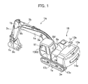
Fig. 1 is an external view of a hydraulic excavator which is an example of a working machine according to an embodiment of the present invention. -
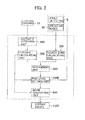
Fig. 2 is an overall configuration diagram of a peripheral monitoring device for the working machine according to the embodiment of the present invention. -
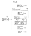
Fig. 3 is a configuration diagram of animage generating unit 600 in the embodiment of the present invention. -
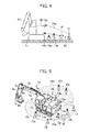
Fig. 4 is an explanatory diagram of detection zones covered when an obstacle detection unit 400 uses acamera 13a as a detector to detect obstacles and when the obstacle detection unit 400 uses a millimeter-wave radar 14a as a detector to detect obstacles. -
Fig. 5 is an explanatory diagram representing a relationship in position between the hydraulic excavator according to the embodiment of the present invention and obstacles (persons/objects) present around the hydraulic excavator. -
Fig. 6 is a flowchart of a process conducted in the obstacle detection unit 400 in the embodiment of the present invention. -
Fig. 7 is a flowchart of a process conducted in aposition calculating unit 500 in the embodiment of the present invention. -
Fig. 8 is a flowchart relating to calculating a distance between an obstacle and acamera 13 in step S520. -
Fig. 9 is a flowchart of a process conducted in a hazardzone calculating unit 700 in the embodiment of the present invention. -
Fig. 10 is a diagram illustrating an example of a hazard zone calculated when anupper structure 1d swings rightward. -
Fig. 11 is a diagram illustrating an example of a hazard zone calculated when theupper structure 1d swings leftward. -
Fig. 12 is a diagram illustrating an example of a hazard zone calculated when alower structure 1e moves in reverse. -
Fig. 13 is a flowchart of a process conducted in a determiningunit 800 in the embodiment of the present invention. -
Fig. 14 is a flowchart of a process conducted in a risklevel setting unit 2000 in the embodiment of the present invention. -
Fig. 15 is a first explanatory diagram relating to the risk level setting process conducted in the risklevel setting unit 2000. -
Fig. 16 is a second explanatory diagram relating to the risk level setting process conducted in the risklevel setting unit 2000. -
Fig. 17 is a third explanatory diagram relating to the risk level setting process conducted in the risklevel setting unit 2000. -
Fig. 18 is a flowchart of a process conducted in a bird's-eye image generator 610 in theimage generating unit 600. -
Fig. 19 is a flowchart of a process conducted in a bird's-eye visual-point setting unit 2100 (a bird's-eye position setter 2130 and bird's-eye height setter 2140) of theimage generating unit 600. -
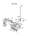
Fig. 20 is a conceptual diagram showing an example in which the bird's-eye visual-point setting unit 2100 sets a bird's-eye visual point. -
Fig. 21 is a diagram showing a first example of a monitoring image which amonitoring image generator 620 in theimage generating unit 600 generates. -
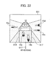
Fig. 22 is a diagram showing a second example of a monitoring image which themonitoring image generator 620 in theimage generating unit 600 generates. -
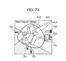
Fig. 23 is a diagram showing a third example of a monitoring image which themonitoring image generator 620 in theimage generating unit 600 generates. -
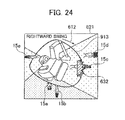
Fig. 24 is a diagram showing a fourth example of a monitoring image which themonitoring image generator 620 in theimage generating unit 600 generates. -
Fig. 25 is a diagram showing a fifth example of a monitoring image which themonitoring image generator 620 in theimage generating unit 600 generates. -
Fig. 26 is a diagram showing a sixth example of a monitoring image which themonitoring image generator 620 in theimage generating unit 600 generates. -
Fig. 27 is a diagram showing an example of a display screen of adisplay device 1300 in the embodiment of the present invention. - An embodiment of the present invention is described below using the accompanying drawings.
Fig. 1 is an external view of a hydraulic excavator which is an example of a working machine according to the embodiment of the present invention. The hydraulic excavator shown in the figure has an articulated type of front workingimplement 1A including aboom 1a, anarm 1b, and abucket 1c, each constructed to pivot in a perpendicular direction, avehicle body 1B including anupper structure 1d and alower structure 1e, and adisplay device 1300 installed inside acabin 1f. - The
cabin 1f is equipped as part of theupper structure 1d. Theboom 1a of the front workingimplement 1A has a proximal end supported from a front section of theupper structure 1d. Theboom 1a, thearm 1b, thebucket 1c, theupper structure 1d, and thelower structure 1e are driven by respective actuators, namely aboom cylinder 3a, anarm cylinder 3b, abucket cylinder 3c, a swinging motor (not shown), and leftward and rightward travelingmotors 3e and 3f (not shown). Theboom 1a, thearm 1b, thebucket 1c, and theupper structure 1d are each equipped with anangle detector - On the
upper structure 1d, arearview camera 13a, a right-sideview camera 13b, and a left-sideview camera 13c are placed as imaging means to acquire images of a peripheral region of the hydraulic excavator. Therearview camera 13a, for imaging a rear region of theupper structure 1d, is installed at the rear thereof. The right-sideview camera 13b, for imaging a right-side region of theupper structure 1d, is installed on the right side thereof. The left-sideview camera 13c, for imaging a left-side region of theupper structure 1d, is installed on the left side thereof. -
Fig. 2 is an overall configuration diagram of a peripheral monitoring device for the working machine according to the embodiment of the present invention. The same elements as in the preceding figure are each assigned the same reference number, and description of these elements is omitted herein (the same also applies to figures that follow). The peripheral monitoring device shown inFig. 2 includes thecameras position calculating unit 500, a hazardzone calculating unit 700, a determiningunit 800, a risklevel setting unit 2000, animage generating unit 600, and thedisplay device 1300. The peripheral monitoring device also includes such a processing unit (not shown) as a CPU for executing processes that each of the units conducts, and such a storage device (not shown) as a memory into which the kinds and details of processes conducted by each unit, and results of the processes are stored. - The obstacle detection unit 400 detects obstacles present around the hydraulic excavator, by using the images that the
cameras position calculating unit 500 calculates relative positions of any obstacles detected by the obstacle detection unit 400, with respect to the hydraulic excavator. - The hazard
zone calculating unit 700 calculates a hazard zone covering the hydraulic excavator periphery, based upon at least one of an attitude and motion of the hydraulic excavator. The attitude of the hydraulic excavator here (i.e., data including a swing angle of theupper structure 1d and an attitude of the front working implement 1A) is calculated from the detection angles (θ1, θ2, θ3, θ4) that theangle detectors cabin 1f, to theboom cylinder 3a, thearm cylinder 3b, thebucket cylinder 3c, the swinging motor (not shown), and/or the leftward and rightward travelingmotors 3e and 3f. Data on the operation of the hydraulic excavator is also calculated from time-varying changes in the angles (θ1, θ2, θ3, θ4) detected by theangle detectors - The determining
unit 800 determines, from the obstacle position that theposition calculating unit 500 has calculated, whether obstacles exist in the hazard zone that the hazardzone calculating unit 700 has calculated. "In the hazard zone" here refers to both an inner region of a hazard zone (i.e., the hydraulic excavator side) and a region on the hazard zone. All other regions of the hazard zone are referred to collectively as the outside of the hazard zone. - The risk
level setting unit 2000 sets, for any obstacles determined by the determiningunit 800 to be present within the hazard zone, a contact risk level based upon at least one of the type (person/object), position, and height of each obstacle that have been obtained from the images acquired by thecameras - The
image generating unit 600 first converts the images acquired by thecameras level setting unit 2000. The monitoring image generated by theimage generating unit 600 includes all elements of both of the hydraulic excavator and the hazard zone calculated by the hazardzone calculating unit 700, on the bird's-eye image. -
Fig. 3 is a configuration diagram of theimage generating unit 600 in the embodiment of the present invention. As shown in the figure, theimage generating unit 600 includes a bird's-eye image generator 610, a bird's-eye visual-point setting unit 2100, and amonitoring image generator 620. - The bird's-
eye image generator 610 converts the images acquired by thecameras eye image generator 610 generates the bird's-eye image by converting and combining the images acquired by the three cameras, namely 13a, 13b, 13c. The conversion of the camera-acquired images into the bird's-eye image can use, for example, a method described later herein or the method described inJP-2006-48451-A - The bird's-eye visual-
point setting unit 2100 sets a visual point (bird's-eye visual point) for looking down upon the bird's-eye image that the bird's-eye image generator 610 has generated, through a virtual camera (not shown). Thesetting unit 2100 includes a bird's-eye position setter 2130 and a bird's-eye height setter 2140. The bird's-eye position setter 2130 sets a position of the bird's-eye visual point, on a horizontal surface. In the present embodiment, a position of the obstacle, on the horizontal surface, that has the highest contact risk level set by the risklevel setting unit 2000, is set as the position of the bird's-eye visual point. The bird's-eye height setter 2140 sets a height (vertical) position of the bird's-eye visual point, and in the present embodiment, bird's-eye height is set so that at least the hydraulic excavator and the hazard zone calculated by the hazardzone calculating unit 700 are included in an image that the virtual camera acquires. Instead of or in combination with controlling bird's-eye height (height of the virtual camera) in this manner, the virtual camera may have its focal length (angle of view) controlled for both of the hydraulic excavator and the hazard zone to be included in the virtual camera image. - The
monitoring image generator 620 generates a monitoring image by further imaging, with the virtual camera from the bird's-eye visual point set by the bird's-eye visual-point setting unit 2100, the bird's-eye image generated by the bird's-eye image generator 610. Themonitoring image generator 620 also conducts the process of combining and displaying necessary images upon the generated monitoring image as appropriate. For example, the monitoring image preferably is such that a dummy working-machine figure graphically representing the hydraulic excavator centrally in the bird's-eye image will be displayed to enable the operator to readily understand the position of an obstacle relative to the hydraulic excavator. The dummy working-machine figure will be displayed by, for example, displaying an illustration or three-dimensional model of the hydraulic excavator centrally in the bird's-eye image. During this display, an actual attitude and motion of the hydraulic excavator will be preferably incorporated into the dummy working-machine figure to allow the operator to even more readily grasp a particular situation. - In addition, for improved operator's visibility, if the obstacle having the highest contact risk level is a person, a pictorial warning will be preferably displayed in superimposed form on the obstacle. The pictorial warning will be preferably a figure such as a star-shaped figure, or a character string such as "DANGER", and more preferably, this warning display will be provided with conspicuous coloring in the monitoring image. Conversion into the bird's-eye image will lead to the image being scaled up or down as appropriate, making the type of obstacle most likely to be difficult to identify. For this reason, if the obstacle having the highest contact risk level is a person, an image representing a person may be displayed in superimposed form on the obstacle to improve the operator's visibility. The graphic representing a person in this case will be, for example, an illustration or photograph of a person. More preferably, this illustration or photograph will be provided with conspicuous coloring in the monitoring image.
- Referring back to
Fig. 2 , thedisplay device 1300 displays the image generated by theimage generating unit 600, and as shown inFig. 1 , thedisplay device 1300 is installed inside thecabin 1f. Thedisplay device 1300 is preferably installed at a position convenient for the operator to readily confirm in visual form in thecabin 1f of the hydraulic excavator. - The peripheral monitoring device may include either a display device in addition to a computer capable of processing images, or a display device in addition to a dedicated computer for image processing.
- For improved obstacle detection performance of the obstacle detection unit 400, the
cameras upper structure 1d instead of millimeter-wave radars or other distance sensors being mounted thereupon. For example, as shown inFig. 1 , a millimeter-wave radar 14a for measuring a distance from the rear of theupper structure 1d to an obstacle is mounted below therearview camera 13a, a millimeter-wave radar 14b for measuring a distance from the right side of theupper structure 1d to another obstacle is mounted below the right-sideview camera 13b, and a millimeter-wave radar 14c for measuring a distance from the left side of theupper structure 1d to yet another obstacle is mounted below the left-sideview camera 13c. The detection performance obtained when the millimeter-wave radars 14 are used to detect obstacles is compared with that obtained when thecameras 13 are used to detect obstacles. -
Fig. 4 is an explanatory diagram of detection zones covered when the obstacle detection unit 400 uses thecamera 13a as a detector to detect obstacles and when the obstacle detection unit 400 uses the millimeter-wave radar 14a as a detector to detect obstacles. The millimeter-wave radar 14a has an ability to perform ahorizontal scan 21, whereas vertical scanning with theradar 14a is difficult. In this case, since alower structure 1e of a general hydraulic excavator is at least 1.0 m high above a ground level, the millimeter-wave radar 14a is inevitably mounted at a position of more than 1.0 m high. Accordingly if an obstacle (e.g., a sittingperson 15a whose head is about 0.8 m high) is present below or directly under the millimeter-wave radar 14a, the obstacle is outside a line of vision of the millimeter-wave radar 14a and cannot be detected. However, if thecamera 13a is installed atop thevehicle body 1B at such an angle of depression that the camera can image an object present below or directly under it, this allows imaging in both horizontal and vertical directions, resulting in even the sittingperson 15a becoming imageable and in no such a blind area occurring that the millimeter-wave radar 14a does generate. Using thecameras wave radars cameras - The following describes a case in which the peripheral monitoring device of the hydraulic excavator that has the above configuration is operated under an environment shown in
Fig. 5. Fig. 5 is an explanatory diagram representing a relationship in position between the hydraulic excavator according to the embodiment of the present invention and obstacles (persons/objects) present around the hydraulic excavator. In this figure, thecamera 13a and the millimeter-wave radar 14a are mounted at the rear of theupper structure 1d, thecamera 13b and the millimeter-wave radar 14b, at the right side, and thecamera 13c and the millimeter-wave radar 14c, at the left side. In addition, persons and objects are present in directions that are low in visibility from the operator, that is,persons sandbag 16, a road cone/pylon 17, and arubber pole 19 are present at the rear of theupper structure 1d,persons person 15e is present at the left side. -
Fig. 6 is a flowchart of the process conducted in the obstacle detection unit 400 in the embodiment of the present invention. Upon a start of peripheral monitoring by the peripheral monitoring device, the obstacle detection unit 400 first incorporates an image that is input from a camera 13 (step S401). Next, the obstacle detection unit 400 receives, as a background image from thecamera 13, for example, an input image of an immediately preceding frame or nth frame or an image separately acquired without an obstacle around (step S402). After that, the obstacle detection unit 400 uses the input image in step S401 and the background image in step S402 to create a pixel-based differential image (step S403). The obstacle detection unit 400 next binarizes the created differential image into sections of 0s, which are lower than predetermined threshold levels of about 7 to 15 in brightness, and sections of 1s, which are equal to or greater than the threshold levels in brightness, and extracts a change region relating to the positions of obstacles (step S404). - Next, whether a section that is equal to or greater than a predetermined threshold level in area is present in the change region that was extracted in step S404 is determined (step S405). In consideration of the fact that obstacles more distant from the
camera 13 will look smaller in the image, the threshold level used in step S405 is preferably set to decrease with an increase in distance from thecamera 13. If the section equal to or greater than the predetermined threshold level in area is determined in step S405 to exist in the change region, this means that an obstacle region has been determined to exist (step S406), in which case, the process proceeds to step S408. If the change region is determined to contain only sections that are lower than the predetermined threshold level, this means that no obstacles have been determined to exist (step S407), in which case, step S401 onward is repeated. - It is checked in step S408 whether other obstacle regions also exist. If the number of obstacle regions is determined in step S408 to be one, "n=1" is set (step S409). Next, "k" is set to be 1 (step S411) and after coordinates of an upper left corner and lower right corner of a rectangle circumscribed about the obstacle region have been stored into the storage device (step S413), step S401 onward is repeated.
- Conversely if a plurality of obstacle regions are determined in step S408 to exist, the number of obstacle regions is determined to be "n" (step S410). Next, "k" is set to be 1 (step S412) and after coordinates of an upper left corner and lower right corner of a rectangle circumscribed about the first of the newly detected obstacle regions have been stored into the storage device (step S413), it is checked whether coordinates have been stored for each of the remaining obstacle regions, that is, whether "k" has reached "n" (step S414). If, in step S414, "k" is found not to be up to "n", "k" is incremented by 1 (step S415), then the process is returned to step S413, and steps S413, S414, S415 are further repeated for each of any obstacle regions remaining unprocessed. The obstacles existing around the hydraulic excavator can thus be detected.
-
Fig. 7 is a flowchart of the process conducted in theposition calculating unit 500 in the embodiment of the present invention. Upon the start of peripheral monitoring by the peripheral monitoring device, theposition calculating unit 500 checks whether a circumscribed rectangle is present in the region that the obstacle detection unit 400 has extracted, that is, whether the circumscribed rectangle has its coordinates stored into the storage device by the obstacle detection unit 400 (step S501). - If the circumscribed rectangle is present in the extracted region in step S501, the process advances to step S502. If the circumscribed rectangle is not present in step S501, checking will be continued until the circumscribed rectangle exists. If the circumscribed rectangle is present in the extracted region, the circumscribed rectangle has coordinates (pixel) of a midpoint of its lower side defined as a base point for position calculation of an obstacle (step S502). In accordance with this definition, a distance from the
camera 13 to the obstacle is calculated (step +S520). -
Fig. 8 is a flowchart relating to calculating the distance between the obstacle and thecamera 13 in step S520. - The following describes the way the distance from the camera (image sensor) is calculated. The pinhole camera model, based upon the principles of this distance calculation, is the most common method used as a model for conducting conversions between an
actual ground 3D coordinate system and a coordinate system for camera image-processing screens or other camera screens. This method allowscamera 3D coordinates to be calculated by conducting a moving process and a rotational transformation uponground 3D coordinates, and 2D coordinates of the camera image to be further calculated by conducting a projection transformation upon thecalculated camera 3D coordinates. In other words, thecamera 3D coordinate system can be obtained by multiplying a combination of theground 3D coordinates and a position parameter of the camera by a rotation matrix relating to a yaw angle parameter, a depression angle parameter, and rotational angle parameter. Additionally, conducting a projective transformation with thecamera 3D coordinate system and a scale parameter yields acamera screen 2D coordinate system. The camera parameters used here are (1) the camera position parameter (theground 3D coordinates of the camera lens center, that is, visual point), (2) the depression angle parameter, (3) the yaw angle parameter, (4) the rotational angle parameter, and (5) the scale parameter. Of the five parameters, (1) the camera position parameter, (2) the depression angle parameter, and (3) the yaw angle parameter can be calculated from installation specifications data relating to the camera.
The fourth parameter, namely the rotational angle parameter, can be calculated inside the transformation since this parameter is subordinate to (2) the depression angle parameter and (3) the yaw angle parameter. The fifth parameter, namely the scale parameter, is subordinate to a zoom ratio. Each camera parameter can therefore be calculated by conducting calibration with an object of a known size after the installation of the camera, and the distance in the camera image can be calculated using the calculated parameters. - Based upon the above principles, transformation from a
ground 3D coordinate system into acamera screen 2D coordinate system takes place in step S520 to calculate the distance from thecamera 13 to the obstacle. Theposition calculating unit 500 first calculates acamera 3D coordinate transformation matrix from theground 3D coordinates by conducting a moving process and a rotational transformation (step S521), and then calculates thecamera screen 2D coordinate transformation matrix from thecamera 3D coordinates by conducting a projection transformation (step S522). Next, theposition calculating unit 500 creates an image ofcamera screen 2D coordinates using the transformation matrix which was created in step S522, and calculates the distance in the pixels of the 2D image by the calibration that uses internal parameters of the camera (step S524). After the calculation, theposition calculating unit 500 calculates the distance from the base point (midpoint of the lower side of the obstacle region) set in step S502, to thecamera 13, and advances the process to step S503. - Referring back to
Fig. 6 , it is checked in step S503 whether the circumscribed rectangle is positioned in a region close to thecamera 13, that is, whether the distance that was calculated in step S520 is equal to or less than a predetermined threshold value. If the distance calculated in step S520 is equal to or less than the predetermined threshold value, the circumscribed rectangle is determined to be positioned in the region close to thecamera 13. In this case, the extracted region is estimated to be part of the obstacle region and features of the obstacle are extracted (step S504). More specifically, it is checked in step S506 whether a circle, a feature of a helmet, is present in the extracted region. If, in step S506, the circle is determined to be present, the extracted region is determined to be a worker (person) who is wearing a helmet (step S510). If the circle is determined to be absent, the extracted region is determined to be an object (step S511). - Conversely if, in step S503, the distance calculated in step S520 is greater than the predetermined threshold value, the extracted region is estimated to be where the obstacle region is imaged in its entirety, and features of the obstacle are extracted (step S505). More specifically, it is determined in step S507 whether the extracted region has an aspect ratio close to that of a standing person or whether, when the extracted region is divided into three sections equivalent to a human head, trunk, and lower limbs, and respective profile shapes, colors, and other elements are extracted, the sections of the extracted region have a feature of the head, trunk, or lower limbs. In other words, it is checked whether height of the extracted region is greater than its width in terms of aspect ratio or whether the head of the extracted region has a fan-shaped profile, a shoulder part of the trunk has a slant profile or the trunk itself has a vertical profile, and/or the lower limbs have an inverse V-profile or a vertical profile. If in step S507 at least one of these features is found to exist in the extracted region, this region is determined to be a person (step S508). If one or none of the features is found to exist, the extracted region is determined to be an object (step S509). After the identification of the type (person/object) of extracted region in steps S508 to S511, it is further checked in step S512 whether distance calculations and type determinations have also been conducted upon all other extracted regions. If the calculations and/or the determinations are not completed, the
position calculating unit 500 returns to step S501 and repeats step S501 onward. The relative position of the obstacle detected by the obstacle detection unit 400, with respect to the hydraulic excavator, is calculated by the execution of the above process. Depending upon the determination result in step S503, a method different from the above may be applied in the following type-determination step (S506, S507). -
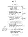
Fig. 9 is a flowchart of the process conducted in the hazardzone calculating unit 700 in the embodiment of the present invention. Upon the start of peripheral monitoring by the peripheral monitoring device, the hazardzone calculating unit 700 first takes in the output θ1 signal from theangle detector 8a detecting the pivoting angle of theboom 1a, takes in the output θ2 signal from theangle detector 8b detecting the pivoting angle of thearm 1b, takes in the output θ3 signal from theangle detector 8c detecting the pivoting angle of thebucket 1c, and takes in the output θ4 signal from theangle detector 8d detecting the pivoting angle of theupper structure 1d (step S701). Next, the hazardzone calculating unit 700 calculates coordinates and height of a distal end of thebucket 1c from the output signals θ1, θ2, θ3, θ4 (step S702), and then calculates the attitude of the hydraulic excavator by calculating a size (length) of the front working implement 1A and a direction in which theupper structure 1d swings from thelower structure 1e (step S703). - Next, the hazard
zone calculating unit 700 acquires the operation signal that is output from the operation device 30 (S704), and calculates the motion of the hydraulic excavator (moving directions of theboom 1a, thearm 1b, and thebucket 1c, swinging direction of theupper structure 1d, moving direction of thelower structure 1e, and the like), based upon the acquired operation signal (step S705). - Next, in step S707, the hazard
zone calculating unit 700 next acquires the size of the hydraulic excavator (size of theupper structure 1d and the like), stored within an excavatorspecifications storage unit 706. In step S708, theunit 700 calculates the hazard zone around the hydraulic excavator, based upon the attitude of the hydraulic excavator that was calculated in step S703, the motion of the hydraulic excavator that was calculated in step S705, and the size of the hydraulic excavator that was calculated in step S707. After the calculation of the hazard zone, the hazardzone calculating unit 700 returns to step S701 and repeats step S701 onward. - The hazard zone around the hydraulic excavator is calculated by the execution of the above process. Successive steps S701 to S708 are executed on the basis of the data constantly changing during the operation of the hydraulic excavator. Accordingly, the hazard zone is calculated in operative association with the attitude and motion of the hydraulic excavator, so that a zone to be monitored is optimized. In addition, a warning can be displayed only when truly necessary, since as described later herein, the risk
level setting unit 2000 is changing the contact risk level, depending upon whether the obstacle is present in the hazard zone or outside it. For example, if the warning is made to be displayed only when the obstacle is present in the hazard zone, a scene in which the motion of the hydraulic excavator will be limited is suppressed and working efficiency consequently improves. In the above, in terms of improving a state of the hydraulic excavator and the operative association of the hazard zone therewith, the hazard zone has been calculated on the basis of both of the attitude and motion of the hydraulic excavator. The calculation of the hazard zone, however, may be based upon either one of the attitude and motion of the hydraulic excavator. In addition to the above, the hazard zone may be calculated considering the time-varying changes in the angles θ detected by theangle detectors 8, that is, with a moving speed. -
Figs. 10 to 12 show examples of a hazard zone calculated by the hazardzone calculating unit 700. In these examples, a description is conveniently given below using animage 911 formed when the bird's-eye image (detailed later) that is obtained by converting the images that have been acquired by therearview camera 13a, the right-sideview camera 13b, and the left-sideview camera 13c, is further viewed from directly above the hydraulic excavator. -
Fig. 10 is a diagram illustrating an example of a hazard zone calculated when theupper structure 1d swings rightward. Supposing that theupper structure 1d of the hydraulic excavator swings rightward as denoted byreference number 912, the front working implement 1A also moves in a rightward direction in synchronization with the rightward swing. The hazardzone calculating unit 700 then calculates the hazard zone around the hydraulic excavator, based upon the particular motional state of the excavator. To be more specific, thehazard zone 913 wide in the rightward direction that theupper structure 1d swings, and narrow in the rearward and leftward directions that are different from the swinging direction, is calculated synchronously with the motion of the hydraulic excavator. Since thehazard zone 913 is thus calculated synchronously with the motion of the hydraulic excavator, the zone that the peripheral monitoring device is to monitor is optimized. -
Fig. 11 is a diagram illustrating an example of a hazard zone calculated when theupper structure 1d swings leftward. When theupper structure 1d swings leftward as denoted byreference number 915, theupper structure 1d also moves in the leftward direction in synchronization with the leftward swing. The hazardzone calculating unit 700 then calculates the hazard zone around the hydraulic excavator, based upon the particular motional state of the excavator. To be more specific, thehazard zone 916 wide in the leftward direction that theupper structure 1d swings, and narrow in the rearward and rightward directions that are different from the swinging direction, is calculated synchronously with the motion of the hydraulic excavator. -
Fig. 12 is a diagram illustrating an example of a hazard zone calculated when thelower structure 1e moves in reverse. When thelower structure 1e moves in reverse as denoted byreference number 917, theupper structure 1d also moves in reverse in synchronization with the reverse movement of the lower structure. The hazardzone calculating unit 700 then uses the horizontal size (width) of the hydraulic excavator, acquired in step S707, to calculate the hazard zone around the hydraulic excavator, based upon the particular motional state of the excavator. To be more specific, the hazardzone calculating unit 700 calculates thehazard zone 918 having the same width as that of the hydraulic excavator, at the rear side thereof that is the direction in which the lower structure moves. -
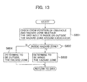
Fig. 13 is a flowchart of a process conducted in the determiningunit 800 in the embodiment of the present invention. Upon the start of peripheral monitoring by the peripheral monitoring device, the determiningunit 800 determines whether the obstacle that the obstacle detection unit 400 detected is present in the hazard zone that the hazardzone calculating unit 700 has calculated (steps S801, S802). The determination is based upon the position of the obstacle, calculated by theposition calculating unit 500. If, in step S802, the obstacle is determined to exist in the hazard zone, this result is stored into the storage device (step S803). If the obstacle is determined to exist outside the hazard zone, this result is likewise stored into the storage device (step S804). The thus-stored determination result is next used in other processing conducted by the risklevel setting unit 2000, for example. Upon completion of storage into the storage device, the determination in step S801 is repeated at fixed time intervals for all obstacles. The execution of this process sequence enables determination for obstacles in the hazard zone. -
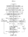
Fig. 14 is a flowchart of the process conducted in the risklevel setting unit 2000 in the embodiment of the present invention. Upon the start of peripheral monitoring by the peripheral monitoring device, the risklevel setting unit 2000 checks for obstacles in the hazard zone (step S2051), the check being based upon the determination result by the determiningunit 800. If, in step S2051, no obstacles are determined to exist in the hazard zone, the risklevel setting unit 2000 completes the process without setting a contact risk level, in other words, just by setting risk level 0 (step S2071). Conversely if, in step S2051, obstacles are determined to exist in the hazard zone, the risklevel setting unit 2000 sets an individual contact risk level for each obstacle within the hazard zone, based upon the type, position, and height of the obstacle that are obtained from the camera image. - In step S2052, if the obstacles present in the hazard zone include one for which the contact risk level is not set, the risk
level setting unit 2000 checks whether the particular obstacle is a person or an object. If the obstacle is determined in step S2052 not to be a person, that is, determined to be an object, the risklevel setting unit 2000 sets predetermined height (say, 200 cm) as the height of the obstacle (step S2073), and proceeds to step S2063. - Conversely if the obstacle is determined in step S2052 to be a person, the risk
level setting unit 2000 determines whether the circumscribed rectangle, memory-stored by the obstacle detection unit 400, has a vertically long shape or whether two adjoining sides of the rectangle are of equal length (step S2053). This determination is based upon the coordinates of the upper left corner and lower right corner of the circumscribed rectangle. If, in step S2053, the circumscribed rectangle is determined to be vertically long in shape or to have two adjoining sides of equal length, the risklevel setting unit 2000 estimates that the extracted region includes a standing person, sets predetermined height (say, 180 cm) as the height of that obstacle (step S2054), and proceeds to step S2056. In contrast, if, in step S2053, the circumscribed rectangle is determined not to be vertically long or have two adjoining sides of equal length, the risklevel setting unit 2000 estimates that the extracted region includes, for example, a person who is keeping low, sets predetermined height (say, 80 cm) as the height of that obstacle (step S2055), and proceeds to step S2056. - In step S2056, whether the motion of the hydraulic excavator is a swing (leftward swing or a rightward swing) or reversing, is determined on the basis of the operation signal from the operation device, the time-varying changes in the detection angle θ4 by the
angle detector 8d, or other information. If in step S2056 the hydraulic excavator is determined not to start swinging or reversing, the contact risk level is set to 2 (step S2057) and the process advances to step S2070. If in step S2056 the hydraulic excavator is determined to start swinging or reversing, the process advances to step S2058. - In step S2058, it is determined whether the obstacle, when compared with other obstacles in the hazard zone, is a person present at the nearest position of all obstacles existing in the direction that the hydraulic excavator is going to operate. More specifically, if in step S2058 the hydraulic excavator is determined to start swinging, a radius of a circle with a center at a swinging center of the hydraulic excavator is progressively increased from 0, until the distal end of the bucket has been reached. This draws a plurality of concentric circles. After this, it is determined whether the obstacle for which the contact risk level is to be set is a person present at the position closest to the front working implement 1A, in the swinging direction on the concentric circles. If in step S2058 the hydraulic excavator is determined to start reversing, it is determined whether the obstacle for which the contact risk level is to be set is a person present at the nearest position, at the rear of the hydraulic excavator. If in step S2058 the obstacle is determined to be a person present at the nearest position in the direction that the hydraulic excavator is going to operate, the contact risk level is set to 5 (step S2059) and the process advances to step S2070. That is to say, in step S2059, the highest contact risk level is set for, of all obstacles within the hazard zone that are determined to be persons in type, only the person (obstacle) present at the position closest to the front working implement 1A or the hydraulic excavator, in the swinging direction of the front working implement 1A or the reversing direction of the hydraulic excavator, respectively. The process advances to step S2060 if in step S2058 the obstacle is determined not to be the person present at the nearest position in the direction that the hydraulic excavator is going to operate.
- In step S2060, it is determined whether the height of the distal end of the
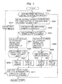
bucket 1c is the same as or less than the height of the obstacle, set in step S2054, S2055. If the height of thebucket 1c is the same as or less than the height set in step S2054, S2055, the contact risk level is set to 4 (step S2062) and the process advances to step S2070. Conversely if in step S2060 the height of thebucket 1c is determined to be greater than the height set in step S2054, S2055, the contact risk level is set to 3 (step S2061) and the process advances to step S2070. - In step S2063, whether the motion of the hydraulic excavator is a swing (leftward swing or a rightward swing) or reversing, is determined on the basis of the operation signal from the operation device, the time-varying changes in the detection angle θ4 by the
angle detector 8d, or other information. If in step S2063 the hydraulic excavator is determined not to start swinging or reversing, the contact risk level is set to 1 (step S2064) and the process advances to step S2070. Conversely if in step S2063 the hydraulic excavator is determined to start swinging or reversing, the process advances to step S2065. - In step S2065, it is determined whether the obstacle, when compared with other obstacles in the hazard zone, is an object present at the nearest position of all obstacles existing in the direction that the hydraulic excavator is going to operate. A more specific method of the determination is the same as that described in step S2058. If in step S2065 the obstacle is determined to be an object present at the nearest position in the direction that the hydraulic excavator is going to operate, the contact risk level is set to 4 (step S2066) and the process advances to step S2070. That is to say, in step S2066, the highest contact risk level is set for, of all obstacles within the hazard zone that are determined to be objects in type, only the object (obstacle) present at the position closest to the front working implement 1A or the hydraulic excavator, in the swinging direction of the front working implement 1A or the reversing direction of the hydraulic excavator, respectively. The process advances to step S2067 if in step S2065 the obstacle is determined not to be the object present at the nearest position in the direction that the hydraulic excavator is going to operate.
- In step S2067, it is determined whether the height of the distal end of the
bucket 1c is the same as or less than the height of the obstacle, set in step S2073. If the height of thebucket 1c is the same as or less than the height set in step S2073, the contact risk level is set to 3 (step S2069) and the process advances to step S2070. Conversely if in step S2067 the height of thebucket 1c is determined to be greater than the height set in step S2073, the contact risk level is set to 2 (step S2068) and the process advances to step S2070. - In step S2070, the risk
level setting unit 2000 checks whether the contact risk level has been set for all obstacles existing in the hazard zone. If in step S2070 an obstacle for which the contact risk level is not yet set is detected in the hazard zone, the risklevel setting unit 2000 returns to step S2052 and repeats step S2052 onward. The risklevel setting unit 2000 temporarily terminates the process if in step S2070 the contact risk level is determined to be set for all obstacles. After the temporary termination, if the hazard zone is updated or new obstacles are detected, the above successive steps are executed once again for risk level setting. In this way, the contact risk level is set for all obstacles existing in the hazard zone. In this setting process, if a person is present in the hazard zone during the swinging or reversing of the hydraulic excavator, the contact risk level of 5 can be set for that person. - The contact risk level based upon the type of obstacle (whether a person or an object), the position thereof (whether in the hazard zone or near the hydraulic excavator), and the height thereof (whether lower than the distal end of the
bucket 1c), has been set in the above example. The contact risk level based upon at least one of these criteria, however, may be set for each obstacle. -
Fig. 15 is a first explanatory diagram relating to the risk level setting process conducted in the risklevel setting unit 2000.Fig. 15 assumes that the hydraulic excavator swings rightward, that objects 16, 17, andpersons hazard zone 913, that anobject 18 and aperson 15c are present outside thehazard zone 913, and that the distal end of thebucket 1c is 150 cm high. - In the example of
Fig. 15 , contact risk level setting in accordance with steps S2051, S2071 does not take place for theobject 18 andperson 15c present outside thehazard zone 913. The distal end of thebucket 1c is 150 cm high, so for theobject 16 present in thehazard zone 913,contact risk level 4 is set in accordance with steps S2065, S2066 since theobject 16 is closest to the region of aconcentric circle 2094 that is equidistant from the swingingcenter 2151 of theupper structure 1d, in the direction that the front working implement 1A is going to move. For theobject 17,contact risk level 3 is set in accordance with steps S2067, S2069. For theperson 15b,contact risk level 5 is set in accordance with steps S2058, S2059 since theperson 15b is closest to the region of theconcentric circle 2094 that is equidistant from the swingingcenter 2151 of theupper structure 1d, in the direction that the front working implement 1A is going to move. For theperson 15c,contact risk level 3 is set in accordance with steps S2060, S2061. Briefly, theperson 15b has the highest level of a contact risk, inFig. 15 . -
Fig. 16 is a second explanatory diagram relating to the risk level setting process conducted in the risklevel setting unit 2000.Fig. 16 assumes that the hydraulic excavator swings rightward, that objects 16, 17 are present in thehazard zone 913, that anobject 18 and aperson 15c are present outside thehazard zone 913, and that the distal end of thebucket 1c is 150 cm high. - In the example of
Fig. 16 , as in that ofFig. 15 , contact risk level setting in accordance with steps S2051, S2071 does not take place for theobject 18 andperson 15c present outside thehazard zone 913. The distal end of thebucket 1c is 150 cm high, so for theobject 16 present in thehazard zone 913,contact risk level 4 is set in accordance with steps S2065, S2066 since theobject 16 is closest to the region of aconcentric circle 2098 that is equidistant from the swingingcenter 2151 of theupper structure 1d, in the direction that the front working implement 1A is going to move. For theobject 17,contact risk level 3 is set in accordance with steps S2067, S2069. Briefly, theperson 16 has the highest level of a contact risk, inFig. 16 . -
Fig. 16 is a third explanatory diagram relating to the risk level setting process conducted in the risklevel setting unit 2000.Fig. 16 assumes that the hydraulic excavator swings rightward and that anobject 18 and aperson 15c are present outside thehazard zone 913. In the example ofFig. 16 , since theobstacles hazard zone 913,contact risk level 0 is set for each obstacle. Briefly, an obstacle for which a contact risk level will be set does not exist in the example ofFig. 16 . - The process conducted in the
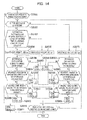
image generating unit 600 in the embodiment of the present invention is next described below.Fig. 18 is a flowchart of the process conducted by the bird's-eye image generator 610 in theimage generating unit 600. The bird's-eye image generator 610 first calculates the transformation matrix for transformingground 3D coordinates intocamera 3D coordinates (step S521). Theimage generator 610 also calculates the transformation matrix for transforming thecamera 3D coordinates intocamera screen 2D coordinates (step S522). Theimage generator 610 further uses the transformation matrices to generate a bird's-eye image as an image of thecamera screen 2D coordinates from the camera image (step S523). Next, theimage generator 610 places the bird's-eye image that it has generated through steps S521, S522, S523, around a dummy working-machine figure graphically representing the hydraulic excavator, and then after returning to step S521, repeats step S521 onward. In the present embodiment, the bird's-eye image by therearview camera 13a is placed at rear of the dummy working-machine figure, a bird's-eye image by the right-sideview camera 13b is placed at the right side of the dummy working-machine figure, and a bird's-eye image by the left-sideview camera 13c is placed at the left side of the dummy working-machine figure. A bird's-eye image of the hydraulic excavator periphery is thus generated. -
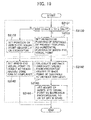
Fig. 19 is a flowchart of the process conducted in the bird's-eye visual-point setting unit 2100 (the bird's-eye position setter 2130 and bird's-eye height setter 2140) of theimage generating unit 600. After the risklevel setting unit 2000 has set the risk levels for the obstacles in the hazard zone, the bird's-eye position setter 2130 checks the contact risk levels of each obstacle (step S2131). If in step S2131 the contact risk levels of each obstacle are other than 1 to 5 (i.e., all risk levels are 0), the bird's-eye position setter 2130 sets the position of the bird's-eye visual point on the horizontal surface, as a central portion of the hydraulic excavator (step S2132), and advances the process to step S2142. If in step S2131 the contact risk levels of each obstacle include 1 to 5, the bird's-eye position setter 2130 sets a horizontal position of the obstacle having the highest level of a contact risk, as the position of the bird's-eye visual point on the horizontal surface (step S2133), and advances the process to step S2143. - In step S2142, the bird's-
eye height setter 2140 sets the height of the bird's-eye visual point to a value (set value) previously assigned so that the hazard zone can be displayed when looked down upon the hydraulic excavator from above the central portion (swinging center) thereof. After this, the bird's-eye height setter 2140 stores the horizontal position and height position of the bird's-eye visual point into the storage device and completes the process. - In step S2143, on the other hand, the bird's-
eye height setter 2140 calculates an absolute value of a distance from the central portion of the hydraulic excavator to the base point (described in step S502) of the obstacle having the highest level of a contact risk, the base point having been used in step S2133, and then calculates the height (e.g., 2 to 3 times that of the obstacle) of the bird's-eye visual point in proportion to the above-calculated value (step S2144). The proportionality constant by which the value calculated in step S2143 is to be multiplied in step S2144 can be such that the hazard zone can be displayed when looked down upon the central portion of the hydraulic excavator from above the obstacle of the highest contact risk level. After the bird's-eye height setter 2140 has calculated the height of the bird's-eye visual point in this way, thesetter 2140 stores the horizontal position of the bird's-eye visual point that was set in step S2133, and the height position set in step S2144, into the storage device and completes the process. - If the contact risk levels are already set through the above process, a bird's-eye visual point looking down towards the hydraulic excavator and the hazard zone is set up above the obstacle of the highest contact risk level of all those which the risk
level setting unit 2000 has set for each obstacle. If a contact risk level is not set, a bird's-eye visual point looking down towards the hydraulic excavator and the hazard zone from above the excavator is set up. -
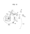
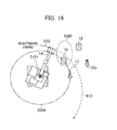
Fig. 20 is a conceptual diagram showing an example in which the bird's-eye visual-point setting unit 2100 sets a bird's-eye visual point. InFig. 20 , which assumes that the highest contact risk level is set for aperson 15d, ahorizontal position 2152 of theperson 15d is first set as that of the bird's-eye visual point in step S2133. In step S2143, a value of a difference (absolute value) between thecentral portion 2151 of the hydraulic excavator and thehorizontal position 2152 is calculated and then this calculated value is multiplied by a proportionality constant appropriate for a particular magnitude of the calculated value, to set theheight 2153 of the bird's-eye visual point. This allows position setting of the bird's-eye visual point (virtual camera) existing when themonitoring image generator 620 generates the monitoring image. -
Fig. 21 is a diagram showing a first example of a monitoring image which themonitoring image generator 620 in theimage generating unit 600 generates. In a scene thatFig. 21 shows, when the hydraulic excavator is swung rightward as denoted byreference number 612, the front working implement 1A also moves in a rightward direction in synchronization with the rightward swing. The risklevel setting unit 2000 then sets highestcontact risk level 5 for aperson 15c present at the right side of the front working implement 1A in thehazard zone 913. Next, the bird's-eye visual-point setting unit 2100 sets up the bird's-eye visual point atop theperson 15c and themonitoring image generator 620 generates, as amonitoring image 621, an image of the hydraulic excavator and hazard zone as viewed through the virtual camera from the bird's-eye visual point. Since the hydraulic excavator and the obstacle of the highest contact risk level will be displayed in the thus-generatedmonitoring image 621, the operator can instantly recognize the obstacle with which the hydraulic excavator is most likely to come into contact and the position of this obstacle relative to the excavator, without conducting a special judgment. In particular, this form of generating the monitoring image allows enlarged display of the situation in the operating direction (rightward swinging direction) of the hydraulic excavator, and hence, enlarged display of the most potentially hazardous obstacle (person 15c) present in the operating direction. In accordance with the present embodiment, therefore, working efficiency of the hydraulic excavator improves since the operator can instantly recognize the position of the most potentially hazardous obstacle relative to the excavator. -
Fig. 22 is a diagram showing a second example of a monitoring image which themonitoring image generator 620 in theimage generating unit 600 generates. In a scene thatFig. 22 shows, when thelower structure 1e is moved in reverse as denoted byreference number 617, the front working implement 1A and theupper structure 1d also move backward in synchronization with the reverse movement. The risklevel setting unit 2000 then sets highestcontact risk level 5 for aperson 15a present at rear of thelower structure 1e in thehazard zone 917. Next, the bird's-eye visual-point setting unit 2100 sets up the bird's-eye visual point atop theperson 15a and themonitoring image generator 620 generates an image of the hydraulic excavator and hazard zone as viewed from the bird's-eye visual point, as amonitoring image 631. In this example, therefore, the working efficiency of the hydraulic excavator also improves since the operator can instantly recognize the position of the most potentially hazardous obstacle relative to the excavator. -
Fig. 23 is a diagram showing a third example of a monitoring image which themonitoring image generator 620 in theimage generating unit 600 generates. As shown in this diagram, in order to improve the operator's visibility as to which obstacle is most likely to be hazardous, themonitoring image generator 620 depicts thewarning symbol 631 in superimposed form atop an obstacle (person 15c) for which the risklevel setting unit 2000 has set the highest level of a contact risk. In the example of this diagram, a substantially star-shaped figure is depicted as the warning symbol upon theperson 15c. - Additionally in the example of this diagram, in order to allow the operator to readily recognize from the monitoring image a vertical position at which the distal end of the
bucket 1c is likely to come into contact with an obstacle, thewarning symbol 631 is presented in superimposed form at the section with which the distal end of thebucket 1c is estimated to come into contact if the rightward swing is continued. That is, thewarning symbol 631 is presented on the head of theperson 16 in the example ofFig. 23 . When thewarning symbol 631 is to be made at the estimated contact section in this way, a comparison is conducted between the obstacle height that was set in step S2054, S2055, S2073 of the process conducted by the risklevel setting unit 2000, and the height of bucket distal end that has been calculated using the output signals θ1 to θ4 of theangle detectors 8a to 8d. For example, (1) if thebucket 1c is likely to come into contact with an upper half of the obstacle height, thewarning symbol 631 is made atop the obstacle (if a person, then the head), or (2) if thebucket 1c is likely to come into contact with a lower half of the obstacle height, thewarning symbol 631 is made at a lower part of the obstacle (if a person, then the trunk).Fig. 24 is a diagram showing a fourth example of a monitoring image which themonitoring image generator 620 in theimage generating unit 600 generates, themonitoring image 621 assuming that awarning symbol 632 is made at the trunk of aperson 15c. -
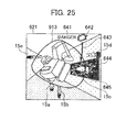
Fig. 25 is a diagram showing a fifth example of a monitoring image which themonitoring image generator 620 in theimage generating unit 600 generates. As shown in this diagram, if the type of obstacle for which the risklevel setting unit 2000 has set the highest level of a contact risk is a person, animage 645 representing a person is depicted in superimposed form upon awarning image 621 so as to surround the obstacle (person 15c) for which the highest level of a contact risk has been set. In the example ofFig. 25 , the image (photograph) representing theperson 15c extracted when the camera image is not converted into bird's-eye image form is depicted as the person-representingdisplay 645 in such a form as to surround theperson 15c. - If a monitoring image is generated using only a bird's-eye image, sections more distant from the
camera 13 are displayed in larger sizes, for which reason, the display of the object is most often distorted (e.g., a person's body regions closer to the head are displayed in more enlarged form). The obstacles existing at a long distance from thecamera 13 might therefore lack visibility since these obstacles may impart an uncomfortable feeling due to the distortion caused during conversion into bird's-eye image form. Accordingly if, as described above, theimage 645 representing a person is depicted in superimposed form upon the monitoring image, the operator can instantly understand where on the monitoring image a person is present. - For further improved visibility of the
person 15c present in theregion 644 of the circumscribed rectangle, theabove image 645 is preferably depicted in a conspicuous color that is readily identifiable to the operator and that doesn't exist in the image acquired by thecamera 13. Additionally, as shown in a previous example, a character string of "DANGER", 641, and anarrow 643 indicating the obstacle of the highest contact risk level may be displayed as a warning message or pictorial in superimposed form or a substantially star-shaped figure 642 may be displayed as a warning in superimposed form near thecharacter string 641, for even higher visibility. -
Fig. 26 is a diagram showing a sixth example of a monitoring image which themonitoring image generator 620 in theimage generating unit 600 generates. While theimage 645 acquired by thecamera 13 has been used as a person-representing image inFig. 25 , the example ofFig. 26 differs in that anillustration 655 representing an upper body of a person three-dimensionally is used as the person-representing image. Using an alternative method of representation in this way also enables the operator to instantly recognize where on the monitoring image a person is present. As in the example ofFig. 25 , acharacter string 651, a substantially star-shaped figure 652, anarrow 653, and/or the like may be displayed as a warning message or pictorial in superimposed form for even higher visibility. -
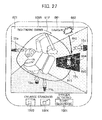
Fig. 27 is a diagram showing an example of a display screen of thedisplay device 1300 in the embodiment of the present invention. The display screen shown inFig. 27 includes amain display region 1005 for displaying a warning image generated by theimage generating unit 600, astart recording button 1001 for recording over a predetermined time the warning image displayed in themain display region 1005, an enlargedisplay button 1003 for displaying a monitoring image in enlarged form, and astandard display button 1004 for resetting the enlarging function of the enlargedisplay button 1003. In the warning image shown inFig. 27 , anillustration 665 representing a person's whole body three-dimensionally is displayed as an image representing a person. In addition, as in the examples ofFigs. 25 ,26 , acharacter string 661, a substantially star-shaped figure 662, anarrow 663, and/or the like may be displayed as a warning message or pictorial in further superimposed form. - If the
start recording button 1001 is provided as shown, the warning image displayed in themain display region 1005 can be optionally recorded when an obstacle (person 15c) with which the hydraulic excavator is likely to come into contact during operation is present around the excavator. Hence, even in case of an accident, the recorded image data can be used to investigate causes of the accident. Thedisplay device 1300 may be set so that even if thestart recording button 1001 is not pressed, the warning image will be recorded automatically when displayed in themain display region 1005. The same also applies to the enlarged display of the monitoring image; the monitoring image may be manually displayed in enlarged form by operation of the enlargedisplay button 1003 or automatically displayed in enlarged form when the warning image is displayed. Description of Reference Symbols -
- 1A
- Front working implement
- 1B
- Vehicle body
- 1a
- Boom
- 1b
- Arm
- 1c
- Bucket
- 1d
- Upper structure
- 1e
- Lower structure
- 1f
- Cabin
- 3a to 3c
- Hydraulic actuators
- 3e
- Traveling motor
- 8a, 8b, 8c, 8d
- Angle detectors
- 13a, 13b, 13c
- Cameras (Image sensors)
- 14a, 14b, 14c
- Millimeter-wave radars
- 15a, 15b, 15c, 15d, 15e
- Obstacles (Persons)
- 16, 17
- Obstacles (Objects)
- 30
- Operation device
- 400
- Obstacle detection unit
- 500
- Position calculating unit
- 600
- Image generating unit
- 610
- Bird's-eye image generator
- 620
- Monitoring image generator
- 700
- hazard zone calculating unit
- 800
- Determining unit
- 1300
- Display device
- 2000
- Risk level setting unit
- 2100
- Bird's-eye visual-point setting unit
- 2130
- Bird's-eye position setter
- 2140
- Bird's-eye height setter
Claims (5)
- A peripheral monitoring device for a working machine, comprising:imaging means that acquires an image of periphery of the working machine;obstacle detecting means that detects obstacles present around the working machine, by use of the acquired image;position calculating means that calculates positions of each of the detected obstacles relative to the working machine;hazard zone calculating means that calculates a hazard zone around the working machine, based upon at least one of an attitude and motion of the working machine;determining means that determines, by the calculated positions of the obstacles, whether further obstacles are present in the calculated hazard zone;risk level setting means that sets, for any obstacles determined by the determining means to be present in the hazard zone, a contact risk level based upon at least one of the type, position, and height of each obstacle that are obtained from the acquired image;image generating means that converts the acquired image into a bird's-eye image centering upon the working machine, and then generates an image inclusive of all elements of the working machine and hazard zone on the bird's-eye image by further imaging the bird's-eye image diagonally from above an obstacle for which the highest contact risk level is set by the risk level setting means; anddisplay means that displays the generated image.
- The peripheral monitoring device for a working machine according to claim 1, wherein:the risk level setting means further sets a contact risk level based upon at least one of the attitude and motion of the working machine.
- The peripheral monitoring device for a working machine according to claim 2, wherein:the working machine includes a traveling structure, a swinging structure swingably installed upon the traveling structure, and a front working implement connected to the swinging structure; andthe risk level setting means further sets the highest contact risk level for, among all obstacles of the same type, only an obstacle present at the position closest to the front working implement, in a direction that the swinging structure is going to swing.
- The peripheral monitoring device for a working machine according to any one of claims 1 to 3, wherein:in the generated image, the image generating means displays a warning image in superimposed form upon the obstacle having the highest contact risk level set by the risk level setting unit.
- The peripheral monitoring device for a working machine according to any one of claims 1 to 3, wherein:if the type of obstacle having the highest contact risk level set by the risk level setting unit is a person, the image generating means depicts an image representing a person, in superimposed form upon the obstacle in the generated image.
Applications Claiming Priority (1)
| Application Number | Priority Date | Filing Date | Title |
|---|---|---|---|
| PCT/JP2010/068718 WO2012053105A1 (en) | 2010-10-22 | 2010-10-22 | Work machine peripheral monitoring device |
Publications (3)
| Publication Number | Publication Date |
|---|---|
| EP2631374A1 true EP2631374A1 (en) | 2013-08-28 |
| EP2631374A4 EP2631374A4 (en) | 2016-01-20 |
| EP2631374B1 EP2631374B1 (en) | 2020-09-30 |
Family
ID=45974838
Family Applications (1)
| Application Number | Title | Priority Date | Filing Date |
|---|---|---|---|
| EP10858659.5A Active EP2631374B1 (en) | 2010-10-22 | 2010-10-22 | Work machine peripheral monitoring device |
Country Status (6)
| Country | Link |
|---|---|
| US (1) | US9113047B2 (en) |
| EP (1) | EP2631374B1 (en) |
| JP (1) | JP5667638B2 (en) |
| KR (1) | KR101751405B1 (en) |
| CN (1) | CN103180522B (en) |
| WO (1) | WO2012053105A1 (en) |
Cited By (25)
| Publication number | Priority date | Publication date | Assignee | Title |
|---|---|---|---|---|
| WO2014121810A1 (en) * | 2013-02-06 | 2014-08-14 | Volvo Construction Equipment Germany GmbH | Construction machine having a monitoring device |
| EP2937811A1 (en) * | 2014-04-25 | 2015-10-28 | Hitachi Construction Machinery Co., Ltd. | Vehicle peripheral obstacle notification system |
| US20160006947A1 (en) * | 2013-02-08 | 2016-01-07 | Hitachi Construction Machinery Co., Ltd. | Surroundings monitoring device for slewing-type work machine |
| EP3035134A1 (en) * | 2014-12-15 | 2016-06-22 | Siemens Aktiengesellschaft | Dynamic virtual fencing for a hazardous environment |
| EP3064646A1 (en) * | 2015-03-04 | 2016-09-07 | Dynapac GmbH | Road construction machine and method for operating a self-propelled road construction machine |
| EP3141663A1 (en) * | 2015-03-16 | 2017-03-15 | Doosan Infracore Co., Ltd. | Method of displaying a dead zone of a construction machine and apparatus for performing the same |
| EP3110142A4 (en) * | 2014-02-17 | 2017-11-29 | Hitachi Construction Machinery Co., Ltd. | Monitoring image display device of industrial machine |
| EP3378996A1 (en) * | 2017-03-22 | 2018-09-26 | Kobelco Construction Machinery Co., Ltd. | Construction machine with collision preventing system |
| DE102017106893A1 (en) * | 2017-03-30 | 2018-10-04 | Komatsu Ltd. | working vehicle |
| EP3409843A1 (en) * | 2017-05-30 | 2018-12-05 | Kobelco Construction Machinery Co., Ltd. | Working machine |
| EP3409841A4 (en) * | 2016-03-02 | 2019-03-20 | Kabushiki Kaisha Kobe Seiko Sho (Kobe Steel, Ltd.) | Interference prevention device for construction machinery |
| EP3412839A4 (en) * | 2016-09-28 | 2019-09-25 | Hitachi Construction Machinery Co., Ltd | Work machine |
| WO2019210931A1 (en) * | 2018-04-30 | 2019-11-07 | Volvo Construction Equipment Ab | System and method for selectively displaying image data in a working machine |
| EP3594417A1 (en) * | 2018-07-12 | 2020-01-15 | Novatron Oy | Control system for controlling a tool of a machine |
| EP3021178B1 (en) * | 2014-11-14 | 2020-02-19 | Caterpillar Inc. | System using radar apparatus for assisting a user of a machine of a kind comprising a body and an implement |
| EP3495570A4 (en) * | 2017-03-31 | 2020-03-25 | Hitachi Construction Machinery Co., Ltd. | Device to monitor area around working machine |
| FR3095392A1 (en) * | 2019-04-24 | 2020-10-30 | Option Automatismes | Anti-collision system for construction machinery, and construction machinery equipped with such an anti-collision system |
| EP3572590A4 (en) * | 2018-03-14 | 2020-12-09 | Hitachi Construction Machinery Co., Ltd. | Work machine |
| EP3722519A4 (en) * | 2017-12-04 | 2021-04-21 | Sumitomo Heavy Industries, Ltd. | Surrounding-area monitoring device, information processing terminal, information processing device, and information processing program |
| EP3789546A4 (en) * | 2018-07-12 | 2021-08-25 | Kobelco Construction Machinery Co., Ltd. | Safety device for revolving-type work machine |
| EP3951089A4 (en) * | 2019-03-30 | 2022-09-14 | Sumitomo Construction Machinery Co., Ltd. | Shovel excavator and construction system |
| EP4050162A4 (en) * | 2019-12-10 | 2023-01-18 | Kobelco Construction Machinery Co., Ltd. | Remote operation assistance system for work machine |
| US11693411B2 (en) | 2020-02-27 | 2023-07-04 | Deere & Company | Machine dump body control using object detection |
| US11821167B2 (en) | 2019-09-05 | 2023-11-21 | Deere & Company | Excavator with improved movement sensing |
| US11970839B2 (en) | 2019-09-05 | 2024-04-30 | Deere & Company | Excavator with improved movement sensing |
Families Citing this family (112)
| Publication number | Priority date | Publication date | Assignee | Title |
|---|---|---|---|---|
| US9230419B2 (en) | 2010-07-27 | 2016-01-05 | Rite-Hite Holding Corporation | Methods and apparatus to detect and warn proximate entities of interest |
| US8768583B2 (en) | 2012-03-29 | 2014-07-01 | Harnischfeger Technologies, Inc. | Collision detection and mitigation systems and methods for a shovel |
| JP5456123B1 (en) | 2012-09-20 | 2014-03-26 | 株式会社小松製作所 | Work vehicle periphery monitoring system and work vehicle |
| JP5969379B2 (en) * | 2012-12-21 | 2016-08-17 | 住友建機株式会社 | Excavator and excavator control method |
| JP6302622B2 (en) * | 2013-03-19 | 2018-03-28 | 住友重機械工業株式会社 | Perimeter monitoring equipment for work machines |
| US20140293047A1 (en) * | 2013-04-02 | 2014-10-02 | Caterpillar Inc. | System for generating overhead view of machine |
| JP6091977B2 (en) * | 2013-04-22 | 2017-03-08 | 日立建機株式会社 | Construction machinery |
| JP6386213B2 (en) * | 2013-05-16 | 2018-09-05 | 住友建機株式会社 | Excavator |
| CN105009572B (en) * | 2013-08-26 | 2018-04-03 | 日立建机株式会社 | The surroundings monitoring apparatus of Work machine |
| WO2015040764A1 (en) * | 2013-12-11 | 2015-03-26 | 株式会社小松製作所 | Work machine, management system and management method |
| JP6267972B2 (en) * | 2014-01-23 | 2018-01-24 | 日立建機株式会社 | Work machine ambient monitoring device |
| JP6433664B2 (en) * | 2014-02-14 | 2018-12-05 | 国立大学法人 東京大学 | Overhead image display device for construction machinery |
| JP6962667B2 (en) * | 2014-03-27 | 2021-11-05 | 住友建機株式会社 | Excavator and its control method |
| US10228232B2 (en) * | 2014-04-14 | 2019-03-12 | Caterpillar Inc. | Operator assistance system |
| DE102014107235A1 (en) * | 2014-05-22 | 2015-11-26 | Dr. Ing. H.C. F. Porsche Aktiengesellschaft | A method of displaying a vehicle environment on a display device; a display device; a system of a plurality of image capture units and a display device; a computer program |
| WO2015186588A1 (en) * | 2014-06-03 | 2015-12-10 | 住友重機械工業株式会社 | Human detection system for construction machine |
| EP3154024B1 (en) * | 2014-06-03 | 2023-08-09 | Sumitomo Heavy Industries, Ltd. | Human detection system for construction machine |
| KR102190891B1 (en) * | 2014-09-22 | 2020-12-14 | 에스엘 주식회사 | Environment monitoring apparatus and method for vehicle |
| JP6407663B2 (en) * | 2014-10-30 | 2018-10-17 | 日立建機株式会社 | Work support image generation apparatus and work machine control system including the same |
| EP3020868B1 (en) * | 2014-11-14 | 2020-11-04 | Caterpillar Inc. | Machine of a kind comprising a body and an implement movable relative to the body with a system for assisting a user of the machine |
| EP3168373B1 (en) * | 2014-11-14 | 2019-07-10 | Caterpillar Inc. | A machine with a system for improving safety |
| US9881422B2 (en) * | 2014-12-04 | 2018-01-30 | Htc Corporation | Virtual reality system and method for controlling operation modes of virtual reality system |
| JP6777375B2 (en) | 2015-03-05 | 2020-10-28 | 株式会社小松製作所 | Work machine image display system, work machine remote control system and work machine |
| WO2016157462A1 (en) * | 2015-03-31 | 2016-10-06 | 株式会社小松製作所 | Work-machine periphery monitoring device |
| US9614845B2 (en) | 2015-04-15 | 2017-04-04 | Early Warning Services, Llc | Anonymous authentication and remote wireless token access |
| JP6559464B2 (en) * | 2015-05-14 | 2019-08-14 | 日立建機株式会社 | Work vehicle ambient monitoring device |
| KR101683677B1 (en) * | 2015-07-10 | 2016-12-20 | 엘아이지넥스원 주식회사 | Apparatus and method for controlling around view of vehicle |
| CN107923745B (en) * | 2015-08-26 | 2021-07-23 | 住友建机株式会社 | Measuring device for excavator |
| US10084782B2 (en) | 2015-09-21 | 2018-09-25 | Early Warning Services, Llc | Authenticator centralization and protection |
| CN106797449B (en) * | 2015-09-30 | 2019-12-03 | 株式会社小松制作所 | The periphery monitoring apparatus of track-type work machine |
| JP6925775B2 (en) * | 2015-10-05 | 2021-08-25 | 株式会社小松製作所 | Construction management system |
| DE102015221340B4 (en) | 2015-10-30 | 2021-02-25 | Conti Temic Microelectronic Gmbh | Device and method for providing a vehicle environment view for a vehicle |
| US9787951B2 (en) * | 2015-12-18 | 2017-10-10 | Serge Kannon | Vehicle proximity warning system |
| EP3399110B1 (en) * | 2015-12-28 | 2021-02-17 | Sumitomo (S.H.I.) Construction Machinery Co., Ltd. | Excavator |
| EP3246474B1 (en) * | 2016-03-29 | 2021-11-10 | Komatsu Ltd. | Work vehicle |
| CN106193144A (en) * | 2016-07-01 | 2016-12-07 | 蔡雄 | A kind of load wagon possessing Road Detection function |
| JP6812432B2 (en) * | 2016-07-05 | 2021-01-13 | 住友建機株式会社 | Excavator |
| AU2017204001B2 (en) * | 2016-07-06 | 2022-06-09 | Caterpillar Inc. | Operator assistance system |
| CN115092032A (en) * | 2016-07-20 | 2022-09-23 | 普瑞诺斯有限公司 | Tracked vehicle with rotatable superstructure and method therefor |
| KR101991153B1 (en) * | 2016-08-02 | 2019-06-19 | 김필주 | Stricture prevention device for construction equipment |
| AU2016216541B2 (en) | 2016-08-15 | 2018-08-16 | Bucher Municipal Pty Ltd | Refuse collection vehicle and system therefor |
| JP6832548B2 (en) * | 2016-08-31 | 2021-02-24 | 株式会社小松製作所 | Work machine image display system, work machine remote control system, work machine and work machine image display method |
| JP2018036937A (en) * | 2016-09-01 | 2018-03-08 | 住友電気工業株式会社 | Image processing device, image processing system, image processing program and label |
| JP6794193B2 (en) * | 2016-09-02 | 2020-12-02 | 株式会社小松製作所 | Image display system for work machines |
| JP6923144B2 (en) * | 2016-09-02 | 2021-08-18 | 株式会社小松製作所 | Image display system for work machines |
| US10106951B2 (en) * | 2016-09-21 | 2018-10-23 | Deere & Company | System and method for automatic dump control |
| JP6730606B2 (en) * | 2016-11-25 | 2020-07-29 | 株式会社Jvcケンウッド | Overhead video generation device, overhead video generation system, overhead video generation method and program |
| CN109790701B (en) * | 2016-12-06 | 2022-02-22 | 住友建机株式会社 | Construction machine |
| US10668854B2 (en) * | 2017-02-09 | 2020-06-02 | Komatsu Ltd. | Work vehicle and display device |
| WO2018151280A1 (en) * | 2017-02-17 | 2018-08-23 | 住友重機械工業株式会社 | Work machine surroundings monitoring system |
| JP6805883B2 (en) * | 2017-02-28 | 2020-12-23 | コベルコ建機株式会社 | Construction machinery |
| JP6715205B2 (en) * | 2017-03-29 | 2020-07-01 | 日立建機株式会社 | Work machine surrounding image display device |
| JP6859812B2 (en) * | 2017-03-31 | 2021-04-14 | コベルコ建機株式会社 | Interference monitoring device |
| JP6930261B2 (en) * | 2017-07-14 | 2021-09-01 | コベルコ建機株式会社 | Construction machinery |
| JP6960802B2 (en) * | 2017-08-24 | 2021-11-05 | 日立建機株式会社 | Surrounding monitoring device for work machines |
| CN110249203B (en) | 2017-09-01 | 2022-03-15 | 株式会社小松制作所 | Work machine surveying system, work machine, and work machine surveying method |
| KR102159066B1 (en) * | 2017-09-07 | 2020-09-23 | 히다찌 겐끼 가부시키가이샤 | Construction machinery |
| JP6927821B2 (en) * | 2017-09-15 | 2021-09-01 | 株式会社小松製作所 | Display system and display device |
| US10647282B2 (en) | 2017-11-06 | 2020-05-12 | Magna Electronics Inc. | Vehicle vision system with undercarriage cameras |
| JP7039983B2 (en) * | 2017-12-13 | 2022-03-23 | コベルコ建機株式会社 | Alert device for construction machinery |
| EP3499405A1 (en) | 2017-12-13 | 2019-06-19 | My Virtual Reality Software AS | Method and device for augmenting a person's view of a mining vehicle on a mining worksite in real-time |
| JP6740259B2 (en) * | 2018-01-04 | 2020-08-12 | 住友重機械工業株式会社 | Work machine |
| KR102023270B1 (en) * | 2018-02-07 | 2019-09-20 | 중앙대학교 산학협력단 | Construction equipment real-time safety monitoring apparatus and method |
| JP7232437B2 (en) * | 2018-02-19 | 2023-03-03 | 国立大学法人 東京大学 | WORK VEHICLE DISPLAY SYSTEM AND GENERATION METHOD |
| JPWO2019168122A1 (en) * | 2018-02-28 | 2021-03-04 | 住友建機株式会社 | Excavator |
| WO2019189030A1 (en) * | 2018-03-26 | 2019-10-03 | 住友建機株式会社 | Excavator |
| GB2586712B (en) * | 2018-03-28 | 2021-12-22 | Mitsubishi Electric Corp | Image processing device, image processing method, and image processing program |
| KR102652955B1 (en) * | 2018-03-30 | 2024-03-28 | 스미토모 겐키 가부시키가이샤 | shovel |
| JP7070047B2 (en) * | 2018-04-26 | 2022-05-18 | コベルコ建機株式会社 | Swing control device for swivel work machines |
| CN108608980A (en) * | 2018-06-05 | 2018-10-02 | 徐工集团工程机械有限公司 | Engineering truck and its control method |
| JP7080750B2 (en) * | 2018-06-29 | 2022-06-06 | 株式会社小松製作所 | Display control system, remote control system, display control device, and display control method |
| JP7285051B2 (en) * | 2018-06-29 | 2023-06-01 | 株式会社小松製作所 | Display control device and display control method |
| JP7058569B2 (en) * | 2018-07-19 | 2022-04-22 | 日立建機株式会社 | Work machine |
| EP3832034B1 (en) * | 2018-07-31 | 2023-08-23 | Sumitomo (S.H.I.) Construction Machinery Co., Ltd. | Excavator |
| JP2019004484A (en) * | 2018-08-07 | 2019-01-10 | 住友建機株式会社 | Shovel |
| JP7296340B2 (en) * | 2018-08-07 | 2023-06-22 | 住友建機株式会社 | Excavator |
| JP2020051092A (en) * | 2018-09-26 | 2020-04-02 | コベルコ建機株式会社 | Work machine information display system |
| JP7058582B2 (en) * | 2018-09-27 | 2022-04-22 | 日立建機株式会社 | Work machine |
| JP7133428B2 (en) * | 2018-10-15 | 2022-09-08 | 日立建機株式会社 | excavator |
| DE102018220395A1 (en) * | 2018-11-28 | 2020-05-28 | Zf Friedrichshafen Ag | Direction-dependent control of a sensor arrangement for monitoring a work area of a work machine |
| JP7130547B2 (en) * | 2018-12-26 | 2022-09-05 | 住友建機株式会社 | Excavator and perimeter monitoring device for excavator |
| CN109403946B (en) * | 2018-12-27 | 2022-07-29 | 北京三一智造科技有限公司 | Rotary drilling rig rotation animation display method and device and rotary drilling rig |
| JP7454461B2 (en) * | 2019-01-28 | 2024-03-22 | 住友重機械工業株式会社 | excavator |
| JP2019071677A (en) * | 2019-01-28 | 2019-05-09 | 住友重機械工業株式会社 | Shovel |
| EP3951083A4 (en) | 2019-04-05 | 2022-11-30 | Volvo Construction Equipment AB | Construction equipment |
| JP7189074B2 (en) * | 2019-04-26 | 2022-12-13 | 日立建機株式会社 | working machine |
| KR102625693B1 (en) * | 2019-05-20 | 2024-01-17 | 에이치디현대건설기계 주식회사 | System for obstacle collision avoidance of construction equipment |
| KR102018119B1 (en) * | 2019-05-30 | 2019-09-04 | 최중경 | A method of preventing safety-accident on the iron scrap processing site |
| WO2020242065A1 (en) * | 2019-05-31 | 2020-12-03 | 주식회사 라운지랩 | Robot movement control method based on risk level determination and mobile robot device using same |
| DE112020002887T5 (en) * | 2019-07-18 | 2022-04-07 | Komatsu Ltd. | Work vehicle display system and work vehicle display method |
| CN114269992B (en) * | 2019-09-30 | 2023-10-13 | 株式会社小松制作所 | Work machine and control method for work machine |
| US11320830B2 (en) | 2019-10-28 | 2022-05-03 | Deere & Company | Probabilistic decision support for obstacle detection and classification in a working area |
| JP7153627B2 (en) * | 2019-10-31 | 2022-10-14 | 日立建機株式会社 | Work machine and perimeter monitoring system |
| JP7217691B2 (en) * | 2019-10-31 | 2023-02-03 | 日立建機株式会社 | construction machinery |
| JP7255454B2 (en) * | 2019-11-07 | 2023-04-11 | コベルコ建機株式会社 | Surrounding monitoring device for working machines |
| JP7325308B2 (en) | 2019-11-19 | 2023-08-14 | ルネサスエレクトロニクス株式会社 | Image processing device and image processing method |
| JP7341396B2 (en) * | 2019-12-03 | 2023-09-11 | コベルコ建機株式会社 | Remote operation support server and remote operation support system |
| WO2021193450A1 (en) * | 2020-03-25 | 2021-09-30 | 住友重機械工業株式会社 | Construction machine, management system for construction machine, machine learning device, and management system for work site of construction machine |
| JP7237882B2 (en) * | 2020-04-07 | 2023-03-13 | 住友建機株式会社 | Excavator |
| JP7257357B2 (en) * | 2020-04-28 | 2023-04-13 | 住友重機械工業株式会社 | Excavators and systems for excavators |
| US11891782B2 (en) * | 2020-04-30 | 2024-02-06 | Deere & Company | Ground engaging tool control system and method |
| CN111595255A (en) * | 2020-05-14 | 2020-08-28 | 南京航空航天大学 | Tunnel defect real-time prompting device and prompting method |
| DE102020206373A1 (en) | 2020-05-20 | 2021-11-25 | Robert Bosch Gesellschaft mit beschränkter Haftung | Method for avoiding a collision of a work tool of a work machine with obstacles located in the vicinity of the work machine |
| US11773567B2 (en) | 2020-07-22 | 2023-10-03 | Baidu Usa Llc | Engineering machinery equipment, and method, system, and storage medium for safety control thereof |
| CN114445989A (en) * | 2020-11-06 | 2022-05-06 | 湖南五新模板有限公司 | Trestle safety protection system and method and trestle |
| JP2022076406A (en) * | 2020-11-09 | 2022-05-19 | 日本電気株式会社 | Control device, control system, and control method |
| DE102020214291B3 (en) * | 2020-11-13 | 2022-03-17 | Tadano Faun Gmbh | Crane, in particular mobile crane |
| KR102575009B1 (en) * | 2020-12-22 | 2023-09-07 | (주)다울 | Smart safety administration system for forklift truck and mehtod thereof |
| CN113012315B (en) * | 2021-02-23 | 2022-07-05 | 浙江三一装备有限公司 | Safety monitoring system and method for working machine and working machine |
| WO2022202855A1 (en) * | 2021-03-22 | 2022-09-29 | 住友建機株式会社 | Construction machine and construction machine assisting method |
| US11840823B2 (en) | 2021-03-30 | 2023-12-12 | Darrell Cobb | Backhoe camera assembly |
| US20230339402A1 (en) * | 2022-04-21 | 2023-10-26 | Deere & Company | Selectively utilizing multiple imaging devices to maintain a view of an area of interest proximate a work vehicle |
Family Cites Families (17)
| Publication number | Priority date | Publication date | Assignee | Title |
|---|---|---|---|---|
| JP3679848B2 (en) * | 1995-12-27 | 2005-08-03 | 日立建機株式会社 | Construction machine working range restriction control device |
| US6643576B1 (en) * | 2000-11-15 | 2003-11-04 | Integrinautics Corporation | Rapid adjustment of trajectories for land vehicles |
| JP2004343297A (en) * | 2003-05-14 | 2004-12-02 | Hitachi Constr Mach Co Ltd | Periphery monitoring device of construction machine |
| DE102006042547A1 (en) * | 2006-09-11 | 2008-03-27 | Bartec Gmbh | System for monitoring a danger zone, in particular a vehicle |
| JP4996928B2 (en) * | 2007-01-05 | 2012-08-08 | 日立建機株式会社 | Work machine ambient monitoring device |
| JP4847913B2 (en) * | 2007-03-30 | 2011-12-28 | 日立建機株式会社 | Work machine periphery monitoring device |
| CN101070706A (en) * | 2007-05-29 | 2007-11-14 | 三一重机有限公司 | Hydraulic-digger obstruction-avoiding control system and method |
| JP2009013633A (en) * | 2007-07-03 | 2009-01-22 | Hitachi Constr Mach Co Ltd | Safety device of construction machine |
| JP5064976B2 (en) | 2007-11-12 | 2012-10-31 | クラリオン株式会社 | Work safety monitoring system for construction and civil engineering vehicles |
| JP4977667B2 (en) * | 2008-09-02 | 2012-07-18 | 日立建機株式会社 | Visual aid for work machine |
| JP5068779B2 (en) * | 2009-02-27 | 2012-11-07 | 現代自動車株式会社 | Vehicle surroundings overhead image display apparatus and method |
| JP5227841B2 (en) * | 2009-02-27 | 2013-07-03 | 日立建機株式会社 | Ambient monitoring device |
| JP5165631B2 (en) * | 2009-04-14 | 2013-03-21 | 現代自動車株式会社 | Vehicle surrounding image display system |
| US20110001819A1 (en) * | 2009-07-02 | 2011-01-06 | Sanyo Electric Co., Ltd. | Image Processing Apparatus |
| TWI392366B (en) * | 2009-12-31 | 2013-04-01 | Ind Tech Res Inst | Method and system for generating surrounding seamless bird-view image with distance interface |
| JP5397697B2 (en) * | 2010-03-12 | 2014-01-22 | アイシン精機株式会社 | Image control device |
| EP2570556B1 (en) * | 2010-06-18 | 2021-04-28 | Hitachi Construction Machinery Co., Ltd. | Device for monitoring area around work machine |
-
2010
- 2010-10-22 US US13/880,490 patent/US9113047B2/en not_active Expired - Fee Related
- 2010-10-22 JP JP2012539546A patent/JP5667638B2/en not_active Expired - Fee Related
- 2010-10-22 CN CN201080069736.4A patent/CN103180522B/en not_active Expired - Fee Related
- 2010-10-22 WO PCT/JP2010/068718 patent/WO2012053105A1/en active Application Filing
- 2010-10-22 KR KR1020137009804A patent/KR101751405B1/en active IP Right Grant
- 2010-10-22 EP EP10858659.5A patent/EP2631374B1/en active Active
Cited By (38)
| Publication number | Priority date | Publication date | Assignee | Title |
|---|---|---|---|---|
| WO2014121810A1 (en) * | 2013-02-06 | 2014-08-14 | Volvo Construction Equipment Germany GmbH | Construction machine having a monitoring device |
| US20160006947A1 (en) * | 2013-02-08 | 2016-01-07 | Hitachi Construction Machinery Co., Ltd. | Surroundings monitoring device for slewing-type work machine |
| US10506179B2 (en) | 2013-02-08 | 2019-12-10 | Hitachi Construction Machinery Co., Ltd. | Surrounding monitoring device for slewing-type work machine |
| US20190037148A1 (en) * | 2013-02-08 | 2019-01-31 | Hitachi Construction Machinery Co., Ltd. | Surrounding monitoring device for slewing-type work machine |
| EP3110142A4 (en) * | 2014-02-17 | 2017-11-29 | Hitachi Construction Machinery Co., Ltd. | Monitoring image display device of industrial machine |
| EP2937811A1 (en) * | 2014-04-25 | 2015-10-28 | Hitachi Construction Machinery Co., Ltd. | Vehicle peripheral obstacle notification system |
| US9463741B2 (en) | 2014-04-25 | 2016-10-11 | Hitachi Construction Machinery Co., Ltd. | Vehicle peripheral obstacle notification system |
| EP3021178B1 (en) * | 2014-11-14 | 2020-02-19 | Caterpillar Inc. | System using radar apparatus for assisting a user of a machine of a kind comprising a body and an implement |
| EP3035134A1 (en) * | 2014-12-15 | 2016-06-22 | Siemens Aktiengesellschaft | Dynamic virtual fencing for a hazardous environment |
| US10417892B2 (en) | 2014-12-15 | 2019-09-17 | Siemens Aktiengesellschaft | Dynamic virtual fencing for a hazardous environment |
| EP3064646A1 (en) * | 2015-03-04 | 2016-09-07 | Dynapac GmbH | Road construction machine and method for operating a self-propelled road construction machine |
| US10060098B2 (en) | 2015-03-16 | 2018-08-28 | Doosan Infracore Co., Ltd. | Method of displaying a dead zone of a construction machine and apparatus for performing the same |
| EP3141663A1 (en) * | 2015-03-16 | 2017-03-15 | Doosan Infracore Co., Ltd. | Method of displaying a dead zone of a construction machine and apparatus for performing the same |
| US11111654B2 (en) | 2016-03-02 | 2021-09-07 | Kabushiki Kaisha Kobe Seiko Sho (Kobe Steel, Ltd.) | Interference prevention device for construction machinery |
| EP3409841A4 (en) * | 2016-03-02 | 2019-03-20 | Kabushiki Kaisha Kobe Seiko Sho (Kobe Steel, Ltd.) | Interference prevention device for construction machinery |
| US10590628B2 (en) | 2016-09-28 | 2020-03-17 | Hitachi Construction Machinery Co., Ltd. | Work machine |
| EP3412839A4 (en) * | 2016-09-28 | 2019-09-25 | Hitachi Construction Machinery Co., Ltd | Work machine |
| US10876273B2 (en) | 2017-03-22 | 2020-12-29 | Kobelco Construction Machinery Co., Ltd. | Construction machine |
| EP3378996A1 (en) * | 2017-03-22 | 2018-09-26 | Kobelco Construction Machinery Co., Ltd. | Construction machine with collision preventing system |
| DE102017106893B4 (en) | 2017-03-30 | 2020-07-30 | Komatsu Ltd. | Work vehicle |
| DE102017106893A1 (en) * | 2017-03-30 | 2018-10-04 | Komatsu Ltd. | working vehicle |
| EP3495570A4 (en) * | 2017-03-31 | 2020-03-25 | Hitachi Construction Machinery Co., Ltd. | Device to monitor area around working machine |
| EP3409843A1 (en) * | 2017-05-30 | 2018-12-05 | Kobelco Construction Machinery Co., Ltd. | Working machine |
| US11149406B2 (en) | 2017-05-30 | 2021-10-19 | Kobelco Construction Machinery Co., Ltd. | Working machine |
| EP3722519A4 (en) * | 2017-12-04 | 2021-04-21 | Sumitomo Heavy Industries, Ltd. | Surrounding-area monitoring device, information processing terminal, information processing device, and information processing program |
| EP3572590A4 (en) * | 2018-03-14 | 2020-12-09 | Hitachi Construction Machinery Co., Ltd. | Work machine |
| CN112041508A (en) * | 2018-04-30 | 2020-12-04 | 沃尔沃建筑设备公司 | System and method for selectively displaying image data in a work machine |
| WO2019210931A1 (en) * | 2018-04-30 | 2019-11-07 | Volvo Construction Equipment Ab | System and method for selectively displaying image data in a working machine |
| EP3594417A1 (en) * | 2018-07-12 | 2020-01-15 | Novatron Oy | Control system for controlling a tool of a machine |
| US11618120B2 (en) | 2018-07-12 | 2023-04-04 | Novatron Oy | Control system for controlling a tool of a machine |
| EP3789546A4 (en) * | 2018-07-12 | 2021-08-25 | Kobelco Construction Machinery Co., Ltd. | Safety device for revolving-type work machine |
| EP3951089A4 (en) * | 2019-03-30 | 2022-09-14 | Sumitomo Construction Machinery Co., Ltd. | Shovel excavator and construction system |
| FR3095392A1 (en) * | 2019-04-24 | 2020-10-30 | Option Automatismes | Anti-collision system for construction machinery, and construction machinery equipped with such an anti-collision system |
| EP3744904A1 (en) * | 2019-04-24 | 2020-12-02 | Option Automatismes | Anti-collision system for a construction machine and construction machine provided with such an anti-collision system |
| US11821167B2 (en) | 2019-09-05 | 2023-11-21 | Deere & Company | Excavator with improved movement sensing |
| US11970839B2 (en) | 2019-09-05 | 2024-04-30 | Deere & Company | Excavator with improved movement sensing |
| EP4050162A4 (en) * | 2019-12-10 | 2023-01-18 | Kobelco Construction Machinery Co., Ltd. | Remote operation assistance system for work machine |
| US11693411B2 (en) | 2020-02-27 | 2023-07-04 | Deere & Company | Machine dump body control using object detection |
Also Published As
| Publication number | Publication date |
|---|---|
| EP2631374A4 (en) | 2016-01-20 |
| KR101751405B1 (en) | 2017-06-27 |
| JPWO2012053105A1 (en) | 2014-02-24 |
| CN103180522A (en) | 2013-06-26 |
| EP2631374B1 (en) | 2020-09-30 |
| JP5667638B2 (en) | 2015-02-12 |
| US20130222573A1 (en) | 2013-08-29 |
| US9113047B2 (en) | 2015-08-18 |
| WO2012053105A1 (en) | 2012-04-26 |
| CN103180522B (en) | 2016-01-13 |
| KR20140009148A (en) | 2014-01-22 |
Similar Documents
| Publication | Publication Date | Title |
|---|---|---|
| EP2631374B1 (en) | Work machine peripheral monitoring device | |
| JP5227841B2 (en) | Ambient monitoring device | |
| EP2481637B1 (en) | Parking Assistance System and Method | |
| EP2723069B1 (en) | Vehicle periphery monitoring device | |
| KR101123738B1 (en) | System and method for monitoring safe operation of heavy machinery | |
| JP4951639B2 (en) | Work machine with ambient monitoring device | |
| US20140118533A1 (en) | Operational stability enhancing device for construction machinery | |
| EP2784763A1 (en) | Vehicle periphery monitoring device | |
| US10044933B2 (en) | Periphery monitoring device for work machine | |
| TW201103787A (en) | Obstacle determination system and method utilizing bird's-eye images | |
| JP2011188335A (en) | Vehicle surroundings monitoring device | |
| EP3139340B1 (en) | System and method for visibility enhancement | |
| US20160301864A1 (en) | Imaging processing system for generating a surround-view image | |
| US20160301863A1 (en) | Image processing system for generating a surround-view image | |
| KR101998300B1 (en) | Working environment monitoring apparatus and working environment monitoring method performed in the same | |
| JP2017046277A (en) | Periphery monitoring device for work machine | |
| WO2019034916A1 (en) | System and method for presentation and control of virtual camera image for a vehicle | |
| CN108290499B (en) | Driver assistance system with adaptive ambient image data processing | |
| KR20210034450A (en) | Apparatus for generating front image for construction equipment | |
| JP6368503B2 (en) | Obstacle monitoring system and program | |
| KR101797750B1 (en) | Apparatus and method for generating bird eye view image | |
| WO2023189216A1 (en) | Work assistance system | |
| CN217945043U (en) | Vehicle and apparatus for determining objects around vehicle | |
| US20220375157A1 (en) | Overturning-risk presentation device and overturning-risk presentation method | |
| US20220356680A1 (en) | Operation area presentation device and operation area presentation method |
Legal Events
| Date | Code | Title | Description |
|---|---|---|---|
| PUAI | Public reference made under article 153(3) epc to a published international application that has entered the european phase |
Free format text: ORIGINAL CODE: 0009012 |
|
| 17P | Request for examination filed |
Effective date: 20130522 |
|
| AK | Designated contracting states |
Kind code of ref document: A1 Designated state(s): AL AT BE BG CH CY CZ DE DK EE ES FI FR GB GR HR HU IE IS IT LI LT LU LV MC MK MT NL NO PL PT RO RS SE SI SK SM TR |
|
| DAX | Request for extension of the european patent (deleted) | ||
| RA4 | Supplementary search report drawn up and despatched (corrected) |
Effective date: 20151222 |
|
| RIC1 | Information provided on ipc code assigned before grant |
Ipc: G05B 9/02 20060101ALI20151216BHEP Ipc: E02F 9/26 20060101ALI20151216BHEP Ipc: H04N 7/18 20060101ALI20151216BHEP Ipc: E02F 9/24 20060101AFI20151216BHEP Ipc: F04B 49/06 20060101ALI20151216BHEP |
|
| GRAP | Despatch of communication of intention to grant a patent |
Free format text: ORIGINAL CODE: EPIDOSNIGR1 |
|
| STAA | Information on the status of an ep patent application or granted ep patent |
Free format text: STATUS: GRANT OF PATENT IS INTENDED |
|
| INTG | Intention to grant announced |
Effective date: 20200417 |
|
| GRAS | Grant fee paid |
Free format text: ORIGINAL CODE: EPIDOSNIGR3 |
|
| GRAA | (expected) grant |
Free format text: ORIGINAL CODE: 0009210 |
|
| STAA | Information on the status of an ep patent application or granted ep patent |
Free format text: STATUS: THE PATENT HAS BEEN GRANTED |
|
| RAP1 | Party data changed (applicant data changed or rights of an application transferred) |
Owner name: HITACHI CONSTRUCTION MACHINERY CO., LTD. |
|
| AK | Designated contracting states |
Kind code of ref document: B1 Designated state(s): AL AT BE BG CH CY CZ DE DK EE ES FI FR GB GR HR HU IE IS IT LI LT LU LV MC MK MT NL NO PL PT RO RS SE SI SK SM TR |
|
| REG | Reference to a national code |
Ref country code: CH Ref legal event code: EP Ref country code: GB Ref legal event code: FG4D |
|
| REG | Reference to a national code |
Ref country code: AT Ref legal event code: REF Ref document number: 1318921 Country of ref document: AT Kind code of ref document: T Effective date: 20201015 |
|
| REG | Reference to a national code |
Ref country code: DE Ref legal event code: R096 Ref document number: 602010065585 Country of ref document: DE |
|
| REG | Reference to a national code |
Ref country code: IE Ref legal event code: FG4D |
|
| PG25 | Lapsed in a contracting state [announced via postgrant information from national office to epo] |
Ref country code: HR Free format text: LAPSE BECAUSE OF FAILURE TO SUBMIT A TRANSLATION OF THE DESCRIPTION OR TO PAY THE FEE WITHIN THE PRESCRIBED TIME-LIMIT Effective date: 20200930 Ref country code: BG Free format text: LAPSE BECAUSE OF FAILURE TO SUBMIT A TRANSLATION OF THE DESCRIPTION OR TO PAY THE FEE WITHIN THE PRESCRIBED TIME-LIMIT Effective date: 20201230 Ref country code: SE Free format text: LAPSE BECAUSE OF FAILURE TO SUBMIT A TRANSLATION OF THE DESCRIPTION OR TO PAY THE FEE WITHIN THE PRESCRIBED TIME-LIMIT Effective date: 20200930 Ref country code: FI Free format text: LAPSE BECAUSE OF FAILURE TO SUBMIT A TRANSLATION OF THE DESCRIPTION OR TO PAY THE FEE WITHIN THE PRESCRIBED TIME-LIMIT Effective date: 20200930 Ref country code: GR Free format text: LAPSE BECAUSE OF FAILURE TO SUBMIT A TRANSLATION OF THE DESCRIPTION OR TO PAY THE FEE WITHIN THE PRESCRIBED TIME-LIMIT Effective date: 20201231 Ref country code: NO Free format text: LAPSE BECAUSE OF FAILURE TO SUBMIT A TRANSLATION OF THE DESCRIPTION OR TO PAY THE FEE WITHIN THE PRESCRIBED TIME-LIMIT Effective date: 20201230 |
|
| REG | Reference to a national code |
Ref country code: AT Ref legal event code: MK05 Ref document number: 1318921 Country of ref document: AT Kind code of ref document: T Effective date: 20200930 |
|
| PG25 | Lapsed in a contracting state [announced via postgrant information from national office to epo] |
Ref country code: LV Free format text: LAPSE BECAUSE OF FAILURE TO SUBMIT A TRANSLATION OF THE DESCRIPTION OR TO PAY THE FEE WITHIN THE PRESCRIBED TIME-LIMIT Effective date: 20200930 Ref country code: RS Free format text: LAPSE BECAUSE OF FAILURE TO SUBMIT A TRANSLATION OF THE DESCRIPTION OR TO PAY THE FEE WITHIN THE PRESCRIBED TIME-LIMIT Effective date: 20200930 |
|
| REG | Reference to a national code |
Ref country code: NL Ref legal event code: MP Effective date: 20200930 |
|
| REG | Reference to a national code |
Ref country code: LT Ref legal event code: MG4D |
|
| PG25 | Lapsed in a contracting state [announced via postgrant information from national office to epo] |
Ref country code: CZ Free format text: LAPSE BECAUSE OF FAILURE TO SUBMIT A TRANSLATION OF THE DESCRIPTION OR TO PAY THE FEE WITHIN THE PRESCRIBED TIME-LIMIT Effective date: 20200930 Ref country code: EE Free format text: LAPSE BECAUSE OF FAILURE TO SUBMIT A TRANSLATION OF THE DESCRIPTION OR TO PAY THE FEE WITHIN THE PRESCRIBED TIME-LIMIT Effective date: 20200930 Ref country code: PT Free format text: LAPSE BECAUSE OF FAILURE TO SUBMIT A TRANSLATION OF THE DESCRIPTION OR TO PAY THE FEE WITHIN THE PRESCRIBED TIME-LIMIT Effective date: 20210201 Ref country code: NL Free format text: LAPSE BECAUSE OF FAILURE TO SUBMIT A TRANSLATION OF THE DESCRIPTION OR TO PAY THE FEE WITHIN THE PRESCRIBED TIME-LIMIT Effective date: 20200930 Ref country code: LT Free format text: LAPSE BECAUSE OF FAILURE TO SUBMIT A TRANSLATION OF THE DESCRIPTION OR TO PAY THE FEE WITHIN THE PRESCRIBED TIME-LIMIT Effective date: 20200930 Ref country code: SM Free format text: LAPSE BECAUSE OF FAILURE TO SUBMIT A TRANSLATION OF THE DESCRIPTION OR TO PAY THE FEE WITHIN THE PRESCRIBED TIME-LIMIT Effective date: 20200930 Ref country code: RO Free format text: LAPSE BECAUSE OF FAILURE TO SUBMIT A TRANSLATION OF THE DESCRIPTION OR TO PAY THE FEE WITHIN THE PRESCRIBED TIME-LIMIT Effective date: 20200930 |
|
| PG25 | Lapsed in a contracting state [announced via postgrant information from national office to epo] |
Ref country code: PL Free format text: LAPSE BECAUSE OF FAILURE TO SUBMIT A TRANSLATION OF THE DESCRIPTION OR TO PAY THE FEE WITHIN THE PRESCRIBED TIME-LIMIT Effective date: 20200930 Ref country code: AT Free format text: LAPSE BECAUSE OF FAILURE TO SUBMIT A TRANSLATION OF THE DESCRIPTION OR TO PAY THE FEE WITHIN THE PRESCRIBED TIME-LIMIT Effective date: 20200930 Ref country code: AL Free format text: LAPSE BECAUSE OF FAILURE TO SUBMIT A TRANSLATION OF THE DESCRIPTION OR TO PAY THE FEE WITHIN THE PRESCRIBED TIME-LIMIT Effective date: 20200930 Ref country code: ES Free format text: LAPSE BECAUSE OF FAILURE TO SUBMIT A TRANSLATION OF THE DESCRIPTION OR TO PAY THE FEE WITHIN THE PRESCRIBED TIME-LIMIT Effective date: 20200930 Ref country code: IS Free format text: LAPSE BECAUSE OF FAILURE TO SUBMIT A TRANSLATION OF THE DESCRIPTION OR TO PAY THE FEE WITHIN THE PRESCRIBED TIME-LIMIT Effective date: 20210130 |
|
| REG | Reference to a national code |
Ref country code: CH Ref legal event code: PL |
|
| PG25 | Lapsed in a contracting state [announced via postgrant information from national office to epo] |
Ref country code: MC Free format text: LAPSE BECAUSE OF FAILURE TO SUBMIT A TRANSLATION OF THE DESCRIPTION OR TO PAY THE FEE WITHIN THE PRESCRIBED TIME-LIMIT Effective date: 20200930 Ref country code: LU Free format text: LAPSE BECAUSE OF NON-PAYMENT OF DUE FEES Effective date: 20201022 Ref country code: SK Free format text: LAPSE BECAUSE OF FAILURE TO SUBMIT A TRANSLATION OF THE DESCRIPTION OR TO PAY THE FEE WITHIN THE PRESCRIBED TIME-LIMIT Effective date: 20200930 |
|
| REG | Reference to a national code |
Ref country code: DE Ref legal event code: R097 Ref document number: 602010065585 Country of ref document: DE |
|
| REG | Reference to a national code |
Ref country code: BE Ref legal event code: MM Effective date: 20201031 |
|
| PLBE | No opposition filed within time limit |
Free format text: ORIGINAL CODE: 0009261 |
|
| STAA | Information on the status of an ep patent application or granted ep patent |
Free format text: STATUS: NO OPPOSITION FILED WITHIN TIME LIMIT |
|
| GBPC | Gb: european patent ceased through non-payment of renewal fee |
Effective date: 20201230 |
|
| PG25 | Lapsed in a contracting state [announced via postgrant information from national office to epo] |
Ref country code: BE Free format text: LAPSE BECAUSE OF NON-PAYMENT OF DUE FEES Effective date: 20201031 Ref country code: CH Free format text: LAPSE BECAUSE OF NON-PAYMENT OF DUE FEES Effective date: 20201031 Ref country code: DK Free format text: LAPSE BECAUSE OF FAILURE TO SUBMIT A TRANSLATION OF THE DESCRIPTION OR TO PAY THE FEE WITHIN THE PRESCRIBED TIME-LIMIT Effective date: 20200930 Ref country code: LI Free format text: LAPSE BECAUSE OF NON-PAYMENT OF DUE FEES Effective date: 20201031 |
|
| 26N | No opposition filed |
Effective date: 20210701 |
|
| PG25 | Lapsed in a contracting state [announced via postgrant information from national office to epo] |
Ref country code: FR Free format text: LAPSE BECAUSE OF NON-PAYMENT OF DUE FEES Effective date: 20201130 Ref country code: IT Free format text: LAPSE BECAUSE OF FAILURE TO SUBMIT A TRANSLATION OF THE DESCRIPTION OR TO PAY THE FEE WITHIN THE PRESCRIBED TIME-LIMIT Effective date: 20200930 Ref country code: IE Free format text: LAPSE BECAUSE OF NON-PAYMENT OF DUE FEES Effective date: 20201022 |
|
| PG25 | Lapsed in a contracting state [announced via postgrant information from national office to epo] |
Ref country code: SI Free format text: LAPSE BECAUSE OF FAILURE TO SUBMIT A TRANSLATION OF THE DESCRIPTION OR TO PAY THE FEE WITHIN THE PRESCRIBED TIME-LIMIT Effective date: 20200930 Ref country code: GB Free format text: LAPSE BECAUSE OF NON-PAYMENT OF DUE FEES Effective date: 20201230 |
|
| PGFP | Annual fee paid to national office [announced via postgrant information from national office to epo] |
Ref country code: DE Payment date: 20210914 Year of fee payment: 12 |
|
| PG25 | Lapsed in a contracting state [announced via postgrant information from national office to epo] |
Ref country code: IS Free format text: LAPSE BECAUSE OF FAILURE TO SUBMIT A TRANSLATION OF THE DESCRIPTION OR TO PAY THE FEE WITHIN THE PRESCRIBED TIME-LIMIT Effective date: 20210130 Ref country code: TR Free format text: LAPSE BECAUSE OF FAILURE TO SUBMIT A TRANSLATION OF THE DESCRIPTION OR TO PAY THE FEE WITHIN THE PRESCRIBED TIME-LIMIT Effective date: 20200930 Ref country code: MT Free format text: LAPSE BECAUSE OF FAILURE TO SUBMIT A TRANSLATION OF THE DESCRIPTION OR TO PAY THE FEE WITHIN THE PRESCRIBED TIME-LIMIT Effective date: 20200930 Ref country code: CY Free format text: LAPSE BECAUSE OF FAILURE TO SUBMIT A TRANSLATION OF THE DESCRIPTION OR TO PAY THE FEE WITHIN THE PRESCRIBED TIME-LIMIT Effective date: 20200930 |
|
| PG25 | Lapsed in a contracting state [announced via postgrant information from national office to epo] |
Ref country code: MK Free format text: LAPSE BECAUSE OF FAILURE TO SUBMIT A TRANSLATION OF THE DESCRIPTION OR TO PAY THE FEE WITHIN THE PRESCRIBED TIME-LIMIT Effective date: 20200930 |
|
| REG | Reference to a national code |
Ref country code: DE Ref legal event code: R119 Ref document number: 602010065585 Country of ref document: DE |
|
| PG25 | Lapsed in a contracting state [announced via postgrant information from national office to epo] |
Ref country code: DE Free format text: LAPSE BECAUSE OF NON-PAYMENT OF DUE FEES Effective date: 20230503 |