EP2629040B1 - Wärmepumpenklimaanlage mit Wärmetauscher mit integriertem Sammler und Unterkühler - Google Patents
Wärmepumpenklimaanlage mit Wärmetauscher mit integriertem Sammler und Unterkühler Download PDFInfo
- Publication number
- EP2629040B1 EP2629040B1 EP13153583.3A EP13153583A EP2629040B1 EP 2629040 B1 EP2629040 B1 EP 2629040B1 EP 13153583 A EP13153583 A EP 13153583A EP 2629040 B1 EP2629040 B1 EP 2629040B1
- Authority
- EP
- European Patent Office
- Prior art keywords
- hot
- coolant
- heat exchanger
- refrigerant
- exchanger assembly
- Prior art date
- Legal status (The legal status is an assumption and is not a legal conclusion. Google has not performed a legal analysis and makes no representation as to the accuracy of the status listed.)
- Active
Links
Images

Classifications
-
- F—MECHANICAL ENGINEERING; LIGHTING; HEATING; WEAPONS; BLASTING
- F28—HEAT EXCHANGE IN GENERAL
- F28D—HEAT-EXCHANGE APPARATUS, NOT PROVIDED FOR IN ANOTHER SUBCLASS, IN WHICH THE HEAT-EXCHANGE MEDIA DO NOT COME INTO DIRECT CONTACT
- F28D9/00—Heat-exchange apparatus having stationary plate-like or laminated conduit assemblies for both heat-exchange media, the media being in contact with different sides of a conduit wall
- F28D9/0093—Multi-circuit heat-exchangers, e.g. integrating different heat exchange sections in the same unit or heat-exchangers for more than two fluids
-
- B—PERFORMING OPERATIONS; TRANSPORTING
- B60—VEHICLES IN GENERAL
- B60H—ARRANGEMENTS OF HEATING, COOLING, VENTILATING OR OTHER AIR-TREATING DEVICES SPECIALLY ADAPTED FOR PASSENGER OR GOODS SPACES OF VEHICLES
- B60H1/00—Heating, cooling or ventilating [HVAC] devices
- B60H1/00642—Control systems or circuits; Control members or indication devices for heating, cooling or ventilating devices
- B60H1/00814—Control systems or circuits characterised by their output, for controlling particular components of the heating, cooling or ventilating installation
- B60H1/00878—Control systems or circuits characterised by their output, for controlling particular components of the heating, cooling or ventilating installation the components being temperature regulating devices
- B60H1/00899—Controlling the flow of liquid in a heat pump system
-
- B—PERFORMING OPERATIONS; TRANSPORTING
- B60—VEHICLES IN GENERAL
- B60H—ARRANGEMENTS OF HEATING, COOLING, VENTILATING OR OTHER AIR-TREATING DEVICES SPECIALLY ADAPTED FOR PASSENGER OR GOODS SPACES OF VEHICLES
- B60H1/00—Heating, cooling or ventilating [HVAC] devices
- B60H1/32—Cooling devices
- B60H1/3204—Cooling devices using compression
- B60H1/3227—Cooling devices using compression characterised by the arrangement or the type of heat exchanger, e.g. condenser, evaporator
-
- B—PERFORMING OPERATIONS; TRANSPORTING
- B60—VEHICLES IN GENERAL
- B60H—ARRANGEMENTS OF HEATING, COOLING, VENTILATING OR OTHER AIR-TREATING DEVICES SPECIALLY ADAPTED FOR PASSENGER OR GOODS SPACES OF VEHICLES
- B60H1/00—Heating, cooling or ventilating [HVAC] devices
- B60H1/32—Cooling devices
- B60H1/3204—Cooling devices using compression
- B60H1/3228—Cooling devices using compression characterised by refrigerant circuit configurations
- B60H1/32284—Cooling devices using compression characterised by refrigerant circuit configurations comprising two or more secondary circuits, e.g. at evaporator and condenser side
-
- F—MECHANICAL ENGINEERING; LIGHTING; HEATING; WEAPONS; BLASTING
- F24—HEATING; RANGES; VENTILATING
- F24F—AIR-CONDITIONING; AIR-HUMIDIFICATION; VENTILATION; USE OF AIR CURRENTS FOR SCREENING
- F24F13/00—Details common to, or for air-conditioning, air-humidification, ventilation or use of air currents for screening
- F24F13/30—Arrangement or mounting of heat-exchangers
-
- F—MECHANICAL ENGINEERING; LIGHTING; HEATING; WEAPONS; BLASTING
- F25—REFRIGERATION OR COOLING; COMBINED HEATING AND REFRIGERATION SYSTEMS; HEAT PUMP SYSTEMS; MANUFACTURE OR STORAGE OF ICE; LIQUEFACTION SOLIDIFICATION OF GASES
- F25B—REFRIGERATION MACHINES, PLANTS OR SYSTEMS; COMBINED HEATING AND REFRIGERATION SYSTEMS; HEAT PUMP SYSTEMS
- F25B39/00—Evaporators; Condensers
- F25B39/04—Condensers
-
- F—MECHANICAL ENGINEERING; LIGHTING; HEATING; WEAPONS; BLASTING
- F28—HEAT EXCHANGE IN GENERAL
- F28D—HEAT-EXCHANGE APPARATUS, NOT PROVIDED FOR IN ANOTHER SUBCLASS, IN WHICH THE HEAT-EXCHANGE MEDIA DO NOT COME INTO DIRECT CONTACT
- F28D9/00—Heat-exchange apparatus having stationary plate-like or laminated conduit assemblies for both heat-exchange media, the media being in contact with different sides of a conduit wall
- F28D9/0031—Heat-exchange apparatus having stationary plate-like or laminated conduit assemblies for both heat-exchange media, the media being in contact with different sides of a conduit wall the conduits for one heat-exchange medium being formed by paired plates touching each other
- F28D9/0043—Heat-exchange apparatus having stationary plate-like or laminated conduit assemblies for both heat-exchange media, the media being in contact with different sides of a conduit wall the conduits for one heat-exchange medium being formed by paired plates touching each other the plates having openings therein for circulation of at least one heat-exchange medium from one conduit to another
- F28D9/005—Heat-exchange apparatus having stationary plate-like or laminated conduit assemblies for both heat-exchange media, the media being in contact with different sides of a conduit wall the conduits for one heat-exchange medium being formed by paired plates touching each other the plates having openings therein for circulation of at least one heat-exchange medium from one conduit to another the plates having openings therein for both heat-exchange media
-
- F—MECHANICAL ENGINEERING; LIGHTING; HEATING; WEAPONS; BLASTING
- F25—REFRIGERATION OR COOLING; COMBINED HEATING AND REFRIGERATION SYSTEMS; HEAT PUMP SYSTEMS; MANUFACTURE OR STORAGE OF ICE; LIQUEFACTION SOLIDIFICATION OF GASES
- F25B—REFRIGERATION MACHINES, PLANTS OR SYSTEMS; COMBINED HEATING AND REFRIGERATION SYSTEMS; HEAT PUMP SYSTEMS
- F25B2339/00—Details of evaporators; Details of condensers
- F25B2339/04—Details of condensers
- F25B2339/044—Condensers with an integrated receiver
-
- F—MECHANICAL ENGINEERING; LIGHTING; HEATING; WEAPONS; BLASTING
- F25—REFRIGERATION OR COOLING; COMBINED HEATING AND REFRIGERATION SYSTEMS; HEAT PUMP SYSTEMS; MANUFACTURE OR STORAGE OF ICE; LIQUEFACTION SOLIDIFICATION OF GASES
- F25B—REFRIGERATION MACHINES, PLANTS OR SYSTEMS; COMBINED HEATING AND REFRIGERATION SYSTEMS; HEAT PUMP SYSTEMS
- F25B2339/00—Details of evaporators; Details of condensers
- F25B2339/04—Details of condensers
- F25B2339/047—Water-cooled condensers
-
- F—MECHANICAL ENGINEERING; LIGHTING; HEATING; WEAPONS; BLASTING
- F25—REFRIGERATION OR COOLING; COMBINED HEATING AND REFRIGERATION SYSTEMS; HEAT PUMP SYSTEMS; MANUFACTURE OR STORAGE OF ICE; LIQUEFACTION SOLIDIFICATION OF GASES
- F25B—REFRIGERATION MACHINES, PLANTS OR SYSTEMS; COMBINED HEATING AND REFRIGERATION SYSTEMS; HEAT PUMP SYSTEMS
- F25B2400/00—General features or devices for refrigeration machines, plants or systems, combined heating and refrigeration systems or heat-pump systems, i.e. not limited to a particular subgroup of F25B
- F25B2400/12—Inflammable refrigerants
- F25B2400/121—Inflammable refrigerants using R1234
-
- F—MECHANICAL ENGINEERING; LIGHTING; HEATING; WEAPONS; BLASTING
- F25—REFRIGERATION OR COOLING; COMBINED HEATING AND REFRIGERATION SYSTEMS; HEAT PUMP SYSTEMS; MANUFACTURE OR STORAGE OF ICE; LIQUEFACTION SOLIDIFICATION OF GASES
- F25B—REFRIGERATION MACHINES, PLANTS OR SYSTEMS; COMBINED HEATING AND REFRIGERATION SYSTEMS; HEAT PUMP SYSTEMS
- F25B25/00—Machines, plants or systems, using a combination of modes of operation covered by two or more of the groups F25B1/00 - F25B23/00
- F25B25/005—Machines, plants or systems, using a combination of modes of operation covered by two or more of the groups F25B1/00 - F25B23/00 using primary and secondary systems
-
- F—MECHANICAL ENGINEERING; LIGHTING; HEATING; WEAPONS; BLASTING
- F25—REFRIGERATION OR COOLING; COMBINED HEATING AND REFRIGERATION SYSTEMS; HEAT PUMP SYSTEMS; MANUFACTURE OR STORAGE OF ICE; LIQUEFACTION SOLIDIFICATION OF GASES
- F25B—REFRIGERATION MACHINES, PLANTS OR SYSTEMS; COMBINED HEATING AND REFRIGERATION SYSTEMS; HEAT PUMP SYSTEMS
- F25B40/00—Subcoolers, desuperheaters or superheaters
- F25B40/02—Subcoolers
-
- F—MECHANICAL ENGINEERING; LIGHTING; HEATING; WEAPONS; BLASTING
- F28—HEAT EXCHANGE IN GENERAL
- F28D—HEAT-EXCHANGE APPARATUS, NOT PROVIDED FOR IN ANOTHER SUBCLASS, IN WHICH THE HEAT-EXCHANGE MEDIA DO NOT COME INTO DIRECT CONTACT
- F28D21/00—Heat-exchange apparatus not covered by any of the groups F28D1/00 - F28D20/00
- F28D2021/0019—Other heat exchangers for particular applications; Heat exchange systems not otherwise provided for
- F28D2021/0068—Other heat exchangers for particular applications; Heat exchange systems not otherwise provided for for refrigerant cycles
- F28D2021/007—Condensers
Definitions
- the present disclosure relates to a heating and air-conditioning system for an automotive vehicle; particularly, to a heat pump air-conditioning system; still more particularly, to a heat exchanger for a heat pump air-conditioning system.
- motor vehicles typically include dedicated air-conditioning systems and heating systems.
- the heating system includes a heater core located inside a heating, ventilating, and air conditioning (HVAC) module of the vehicle.
- HVAC heating, ventilating, and air conditioning
- the heater core is typically a liquid-to-air heat exchanger that supplies thermal energy to the passenger compartment for comfort heating.
- a heat transfer liquid such as a glycol based coolant, conveys waste heat from an internal combustion engine to the heater core where the thermal energy from the heat transfer liquid is transferred to the ambient air flowing through the heater core to the passenger compartment.
- a typical motor vehicle air-conditioning system includes an evaporator located in the HVAC module and a condenser located in the front engine compartment exposed to outside ambient air.
- a compressor circulates a two-phase refrigerant through the evaporator where it expands into a low pressure vapor refrigerant by absorbing heat from the passenger compartment. After the low pressure vapor is compressed to a high pressure vapor by the compressor, the vapor phase refrigerant is transferred to the condenser where the high pressure vapor is condensed into a high pressure liquid refrigerant by releasing the heat to the ambient air.
- the liquid phase is returned to the evaporator through an expansion device which converts the high pressure liquid refrigerant to a low pressure mixture of liquid and vapor refrigerant to continue the cycle.
- the air-conditioning system in heat pump mode, the refrigerant flow is reversed, in which case the condenser absorbs heat from the outside ambient air by evaporating the liquid phase refrigerant and the evaporator releases the heat to the passenger compartment by condensing the vapor phase refrigerant.
- Electric heaters are known to be used to provide supplemental heat to the passenger compartment for vehicles using the air-conditioning system as a heat pump. In the coldest of climates, it is known that operating the air-conditioning system in heat pump mode is ineffective; therefore, additional electric heaters are required. However, for hybrid and electrical vehicles, electrical heaters represent an increased current draw that significantly reduces the electric drive range.
- a heat exchanger assembly according to the preamble of claim 1 is known from EP 2 174 810 A2 .
- the present invention relates to Unitary Heat Pump Air Conditioner (Unitary HPAC) for a Unitary HPAC System.
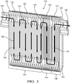
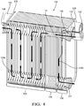
- the Unitary HPAC includes a hot-side heat exchanger assembly having a plurality of plates stacked and hermetically sealed between an upstream end plate and a downstream end plate.
- the plurality of stacked plates define a condenser/chiller portion adjacent the upstream end plate, a sub-cooler portion adjacent the downstream end plate, and a refrigerant receiver portion sandwiched between the condenser/chiller portion and the sub-cooler portion.
- the upstream end plate includes a refrigerant inlet and a hot coolant outlet
- the downstream end plate includes a refrigerant outlet, a hot coolant inlet, a sub-cooler coolant inlet and a sub-cooler coolant outlet.
- the unitary HPAC may further include an electrically driven compressor for circulating a refrigerant through the cold-side heat exchanger assembly and the hot-side heat exchanger assembly such that heat energy is transferred from the cold-side heat exchanger assembly to the hot-side heat exchanger assembly, an electrically driven hot side coolant pump in hydraulic communication with the coolant inlet of hot-side heat exchanger assembly, and an electrically driven cold side coolant pump in hydraulic communication with a coolant inlet of the cold-side heat exchanger assembly.
- an electrically driven compressor for circulating a refrigerant through the cold-side heat exchanger assembly and the hot-side heat exchanger assembly such that heat energy is transferred from the cold-side heat exchanger assembly to the hot-side heat exchanger assembly
- an electrically driven hot side coolant pump in hydraulic communication with the coolant inlet of hot-side heat exchanger assembly
- an electrically driven cold side coolant pump in hydraulic communication with a coolant inlet of the cold-side heat exchanger assembly.
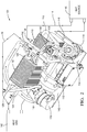
- An embodiment of the invention provides a Unitary HPAC that is compact and easily installed in virtually any compartment of a vehicle that is about the size a typical bread box.
- the Unitary HPAC scavenges heat from waste heat sources, such as the vehicle electronics, and use the waste heat to supplement the heating needs of the passenger compartment.
- the Unitary HPAC improves the driving ranges in cold climates by minimizing the use of electric current to power electric heaters and providing heat to the battery packs to maintain an optimal operating temperature.
- Unitary Heat Pump Air Conditioner (Unitary HPAC) System 10 and an embodiment of a Unitary HPAC 100 for use in a motor vehicle.
- the motor vehicle may be that of one with an internal combustion engine, a hybrid vehicle having both an internal combustion engine and an electric drive, or that of an electric vehicle having an electric drive.
- the Unitary HPAC System 10 includes a Unitary HPAC 100 that is compact and easily installed in virtually any compartment of the vehicle that is about the size of a bread box or larger. Further advantages of the Unitary HPAC System 10 will be readily appreciated by the reading of the disclosure below.
- the heat sink 42 may be a radiator type heat exchanger exposed to the outside ambient air where the waste heat is dissipated to the external environment.
- the flow paths of the cold and hot coolant loops 14, 16 throughout the vehicle may be reconfigured based on the cooling and heating needs of the vehicle.
- the cold and hot coolant loops 14, 16 may include a myriad of interconnecting branches with remotely activated valves at strategic nodes that may be reconfigured to redefine the flow paths of the cold and hot coolant loops 14, 16 to selectively provide cold or hot coolant flows to multiple designated heat sources 40 or heat sinks 42, respectively.
- the refrigerant cycle of the refrigerant loop 12 is typically the same as that of a dedicated air conditioning system of a motor vehicle operating in cooling mode.
- a two phase refrigerant is circulated through the refrigerant loop 12 by the compressor 24, which includes a suction side 36, also referred to as the low pressure side, and a discharge side 38, also referred to as the high pressure side.
- the suction side of the compressor receives a low pressure vapor phase refrigerant from the evaporator 22, after absorbing heat from the cold coolant loop 14 by way of the cold side chiller 30, and compresses it to a high pressure vapor phase refrigerant, which is then discharged to the condenser 18.
- the high pressure vapor phase refrigerant is condensed to a high pressure liquid phase refrigerant in the condenser 18, heat is transferred to the hot coolant loop16 by way of the hot side chiller 26.
- the high pressure liquid phase refrigerant passes through the refrigerant receiver 19 to separate any refrigerant vapor, the sub-cooler 21 to further cool the liquid phase refrigerant, and then to the refrigerant expansion device 20, through which the refrigerant begins to expand into a mixture of a bubbling gas-liquid phase.
- the bubbling gas-liquid phase refrigerant enters the evaporator 22 and continues to expand into the low pressure vapor refrigerant by absorbing heat from the cold coolant loop 14.
- the low pressure high quality/superheated vapor refrigerant is then cycled back to the suction side 36 of the compressor 24 to repeat the process.
- the flows of the hot refrigerant and hot coolants through the hot-side heat exchanger assembly 102 are in non-contact thermal communication; in other words, the hot coolants 48a, 48b and refrigerant are not intermingled, but are in thermal communication with each other. Heat energy from the higher temperature refrigerant is transferred to the lower temperature hot coolants 48a,48b, thereby increasing the temperature of the hot coolant 48 as it leaves the hot-side heat exchanger assembly 102 returning to the hot coolant loop 16.
- the vapor phase refrigerant remains within the top portion of the receiver portion 104, while the liquid phase refrigerant flows through the refrigerant passageway 122 within the sub-cooler portion 106 before exiting through the refrigerant outlet 132 to the TXV 108.
- the integral cold-side heat exchanger assembly 110 may also be plate-type heat exchangers.
- the integral cold-side heat exchanger assembly 110 includes a cold coolant inlet 138 and outlet 140, an evaporator refrigerant passageway for low pressure refrigerant flow, and a separate cold coolant passageway for cold coolant flow.
- the flows of the low pressure refrigerant and cold coolant through the integral cold-side heat exchanger assembly 110 are also in non-contact thermal communication with each other, and may be concurrent or countercurrent flow. Heat energy from the higher temperature cold coolant is transferred to the lower temperature evaporating refrigerant, thereby decreasing the temperature of the cold coolant as it leaves the integral cold-side heat exchanger assembly 110 and returning to the cold coolant loop 14.
Claims (11)
- Heißseitenwärmetauscheranordnung (102), die eine Vielzahl von Platten (120) aufweist, die zwischen einer stromaufwärtigen Endplatte (126) und einer stromabwärtigen Endplatte (128) gestapelt und hermetisch abgedichtet sind, definierend:einen Kondensator-/Kühlerabschnitt (103) angrenzend an die stromaufwärtige Endplatte (126), wobei die stromaufwärtige Endplatte (126) einen Kältemitteleinlass (130) und einen Auslass für heißes Kühlmittel (134) einschließt;einen Unterkühlerabschnitt (106) angrenzend an die stromabwärtige Endplatte (128), wobei die stromabwärtige Endplatte (128) einen Kältemittelauslass (132), einen Einlass für heißes Kühlmittel (136) und einen Unterkühler-Kühlmitteleinlass (135) aufweist;einen Kältemitteldurchgang (122) in hydraulischer Verbindung mit dem Kältemitteleinlass (130) und dem Kältemittelauslass (132), wobei sich der Kältemitteldurchgang (122) durch den Kondensator-/Kühlerabschnitt (103) und den Unterkühlerabschnitt (106) erstreckt;einen ersten Kühlmitteldurchgang (124a) in hydraulischer Verbindung mit dem Einlass für heißes Kühlmittel (136) und dem Auslass für heißes Kühlmittel (134), wobei sich der erste Kühlmitteldurchgang (124a) durch den Kondensator-/Kühlerabschnitt (103) erstreckt; undeinen zweiten Kühlmitteldurchgang (124b) in hydraulischer Verbindung mit dem Unterkühler-Kühlmitteleinlass (135) und einem Unterkühler-Kühlmittelauslass (137),wobei sich der zweite Kühlmitteldurchgang (124b) durch den Unterkühlerabschnitt (106) erstreckt;wobei der erste Kühlmitteldurchgang (124a) und der zweite Kühlmitteldurchgang (124b) in berührungsloser thermischer Verbindung mit dem Kältemitteldurchgang (122) stehen, dadurch gekennzeichnet, dassdie stromabwärtige Endplatte (128) auch den Unterkühler-Kühlmittelauslass (137) einschließt.
- Heißseitenwärmetauscheranordnung (102) nach Anspruch 1, weiter definierend einen Kältemittelsammlerabschnitt (104), der sandwichartig zwischen dem Kondensator-/Kühlerabschnitt (103) und dem Unterkühlerabschnitt (106) eingeschoben ist, wobei sich der Kältemitteldurchgang (122) durch den Kältemittelsammlerabschnitt (104) hindurch erstreckt.
- Heißseitenwärmetauscheranordnung (102) nach Anspruch 2, wobei sich der Kältemitteldurchgang (122) durch mindestens einen des Kondensator/Kühler-Abschnitts (103), des Sammlerabschnitts (104) und des Unterkühlerabschnitts (106) schlängelt.
- Heißseitenwärmetauscheranordnung (102) nach Anspruch 3, wobei der Kältemitteldurchgang (122) vom Kondensator-/Kühlerabschnitt (103) in den oberen Teil des Sammlerabschnitts (104) eintritt und aus dem unteren Teil des Sammlerabschnitts (104) zum Unterkühlerabschnitt (106) austritt.
- Heißseitenwärmetauscheranordnung (102) nach Anspruch 2, wobei die Mehrzahl von gestapelten Platten (120) der Heißseitenwärmetauscheranordnung (102) weiter einen ersten Kühlmittelsammler (131) definiert, der sich linear sowohl durch den Sammlerabschnitt (104) als auch durch den Unterkühlerabschnitt (106) erstreckt und in hydraulischer Verbindung mit dem ersten Kühlmitteldurchgang (124a) steht, der sich durch den Kondensator-/Kühlerabschnitt (103) und den Einlass (136) für heißes Kühlmittel erstreckt.
- Heißseitenwärmetauscheranordnung (102) nach Anspruch 5, wobei sich der erste Durchgang für heißes Kühlmittel (124a) durch den Kondensator-/Kühlerabschnitt (103) schlängelt.
- Heißseitenwärmetauscheranordnung (102) nach Anspruch 5, wobei sich der zweite Durchgang für heißes Kühlmittel (124b) durch den Unterkühlerabschnitt (106) schlängelt.
- Heißseitenwärmetauscheranordnung (102) nach Anspruch 5, wobei der erste Durchgang für heißes Kühlmittel (124a) im berührungslosen Gegenstrom mit dem Kältemitteldurchgang (122) ist.
- Heißseitenwärmetauscheranordnung (102) nach Anspruch 3, weiter umfassend:eine Kaltseitenwärmetauscheranordnung (110), die einen Kältemitteleinlass in hydraulischer Verbindung mit dem Kältemittelauslass (132) der Heißseitenwärmetauscheranordnung (102) und einem Kältemittelauslass in hydraulischer Verbindung mit dem Kältemitteleinlass (130) der Heißseitenwärmetauscheranordnung (102) aufweist; undeinen elektrisch angetriebenen Kompressor (112) zum Zirkulieren eines Kältemittels durch die Kaltseitenwärmetauscheranordnung (110) und die Heißseitenwärmetauscheranordnung (102), so dass Wärmeenergie von der Kaltseitenwärmetauscheranordnung (110) auf die Heißseitenwärmetauscheranordnung (102) übertragen wird.
- Heißseitenwärmetauscheranordnung (102) nach Anspruch 9, weiter umfassend eine elektrisch angetriebene Heißseitenkühlmittelpumpe (116) in hydraulischer Verbindung mit dem Kühlmitteleinlass der Heißseitenwärmetauscheranordnung (102) und eine elektrisch angetriebene Kaltseitenkühlmittelpumpe (32) in hydraulischer Verbindung mit einem Kühlmitteleinlass der Kaltseitenwärmetauscheranordnung (110).
- Einteiliges Wärmepumpen-Klimaanlage (100), die eine Heißseitenwärmetauscheranordnung (102) gemäß einem der vorstehenden Ansprüche umfasst.
Applications Claiming Priority (2)
| Application Number | Priority Date | Filing Date | Title |
|---|---|---|---|
| US13/396,211 US8899062B2 (en) | 2011-02-17 | 2012-02-14 | Plate-type heat pump air conditioner heat exchanger for a unitary heat pump air conditioner |
| US13/451,841 US9239193B2 (en) | 2011-02-17 | 2012-04-20 | Unitary heat pump air conditioner having a heat exchanger with an integral receiver and sub-cooler |
Publications (3)
| Publication Number | Publication Date |
|---|---|
| EP2629040A2 EP2629040A2 (de) | 2013-08-21 |
| EP2629040A3 EP2629040A3 (de) | 2018-04-11 |
| EP2629040B1 true EP2629040B1 (de) | 2020-07-29 |
Family
ID=47709917
Family Applications (1)
| Application Number | Title | Priority Date | Filing Date |
|---|---|---|---|
| EP13153583.3A Active EP2629040B1 (de) | 2012-02-14 | 2013-02-01 | Wärmepumpenklimaanlage mit Wärmetauscher mit integriertem Sammler und Unterkühler |
Country Status (2)
| Country | Link |
|---|---|
| EP (1) | EP2629040B1 (de) |
| CN (2) | CN203432005U (de) |
Families Citing this family (14)
| Publication number | Priority date | Publication date | Assignee | Title |
|---|---|---|---|---|
| EP2629040B1 (de) * | 2012-02-14 | 2020-07-29 | MAHLE International GmbH | Wärmepumpenklimaanlage mit Wärmetauscher mit integriertem Sammler und Unterkühler |
| JP6315191B2 (ja) * | 2014-04-25 | 2018-04-25 | パナソニックIpマネジメント株式会社 | 熱交換器 |
| DE102014113526A1 (de) | 2014-09-19 | 2016-03-24 | Halla Visteon Climate Control Corporation | Klimatisierungssystem für ein Kraftfahrzeug |
| DE102015103681A1 (de) | 2015-03-13 | 2016-09-15 | Halla Visteon Climate Control Corporation | Klimatisierungssystem eines Kraftfahrzeugs und Verfahren zum Betreiben des Klimatisierungssystems |
| DE102017109311B4 (de) | 2017-05-02 | 2022-04-21 | Hanon Systems | Vorrichtung für ein Klimatisierungssystem eines Kraftfahrzeugs sowie Verfahren zum Betreiben der Vorrichtung |
| KR102406126B1 (ko) * | 2017-08-09 | 2022-06-07 | 현대자동차 주식회사 | 차량용 ce 모듈 |
| DE102018129988A1 (de) | 2018-07-09 | 2020-01-09 | Hanon Systems | Kompaktwärmeübertragereinheit und Klimaanlagenmodul, insbesondere für Elektrofahrzeuge |
| FR3096764A1 (fr) * | 2019-05-27 | 2020-12-04 | Valeo Systemes Thermiques | Bouteille pour condenseur a eau de vehicule automobile |
| CN111006417A (zh) * | 2020-01-06 | 2020-04-14 | 林泳鑫 | 一种新能源汽车水冷式冷凝器 |
| FR3111971B1 (fr) * | 2020-06-29 | 2022-08-05 | Valeo Systemes Thermiques | Echangeur thermique pour véhicule automobile |
| FR3111975A1 (fr) * | 2020-06-30 | 2021-12-31 | Valeo Systemes Thermiques | Echangeur de chaleur monobloc comprenant au moins deux blocs d’échange de chaleur |
| EP4144549A1 (de) * | 2021-09-03 | 2023-03-08 | Valeo Klimasysteme GmbH | Heiz- und/oder kühlbehandlungsmodul für ein fahrzeug |
| DE102022200696A1 (de) | 2022-01-21 | 2023-07-27 | Mahle International Gmbh | System für ein Kraftfahrzeug |
| FR3134620A1 (fr) * | 2022-04-15 | 2023-10-20 | Valeo Systemes Thermiques | Echangeur de chaleur interne à plaques. |
Citations (1)
| Publication number | Priority date | Publication date | Assignee | Title |
|---|---|---|---|---|
| WO2011039186A1 (fr) * | 2009-09-30 | 2011-04-07 | Valeo Systemes Thermiques | Condenseur pour vehicule automobile a integration amelioree |
Family Cites Families (9)
| Publication number | Priority date | Publication date | Assignee | Title |
|---|---|---|---|---|
| EP0769666B1 (de) * | 1995-10-18 | 2003-03-12 | Calsonic Kansei Corporation | Verflüssiger mit einem Flüssigkeitsbehälter |
| US5704229A (en) * | 1996-12-18 | 1998-01-06 | The Boc Group, Inc. | Process and apparatus for producing nitrogen |
| KR100264815B1 (ko) * | 1997-06-16 | 2000-09-01 | 신영주 | 다단기액분리형응축기 |
| US7063137B2 (en) * | 2003-07-15 | 2006-06-20 | Delphi Technologies, Inc. | Heat pump with secondary loop air-conditioning system |
| FR2861166B1 (fr) * | 2003-10-21 | 2006-11-24 | Valeo Climatisation | Echangeur de chaleur utilisant un fluide d'accumulation |
| EP1616610B1 (de) * | 2004-07-13 | 2012-07-25 | Byeong-Seung Lee | Plattenwärmetauscher mit Kondensatabführung und Verfahren zur seiner Herstellung |
| SE534348C2 (sv) * | 2008-10-07 | 2011-07-19 | Scania Cv Abp | System och anordning innefattande en sammanbyggd kondensor och förångare |
| JP5427563B2 (ja) * | 2009-11-20 | 2014-02-26 | 三菱重工業株式会社 | インバータターボ冷凍機の性能評価装置 |
| EP2629040B1 (de) * | 2012-02-14 | 2020-07-29 | MAHLE International GmbH | Wärmepumpenklimaanlage mit Wärmetauscher mit integriertem Sammler und Unterkühler |
-
2013
- 2013-02-01 EP EP13153583.3A patent/EP2629040B1/de active Active
- 2013-02-07 CN CN201320071913.3U patent/CN203432005U/zh not_active Withdrawn - After Issue
- 2013-02-07 CN CN201310050004.6A patent/CN103245016B/zh active Active
Patent Citations (1)
| Publication number | Priority date | Publication date | Assignee | Title |
|---|---|---|---|---|
| WO2011039186A1 (fr) * | 2009-09-30 | 2011-04-07 | Valeo Systemes Thermiques | Condenseur pour vehicule automobile a integration amelioree |
Also Published As
| Publication number | Publication date |
|---|---|
| EP2629040A2 (de) | 2013-08-21 |
| CN103245016A (zh) | 2013-08-14 |
| CN103245016B (zh) | 2017-09-05 |
| CN203432005U (zh) | 2014-02-12 |
| EP2629040A3 (de) | 2018-04-11 |
Similar Documents
| Publication | Publication Date | Title |
|---|---|---|
| US9239193B2 (en) | Unitary heat pump air conditioner having a heat exchanger with an integral receiver and sub-cooler | |
| EP2629040B1 (de) | Wärmepumpenklimaanlage mit Wärmetauscher mit integriertem Sammler und Unterkühler | |
| US9494350B2 (en) | Plate-type heat pump air conditioner heat exchanger for a unitary heat pump air conditioner | |
| US9109840B2 (en) | Unitary heat pump air conditioner having a heat exchanger with an integral accumulator | |
| EP2629032B1 (de) | Einheitliche Wärmepumpenklimaanlage mit Wärmetauscher mit integriertem Akkumulator | |
| US9879891B2 (en) | Unitary heat pump air conditioner having a compressed vapor diversion loop | |
| US6789613B1 (en) | Double heat exchanger for vehicle air conditioner | |
| US9925845B2 (en) | Heat exchange system | |
| EP2972019B1 (de) | Einheitliche klimaanlage für eine wärmepumpe mit komprimierter dampfdiversifizierungsschleife | |
| US20140060102A1 (en) | Mild ambient vehicular heat pump system | |
| US8938989B2 (en) | Heat exchanger | |
| CN107914538B (zh) | 一种电动汽车热管理系统 | |
| JP2006216303A (ja) | 発熱機器の冷却構造 | |
| US20200130456A1 (en) | Cooling module for vehicle | |
| US20220134845A1 (en) | Heat exchanger and vehicle air conditioning system | |
| CN107709898B (zh) | 热交换器以及热泵系统 | |
| US10240826B2 (en) | Heat exchanger |
Legal Events
| Date | Code | Title | Description |
|---|---|---|---|
| PUAI | Public reference made under article 153(3) epc to a published international application that has entered the european phase |
Free format text: ORIGINAL CODE: 0009012 |
|
| AK | Designated contracting states |
Kind code of ref document: A2 Designated state(s): AL AT BE BG CH CY CZ DE DK EE ES FI FR GB GR HR HU IE IS IT LI LT LU LV MC MK MT NL NO PL PT RO RS SE SI SK SM TR |
|
| AX | Request for extension of the european patent |
Extension state: BA ME |
|
| RAP1 | Party data changed (applicant data changed or rights of an application transferred) |
Owner name: MAHLE INTERNATIONAL GMBH |
|
| PUAL | Search report despatched |
Free format text: ORIGINAL CODE: 0009013 |
|
| AK | Designated contracting states |
Kind code of ref document: A3 Designated state(s): AL AT BE BG CH CY CZ DE DK EE ES FI FR GB GR HR HU IE IS IT LI LT LU LV MC MK MT NL NO PL PT RO RS SE SI SK SM TR |
|
| AX | Request for extension of the european patent |
Extension state: BA ME |
|
| RIC1 | Information provided on ipc code assigned before grant |
Ipc: F28D 9/00 20060101ALI20180307BHEP Ipc: B60H 1/00 20060101ALI20180307BHEP Ipc: F28F 3/08 20060101ALI20180307BHEP Ipc: F25B 29/00 20060101AFI20180307BHEP |
|
| STAA | Information on the status of an ep patent application or granted ep patent |
Free format text: STATUS: REQUEST FOR EXAMINATION WAS MADE |
|
| 17P | Request for examination filed |
Effective date: 20181010 |
|
| RBV | Designated contracting states (corrected) |
Designated state(s): AL AT BE BG CH CY CZ DE DK EE ES FI FR GB GR HR HU IE IS IT LI LT LU LV MC MK MT NL NO PL PT RO RS SE SI SK SM TR |
|
| STAA | Information on the status of an ep patent application or granted ep patent |
Free format text: STATUS: EXAMINATION IS IN PROGRESS |
|
| 17Q | First examination report despatched |
Effective date: 20190604 |
|
| REG | Reference to a national code |
Ref country code: DE Ref legal event code: R079 Ref document number: 602013071054 Country of ref document: DE Free format text: PREVIOUS MAIN CLASS: F28D0009000000 Ipc: F25B0029000000 |
|
| GRAP | Despatch of communication of intention to grant a patent |
Free format text: ORIGINAL CODE: EPIDOSNIGR1 |
|
| STAA | Information on the status of an ep patent application or granted ep patent |
Free format text: STATUS: GRANT OF PATENT IS INTENDED |
|
| RIC1 | Information provided on ipc code assigned before grant |
Ipc: F28D 21/00 20060101ALI20200305BHEP Ipc: F25B 29/00 20060101AFI20200305BHEP Ipc: F25B 25/00 20060101ALI20200305BHEP Ipc: F28F 3/08 20060101ALI20200305BHEP Ipc: B60H 1/00 20060101ALI20200305BHEP Ipc: F25B 40/02 20060101ALI20200305BHEP Ipc: F25B 39/04 20060101ALI20200305BHEP Ipc: B60H 1/32 20060101ALI20200305BHEP Ipc: F24F 13/30 20060101ALI20200305BHEP Ipc: F28D 9/00 20060101ALI20200305BHEP |
|
| INTG | Intention to grant announced |
Effective date: 20200403 |
|
| INTG | Intention to grant announced |
Effective date: 20200403 |
|
| GRAS | Grant fee paid |
Free format text: ORIGINAL CODE: EPIDOSNIGR3 |
|
| GRAA | (expected) grant |
Free format text: ORIGINAL CODE: 0009210 |
|
| STAA | Information on the status of an ep patent application or granted ep patent |
Free format text: STATUS: THE PATENT HAS BEEN GRANTED |
|
| AK | Designated contracting states |
Kind code of ref document: B1 Designated state(s): AL AT BE BG CH CY CZ DE DK EE ES FI FR GB GR HR HU IE IS IT LI LT LU LV MC MK MT NL NO PL PT RO RS SE SI SK SM TR |
|
| REG | Reference to a national code |
Ref country code: GB Ref legal event code: FG4D |
|
| REG | Reference to a national code |
Ref country code: CH Ref legal event code: EP |
|
| REG | Reference to a national code |
Ref country code: AT Ref legal event code: REF Ref document number: 1296266 Country of ref document: AT Kind code of ref document: T Effective date: 20200815 |
|
| REG | Reference to a national code |
Ref country code: IE Ref legal event code: FG4D |
|
| REG | Reference to a national code |
Ref country code: DE Ref legal event code: R096 Ref document number: 602013071054 Country of ref document: DE |
|
| REG | Reference to a national code |
Ref country code: LT Ref legal event code: MG4D |
|
| REG | Reference to a national code |
Ref country code: NL Ref legal event code: MP Effective date: 20200729 |
|
| REG | Reference to a national code |
Ref country code: AT Ref legal event code: MK05 Ref document number: 1296266 Country of ref document: AT Kind code of ref document: T Effective date: 20200729 |
|
| PG25 | Lapsed in a contracting state [announced via postgrant information from national office to epo] |
Ref country code: SE Free format text: LAPSE BECAUSE OF FAILURE TO SUBMIT A TRANSLATION OF THE DESCRIPTION OR TO PAY THE FEE WITHIN THE PRESCRIBED TIME-LIMIT Effective date: 20200729 Ref country code: PT Free format text: LAPSE BECAUSE OF FAILURE TO SUBMIT A TRANSLATION OF THE DESCRIPTION OR TO PAY THE FEE WITHIN THE PRESCRIBED TIME-LIMIT Effective date: 20201130 Ref country code: FI Free format text: LAPSE BECAUSE OF FAILURE TO SUBMIT A TRANSLATION OF THE DESCRIPTION OR TO PAY THE FEE WITHIN THE PRESCRIBED TIME-LIMIT Effective date: 20200729 Ref country code: BG Free format text: LAPSE BECAUSE OF FAILURE TO SUBMIT A TRANSLATION OF THE DESCRIPTION OR TO PAY THE FEE WITHIN THE PRESCRIBED TIME-LIMIT Effective date: 20201029 Ref country code: ES Free format text: LAPSE BECAUSE OF FAILURE TO SUBMIT A TRANSLATION OF THE DESCRIPTION OR TO PAY THE FEE WITHIN THE PRESCRIBED TIME-LIMIT Effective date: 20200729 Ref country code: GR Free format text: LAPSE BECAUSE OF FAILURE TO SUBMIT A TRANSLATION OF THE DESCRIPTION OR TO PAY THE FEE WITHIN THE PRESCRIBED TIME-LIMIT Effective date: 20201030 Ref country code: LT Free format text: LAPSE BECAUSE OF FAILURE TO SUBMIT A TRANSLATION OF THE DESCRIPTION OR TO PAY THE FEE WITHIN THE PRESCRIBED TIME-LIMIT Effective date: 20200729 Ref country code: NO Free format text: LAPSE BECAUSE OF FAILURE TO SUBMIT A TRANSLATION OF THE DESCRIPTION OR TO PAY THE FEE WITHIN THE PRESCRIBED TIME-LIMIT Effective date: 20201029 Ref country code: AT Free format text: LAPSE BECAUSE OF FAILURE TO SUBMIT A TRANSLATION OF THE DESCRIPTION OR TO PAY THE FEE WITHIN THE PRESCRIBED TIME-LIMIT Effective date: 20200729 Ref country code: HR Free format text: LAPSE BECAUSE OF FAILURE TO SUBMIT A TRANSLATION OF THE DESCRIPTION OR TO PAY THE FEE WITHIN THE PRESCRIBED TIME-LIMIT Effective date: 20200729 |
|
| PG25 | Lapsed in a contracting state [announced via postgrant information from national office to epo] |
Ref country code: IS Free format text: LAPSE BECAUSE OF FAILURE TO SUBMIT A TRANSLATION OF THE DESCRIPTION OR TO PAY THE FEE WITHIN THE PRESCRIBED TIME-LIMIT Effective date: 20201129 Ref country code: PL Free format text: LAPSE BECAUSE OF FAILURE TO SUBMIT A TRANSLATION OF THE DESCRIPTION OR TO PAY THE FEE WITHIN THE PRESCRIBED TIME-LIMIT Effective date: 20200729 Ref country code: RS Free format text: LAPSE BECAUSE OF FAILURE TO SUBMIT A TRANSLATION OF THE DESCRIPTION OR TO PAY THE FEE WITHIN THE PRESCRIBED TIME-LIMIT Effective date: 20200729 Ref country code: LV Free format text: LAPSE BECAUSE OF FAILURE TO SUBMIT A TRANSLATION OF THE DESCRIPTION OR TO PAY THE FEE WITHIN THE PRESCRIBED TIME-LIMIT Effective date: 20200729 |
|
| PG25 | Lapsed in a contracting state [announced via postgrant information from national office to epo] |
Ref country code: NL Free format text: LAPSE BECAUSE OF FAILURE TO SUBMIT A TRANSLATION OF THE DESCRIPTION OR TO PAY THE FEE WITHIN THE PRESCRIBED TIME-LIMIT Effective date: 20200729 |
|
| PG25 | Lapsed in a contracting state [announced via postgrant information from national office to epo] |
Ref country code: EE Free format text: LAPSE BECAUSE OF FAILURE TO SUBMIT A TRANSLATION OF THE DESCRIPTION OR TO PAY THE FEE WITHIN THE PRESCRIBED TIME-LIMIT Effective date: 20200729 Ref country code: CZ Free format text: LAPSE BECAUSE OF FAILURE TO SUBMIT A TRANSLATION OF THE DESCRIPTION OR TO PAY THE FEE WITHIN THE PRESCRIBED TIME-LIMIT Effective date: 20200729 Ref country code: DK Free format text: LAPSE BECAUSE OF FAILURE TO SUBMIT A TRANSLATION OF THE DESCRIPTION OR TO PAY THE FEE WITHIN THE PRESCRIBED TIME-LIMIT Effective date: 20200729 Ref country code: IT Free format text: LAPSE BECAUSE OF FAILURE TO SUBMIT A TRANSLATION OF THE DESCRIPTION OR TO PAY THE FEE WITHIN THE PRESCRIBED TIME-LIMIT Effective date: 20200729 Ref country code: SM Free format text: LAPSE BECAUSE OF FAILURE TO SUBMIT A TRANSLATION OF THE DESCRIPTION OR TO PAY THE FEE WITHIN THE PRESCRIBED TIME-LIMIT Effective date: 20200729 Ref country code: RO Free format text: LAPSE BECAUSE OF FAILURE TO SUBMIT A TRANSLATION OF THE DESCRIPTION OR TO PAY THE FEE WITHIN THE PRESCRIBED TIME-LIMIT Effective date: 20200729 |
|
| REG | Reference to a national code |
Ref country code: DE Ref legal event code: R097 Ref document number: 602013071054 Country of ref document: DE |
|
| PG25 | Lapsed in a contracting state [announced via postgrant information from national office to epo] |
Ref country code: AL Free format text: LAPSE BECAUSE OF FAILURE TO SUBMIT A TRANSLATION OF THE DESCRIPTION OR TO PAY THE FEE WITHIN THE PRESCRIBED TIME-LIMIT Effective date: 20200729 |
|
| PLBE | No opposition filed within time limit |
Free format text: ORIGINAL CODE: 0009261 |
|
| STAA | Information on the status of an ep patent application or granted ep patent |
Free format text: STATUS: NO OPPOSITION FILED WITHIN TIME LIMIT |
|
| PG25 | Lapsed in a contracting state [announced via postgrant information from national office to epo] |
Ref country code: SK Free format text: LAPSE BECAUSE OF FAILURE TO SUBMIT A TRANSLATION OF THE DESCRIPTION OR TO PAY THE FEE WITHIN THE PRESCRIBED TIME-LIMIT Effective date: 20200729 |
|
| 26N | No opposition filed |
Effective date: 20210430 |
|
| PG25 | Lapsed in a contracting state [announced via postgrant information from national office to epo] |
Ref country code: SI Free format text: LAPSE BECAUSE OF FAILURE TO SUBMIT A TRANSLATION OF THE DESCRIPTION OR TO PAY THE FEE WITHIN THE PRESCRIBED TIME-LIMIT Effective date: 20200729 |
|
| PG25 | Lapsed in a contracting state [announced via postgrant information from national office to epo] |
Ref country code: MC Free format text: LAPSE BECAUSE OF FAILURE TO SUBMIT A TRANSLATION OF THE DESCRIPTION OR TO PAY THE FEE WITHIN THE PRESCRIBED TIME-LIMIT Effective date: 20200729 |
|
| GBPC | Gb: european patent ceased through non-payment of renewal fee |
Effective date: 20210201 |
|
| REG | Reference to a national code |
Ref country code: BE Ref legal event code: MM Effective date: 20210228 |
|
| PG25 | Lapsed in a contracting state [announced via postgrant information from national office to epo] |
Ref country code: CH Free format text: LAPSE BECAUSE OF NON-PAYMENT OF DUE FEES Effective date: 20210228 Ref country code: LU Free format text: LAPSE BECAUSE OF NON-PAYMENT OF DUE FEES Effective date: 20210201 Ref country code: LI Free format text: LAPSE BECAUSE OF NON-PAYMENT OF DUE FEES Effective date: 20210228 |
|
| PG25 | Lapsed in a contracting state [announced via postgrant information from national office to epo] |
Ref country code: GB Free format text: LAPSE BECAUSE OF NON-PAYMENT OF DUE FEES Effective date: 20210201 Ref country code: IE Free format text: LAPSE BECAUSE OF NON-PAYMENT OF DUE FEES Effective date: 20210201 Ref country code: FR Free format text: LAPSE BECAUSE OF NON-PAYMENT OF DUE FEES Effective date: 20210228 |
|
| PG25 | Lapsed in a contracting state [announced via postgrant information from national office to epo] |
Ref country code: BE Free format text: LAPSE BECAUSE OF NON-PAYMENT OF DUE FEES Effective date: 20210228 |
|
| PG25 | Lapsed in a contracting state [announced via postgrant information from national office to epo] |
Ref country code: HU Free format text: LAPSE BECAUSE OF FAILURE TO SUBMIT A TRANSLATION OF THE DESCRIPTION OR TO PAY THE FEE WITHIN THE PRESCRIBED TIME-LIMIT; INVALID AB INITIO Effective date: 20130201 |
|
| PGFP | Annual fee paid to national office [announced via postgrant information from national office to epo] |
Ref country code: DE Payment date: 20230227 Year of fee payment: 11 |
|
| PG25 | Lapsed in a contracting state [announced via postgrant information from national office to epo] |
Ref country code: CY Free format text: LAPSE BECAUSE OF FAILURE TO SUBMIT A TRANSLATION OF THE DESCRIPTION OR TO PAY THE FEE WITHIN THE PRESCRIBED TIME-LIMIT Effective date: 20200729 |