EP2629012B1 - Pellet stove with system of self-cleaning of the brazier - Google Patents
Pellet stove with system of self-cleaning of the brazier Download PDFInfo
- Publication number
- EP2629012B1 EP2629012B1 EP13155544.3A EP13155544A EP2629012B1 EP 2629012 B1 EP2629012 B1 EP 2629012B1 EP 13155544 A EP13155544 A EP 13155544A EP 2629012 B1 EP2629012 B1 EP 2629012B1
- Authority
- EP
- European Patent Office
- Prior art keywords
- pipe
- brazier
- air
- stove
- pellet stove
- Prior art date
- Legal status (The legal status is an assumption and is not a legal conclusion. Google has not performed a legal analysis and makes no representation as to the accuracy of the status listed.)
- Not-in-force
Links
- 239000008188 pellet Substances 0.000 title claims description 25
- 238000004140 cleaning Methods 0.000 title claims description 14
- 238000002485 combustion reaction Methods 0.000 claims description 15
- 239000002956 ash Substances 0.000 claims description 9
- 235000002918 Fraxinus excelsior Nutrition 0.000 claims description 8
- UGFAIRIUMAVXCW-UHFFFAOYSA-N Carbon monoxide Chemical compound [O+]#[C-] UGFAIRIUMAVXCW-UHFFFAOYSA-N 0.000 claims description 6
- 239000003546 flue gas Substances 0.000 claims description 6
- 238000000605 extraction Methods 0.000 claims description 5
- 239000003570 air Substances 0.000 description 22
- 230000008030 elimination Effects 0.000 description 3
- 238000003379 elimination reaction Methods 0.000 description 3
- 238000004519 manufacturing process Methods 0.000 description 3
- CURLTUGMZLYLDI-UHFFFAOYSA-N Carbon dioxide Chemical compound O=C=O CURLTUGMZLYLDI-UHFFFAOYSA-N 0.000 description 2
- 239000012080 ambient air Substances 0.000 description 2
- 239000000428 dust Substances 0.000 description 2
- 239000000446 fuel Substances 0.000 description 2
- 229910002092 carbon dioxide Inorganic materials 0.000 description 1
- 239000001569 carbon dioxide Substances 0.000 description 1
- 230000001419 dependent effect Effects 0.000 description 1
- 239000007789 gas Substances 0.000 description 1
- 230000002045 lasting effect Effects 0.000 description 1
- 238000000034 method Methods 0.000 description 1
- 238000005192 partition Methods 0.000 description 1
Images


Classifications
-
- F—MECHANICAL ENGINEERING; LIGHTING; HEATING; WEAPONS; BLASTING
- F23—COMBUSTION APPARATUS; COMBUSTION PROCESSES
- F23B—METHODS OR APPARATUS FOR COMBUSTION USING ONLY SOLID FUEL
- F23B30/00—Combustion apparatus with driven means for agitating the burning fuel; Combustion apparatus with driven means for advancing the burning fuel through the combustion chamber
- F23B30/02—Combustion apparatus with driven means for agitating the burning fuel; Combustion apparatus with driven means for advancing the burning fuel through the combustion chamber with movable, e.g. vibratable, fuel-supporting surfaces; with fuel-supporting surfaces that have movable parts
-
- F—MECHANICAL ENGINEERING; LIGHTING; HEATING; WEAPONS; BLASTING
- F23—COMBUSTION APPARATUS; COMBUSTION PROCESSES
- F23H—GRATES; CLEANING OR RAKING GRATES
- F23H9/00—Revolving-grates; Rocking or shaking grates
- F23H9/02—Revolving cylindrical grates
-
- F—MECHANICAL ENGINEERING; LIGHTING; HEATING; WEAPONS; BLASTING
- F24—HEATING; RANGES; VENTILATING
- F24B—DOMESTIC STOVES OR RANGES FOR SOLID FUELS; IMPLEMENTS FOR USE IN CONNECTION WITH STOVES OR RANGES
- F24B1/00—Stoves or ranges
- F24B1/18—Stoves with open fires, e.g. fireplaces
- F24B1/185—Stoves with open fires, e.g. fireplaces with air-handling means, heat exchange means, or additional provisions for convection heating ; Controlling combustion
- F24B1/189—Stoves with open fires, e.g. fireplaces with air-handling means, heat exchange means, or additional provisions for convection heating ; Controlling combustion characterised by air-handling means, i.e. of combustion-air, heated-air, or flue-gases, e.g. draught control dampers
- F24B1/19—Supplying combustion-air
- F24B1/1902—Supplying combustion-air in combination with provisions for heating air only
-
- F—MECHANICAL ENGINEERING; LIGHTING; HEATING; WEAPONS; BLASTING
- F24—HEATING; RANGES; VENTILATING
- F24B—DOMESTIC STOVES OR RANGES FOR SOLID FUELS; IMPLEMENTS FOR USE IN CONNECTION WITH STOVES OR RANGES
- F24B1/00—Stoves or ranges
- F24B1/18—Stoves with open fires, e.g. fireplaces
- F24B1/191—Component parts; Accessories
- F24B1/1915—Means for removing ash
-
- F—MECHANICAL ENGINEERING; LIGHTING; HEATING; WEAPONS; BLASTING
- F24—HEATING; RANGES; VENTILATING
- F24B—DOMESTIC STOVES OR RANGES FOR SOLID FUELS; IMPLEMENTS FOR USE IN CONNECTION WITH STOVES OR RANGES
- F24B1/00—Stoves or ranges
- F24B1/18—Stoves with open fires, e.g. fireplaces
- F24B1/191—Component parts; Accessories
- F24B1/193—Grates; Irons
-
- F—MECHANICAL ENGINEERING; LIGHTING; HEATING; WEAPONS; BLASTING
- F24—HEATING; RANGES; VENTILATING
- F24H—FLUID HEATERS, e.g. WATER OR AIR HEATERS, HAVING HEAT-GENERATING MEANS, e.g. HEAT PUMPS, IN GENERAL
- F24H3/00—Air heaters
- F24H3/02—Air heaters with forced circulation
- F24H3/06—Air heaters with forced circulation the air being kept separate from the heating medium, e.g. using forced circulation of air over radiators
- F24H3/08—Air heaters with forced circulation the air being kept separate from the heating medium, e.g. using forced circulation of air over radiators by tubes
- F24H3/088—Air heaters with forced circulation the air being kept separate from the heating medium, e.g. using forced circulation of air over radiators by tubes using solid fuel
Definitions
- the object of the invention is a pellet stove provided with a system for self-cleaning of the brazier and of feeding of combustion air to the same.
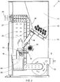
- a pellet stove of the prior art illustrated in the accompanying Figure 1 , comprises a case 10, with a substantially parallelepiped shape, in whose upper part a hopper 11 is placed wherein the pellet 12 is loaded, which by means of a worm conveyor 13 is conducted to a drop pipe 14 which feeds it to a brazier 15 where combustion takes place.
- the brazier 15 is mounted on a support 16, and has holes 17 for the passage of the combustion air which is aspirated from the outside by the pressure drop created by a flue gas extraction fan 18, as illustrated by the arrows. More particularly the fresh air from the environment indicated by the arrows with reference numeral 19, entering through an opening 20 and a conduit 21, is drawn into the brazier 15 through the holes 17, while the hot combusted gases, denoted by the arrows with reference numeral 22, are aspirated and expelled by the fan 18.
- a further fan 25 feeds ambient air represented by the arrows denoted by reference numeral 26, which heats by passing through an exchanger 27 where it takes heat from the hot flue gas produced by the combustion and is fed back hot into the environment, as represented by the arrows 28.
- a box 29 is placed for the collection of the ashes 30.
- the cleaning of the brazier takes place periodically by increasing the speed of rotation of the flue gas extraction fan 18, in such a way as to increase the pressure drop and therefore make the ashes jump upwards and then make them fall into the underlying collection box 29, as schematically shown by the dots in Figure 1 .
- Figure 1 also shows schematically a resistor, referred to in jargon as plug, which generates the heat necessary for igniting the pellets in the brazier 15.
- a constructionally complex burner apparatus or device which, in one embodiment, comprises a brazier below which a component is placed which can rotate with respect to a horizontal rotation axis suitable for collecting and holding the combustion products in order to convey them, by means of a rotation, in the direction of an underlying ashes collection box, with said brazier which comprises, moreover, elements of retaining of the ash provided with springs and hinged on the base of the brazier at the rotatable component and a fuel retaining slide placed above the openable base of the brazier and of the rotatable component and such as to be able to be moved inside and outside of the brazier in order to retain the burning fuel or allow the drop thereof in the direction of the rotatable component.
- the object of the invention is that of eliminating the aforementioned disadvantages of the prior art.
- More particularly one object of the invention is that of providing a system of self-cleaning of the brazier of a pellet stove which allows a perfect disincrustation of the holes of feeding of the combustion air.
- Another object of the present invention is that of providing such a self-cleaning system which allows at the same time the feeding of the combustion air into the brazier.
- Yet another object of the invention is that of providing such a system which is simple and economical to manufacture.
- the pellet stove according to the invention has, on the base of the brazier, a pipe mounted between the walls of the case of the stove so as to be able to rotate around its axis and having at least one end, preferably both ends, open for the entry of ambient air, and a plurality of holes at its section placed at the brazier.
- This perforated pipe constitutes in practice the base wall of the brazier and has its shell a short distance from two opposite longitudinal walls placed as a funnel of the brazier.
- the aforementioned perforated pipe acts both as feed of the comburent air to the brazier and as cleaner element for the elimination of the ashes and the removal of possible incrustations.
- the ashes and possible incrustations which may have formed around the holes of entry of the air are evacuated through the gap between the shell of the pipe and one of said longitudinal walls of the brazier.
- the pipe preferably has at least one longitudinal baffle, preferably at least two, in such a way as to divide its span into several longitudinal sectors and block the openings of entry of the air in the lower half, in such a way as to limit to a minimum the possible escape of air through holes of the pipe not placed inside the brazier, for whatever angular position of the same pipe.
- the pipe being totally inside the stove body, it allows a preheating of the air, and therefore a better yield of the combustion.
- a pipe 50 is positioned, supported in such a way as to be able to rotate around its axis from the sides 51 of the case 10 of the stove, by means of bushings or bearings 52, in order to reduce the friction during the rotation to a minimum.
- the pipe 50 can be made to rotate by means of a motor, not shown, which controls a chain 53 meshing a pinion 54 mounted at one end of the pipe. Both ends of the pipe 50 are open to allow the entry of air from the environment as indicated by the arrows 19.
- baffles are preferably placed in the pipe 50, in the example shown four baffles 56 placed in a cross in order to channel the flow of air 19. Naturally the number of baffles can be higher or lower than four.
- Respective fixed shutters 57 are placed at the ends 55 of the pipe 50 (see also Fig. 5 ) which, together with the baffles or partitions 56 inside the pipe, allow the air to be conveyed only in the upper zone of the pipe.
- the pipe 50 is placed in such a way as to constitute in practice the base wall of the brazier 15, and therefore constitute an integral part of the same.
- the brazier or crate 15 for containing the pellets has a substantially overturned truncated pyramid shape, with two opposite walls 60 which extend longitudinally along the axis of the pipe 50 and converge as a funnel on the shell of the pipe, leaving a small gap 61 between their ends and the shell of the pipe 50.
- the section of the pipe 50 below the brazier 15 has a plurality of holes 62 on the entire section, to allow the entry of air in the brazier 15.
- the pipe 50 feeds the combustion air to the pellet 12 in the brazier 15, air which is aspirated through the holes 62 by the pressure drop created by the flue gas extraction fan 18. Since the pipe 50 constitutes an integral part of the brazier 15, and is therefore at high temperature at least in the zone of the support 16 of the brazier, the air 19 undergoes a preheating before coming into contact with the pellets 12 in the brazier 15, thus improving the heat yield of the stove and reducing the production of carbon dioxide.
- the pipe 50 When it is necessary to perform the cleaning, the pipe 50 is rotated, as indicated by the arrow in Fig. 3 , thus making the ashes 30 fall into the collection box 29, through the gap 61 between a wall 60 of the brazier and the shell of the pipe 50.
- a control unit (not shown) is provided, with a user interface through which it is possible to set the cyclical cleaning times, on the basis of the thermal power of the stove, for example a slow rotation of the pipe 50 (1-10 rpm) lasting 10-60 seconds every 3-8 minutes can be provided. When the stove is extinguished a longer rotation is provided, for example of 3-12 minutes.
Description
- The object of the invention is a pellet stove provided with a system for self-cleaning of the brazier and of feeding of combustion air to the same.
- A pellet stove of the prior art, illustrated in the accompanying
Figure 1 , comprises acase 10, with a substantially parallelepiped shape, in whose upper part ahopper 11 is placed wherein thepellet 12 is loaded, which by means of aworm conveyor 13 is conducted to adrop pipe 14 which feeds it to abrazier 15 where combustion takes place. - The
brazier 15 is mounted on asupport 16, and hasholes 17 for the passage of the combustion air which is aspirated from the outside by the pressure drop created by a fluegas extraction fan 18, as illustrated by the arrows. More particularly the fresh air from the environment indicated by the arrows withreference numeral 19, entering through anopening 20 and aconduit 21, is drawn into thebrazier 15 through theholes 17, while the hot combusted gases, denoted by the arrows withreference numeral 22, are aspirated and expelled by thefan 18. - A
further fan 25 feeds ambient air represented by the arrows denoted byreference numeral 26, which heats by passing through anexchanger 27 where it takes heat from the hot flue gas produced by the combustion and is fed back hot into the environment, as represented by thearrows 28. - Below the brazier 15 a
box 29 is placed for the collection of theashes 30.
According to this known technique the cleaning of the brazier takes place periodically by increasing the speed of rotation of the fluegas extraction fan 18, in such a way as to increase the pressure drop and therefore make the ashes jump upwards and then make them fall into theunderlying collection box 29, as schematically shown by the dots inFigure 1 . -
Figure 1 also shows schematically a resistor, referred to in jargon as plug, which generates the heat necessary for igniting the pellets in thebrazier 15. - The system of cleaning of the
brazier 15 described above has proved to be inadequate in eliminating possible incrustations which may form on the walls of thebrazier 15, which tend to obstruct theholes 17 of passage of the combustion air, with consequent loss of efficiency of the stove. Therefore frequent manual cleanings of thebrazier 15 are made necessary. - Alternative systems for the removal of the ashes have likewise been proposed, such as for example a screw placed on the base of the brazier, having half right threading and half left threading which, when it is rotated, draws the dust from the brazier, making it drop into the collection box below.
- Such a solution is somewhat complex and does not allow optimal cleaning to be carried out, in particular possible incrustations to be eliminated which may have formed at the holes of feeding of the combustion air into the brazier.
- A further solution is described in the document
US2007/0215021 wherein a constructionally complex burner apparatus or device is illustrated which, in one embodiment, comprises a brazier below which a component is placed which can rotate with respect to a horizontal rotation axis suitable for collecting and holding the combustion products in order to convey them, by means of a rotation, in the direction of an underlying ashes collection box, with said brazier which comprises, moreover, elements of retaining of the ash provided with springs and hinged on the base of the brazier at the rotatable component and a fuel retaining slide placed above the openable base of the brazier and of the rotatable component and such as to be able to be moved inside and outside of the brazier in order to retain the burning fuel or allow the drop thereof in the direction of the rotatable component. - However, this solution too has some major disadvantages linked to the constructional complexity and to the fact that it does not allow the transfer to the pellets of air coming from the outside in such a way as to improve the heat yield of the burner device.
- The object of the invention is that of eliminating the aforementioned disadvantages of the prior art.
- More particularly one object of the invention is that of providing a system of self-cleaning of the brazier of a pellet stove which allows a perfect disincrustation of the holes of feeding of the combustion air.
- Another object of the present invention is that of providing such a self-cleaning system which allows at the same time the feeding of the combustion air into the brazier.
- Yet another object of the invention is that of providing such a system which is simple and economical to manufacture.
- These objects are achieved in accordance with the features of the annexed
independent claim 1. - Advantageous embodiments of the invention are disclosed by the dependent claims. Substantially the pellet stove according to the invention, of the type described previously, has, on the base of the brazier, a pipe mounted between the walls of the case of the stove so as to be able to rotate around its axis and having at least one end, preferably both ends, open for the entry of ambient air, and a plurality of holes at its section placed at the brazier.
- This perforated pipe constitutes in practice the base wall of the brazier and has its shell a short distance from two opposite longitudinal walls placed as a funnel of the brazier.
- In this way the aforementioned perforated pipe acts both as feed of the comburent air to the brazier and as cleaner element for the elimination of the ashes and the removal of possible incrustations. In fact, by periodically rotating this pipe, the ashes and possible incrustations which may have formed around the holes of entry of the air are evacuated through the gap between the shell of the pipe and one of said longitudinal walls of the brazier.
- The pipe preferably has at least one longitudinal baffle, preferably at least two, in such a way as to divide its span into several longitudinal sectors and block the openings of entry of the air in the lower half, in such a way as to limit to a minimum the possible escape of air through holes of the pipe not placed inside the brazier, for whatever angular position of the same pipe.
- The pipe being totally inside the stove body, it allows a preheating of the air, and therefore a better yield of the combustion.
- Other advantages obtained with the system according to the invention are reduced cleaning operations, the elimination of the failed lightings and of the incorrect combustions due to the clogging of the holes of passage of the air and the simplicity of manufacture of the single components.
- Further features of the invention will be made clearer by the following detailed description, referred to one of its embodiments purely by way of a non-limiting example illustrated in the accompanying drawings, wherein:
-
Fig. 1 is a schematic sectioned view of a traditional pellet stove, as described previously; -
Fig. 2 is a view like that ofFig. 1 of a pellet stove incorporating the self-cleaning system according to the invention; -
Fig. 3 is an enlargement of a detail ofFig. 2 relating to the brazier and to the box of collection of the dust; -
Fig. 4 is a section taken along the plane IV-IV ofFig. 3 ; -
Fig. 5 is a further enlarged schematic view, partially sectioned, partially viewed along the arrow F ofFigure 4 . - A traditional pellet stove shown in
Fig. 1 has been described previously. - Herein below the pellet stove according to the invention will be described with reference to
Figs. 2 to 5 , wherein the same reference numerals are given ofFig. 1 to denote identical or similar parts, which will not be described further, as likewise the functioning of the stove will not be repeated, also already described in brief. - The description will therefore be limited to the innovative parts of the stove according to the invention.
- As shown more clearly in
Figs. 3 and 4 , on the base of the brazier 15 apipe 50 is positioned, supported in such a way as to be able to rotate around its axis from thesides 51 of thecase 10 of the stove, by means of bushings orbearings 52, in order to reduce the friction during the rotation to a minimum. - The
pipe 50 can be made to rotate by means of a motor, not shown, which controls achain 53 meshing apinion 54 mounted at one end of the pipe. Both ends of thepipe 50 are open to allow the entry of air from the environment as indicated by thearrows 19. - Longitudinal baffles are preferably placed in the
pipe 50, in the example shown fourbaffles 56 placed in a cross in order to channel the flow ofair 19. Naturally the number of baffles can be higher or lower than four. - Respective
fixed shutters 57 are placed at theends 55 of the pipe 50 (see alsoFig. 5 ) which, together with the baffles orpartitions 56 inside the pipe, allow the air to be conveyed only in the upper zone of the pipe. - The
pipe 50 is placed in such a way as to constitute in practice the base wall of thebrazier 15, and therefore constitute an integral part of the same. - In the example shown the brazier or
crate 15 for containing the pellets has a substantially overturned truncated pyramid shape, with twoopposite walls 60 which extend longitudinally along the axis of thepipe 50 and converge as a funnel on the shell of the pipe, leaving asmall gap 61 between their ends and the shell of thepipe 50. - The section of the
pipe 50 below thebrazier 15 has a plurality ofholes 62 on the entire section, to allow the entry of air in thebrazier 15. - During the normal functioning of the stove the
pipe 50 feeds the combustion air to thepellet 12 in thebrazier 15, air which is aspirated through theholes 62 by the pressure drop created by the fluegas extraction fan 18. Since thepipe 50 constitutes an integral part of thebrazier 15, and is therefore at high temperature at least in the zone of thesupport 16 of the brazier, theair 19 undergoes a preheating before coming into contact with thepellets 12 in thebrazier 15, thus improving the heat yield of the stove and reducing the production of carbon dioxide. - When it is necessary to perform the cleaning, the
pipe 50 is rotated, as indicated by the arrow inFig. 3 , thus making theashes 30 fall into thecollection box 29, through thegap 61 between awall 60 of the brazier and the shell of thepipe 50. - This rotation likewise allows the elimination of possible incrustations which may form on the pipe, which could block the
holes 62. - Conveniently a control unit (not shown) is provided, with a user interface through which it is possible to set the cyclical cleaning times, on the basis of the thermal power of the stove, for example a slow rotation of the pipe 50 (1-10 rpm) lasting 10-60 seconds every 3-8 minutes can be provided. When the stove is extinguished a longer rotation is provided, for example of 3-12 minutes.
- From what has been disclosed the advantages of the pellet stove according to the invention appear clear, which by means of the
perforated pipe 50 allows both the feeding of preheated air to the pellets in thebrazier 15 and the self-cleaning of the same brazier. - Naturally the invention is not limited to the particular embodiment previously described and illustrated in the accompanying drawings, but instead numerous detail changes can be made thereto, within reach of the person skilled in the art, without thereby departing from the scope of the same invention as defined in the annexed claims.
Claims (5)
- Pellet stove comprising a case (10) which is internally provided with a hopper (11) for containing the pellets (12) to feed a brazier (15) below which a pipe (50) is placed, cyclically rotating with respect to its axis to allow disincrustation of the holes of feeding of the combustion air, said pipe (50) having holes (62) formed in its shell for the entry of combustion air aspirated, through a pressure drop, by a flue gas extraction fan (18), comprising a system of self-cleaning of the brazier defined by said pipe (50) placed in such a way as to define the base of the brazier and determine at least one small gap (61) for the fall of the ashes (30) and of possible incrustations formed on said pipe,
characterised by said gap (61) being longitudinally formed between the shell of the pipe (50) and at least one of two opposite walls (60) of the brazier (15) converging as a funnel on the shell of the pipe,
said pipe (50) having both ends (55) open for the entry of said air and being totally inside the stove body so that said air undergoes a preheating before coming into contact with the pellets (12) in the brazier (15),
said pellet stove further including a flue gas extraction fan (18) to create a pressure drop aspirating the combustion air from the outside,
said pipe (50) being supported in such a way as to be able to rotate around its axis from the sides (51) of the case (10) of the stove. - Pellet stove according to any one of the preceding claims, characterised in that said pipe (50) has at least one longitudinal baffle (56) and a fixed shutter (57) suitable for closing the lower half of said at least one open end (55), such as to channel the air into the upper part of the pipe (50).
- Pellet stove according to any one of the preceding claims, characterised in that said pipe (50) is supported by two opposite walls (51) of said case (10) by means of bushings or bearings (52).
- Pellet stove according to any one of the preceding claims, characterised in that said pipe (50) is driven by a motor by means of a pinion (54) mounted at one of the ends (55) thereof.
- Pellet stove according to any one of the preceding claims, comprising a control unit with user interface for the setting of the cyclical rotation times of said pipe (50) and the time of rotation at the extinguishing of the stove.
Applications Claiming Priority (1)
| Application Number | Priority Date | Filing Date | Title |
|---|---|---|---|
| IT000251A ITMI20120251A1 (en) | 2012-02-20 | 2012-02-20 | PELLET STOVE WITH BRAZIER SELF-CLEANING SYSTEM |
Publications (2)
| Publication Number | Publication Date |
|---|---|
| EP2629012A1 EP2629012A1 (en) | 2013-08-21 |
| EP2629012B1 true EP2629012B1 (en) | 2019-01-02 |
Family
ID=45998592
Family Applications (1)
| Application Number | Title | Priority Date | Filing Date |
|---|---|---|---|
| EP13155544.3A Not-in-force EP2629012B1 (en) | 2012-02-20 | 2013-02-15 | Pellet stove with system of self-cleaning of the brazier |
Country Status (2)
| Country | Link |
|---|---|
| EP (1) | EP2629012B1 (en) |
| IT (1) | ITMI20120251A1 (en) |
Families Citing this family (7)
| Publication number | Priority date | Publication date | Assignee | Title |
|---|---|---|---|---|
| WO2016014004A1 (en) * | 2014-07-23 | 2016-01-28 | Kahyaoğlu Maki̇na Tarim Madenci̇li̇k İnşaat Mühendi̇sli̇k Taahhüt Sanayi̇ Ve Ti̇caret Li̇mi̇ted Şi̇rketi̇ | A continuous granular fuel burner |
| KR101646568B1 (en) * | 2014-09-02 | 2016-08-08 | 이강옥 | Heating apparatus for using as a burning of fule a pellet |
| CN104251498B (en) * | 2014-10-15 | 2016-08-17 | 郝迪生 | The dual-purpose horizontally-arranged stove heat exchange heating system of faggot and charcoal |
| CN106439787A (en) * | 2016-08-25 | 2017-02-22 | 鞍山嘉晟生物质科技发展有限公司 | Revolving furnace disc |
| DE202018001770U1 (en) | 2018-04-09 | 2018-05-09 | Enno Wagner | heater |
| PL3693663T3 (en) * | 2019-02-11 | 2021-12-20 | Haas + Sohn Ofentechnik Gmbh | Pellet furnace |
| CA3183161A1 (en) | 2020-05-11 | 2021-11-18 | Werner, Martin | Wood gas boiler |
Citations (1)
| Publication number | Priority date | Publication date | Assignee | Title |
|---|---|---|---|---|
| US20070209562A1 (en) * | 2006-03-07 | 2007-09-13 | L/Mfg/E, Inc. | Burner for furnace |
Family Cites Families (6)
| Publication number | Priority date | Publication date | Assignee | Title |
|---|---|---|---|---|
| GB191419511A (en) * | 1913-09-20 | 1915-07-29 | Carl Knut Edvard Bildt | Improvements in Steam Boilers, such as Locomotive Boilers and the like. |
| DE1106910B (en) * | 1957-07-02 | 1961-05-18 | Schiff & Stern Ges M B H | Firing with roller grate for solid fuels with continuous fuel supply |
| DE2932224A1 (en) * | 1979-08-08 | 1981-02-26 | Weiss Geb Kg | FIRING SYSTEM FOR SOLID FUELS |
| DE4033406A1 (en) * | 1990-10-20 | 1992-04-23 | Hoval Interliz Ag | METHOD AND DEVICE FOR THE BURNING OF WOOD CHIPS AND WOOD SHAVINGS UNDER THE FORMATION OF LOW-POLLUTANT EXHAUST GASES WITH SLIDING REGULATABLE BURNING PERFORMANCE |
| US20070215021A1 (en) * | 2003-04-09 | 2007-09-20 | Even Temp, Inc. | Apparatus and method for combustion |
| CN101900342A (en) * | 2010-04-23 | 2010-12-01 | 李仕清 | Directional combustion-supporting air-cooled rotary furnace bar |
-
2012
- 2012-02-20 IT IT000251A patent/ITMI20120251A1/en unknown
-
2013
- 2013-02-15 EP EP13155544.3A patent/EP2629012B1/en not_active Not-in-force
Patent Citations (1)
| Publication number | Priority date | Publication date | Assignee | Title |
|---|---|---|---|---|
| US20070209562A1 (en) * | 2006-03-07 | 2007-09-13 | L/Mfg/E, Inc. | Burner for furnace |
Also Published As
| Publication number | Publication date |
|---|---|
| ITMI20120251A1 (en) | 2013-08-21 |
| EP2629012A1 (en) | 2013-08-21 |
Similar Documents
| Publication | Publication Date | Title |
|---|---|---|
| EP2629012B1 (en) | Pellet stove with system of self-cleaning of the brazier | |
| CN105003911B (en) | The nitric oxide production device of removing in a kind of biomass combustion furnace and stove | |
| JP6682231B2 (en) | Combustion device | |
| JP5087381B2 (en) | Multi-stage screw carbonization furnace | |
| JP5532443B2 (en) | Heating device | |
| JP4413147B2 (en) | Wood pellet combustion equipment | |
| JP5568394B2 (en) | Incinerator | |
| JP2017096527A (en) | Combustion device | |
| JP6822653B2 (en) | Combustion device and heat supply system using it | |
| EP1843091A1 (en) | A solid fuel burner unit and a method for cleaning a combustion chamber of a solid fuel burner unit | |
| CN211976862U (en) | Boiler with inclined fixed grate | |
| JP5864865B2 (en) | Waste melting treatment method | |
| JP2011185569A (en) | Woody pellet burning hot air heater | |
| JP6997450B2 (en) | Ashes discharge structure of combustion equipment | |
| KR20160106820A (en) | A Pellet heaters | |
| JP2016166723A (en) | Compound steam boiler employing chain stoker fore grate for solid fuel | |
| KR101315109B1 (en) | Pellet boiler | |
| CN207019044U (en) | A kind of biomass boiler | |
| KR200437991Y1 (en) | Boiler with separated brazier and water tank | |
| JP2008025933A (en) | Combustion furnace | |
| KR200484683Y1 (en) | a stove having rostol | |
| KR101419305B1 (en) | Ignition device using solid fuel powder and ignition method thereof | |
| RU150968U1 (en) | INSINERATOR | |
| JP2005121336A (en) | Heating system | |
| JP2010133697A (en) | Granular fuel combustor |
Legal Events
| Date | Code | Title | Description |
|---|---|---|---|
| PUAI | Public reference made under article 153(3) epc to a published international application that has entered the european phase |
Free format text: ORIGINAL CODE: 0009012 |
|
| AK | Designated contracting states |
Kind code of ref document: A1 Designated state(s): AL AT BE BG CH CY CZ DE DK EE ES FI FR GB GR HR HU IE IS IT LI LT LU LV MC MK MT NL NO PL PT RO RS SE SI SK SM TR |
|
| AX | Request for extension of the european patent |
Extension state: BA ME |
|
| 17P | Request for examination filed |
Effective date: 20140124 |
|
| RBV | Designated contracting states (corrected) |
Designated state(s): AL AT BE BG CH CY CZ DE DK EE ES FI FR GB GR HR HU IE IS IT LI LT LU LV MC MK MT NL NO PL PT RO RS SE SI SK SM TR |
|
| STAA | Information on the status of an ep patent application or granted ep patent |
Free format text: STATUS: EXAMINATION IS IN PROGRESS |
|
| 17Q | First examination report despatched |
Effective date: 20180124 |
|
| GRAP | Despatch of communication of intention to grant a patent |
Free format text: ORIGINAL CODE: EPIDOSNIGR1 |
|
| STAA | Information on the status of an ep patent application or granted ep patent |
Free format text: STATUS: GRANT OF PATENT IS INTENDED |
|
| INTG | Intention to grant announced |
Effective date: 20181012 |
|
| GRAS | Grant fee paid |
Free format text: ORIGINAL CODE: EPIDOSNIGR3 |
|
| GRAA | (expected) grant |
Free format text: ORIGINAL CODE: 0009210 |
|
| STAA | Information on the status of an ep patent application or granted ep patent |
Free format text: STATUS: THE PATENT HAS BEEN GRANTED |
|
| AK | Designated contracting states |
Kind code of ref document: B1 Designated state(s): AL AT BE BG CH CY CZ DE DK EE ES FI FR GB GR HR HU IE IS IT LI LT LU LV MC MK MT NL NO PL PT RO RS SE SI SK SM TR |
|
| REG | Reference to a national code |
Ref country code: GB Ref legal event code: FG4D |
|
| REG | Reference to a national code |
Ref country code: CH Ref legal event code: EP Ref country code: AT Ref legal event code: REF Ref document number: 1084859 Country of ref document: AT Kind code of ref document: T Effective date: 20190115 |
|
| REG | Reference to a national code |
Ref country code: IE Ref legal event code: FG4D |
|
| REG | Reference to a national code |
Ref country code: DE Ref legal event code: R096 Ref document number: 602013049050 Country of ref document: DE |
|
| REG | Reference to a national code |
Ref country code: NL Ref legal event code: MP Effective date: 20190102 |
|
| REG | Reference to a national code |
Ref country code: LT Ref legal event code: MG4D |
|
| REG | Reference to a national code |
Ref country code: AT Ref legal event code: MK05 Ref document number: 1084859 Country of ref document: AT Kind code of ref document: T Effective date: 20190102 |
|
| PG25 | Lapsed in a contracting state [announced via postgrant information from national office to epo] |
Ref country code: NL Free format text: LAPSE BECAUSE OF FAILURE TO SUBMIT A TRANSLATION OF THE DESCRIPTION OR TO PAY THE FEE WITHIN THE PRESCRIBED TIME-LIMIT Effective date: 20190102 |
|
| PG25 | Lapsed in a contracting state [announced via postgrant information from national office to epo] |
Ref country code: FI Free format text: LAPSE BECAUSE OF FAILURE TO SUBMIT A TRANSLATION OF THE DESCRIPTION OR TO PAY THE FEE WITHIN THE PRESCRIBED TIME-LIMIT Effective date: 20190102 Ref country code: LT Free format text: LAPSE BECAUSE OF FAILURE TO SUBMIT A TRANSLATION OF THE DESCRIPTION OR TO PAY THE FEE WITHIN THE PRESCRIBED TIME-LIMIT Effective date: 20190102 Ref country code: SE Free format text: LAPSE BECAUSE OF FAILURE TO SUBMIT A TRANSLATION OF THE DESCRIPTION OR TO PAY THE FEE WITHIN THE PRESCRIBED TIME-LIMIT Effective date: 20190102 Ref country code: PT Free format text: LAPSE BECAUSE OF FAILURE TO SUBMIT A TRANSLATION OF THE DESCRIPTION OR TO PAY THE FEE WITHIN THE PRESCRIBED TIME-LIMIT Effective date: 20190502 Ref country code: NO Free format text: LAPSE BECAUSE OF FAILURE TO SUBMIT A TRANSLATION OF THE DESCRIPTION OR TO PAY THE FEE WITHIN THE PRESCRIBED TIME-LIMIT Effective date: 20190402 Ref country code: ES Free format text: LAPSE BECAUSE OF FAILURE TO SUBMIT A TRANSLATION OF THE DESCRIPTION OR TO PAY THE FEE WITHIN THE PRESCRIBED TIME-LIMIT Effective date: 20190102 Ref country code: PL Free format text: LAPSE BECAUSE OF FAILURE TO SUBMIT A TRANSLATION OF THE DESCRIPTION OR TO PAY THE FEE WITHIN THE PRESCRIBED TIME-LIMIT Effective date: 20190102 |
|
| PG25 | Lapsed in a contracting state [announced via postgrant information from national office to epo] |
Ref country code: HR Free format text: LAPSE BECAUSE OF FAILURE TO SUBMIT A TRANSLATION OF THE DESCRIPTION OR TO PAY THE FEE WITHIN THE PRESCRIBED TIME-LIMIT Effective date: 20190102 Ref country code: RS Free format text: LAPSE BECAUSE OF FAILURE TO SUBMIT A TRANSLATION OF THE DESCRIPTION OR TO PAY THE FEE WITHIN THE PRESCRIBED TIME-LIMIT Effective date: 20190102 Ref country code: LV Free format text: LAPSE BECAUSE OF FAILURE TO SUBMIT A TRANSLATION OF THE DESCRIPTION OR TO PAY THE FEE WITHIN THE PRESCRIBED TIME-LIMIT Effective date: 20190102 Ref country code: GR Free format text: LAPSE BECAUSE OF FAILURE TO SUBMIT A TRANSLATION OF THE DESCRIPTION OR TO PAY THE FEE WITHIN THE PRESCRIBED TIME-LIMIT Effective date: 20190403 Ref country code: IS Free format text: LAPSE BECAUSE OF FAILURE TO SUBMIT A TRANSLATION OF THE DESCRIPTION OR TO PAY THE FEE WITHIN THE PRESCRIBED TIME-LIMIT Effective date: 20190502 Ref country code: BG Free format text: LAPSE BECAUSE OF FAILURE TO SUBMIT A TRANSLATION OF THE DESCRIPTION OR TO PAY THE FEE WITHIN THE PRESCRIBED TIME-LIMIT Effective date: 20190402 |
|
| REG | Reference to a national code |
Ref country code: CH Ref legal event code: PL |
|
| REG | Reference to a national code |
Ref country code: DE Ref legal event code: R097 Ref document number: 602013049050 Country of ref document: DE |
|
| PG25 | Lapsed in a contracting state [announced via postgrant information from national office to epo] |
Ref country code: EE Free format text: LAPSE BECAUSE OF FAILURE TO SUBMIT A TRANSLATION OF THE DESCRIPTION OR TO PAY THE FEE WITHIN THE PRESCRIBED TIME-LIMIT Effective date: 20190102 Ref country code: DK Free format text: LAPSE BECAUSE OF FAILURE TO SUBMIT A TRANSLATION OF THE DESCRIPTION OR TO PAY THE FEE WITHIN THE PRESCRIBED TIME-LIMIT Effective date: 20190102 Ref country code: AT Free format text: LAPSE BECAUSE OF FAILURE TO SUBMIT A TRANSLATION OF THE DESCRIPTION OR TO PAY THE FEE WITHIN THE PRESCRIBED TIME-LIMIT Effective date: 20190102 Ref country code: CZ Free format text: LAPSE BECAUSE OF FAILURE TO SUBMIT A TRANSLATION OF THE DESCRIPTION OR TO PAY THE FEE WITHIN THE PRESCRIBED TIME-LIMIT Effective date: 20190102 Ref country code: RO Free format text: LAPSE BECAUSE OF FAILURE TO SUBMIT A TRANSLATION OF THE DESCRIPTION OR TO PAY THE FEE WITHIN THE PRESCRIBED TIME-LIMIT Effective date: 20190102 Ref country code: IT Free format text: LAPSE BECAUSE OF FAILURE TO SUBMIT A TRANSLATION OF THE DESCRIPTION OR TO PAY THE FEE WITHIN THE PRESCRIBED TIME-LIMIT Effective date: 20190102 Ref country code: MC Free format text: LAPSE BECAUSE OF FAILURE TO SUBMIT A TRANSLATION OF THE DESCRIPTION OR TO PAY THE FEE WITHIN THE PRESCRIBED TIME-LIMIT Effective date: 20190102 Ref country code: LU Free format text: LAPSE BECAUSE OF NON-PAYMENT OF DUE FEES Effective date: 20190215 Ref country code: SK Free format text: LAPSE BECAUSE OF FAILURE TO SUBMIT A TRANSLATION OF THE DESCRIPTION OR TO PAY THE FEE WITHIN THE PRESCRIBED TIME-LIMIT Effective date: 20190102 Ref country code: AL Free format text: LAPSE BECAUSE OF FAILURE TO SUBMIT A TRANSLATION OF THE DESCRIPTION OR TO PAY THE FEE WITHIN THE PRESCRIBED TIME-LIMIT Effective date: 20190102 |
|
| PLBE | No opposition filed within time limit |
Free format text: ORIGINAL CODE: 0009261 |
|
| STAA | Information on the status of an ep patent application or granted ep patent |
Free format text: STATUS: NO OPPOSITION FILED WITHIN TIME LIMIT |
|
| REG | Reference to a national code |
Ref country code: BE Ref legal event code: MM Effective date: 20190228 |
|
| REG | Reference to a national code |
Ref country code: IE Ref legal event code: MM4A |
|
| PG25 | Lapsed in a contracting state [announced via postgrant information from national office to epo] |
Ref country code: SM Free format text: LAPSE BECAUSE OF FAILURE TO SUBMIT A TRANSLATION OF THE DESCRIPTION OR TO PAY THE FEE WITHIN THE PRESCRIBED TIME-LIMIT Effective date: 20190102 |
|
| 26N | No opposition filed |
Effective date: 20191003 |
|
| PG25 | Lapsed in a contracting state [announced via postgrant information from national office to epo] |
Ref country code: CH Free format text: LAPSE BECAUSE OF NON-PAYMENT OF DUE FEES Effective date: 20190228 Ref country code: LI Free format text: LAPSE BECAUSE OF NON-PAYMENT OF DUE FEES Effective date: 20190228 |
|
| PG25 | Lapsed in a contracting state [announced via postgrant information from national office to epo] |
Ref country code: IE Free format text: LAPSE BECAUSE OF NON-PAYMENT OF DUE FEES Effective date: 20190215 |
|
| PG25 | Lapsed in a contracting state [announced via postgrant information from national office to epo] |
Ref country code: SI Free format text: LAPSE BECAUSE OF FAILURE TO SUBMIT A TRANSLATION OF THE DESCRIPTION OR TO PAY THE FEE WITHIN THE PRESCRIBED TIME-LIMIT Effective date: 20190102 Ref country code: BE Free format text: LAPSE BECAUSE OF NON-PAYMENT OF DUE FEES Effective date: 20190228 |
|
| PG25 | Lapsed in a contracting state [announced via postgrant information from national office to epo] |
Ref country code: TR Free format text: LAPSE BECAUSE OF FAILURE TO SUBMIT A TRANSLATION OF THE DESCRIPTION OR TO PAY THE FEE WITHIN THE PRESCRIBED TIME-LIMIT Effective date: 20190102 |
|
| PG25 | Lapsed in a contracting state [announced via postgrant information from national office to epo] |
Ref country code: MT Free format text: LAPSE BECAUSE OF NON-PAYMENT OF DUE FEES Effective date: 20190215 |
|
| PG25 | Lapsed in a contracting state [announced via postgrant information from national office to epo] |
Ref country code: CY Free format text: LAPSE BECAUSE OF FAILURE TO SUBMIT A TRANSLATION OF THE DESCRIPTION OR TO PAY THE FEE WITHIN THE PRESCRIBED TIME-LIMIT Effective date: 20190102 |
|
| PG25 | Lapsed in a contracting state [announced via postgrant information from national office to epo] |
Ref country code: HU Free format text: LAPSE BECAUSE OF FAILURE TO SUBMIT A TRANSLATION OF THE DESCRIPTION OR TO PAY THE FEE WITHIN THE PRESCRIBED TIME-LIMIT; INVALID AB INITIO Effective date: 20130215 |
|
| PGFP | Annual fee paid to national office [announced via postgrant information from national office to epo] |
Ref country code: GB Payment date: 20220309 Year of fee payment: 10 |
|
| PGFP | Annual fee paid to national office [announced via postgrant information from national office to epo] |
Ref country code: FR Payment date: 20220228 Year of fee payment: 10 |
|
| PG25 | Lapsed in a contracting state [announced via postgrant information from national office to epo] |
Ref country code: MK Free format text: LAPSE BECAUSE OF FAILURE TO SUBMIT A TRANSLATION OF THE DESCRIPTION OR TO PAY THE FEE WITHIN THE PRESCRIBED TIME-LIMIT Effective date: 20190102 |
|
| PGFP | Annual fee paid to national office [announced via postgrant information from national office to epo] |
Ref country code: DE Payment date: 20220406 Year of fee payment: 10 |
|
| REG | Reference to a national code |
Ref country code: DE Ref legal event code: R119 Ref document number: 602013049050 Country of ref document: DE |
|
| GBPC | Gb: european patent ceased through non-payment of renewal fee |
Effective date: 20230215 |
|
| PG25 | Lapsed in a contracting state [announced via postgrant information from national office to epo] |
Ref country code: GB Free format text: LAPSE BECAUSE OF NON-PAYMENT OF DUE FEES Effective date: 20230215 |
|
| PG25 | Lapsed in a contracting state [announced via postgrant information from national office to epo] |
Ref country code: GB Free format text: LAPSE BECAUSE OF NON-PAYMENT OF DUE FEES Effective date: 20230215 Ref country code: FR Free format text: LAPSE BECAUSE OF NON-PAYMENT OF DUE FEES Effective date: 20230228 Ref country code: DE Free format text: LAPSE BECAUSE OF NON-PAYMENT OF DUE FEES Effective date: 20230901 |