EP2628341B1 - Uplink-leistungssteuerung - Google Patents
Uplink-leistungssteuerung Download PDFInfo
- Publication number
- EP2628341B1 EP2628341B1 EP11832833.5A EP11832833A EP2628341B1 EP 2628341 B1 EP2628341 B1 EP 2628341B1 EP 11832833 A EP11832833 A EP 11832833A EP 2628341 B1 EP2628341 B1 EP 2628341B1
- Authority
- EP
- European Patent Office
- Prior art keywords
- radio base
- base station
- quality
- user equipment
- power
- Prior art date
- Legal status (The legal status is an assumption and is not a legal conclusion. Google has not performed a legal analysis and makes no representation as to the accuracy of the status listed.)
- Active
Links
- 238000004891 communication Methods 0.000 claims description 46
- 238000000034 method Methods 0.000 claims description 39
- 239000013643 reference control Substances 0.000 claims description 38
- 238000012544 monitoring process Methods 0.000 claims description 12
- 238000005259 measurement Methods 0.000 description 26
- 230000005540 biological transmission Effects 0.000 description 24
- 238000010586 diagram Methods 0.000 description 15
- 230000006870 function Effects 0.000 description 9
- 101000741965 Homo sapiens Inactive tyrosine-protein kinase PRAG1 Proteins 0.000 description 8
- 102100038659 Inactive tyrosine-protein kinase PRAG1 Human genes 0.000 description 8
- 238000004590 computer program Methods 0.000 description 6
- 238000012545 processing Methods 0.000 description 6
- 102100036409 Activated CDC42 kinase 1 Human genes 0.000 description 5
- 238000013459 approach Methods 0.000 description 5
- 230000006978 adaptation Effects 0.000 description 4
- 230000008901 benefit Effects 0.000 description 3
- 230000003247 decreasing effect Effects 0.000 description 3
- 230000008859 change Effects 0.000 description 2
- 238000001514 detection method Methods 0.000 description 2
- 230000000694 effects Effects 0.000 description 2
- 230000009467 reduction Effects 0.000 description 2
- 238000010521 absorption reaction Methods 0.000 description 1
- 238000010420 art technique Methods 0.000 description 1
- 230000006399 behavior Effects 0.000 description 1
- 230000001413 cellular effect Effects 0.000 description 1
- 230000000295 complement effect Effects 0.000 description 1
- 230000001419 dependent effect Effects 0.000 description 1
- 238000005562 fading Methods 0.000 description 1
- 230000007774 longterm Effects 0.000 description 1
- 238000010295 mobile communication Methods 0.000 description 1
- 238000012986 modification Methods 0.000 description 1
- 230000004048 modification Effects 0.000 description 1
- 230000011664 signaling Effects 0.000 description 1
- 230000001360 synchronised effect Effects 0.000 description 1
Images


Classifications
-
- H—ELECTRICITY
- H04—ELECTRIC COMMUNICATION TECHNIQUE
- H04W—WIRELESS COMMUNICATION NETWORKS
- H04W52/00—Power management, e.g. TPC [Transmission Power Control], power saving or power classes
- H04W52/04—TPC
- H04W52/06—TPC algorithms
- H04W52/14—Separate analysis of uplink or downlink
- H04W52/146—Uplink power control
-
- H—ELECTRICITY
- H04—ELECTRIC COMMUNICATION TECHNIQUE
- H04W—WIRELESS COMMUNICATION NETWORKS
- H04W36/00—Hand-off or reselection arrangements
- H04W36/16—Performing reselection for specific purposes
- H04W36/18—Performing reselection for specific purposes for allowing seamless reselection, e.g. soft reselection
-
- H—ELECTRICITY
- H04—ELECTRIC COMMUNICATION TECHNIQUE
- H04W—WIRELESS COMMUNICATION NETWORKS
- H04W52/00—Power management, e.g. TPC [Transmission Power Control], power saving or power classes
- H04W52/04—TPC
- H04W52/06—TPC algorithms
- H04W52/16—Deriving transmission power values from another channel
-
- H—ELECTRICITY
- H04—ELECTRIC COMMUNICATION TECHNIQUE
- H04W—WIRELESS COMMUNICATION NETWORKS
- H04W52/00—Power management, e.g. TPC [Transmission Power Control], power saving or power classes
- H04W52/04—TPC
- H04W52/18—TPC being performed according to specific parameters
- H04W52/24—TPC being performed according to specific parameters using SIR [Signal to Interference Ratio] or other wireless path parameters
- H04W52/241—TPC being performed according to specific parameters using SIR [Signal to Interference Ratio] or other wireless path parameters taking into account channel quality metrics, e.g. SIR, SNR, CIR, Eb/lo
-
- H—ELECTRICITY
- H04—ELECTRIC COMMUNICATION TECHNIQUE
- H04W—WIRELESS COMMUNICATION NETWORKS
- H04W52/00—Power management, e.g. TPC [Transmission Power Control], power saving or power classes
- H04W52/04—TPC
- H04W52/38—TPC being performed in particular situations
- H04W52/40—TPC being performed in particular situations during macro-diversity or soft handoff
-
- H—ELECTRICITY
- H04—ELECTRIC COMMUNICATION TECHNIQUE
- H04W—WIRELESS COMMUNICATION NETWORKS
- H04W52/00—Power management, e.g. TPC [Transmission Power Control], power saving or power classes
-
- H—ELECTRICITY
- H04—ELECTRIC COMMUNICATION TECHNIQUE
- H04W—WIRELESS COMMUNICATION NETWORKS
- H04W52/00—Power management, e.g. TPC [Transmission Power Control], power saving or power classes
- H04W52/04—TPC
-
- H—ELECTRICITY
- H04—ELECTRIC COMMUNICATION TECHNIQUE
- H04W—WIRELESS COMMUNICATION NETWORKS
- H04W52/00—Power management, e.g. TPC [Transmission Power Control], power saving or power classes
- H04W52/04—TPC
- H04W52/06—TPC algorithms
-
- H—ELECTRICITY
- H04—ELECTRIC COMMUNICATION TECHNIQUE
- H04W—WIRELESS COMMUNICATION NETWORKS
- H04W52/00—Power management, e.g. TPC [Transmission Power Control], power saving or power classes
- H04W52/04—TPC
- H04W52/06—TPC algorithms
- H04W52/12—Outer and inner loops
Definitions
- the present embodiments generally relate to uplink power control in a communication network and, more particularly, to such a power control when a user equipment is connected to multiple radio base stations in the communication network.
- WCDMA/HSPA Wideband Code Division Multiple Access/High Speed Packet Access
- HARQ Hybrid Automatic Repeat reQuest
- CQI/PCI Channel Quality Information/Pre-Coding Information
- Uplink data transmission from a user equipment can, in WCDMA/HSPA, on the other hand be received by multiple radio base stations.
- the set of radio base stations that decode the data transmissions from a particular user equipment constitute the active set for that user equipment.
- Some of the uplink related control channels are transmitted by all radio base stations in the active set, while some other control channels are transmitted by the serving radio base station only.
- One of the control channels transmitted by all radio base stations in the active set is the Fractional Dedicated Physical Channel (F-DPCH), which is used to control the transmit power of the user equipment. More specifically, transmit power control (TPC) commands sent on the F-DPCH adjust the Dedicated Physical Control Channel (DPCCH) transmit power of the user equipment.
- TPC transmit power control
- DPCCH Dedicated Physical Control Channel
- the DPCCH transmit power is used as reference for all other physical channels transmitted by the user equipment.
- the power ratio between different physical channels is constant, which means that a change in the DPCCH transmit power will result in that the transmit powers of all other physical channels is also changed.
- Figs 2A and 2B schematically illustrate two examples of situations where a non-serving radio base station 20 would control the uplink power of the user equipment 300: 1) if the measured uplink interference level at the serving radio base station 10 is higher than the one measured by the non-serving radio base station 20 ( Fig. 2A); and 2 ) if the pilot (DPCCH) power of the downlink is lower in the non-serving radio base station 20 than in the serving radio base station 10 ( Fig. 2B ).
- DPCCH pilot
- the interference level originating from another user equipment 30 can result in that the SIR target is only met by the non-serving radio base station 20.
- the user equipment 300 will be power controlled by the non-serving radio base station 20 when the Common Pilot Channel (CPICH) power is lower for the non-serving radio base station 20 than for the serving radio base station 10 due to downlink asymmetry and the fact that the sending cell is based on downlink measurements. In both these cases the transmit power of the user equipment 300 is adjusted so that the quality at the non-serving radio base station 20 meets the desired target.
- CPICH Common Pilot Channel
- the non-serving radio base station is controlling the uplink power is that the HS-DPCCH at the serving radio base station may become so weak that it cannot be correctly decoded or even detected.
- This can be a consequence of i) the received HS-DPCCH power at the serving radio base station is too weak and/or ii) the DPCCH quality at the serving radio base station is so weak that an adequate channel estimate cannot be derived at the serving radio base station.
- the HS-DPCCH carries the HARQ acknowledgement and CQI/PCI related to the downlink transmission of the user equipment. This information is used by the serving radio base station to 1) decide how much information to transmit in a given Transmission Time Interval (TTI) and 2) decide whether a packet needs to be retransmitted. Inferior HS-DPCCH quality can thus result in that:
- the HS-DPCCH typically has a higher power offset in SHO than in non-SHO situations.
- the network has the possibility to order the user equipment to always repeat the HARQ Acknowledgements/Negative acknowledgements (ACKs/NACKs) on the HS-DPCCH.
- ACKs/NACKs HARQ Acknowledgements/Negative acknowledgements
- the drawback with this solution is however a reduction in the achievable downlink bit rate since a HARQ ACK/NACK repetition factor of x results in that the network can only schedule packet transmission to the user equipment once every x:th TTI.
- WO 2009/072945 describes a method and an arrangement of obtaining efficient power control during soft handover in a communication network system when a user equipment is in communication with two or more radio base stations over a radio interface on downlink and uplink channels.
- TPC commands are received from the two or more radio base stations on the downlink channels.
- the received TPC commands are analyzed and a power offset on the uplink channels is adjusted based on the analyzed TPC commands. This technique does not ensure that the DPCCH quality needed for channel estimation at the serving radio base station is sufficient.
- US 2007/281728 A1 describes a method and apparatus where noise is introduced at one or more base stations in non-High-Speed Downlink Packet Access (HSDPA) cells into the uplink signal from one or more user devices.
- HSDPA High-Speed Downlink Packet Access
- the power control commands issued from the base station to the user device will therefore reflect this lower estimated channel quality and the user device will follow power control commands from the base station in the HSDPA cell. Therefore, the transmit power of the user device will remain adequate to communicate with the base station in the HSDPA cell and the UL and DL in the HSDPA cell will remain synchronized.
- GB 2433383 A describes a method in an HSDPA service where a Radio Network Controller (RNC) interface transmits an indication of a quality characteristic, in particular an error rate, of the HS-DPCCH received from the user equipment (UE) at the Node-B to the RNC.
- the RNC uses this indication to determine a transmit power offset for the uplink HS-DPCCH, which it transmits to the UE.
- RNC Radio Network Controller
- An aspect of the embodiments defines a power control method in a communication network when a user equipment is in communication with a serving radio base station and at least one other radio base station over a radio interface on uplink channels.
- the method comprises providing a quality representation at a radio network controller of an uplink control channel from the user equipment to the serving radio base station.
- the radio network controller generates an updated power quality target for a reference control channel based on this quality representation, and transmits the updated power quality target to at least one of the serving radio base station and the at least one other radio base station.
- This updated power quality target thereby controls the at least one of the serving radio base station and the at least one other radio base station to transmit at least one transmit power control command to the user equipment to trigger an adjustment of the transmit power of the uplink control channel.
- An alternative power control method in a communication network when a user equipment is in communication with a serving radio base station and at least one other radio base station over a radio interface on uplink channels comprises providing a quality representation at a radio network controller of an uplink control channel from the user equipment to the serving radio base station. Then the radio network controller generates an updated power offset for the uplink control channel relative a reference control channel based on the quality representation, and transmits the updated power offset to the user equipment to trigger an adjustment of the transmit power of the uplink control channel based on the updated power offset and a transmit power of the reference control channel.
- a further aspect of the embodiments defines a power control device comprising a representation provider configured to provide a quality representation of an uplink control channel from the user equipment to the serving radio base station.
- a power quality target generator of the power control device is configured to generate an updated power quality target for a reference control channel based on the quality representation.
- the power control device also comprises a transmitter configured to transmit the updated power quality target to at least one of the serving radio base station and the at least one other radio base station. This updated power quality target thereby controls the at least one of the serving radio base station and the at least one other radio base station to transmit at least one transmit power control command to the user equipment to trigger an adjustment of the transmit power of the uplink control channel.
- An alternative power control device comprises a representation provider configured to provide a quality representation of an uplink control channel from the user equipment to the serving radio base station.
- a power offset generator of the power control device is configured to generate an updated power offset for the uplink control channel relative a reference control channel based on the quality representation, and a transmitter configured to transmit the updated power offset to the user equipment to trigger an adjustment of the transmit power of the uplink control channel based on the updated power offset and a transmit power of the reference control channel.
- the present embodiments generally relate to uplink power control in a communication network and, more particularly, to such a power control when a user equipment is connected to multiple radio base stations in the communication network.
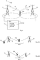
- Fig. 1 is a schematic overview of a portion of a communication network 1 to which the present embodiments can be applied.
- the communication network 1 is preferably a wireless, radio-based communication network or system providing communication services to connected user equipment(s) 300.
- the communication network 1 comprises multiple radio base stations 10, 20, also referred to as Node-B or base stations in the art. Each such radio base station 10, 20 provides communication services within a coverage area, typically denoted cell.
- the radio base stations 10, 20 are in turn connected to and controlled by a control network node 40, denoted Radio Network Controller (RNC) 40 in the art.
- RNC Radio Network Controller
- the user equipment 300 is in communication with multiple radio base stations 10, 20 over the radio interface.
- One of these radio base stations 10, 20 is then the so-called serving radio base station 10, whereas the at least one other radio base station 20 is denoted non-serving radio base station 20.
- downlink transmissions of user-specific data are typically only performed by the serving radio base station 10 on a downlink channel 14 towards the user equipment 300.
- uplink data transmissions from the user equipment 300 can on the contrary be received by not only the serving radio base station 10 but also by the at least one other radio base station 20.
- These uplink data transmissions are schematically illustrated by channels 12,22 in Fig. 1 .
- the serving radio base station 10 and the at least one other radio base station 20 form the so called active set of the user equipment 300. All radio base stations 10, 20 in the active set transmit some of the uplink related control channels as indicated in the background and schematically illustrated by the channels 14, 24 in Fig. 1 .
- a communication network 1 with a user equipment 300 having an active set of multiple radio base stations 10, 20 the uplink power of the user equipment 300 could be controlled by a non-serving radio base station 20.
- Figs. 2A and 2B illustrate such cases in connection with a user equipment 300 during soft handover (SHO).
- the user equipment 300 will be power-controlled by the non-serving radio base station 20 when G B > G A , wherein the Common Pilot Channel (CPICH) power of the serving radio base station 10 is G A P CPICH,A and the CPICH power of the non-serving radio base station 20 is G B P CPICH, B , where G A,B denotes respective path gain values.
- CPICH Common Pilot Channel
- the transmit power of the user equipment 300 is adjusted so that the quality at the non-serving radio base station 20 meets its defined target.
- P CPICH, B ⁇ P CPICH, A .
- the interference levels in the two cells can result in that the Signal-to-Interference (SIR) target is only met by the non-serving radio base station 20.
- the transmit power of the user equipment 300 can be set by the non-serving radio base station 20 so that some of the uplink control channels are too weak and cannot be correctly decoded or even detected at the serving radio base station 10.
- the SHO area is indicated by SHO and in Fig. 2B the point of serving cell change is indicated by an arrow.
- Multi-antenna transmission techniques for the uplink enable beam forming so that the user equipment pre-codes the signals so that these add coherently at a receiver.
- Another way to interpret beam forming is that the pre-coding vector applied at the user equipment creates a beam towards a particular radio base station. This means that the pre-coding will increase the link asymmetry, e.g. if the beam is directed towards the non-serving radio base station. Hence, the previously discussed problems will become even worse with multi-antenna uplink transmission.
- micro and/or pico radio base stations use less transmission power as compared to macro radio base stations.
- serving radio base station or cell changes are based on E C /I 0 (ratio of received energy per chip and the interference level) measurements. This will, however, result in that the cell border is moved towards the non-serving radio base station. The previously discussed problems will therefore become even worse with the introduction of micro and/or pico radio base stations.
- DPCCH P DPCCH I Self + I OtherCell + P n when the user equipment is scheduled
- P n denotes the power of the noise.
- the SIR will be significantly lower when a user equipment is not scheduled compared to when the user equipment is scheduled. Hence, the SIR will vary significantly depending on whether the user equipment is scheduled or not in a certain time slot.
- the present embodiments provide such a more efficient solution to the power control problems that can arise when a user equipment is in communication with both a serving radio base station and at least one other radio base station.
- the communication network is herein described as a Wideband Code Division Multiple Access (WCDMA) communication network.
- WCDMA Wideband Code Division Multiple Access
- GSM Global System for Mobile Communications
- LTE Long Term Evolution
- the user equipments 300 may be mobile stations such as mobile telephones ("cellular" telephones) or laptops with mobile termination and can thus be, for example, portable, pocket, hand-held, computer-included or car-mounted mobile devices which communicate voice and/or data with the communication network.
- the basic concept of the embodiments described herein is to introduce methods whereby the transmit power of an uplink control channel of a user equipment can be dynamically adapted based on existing feedback information available in the communication network.
- the power adaptation is performed by a power control device 100, 200 in the RNC 40, see Fig. 1 . Details of the preferred embodiments are described below.
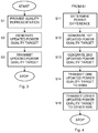
- Fig. 3 is a flow chart illustrating a power control method according to an embodiment.
- the present power control method is applied when a user equipment is in communication with a serving radio base station and at least one other radio base station, i.e. has at least two radio base stations in its active set.
- An example of such a situation is during SHO.
- the embodiments are, however, not limited thereto. Also other situations where the user equipment has uplink channels to multiple radio base stations are possible and within the scope of the embodiments. An example of such another situation is when radio base stations transmit multiple downlink streams of data to a user equipment.
- the method generally starts in step S1 where the RNC provides a quality representation of or for an uplink (UL) control channel from the user equipment to the serving radio base station.
- This provided quality representation hence, reflects and is indicative of a quality of the particular UL control channel to the serving radio base station.
- the RNC generates an updated power quality target for a reference control channel based on the quality representation provided in step S1.
- the RNC transmits the updated power quality target to at least one of the radio base stations in the active set of the user equipment. This will cause the at least one radio base station to send at least one transmit power control (TPC) command to the user equipment to thereby adjust the transmit power of the UL control channel.
- TPC transmit power control
- the term power quality refers to any suitable measure or estimate of the signal strength or power estimate for a particular channel.
- the power quality of a channel could preferably be represented by the SIR for that channel, or by the received power for that channel.
- the term power quality target could refer to e.g. SIR target or received power target.
- a radio base station such as the serving radio base station
- the active set of the user equipment When a radio base station, such as the serving radio base station, in the active set of the user equipment receives the updated power quality target from the RNC, it will compare this updated power quality target with the current power quality for the reference control channel for the user equipment. In the case when the current power quality for the reference control channel for the user equipment is lower than the updated power quality target generated by the RNC, the radio base station will send TPC commands to the user equipment to increase the transmit power of the UL control channel, i.e. the radio base station will send so-called TPC UP commands to the user equipment. The radio base station will continue to send TPC UP commands to the user equipment until the current power quality for the reference control channel for the user equipment corresponds to the updated power quality target generated by the RNC.
- the radio base station will instead send TPC commands to the user equipment to decrease the transmit power of the UL control channel, i.e. the radio base station will send so-called TPC DOWN commands to the user equipment, until the current power quality for the reference control channel for the user equipment corresponds to the updated power quality target generated by the RNC.
- the UL control channel for which a quality representation is provided in step S1 is preferably a control channel that is used by the user equipment for transmitting downlink feedback information to the serving radio base station.
- the UL control channel is preferably used by the user equipment for transmitting Hybrid Automatic Repeat request (HARQ) acknowledgements/non-acknowledgements (ACKs/NACKs) and/or Channel Quality Information/Pre-Coding Informarion (CQI/PQI) to the serving radio base station.
- HARQ Hybrid Automatic Repeat request
- ACKs/NACKs acknowledgements/non-acknowledgements
- CQI/PQI Channel Quality Information/Pre-Coding Informarion
- a preferred implementation embodiment that is adapted to a communication network employing WDCMA/High Speed Packet Access (WCDMA/HSPA) is when the UL control channel is a High Speed Dedicated Physical Control Channel (HS-DPCCH).
- the quality representation could be based solely on the quality of the UL control channel, preferably HS-DPCCH. In an alternative approach, it could be based on the quality situation of this UL control channel and at least one other UL control channel and/or at least one UL data channel.
- An example, of the latter is the Enhanced Dedicated Channel (E-DCH).
- the quality representation could, for instance, be a combined quality estimate of the quality at the HS-DPCCH and the E-DCH. Different combinations are possible, such as adding a weighted combination, an average quality value, etc.
- the reference control channel for which the updated power quality target is generated in step S2 is preferably a physical control channel that is received by all radio base stations in the active set.
- the transmit power of the reference control channel is used as a reference for the transmit power of all other physical channels.
- a preferred implementation embodiment that is adapted to a communication network employing WCDMA/HSPA is when the reference control channel is a Dedicated Physical Control Channel (DPCCH).
- DPCCH Dedicated Physical Control Channel
- TPC commands are generally transmitted on UL related control channels that are sent by the serving radio base station and the at least one other radio base station.
- this UL related control channel is the previously mentioned Fractional Dedicated Physical Channel (F-DPCH) that is sent by all radio base stations in the active set for the user equipment.
- F-DPCH Fractional Dedicated Physical Channel
- TPC is a general technique used to prevent too much unwanted interference between different transmitters and receivers in a communication network. The idea of using TPC is to automatically reduce the used transmission power of a user equipment to thereby reduce any interference problems and in addition receive an increased battery capacity of the user equipment.
- the RNC sends the updated power quality target to at least one radio base station in the active set.
- the RNC transmits the updated power quality target to only a single radio base station in the active set, such as the serving radio base station.
- the RNC transmits an updated power quality target to all radio base stations in the active set or to a portion of the radio base stations. In these two latter embodiments, the same updated power quality target could be sent to the radio base stations or different updated power quality targets could be sent to different radio base stations as is further disclosed here below.
- the updated power quality target could be an updated Outer Loop Power Control (OLPC) target for radio base stations in the active set.
- OPC Outer Loop Power Control
- Fig. 4 is a flow chart illustrating an embodiment of the generating step S2 and transmitting step S3 of Fig. 3 .
- the RNC takes the difference in transmit power between the serving radio base station and the non-serving radio base station(s) into account when determining the updated power quality target for the radio base stations in the active set.
- This power difference such as between the CPICH in the different radio base stations, is a configurable value and is known by the RNC or can be sent to the RNC.
- the power difference between the serving radio base station and the non-serving radio base station is determined in step S11.
- a step S12 a first updated power quality target is generated based on the quality representation that was provided in step S1 of Fig.
- a second updated power quality target is generated based on this first updated power quality target in combination with the power difference between the different radio base stations as determined in step S11.
- one of the generated updated power quality targets is transmitted to the serving radio base station, and in a step S15 the other generated updated power quality target is transmitted to the non-serving radio base station.
- the Inner Loop Power Control (ILPC) behavior will be similar as if both the serving and the non-serving radio base station used the same power quality target but where the effective path gain between the user equipment and the non-serving radio base station was h(x) dB smaller. This would be one way to prevent too low received power in the serving radio base station and thus protect the quality of the UL control channel.
- ILPC Inner Loop Power Control
- Fig. 5 is a flow chart illustrating an alternative power control method when a user equipment is in communication with a serving radio base station and at least one other radio base station.
- the providing step S31 basically corresponds to the providing step S1 of Fig. 3 and is therefore not further discussed herein.
- the RNC In a next step S32 the RNC generates an updated power offset for the UL control channel, preferably HS-DPCCH, relative the reference control channel, preferably DPCCH, based on the quality representation provided in step S31.
- the RNC transmits the updated power offset to the user equipment in order to trigger the user equipment to adjust the transmit power of the UL control channel, based on the updated power offset generated in step S32 and the transmit power of the reference control channel.
- the transmit power for the reference control channel is used as reference for all other physical channels transmitted by the user equipment.
- the transmit power of all other physical channels have a power offset relative to the reference control channel.
- the power offsets for the different physical channels are defined by different semi-static quantized amplitude ratios that are signaled by the RNC to the user equipment on the different physical channels.
- P HS-DPCCH and P DPCCH are the transmit powers associated with the HS-DPCCH and DPCCH respectively
- ⁇ hs and ⁇ c are semi-static quantized amplitude ratios that are signaled by the RNC.
- an increased power offset could be implemented as a higher ratio ⁇ hs / ⁇ c signaled by the RNC to the user equipment.
- a decreased power offset could be implemented as a lower ratio ⁇ hs / ⁇ c signaled by the RNC to the user equipment.
- the updated power offset for the HS-DPCCH (UL control channel) relative the DPCCH (reference control channel) generated in step S32 of Fig. 5 is lower than the original power offset, the user equipment will decrease the transmit power for the UL control channel.
- the RNC When the RNC has determined an updated power offset (an updated configuration for ⁇ hs / ⁇ c ) for the UL control channel relative the reference control channel for a user equipment, the RNC could also store the current active set of radio base stations associated with that user equipment. Then the RNC can base its configuration of ⁇ hs / ⁇ c for future user equipments with a similar active set on this updated power offset. This approach would allow the RNC to "learn" what an appropriate ⁇ hs / ⁇ c for a particular active set is.
- the methods illustrated in Fig. 3 and Fig. 5 both result in that the transmit power of the UL control channel for the user equipment is dynamically adapted based on a quality representation provided by the RNC. There is however a difference between the methods in how the adaptation of the transmit power is performed.
- the RNC first sends an updated power quality target to the radio base stations in the active set, and then a radio base station triggers the adaptation of the transmit power by sending TPC commands to the user equipment to adapt the transmit power of the UL control channel.
- the RNC more directly triggers the adaptation of the transmit power by sending an updated power offset directly to the user equipment to adapt the transmit power of the UL control channel.
- a TPC UP command will cause an increase in P DPCCH at the user equipment.
- an updated (higher) power offset ⁇ hs / ⁇ c will also lead to an increase in the transmit power of the HS-DPCCH but not necessarily of the DPCCH.
- these two techniques of achieving an increase in transmit power of the UL control channel can be combined.
- the RNC determines both an updated power quality target and an updated power offset based on the quality representation.
- the updated power quality target is transmitted to at least one radio base station in the active set of the user equipment, whereas the updated power offset is transmitted to the user equipment.
- the transmit power of the UL control channel P HS-DPCCH
- the transmit power of the UL control channel can be increased due to both i) an increase in P DPCCH caused by transmission of TPC UP commands from the at least one radio base station and ii) an increase in ⁇ hs / ⁇ c .
- the quality representation provided by the RNC in step S1 of Fig. 3 and step S31 in Fig. 5 can be any representation of the quality of the UL control channel, preferably in the form of a HS-DPCCH quality representation or estimate.
- the quality representation can be provided in a number of ways, and some examples will be given below.
- Fig. 6 is a flow chart illustrating an embodiment of the providing steps S1 of Fig. 3 and S31 of Fig. 5 , respectively.
- the quality of the UL control channel preferably HS-DPCCH
- the RNC dynamically measuring the UL asymmetry, i.e. the difference in effective path gain associated with the serving radio base station and the non-serving radio base station(s).
- the UL asymmetry is determined by the RNC.
- a quality representation for the UL control channel, preferably HS-DPCCH is generated by the RNC based on this UL asymmetry. This quality representation is then used in step S2 of Fig. 3 to provide basis for generating the updated power quality target, and/or in step S32 of Fig. 5 to provide basis for generating the updated power offset.
- the RNC dynamically measures the UL asymmetry between the serving radio base station and the non-serving radio base station(s) by monitoring the radio link control (RLC) retransmissions frequency on the UL control channel, preferably HS-DPCCH, for a user equipment.
- RLC radio link control
- a high UL asymmetry can cause an increase in RLC retransmissions frequency due to poor channel quality.
- the RNC can thus count the number of RLC retransmissions during a defined time period and use that number to determine the quality representation.
- the RNC dynamically measures the UL asymmetry between the serving radio base station and the non-serving radio base station(s) by monitoring the fraction of packets received on an enhanced UL channel, preferably the E-DCH, from the serving radio base station. If most of these packets come from the serving radio base station it is an indication that the serving radio base station is strong, i.e. there are no problems with the UL control channel. But if most packets come from the non-serving radio base station, i.e. a smaller portion comes from the serving radio base station, there might be a problem with the quality of the UL control channel.
- an enhanced UL channel preferably the E-DCH
- the RNC could determine the fraction of packets received on E-DCH from the serving radio base station for a user equipment relative the total number of packets received on the E-DCH.
- the UL asymmetry can be characterized as a function of the fraction of packets received from the serving radio base station. The quality representation is then determined based on that function.
- Fig. 7 illustrates an additional step S61 preceding the determining step S51 of Fig. 6 .
- the RNC receives, from the user equipment using existing radio resource control (RRC) signaling, quality reports on signal quality for a downlink common pilot channel (CPICH) for the radio base stations in the active set.
- the quality report can be based on E C /N 0 (ratio of received energy per chip and the noise level) measurements or path loss measurements, e.g. measurements of Received Signal Code Power (RSCP).
- the RNC determines in step S51 the UL asymmetry between the serving radio base station and the non-serving radio base station(s) based on the quality reports from the user equipment for the downlink common pilot channel (CPICH).
- RRC radio resource control
- the uplink link budget towards the non-serving radio base stations is stronger than the link budget towards the serving radio base station, which means that there is high UL asymmetry.
- the quality reports can be used to determine the quality representation.
- Fig. 8 illustrates an additional step S71 preceding the determining step S51 of Fig. 6 .
- the RNC receives quality reports, from the serving radio base station (SRBS), on signal quality for a reference control channel, preferably DPCCH, for the user equipment based on power quality measurements, preferably SIR measurements, made by the serving radio base station.
- the RNC determines in step S51 the UL asymmetry between the serving radio base station and the non-serving radio base station(s) based on the quality reports from the serving radio base station.
- the RNC can therefore use these quality reports based on SIR measurements when determining the quality representation.
- the RNC itself determines the quality representation.
- the embodiments are, though, not limited thereto.
- Other devices, such as the serving radio base station or the user equipment, in the communication network could instead determine the quality representation and transmit it to the RNC.
- the quality representation for the UL control channel can be determined based on at least two of the techniques disclosed in the foregoing.
- the quality representation can relate to any combination of i) monitoring the RLC retransmissions frequency on an UL control channel, preferably HS-DPCCH, ii) monitoring the fraction of packets received on an enhanced UL channel, preferably E-DCH, from the serving radio base station, iii) monitoring signal quality or path loss measurements on the downlink CPICH reported from the user equipment, iv) monitoring power quality measurements, preferably SIR measurements, made by the serving radio base station on a reference control channel, preferably DPCCH.
- Fig. 9 is a flow chart illustrating an embodiment of the providing steps S1 of Fig. 3 and S31 of Fig. 5 , respectively.
- the RNC receives a quality representation for the UL control channel, preferably HS-DPCCH, from the serving radio base station, based on measurements of the UL quality associated with a user equipment performed by the serving radio base station.
- the serving radio base station can transmit the quality representation, for instance, over Node-B Application Part (NBAP).
- NBAP Node-B Application Part
- the RNC receives the quality representation for the UL control channel, preferably HS-DPCCH, from the serving radio base station.
- This quality representation is then passed on to step S2 of Fig. 3 and/or step S32 of Fig. 5 , respectively.
- the serving radio base station determines and transmits the quality representation to the RNC.
- the serving radio base station measures the UL quality associated with a user equipment by measuring the power quality on the reference control channel, preferably the DPCCH SIR. If the SIR on DPCCH is low compared to the SIR target it is an indication of a poor UL quality. The serving radio base station will then generate a quality representation for the UL control channel, preferably HS-DPCCH, based on these measurements and transmit this quality representation to the RNC.
- the reference control channel preferably the DPCCH SIR.
- the serving radio base station measures the UL quality associated with a user equipment by measuring the demodulation performance on an uplink dedicated data channel, preferably the E-DCH Dedicated Physical Data Channel (E-DPDCH).
- the demodulation performance corresponds to the probability that the UL control channel, preferably HS-DPCCH, cannot be correctly decoded at the serving radio base station. If the UL quality is poor, there is a high probability that the UL control channel, preferably HS-DPCCH, cannot be correctly decoded at the serving radio base station.
- the serving radio base station will then generate a quality representation for the UL control channel, preferably HS-DPCCH, based on these measurements and transmit this quality representation to the RNC.
- the serving radio base station measures the UL quality associated with a user equipment by measuring the frequency with which the serving radio base station fails to detect transmission, such as HARQ-ACK/NACK, on the UL control channel, preferably HS-DPCCH, even though it has scheduled data on the downlink. If the HARQ ACKs/NACKs, indicating whether the user equipment was able to decode transmitted downlink transport blocks, are not detected or erroneously decoded, it is an indication that the quality of the UL control channel is inferior. The serving radio base station will then generate a quality representation for the UL control channel, preferably HS-DPCCH, based on these measurements and transmit this quality representation to the RNC.
- HARQ-ACK/NACK indicating whether the user equipment was able to decode transmitted downlink transport blocks
- the quality representation for the UL control channel can be determined based on at least two of the techniques disclosed in the foregoing.
- the quality representation can relate to any combination of i) measuring the power quality on the reference control channel, preferably DPCCH SIR, ii) measuring the demodulation performance on an uplink dedicated data channel, preferably E-DPDCH, iii) measuring the frequency with which the serving radio base station fails to detect transmission on the UL control channel, preferably HS-DPCCH, even though it has scheduled data on the downlink.
- Fig. 10 is a flow chart illustrating an embodiment of the providing steps S1 of Fig. 3 and S31 of Fig. 5 , respectively.
- the RNC receives a quality representation for the UL control channel, preferably HS-DPCCH, from the user equipment, based on measurements of the UL quality at the serving radio base station performed by the user equipment.
- the RNC receives the quality representation for the UL control channel, preferably HS-DPCCH, from the user equipment.
- This quality representation is then passed on to step S2 of Fig. 3 and/or step S32 of Fig. 5 , respectively.
- the user equipment determines and transmits the quality representation to the RNC.
- the user equipment compares the HARQ-ACK messages it has transmitted on the UL control channel, preferably HS-DPCCH, to the serving radio base station with the packet transmission that it receives on a downlink channel from the serving radio base station.
- the user equipment previously has successfully received a packet on the downlink channel and transmitted a HARQ-ACK on the UL control channel to the serving radio base station with the regard to that packet, but anyway receives a retransmission of the same packet and/or an increased redundancy version, then this is an indication that the UL control channel quality at the serving radio base station is inferior.
- the user equipment generates the quality representation for the UL control channel, preferably HS-DPCCH, based on a comparison of transmission acknowledgement messages transmitted on the UL control channel with packet transmissions received on a downlink data channel from the serving radio base station. This quality representation is then transmitted to the RNC.
- the quality representation for the UL control channel, preferably HS-DPCCH, based on a comparison of transmission acknowledgement messages transmitted on the UL control channel with packet transmissions received on a downlink data channel from the serving radio base station. This quality representation is then transmitted to the RNC.
- the user equipment monitors for TPC commands received from the serving radio base station and generates the quality representation based on these received TPC commands.
- the user equipment detects a significant amount of TPC UP commands from the serving radio base station during a defined time period, this is an indication that the UL control channel, preferably HS-DPCCH, quality is inferior and that the user equipment could be power-controlled by a non-serving radio base station.
- the user equipment generates the quality representation based on monitoring of TPC commands transmitted from the serving radio base station to the user equipment.
- the quality representation could then be an indication of the percentage of the TPC commands that, during a defined time period or a defined number of TPC commands, indicate an increase in transmit power of the user equipment.
- An alternative but related approach is to determine the quality representation based on the percentage of the TPC commands from the serving radio base station that indicate a decrease in transmit power of the user equipment, i.e. so-called TPC DOWN commands.
- the quality representation for the UL control channel, preferably HS-DPCCH, generated by the user equipment is then transmitted to the RNC.
- the user equipment estimates the difference in downlink (DL) path loss between the serving radio base station and the at least one other non-serving radio base station.
- DL path loss downlink path loss
- Such a downlink path loss based procedure can be performed based on path loss estimations of a respective pilot channel, such as CPICH, from the radio base stations in the active set.
- the path losses represent the reduction in power density or attenuation of the signals transmitted from the radio base stations towards the user equipment.
- the path loss may be due to various effects, such as free-space loss, refraction, diffraction, reflection and absorption.
- the path losses can be estimated or predicted by the user equipment according to methods well known in the art, such as statistical or stochastic methods or deterministic methods.
- the user equipment generates the quality representation for the UL control channel, preferably HS-DPCCH, based on estimating the difference in downlink path loss between the serving radio base station and the at least on other radio base station. This quality representation is then transmitted to the RNC.
- the quality representation for the UL control channel, preferably HS-DPCCH, based on estimating the difference in downlink path loss between the serving radio base station and the at least on other radio base station. This quality representation is then transmitted to the RNC.
- the user equipment generates the quality representation for the UL control channel, preferably HS-DPCCH, based on a combination of at least two of the above presented embodiments.
- the quality representation is determined based on at least two of the techniques disclosed in the foregoing and relating to i) comparing transmitted HARQ ACK/NACK messages with received data packets, ii) monitoring TPC commands from the serving radio base station and iii) estimating DL path loss difference.
- a quality representation that is determined as a combination of a quality representation value as determined by the RNC, a quality representation value as received from the serving radio base station, and/or a quality representation value as received from the user equipment.
- Fig. 11 is a flow chart illustrating an embodiment of the providing steps S1 of Fig. 3 and S31 of Fig. 5 , respectively.
- the RNC determines multiple quality estimates for the UL control channel, preferably HS-DPCCH, at different time instances.
- the RNC can be configured to perform this step S81 over a predefined period of time to thereby determine the quality estimates during this period of time.
- the RNC is configured to determine a predefined number of quality estimates.
- the quality estimates determined in step S81 are obtained according to any of the previously described embodiments.
- the RNC then has access to multiple quality estimates reflecting the quality of the UL control channel at multiple different time instances: Q HS - DPCCH ( t ), Q HS - DPCCH ( t - 1),..., Q HS - DPCCH ( t - M), M ⁇ 1.
- Q HS - DPCCH ( t ) Q HS - DPCCH ( t - 1),..., Q HS - DPCCH ( t - M), M ⁇ 1.
- the quality representation is in this embodiment a function of the multiple quality estimates, i.e. f( QHS-DPCCH ( t ), Q HS-DPCCH ( t- 1),... , Q HS-DPCCH ( t - M )).
- Fig. 11 also illustrates a particular example of a function that can be used according to the embodiments to calculate the quality representation.
- the quality representation is calculated as an average of the multiple quality estimates determined in step S81.
- the quality representation is thereby calculated as Q HS ⁇ DPCCH t , Q HS ⁇ DPCCH t ⁇ 1 , ... , Q HS ⁇ DPCCH t ⁇ M M + 1 .
- the quality representation reflects an average quality situation for the UL control channel, preferably HS-DPCCH, during the time for which the quality estimates have been determined in step S81.
- This quality representation is then passed on to step S2 of Fig. 3 and/or step S32 of Fig. 5 , respectively.
- the function f( ) does not output the average of the multiple quality estimates but rather the median of the multiple quality estimates. Also this embodiment will calculate a quality representation that reflects an average quality situation for the UL control channel, preferably HS-DPCCH.
- Fig. 12 is a flow chart illustrating another embodiment of the providing steps S1 of Fig. 3 and S31 of Fig. 5 , respectively.
- the RNC determines multiple quality estimates for the UL control channel, preferably HS-DPCCH, at different time instances.
- This step S91 basically corresponds to step S81 of Fig. 11 and is therefore not further discussed herein.
- another function f( ) than calculating an average or median of the quality estimates is used to get the quality representation.
- step S92 selects the maximum quality estimate among the quality estimates determined in step S91 and uses this selected quality estimate as the quality representation for the UL control channel, preferably HS-DPCCH.
- the quality representation is max ( Q HS-DPCCH ( t ), Q HS-DPCCH ( t - 1 ),..., Q HS-DPCCH ( t - M )).
- the user equipment investigates whether the quality for the UL control channel, preferably HS-DPCCH, lies below the quality represented by a threshold value for the time period during which the quality estimates are determined. Such a situation then indicates a poor HS-DPCCH quality.
- This quality representation for the UL control channel is then passed on to step S2 of Fig. 3 and/or step S32 of Fig. 5 , respectively.
- the function f ( ) instead selects the minimum quality estimate among the multiple quality estimates.
- the quality representation is min( Q HS-DPCCH ( t ), Q HS-DPCCH ( t - 1 ),..., Q HS-DPCCH ( t - M )). This embodiment is particularly suitable for a situation with excessive quality of the HS-DPCCH.
- Fig. 13 illustrates an additional step S21 of the embodiments shown of Fig. 3 and Fig. 5 .
- the quality representation that was provided in step S1 of Fig. 3 , or step S31 of Fig. 5 is compared with a threshold value.
- the user equipment investigates whether f ( Q HS-DPCCH ( t ), Q HS-DPCCH ( t - 1 ),..., Q HS-DPCCH ( t - M )) ⁇ Q 1 , where Q 1 represents the threshold value.
- a low value of the quality representation indicates a poor quality of the UL control channel, preferably HS-DPCCH.
- step S21 preferably investigates whether the quality representation exceeds the threshold value. This would then indicate a poor channel quality and a high probability that the user equipment is power controlled by a non-serving radio base station.
- step S21 of Fig. 13 preferably investigates whether the quality of the UL control channel, preferably HS-DPCCH, as indicated by the quality representation, is poorer or worse than a threshold quality, as represented by the threshold value.
- the RNC should in step S2 of Fig. 3 generate an updated power quality target, and/or in step S32 of Fig. 5 generate an updated power offset, where the updated power quality target/power offset is selected to combat the poor channel quality.
- a poor quality of the UL control channel, preferably HS-DPCCH suggests that the power quality target for the reference control channel, preferably DPCCH, should be increased in order to ensure proper detection and decoding of the UL control channel, preferably HS-DPCCH.
- the power offset for the UL control channel, preferably HS-DPCCH, relative the reference control channel, preferably DPCCH should be increased in order to ensure proper detection and decoding of the UL control channel, preferably HS-DPCCH.
- the updated power quality target/power offset generated by the RNC in step S2 of Fig. 3 and/or step S32 of Fig. 5 should preferably be kept at the same level as before.
- the present embodiments can in fact also be used in a situation where the quality of the UL control channel, preferably HS-DPCCH, is excessive.
- a quality representation is provided for the UL control channel as previously disclosed herein in connection with step S1 of Fig. 3 and/or step S31 of Fig. 5 .
- This quality representation is then compared to a threshold value in step S21.
- the threshold value is preferably different from that in the previously disclosed embodiments.
- the threshold value preferably indicates a threshold for a maximum desirable quality for the UL control channel.
- the RNC advantageously provides the quality representation in this embodiment according to any of the embodiments discussed herein.
- This quality representation is then compared to the threshold value and if the quality representation exceeds the threshold value this indicates an excessive high quality of the UL control channel (or in an alternative embodiment if the quality representation is below the threshold value this indicates an excessive high quality) and then the updated power quality target/power offset generated by the RNC in step S2 of Fig. 3 and/or step S32 of Fig. 5 should preferably be decreased.
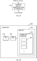
- Fig. 15 is a schematic block diagram of an embodiment of a power control device 100 according to an embodiment.
- the power control device 100 is configured to be implemented in a RNC in a communication network.
- the power control device 100 comprises a representation provider 110 that is configured to provide a quality representation of an UL control channel, preferably HS-DPCCH, from the user equipment to its serving radio base station.
- the power control device 100 further comprises a power quality target generator 120 configured to generate an updated power quality target for the reference control channel, preferably DPCCH, based on the quality representation provided by the representation provider 110.
- the power control device 100 also comprises a transmitter 130 configured to transmit the updated power quality target generated by the power quality target generator 120 to at least one of the radio base stations in the active set of the user equipment. This will cause at least one radio base station in the active set of the user equipment to send at least one TPC command to the user equipment to adjust the transmit power of the UL control channel.
- the power control device 100 also comprises a power determiner 140 which is configured to determine a difference in transmit power between the serving radio base station and the non-serving radio base station. The power levels of individual radio base stations could then be signaled to the radio base station with the power determiner 140, which then calculates the power difference. Alternatively, the RNC determines the power difference.
- the power determiner 140 is illustrated with a dotted line in Fig. 15 indicating that it is part of an alternative embodiment and can be omitted from the basic block diagram of the power control device 100.
- the power difference determined by the power determiner 140 is then used by the power quality target generator 120 to generate a second updated power quality target based on a first updated power quality target and the power difference, where the first updated power quality target is generated based on the quality representation provided by the representation provider 110.
- the transmitter 130 in this embodiment will then transmit one of the updated power quality targets to the serving radio base station and the other updated power quality target to the non-serving radio base station.
- Fig. 16 is a schematic block diagram of an alternative power control device 100.
- the representation provider 210 basically corresponds to the representation provider 110 in Fig. 15 and is therefore not further discussed herein.
- the power control device 100 further comprises a power offset generator 220 configured to generate an updated power offset for the UL control channel, preferably HS-DPCCH, relative a reference control channel, preferably DPCCH, based on the quality representation provided by the representation provider 210.
- the power control device 100 also comprises a transmitter 230 configured to transmit the updated power offset generated by the power offset generator 220 to the user equipment in order to trigger the user equipment to adjust the transmit power of the UL control channel, based on the updated power offset generated by the power offset generator 220 and the transmit power of the reference control channel.
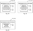
- Fig. 17 is a schematic block diagram of an embodiment of the representation provider 110, 210 in Fig. 15 and Fig. 16 , respectively.
- the representation provider 110, 210 comprises an uplink asymmetry determiner 111,211 configured to determine an UL asymmetry, i.e. the difference in effective path gain associated with the serving radio base station and the non-serving radio base station(s).
- the representation provider 110, 210 further comprises a representation generator 112, 212 configured to generate the quality representation for the UL control channel, preferably HS-DPCCH, based on the UL asymmetry between the serving radio base station and the non-serving radio base station(s) determined by the uplink asymmetry determiner 111, 211.
- the uplink asymmetry determiner 111, 211 may be realized in different ways. According to an embodiment the uplink asymmetry determiner 111, 211 measures the UL asymmetry between the serving radio base station and the non-serving radio base station(s) by monitoring the RLC retransmissions frequency on the UL control channel, preferably HS-DPCCH, for the user equipment. Generally a high UL asymmetry can cause an increase in RLC retransmissions frequency due to poor channel quality. The uplink asymmetry determiner 111, 211 can thus count the number of RLC retransmissions during a defined time period and use that number to determine the UL asymmetry.
- the uplink asymmetry determiner 111, 211 can thus count the number of RLC retransmissions during a defined time period and use that number to determine the UL asymmetry.
- the uplink asymmetry determiner 111, 211 measures the UL asymmetry between the serving radio base station and the non-serving radio base station(s) by monitoring the fraction of packets received by a receiver 160 (illustrated with a dotted line in Fig. 15 ), 250 (illustrated with a dotted line in Fig. 16 ) in the power control device 100, 200 on an enhanced UL channel, preferably E-DCH, from the serving radio base station. If most of these packets come from the serving radio base station it is an indication that the serving radio base station is strong, i.e. there are no problems with the UL control channel. But if most packets come from the non-serving radio base station (i.e.
- the uplink asymmetry determiner 111, 211 could determine the fraction of packets received on E-DCH from the serving radio base station for a user equipment relative the total number of packets received on the E-DCH. The UL asymmetry can then be determined based on a function of the fraction of packets received from the serving radio base station.
- the receiver 160, 250 (illustrated with a dotted line in Fig. 15 and Fig. 16 ) in the power control device 100, 200 is employed for communication, preferably wireless radio-based communication, with radio base stations in the communication network.
- the uplink asymmetry determiner 111, 211 estimates the UL asymmetry between the serving radio base station and the non-serving radio base station(s) based on a quality report on signal quality for a downlink common pilot channel (CIPCH) for the radio base stations in the active set, received from the user equipment by a receiver 160 (illustrated with a dotted line in Fig. 15 ), 250 (illustrated with a dotted line in Fig. 16 ) in the power control device 100, 200.
- the quality report can be based on E C /N 0 measurements or path loss measurements, e.g. measurements of RSCP.
- the uplink asymmetry determiner 111, 211 determines the UL asymmetry between the serving radio base station and the non-serving radio base station(s) based on the quality reports from the user equipment for the CPICH. If the pilot power of the downlink is lower in the non-serving radio base station than in the serving radio base station, the uplink link budget towards the non-serving radio base stations is stronger than the link budget towards the serving radio base station, which means that there is high UL asymmetry. Hence, the quality reports can be used to determine the UL asymmetry.
- the uplink asymmetry determiner 111, 211 estimates the UL asymmetry between the serving radio base station and the non-serving radio base station(s) based on a report on signal quality based on power quality measurements, preferably SIR measurements, on the reference control channel, preferably DPCCH, received from the serving radio base station by a receiver 160 (illustrated with a dotted line in Fig. 15 ), 250 (illustrated with a dotted line in Fig. 16 ) in the power control device 100, 200. If there is a significant difference in SIR on the reference control channel for the serving radio base station and the non-serving radio base station(s) then this indicates a high UL asymmetry between the serving radio base station and the non-serving radio base station(s).
- Fig. 20 is a schematic block diagram of another embodiment of the representation provider 110, 210 in Fig. 15 and Fig. 16 , respectively.
- the representation provider here comprises a representation receiver 116, 216 configured to receive the quality representation for the UL control channel, preferably HS-DPCCH, from the serving radio base station, based on measurements of the UL quality associated with a user equipment performed by the serving radio base station.
- the representation receiver 116, 216 can be configured to receive the quality representation for the UL control channel, preferably HS-DPCCH, from the user equipment, based on measurements of the UL quality at the serving radio base station performed by the user equipment.
- the receiver 160 in Fig. 15 or the receiver 250 in Fig. 16 could operate as representation receiver.
- the representation receiver 115, 116 can then be omitted.
- the serving radio base station could then determine the quality representation for the UL control channel, preferably HS-DPCCH, as previously disclosed herein, i.e. based on i) measurements of the power quality on the reference control channel, preferably DPCCH SIR, ii) measurements of the demodulation performance on an uplink dedicated data channel, preferably E-DPDCH, iii) measurements of the frequency with which the serving radio base station fails to detect transmission (such as HARQ-ACK/NACK) on the UL control channel, preferably HS-DPCCH, even though it has scheduled data on the downlink, or iv) a combination of any of i) to iii).
- the UL control channel preferably HS-DPCCH
- the user equipment could then determine the quality representation for the UL control channel, preferably HS-DPCCH, as previously disclosed herein, i.e. based on i) a comparison of transmitted HARQ-ACK/NACK messages and received data packets, ii) monitoring TPC commands transmitted from the serving radio base station, iii) an estimation of the difference in path loss to the serving radio base station and to the non-serving radio base station, or iv) a combination of any of i) to iii).
- the quality representation for the UL control channel preferably HS-DPCCH
- Fig. 18 is a schematic block diagram of an embodiment of the representation provider 110, 210 in Fig. 15 and Fig. 16 , respectively.
- the representation provider 110, 210 comprises a quality estimator 113, 213 configured to determine multiple quality estimates for the UL control channel, preferably HS-DPCCH, at different time instances. The quality estimator 113, 213 could then determine these quality estimates as previously disclosed herein.
- the representation provider 110, 210 further comprises a calculator 114, 214 configured to calculate the quality representation based on the multiple quality estimates determined by the quality estimator 113, 213. In this embodiment, the calculator 114, 214 could calculate the quality representation base on an average of the multiple quality estimates or as a median of the multiple quality estimates.
- Fig. 19 is a schematic block diagram of another embodiment of the representation provider 110, 210 in Fig. 15 and Fig. 16 , respectively.
- the representation provider 110, 210 comprises the previously described quality estimator 113, 213.
- the representation generator 110, 210 comprises a selector 115, 215 that is configured to select a maximum quality estimate among the multiple quality estimates from the quality estimator 113, 213 as the quality representation for the UL control channel, preferably HS-DPCCH,.
- the selector 115, 215 instead selects the minimum quality estimate as the quality representation.
- the embodiments of the representation provider 110, 210 illustrated in Figs. 18 and 19 could alternatively be implemented by arranging the quality estimator 113, 213 and the calculator 114, 214 or the quality estimator 113, 213 and the selector 115, 215 as separate units in the power control device 100,200.
- the power control device 100, 200 also comprises a comparator 150, 240 which is configured to compare the quality representation from the representation provider 110, 210 with a threshold value.
- the comparator 150, 240 is illustrated with a dotted line in Fig. 15 and Fig. 16 indicating that it is part of an alternative embodiment and can be omitted from the basic block diagram of the power control device 100, 200.
- the power quality target generator 120 will generate an updated power quality target based on the outcome of the comparison of the quality representation to the threshold value made by the comparator 150.
- the power offset generator 220 will generate an updated power offset based on the outcome of the comparison of the quality representation to the threshold value made by the comparator 240.
- the units 110-160 of the power control device 100 and the units 210-250 of the power control device 200 can be implemented in hardware, in software or a combination of hardware and software.
- the respective units 110-160 and 210-250 disclosed in conjunction with Figs. 15 and 16 and units 113, 213 and 114, 214 in Fig. 18 and units 113, 213 and 115, 215 in Fig. 19 have been disclosed as physically separate units 110-160 in the power control device 100 and the units 210-250 of the power control device 200, and all may be special purpose circuits, such as ASICs (Application Specific Integrated Circuits), alternative embodiments are possible where some or all of the units 110-160 and 210-250 are implemented as computer program modules running on a general purpose processor.
- ASICs Application Specific Integrated Circuits
- the power control device 100,200 can be implemented in a computer 400 comprising a general input/output (I/O) unit 410 in order to enable communication with the radio base stations in the communication network, a processing unit 420, such as a DSP (Digital Signal Processor) or CPU (Central Processing Unit).
- the processing unit 420 can be a single unit or a plurality of units for performing different steps of the methods described herein.
- the computer 400 also comprises at least one computer program product 430 in the form of a non-volatile memory, for instance an EEPROM (Electrically Erasable Programmable Read-Only Memory), a flash memory or a disk drive.
- EEPROM Electrical Erasable Programmable Read-Only Memory
- the computer program product 430 comprises a computer program 440, which comprises code means 450 which when run on the computer 400, such as by the processing unit 420, cause the computer 400 to perform the steps of the method described in the foregoing in connection with Fig. 3 and Fig. 5 .
- the code means 450 in the computer program 440 comprises a representation providing module for providing a quality representation, a generating module for generating an updated power quality target ( Fig. 3 ) or an updated power offset ( Fig. 5 ) and a transmitting module for transmitting the updated power quality target ( Fig. 3 ) or the updated power offset ( Fig. 5 ).
- These modules essentially perform the steps of the flow charts in Fig. 3 and/or Fig. 5 when run on the processing unit 420.
- the different modules 450 are run on the processing unit 420 they correspond to the corresponding units 110-130 of Fig. 15 and/or 210-230 of Fig. 16 .
- the computer program 440 may additionally comprise further modules performing steps as disclosed in connection with Fig. 4 and Figs. 6-13 .
- the embodiments as disclosed herein can be used to achieve a certain the DPCCH SIR quality at the serving radio base station for a user equipment when in communication with multiple radio base stations, such as during SHO. By ensuring such a sufficient HS-DPCCH quality at the serving radio base station the downlink HDSPA performance is not affected. By being able to provide sufficient HS-DPCCH quality the embodiments enable introduction of techniques, such as multi-antenna transmission techniques for the uplink, complementing traditional macro radio base stations with micro and/or pico radio base stations and per-HARQ scheduling for improving uplink orthogonality, in communication networks.
Claims (3)
- Leistungssteuerungsverfahren in einem Datenübertragungsnetz (1), wenn eine Benutzerausrüstung (300) über eine Funkschnittstelle auf Uplink-Kanälen (12, 22) mit einer versorgenden Funkbasisstation (10) und mindestens einer anderen Funkbasisstation (20) in Verbindung ist, wobei die versorgende Funkbasisstation (10) mit einer Funknetzsteuerung (40) verbunden wird, wobei das Verfahren umfasst:- die Funknetzsteuerung (40), die von der Benutzerausrüstung (300) eine Qualitätsdarstellung eines Uplink-Steuerkanals (12) von der Benutzerausrüstung (300) zu der versorgenden Funkbasisstation (10) empfängt (S111);- die Funknetzsteuerung (40), die eine Differenz beim Übertragen von Leistung zwischen der versorgenden Funkbasisstation (10) und der mindestens einen anderen Funkbasisstation (20) bestimmt (S11);- die Funknetzsteuerung (40), die ein erstes aktualisiertes Leistungsqualitätsziel für einen Uplink-Referenzsteuerkanal auf Grundlage der Qualitätsdarstellung erzeugt (S12);- die Funknetzsteuerung (40), die ein zweites aktualisiertes Leistungsqualitätsziel auf Grundlage des ersten aktualisierten Leistungsqualitätsziels und der Differenz beim Übertragen von Leistung erzeugt (S13);- die Funknetzsteuerung (40), die entweder das erste aktualisierte Leistungsqualitätsziel oder das zweite aktualisierte Leistungsqualitätsziel zu der versorgenden Funkbasisstation (10) überträgt (S14); und- die Funknetzsteuerung (40), die das andere des ersten aktualisierten Leistungsqualitätsziels oder des zweiten aktualisierten Leistungsqualitätsziels zu der mindestens einen anderen Funkbasisstation (20) überträgt (S 15), um die mindestens entweder eine versorgende Funkbasisstation (10) oder die mindestens andere Funkbasisstation (20) zu steuern, um mindestens einen Übertragungsleistungssteuerungsbefehl an die Benutzerausrüstung (300) zu übertragen, um eine Anpassung einer Übertragungsleistung des Uplink-Steuerkanals (12) auszulösen.
- Verfahren nach Anspruch 1, wobei die Funknetzsteuerung (40), die die Qualitätsdarstellung empfängt (S111), die Funknetzsteuerung (40) umfasst, die die durch die Benutzerausrüstung (300) auf Grundlage des Überwachens von Übertragungsleistungssteuerungsbefehlen erzeugte Qualitätsdarstellung empfängt (S111), die von der versorgenden Funkbasisstation (10) an die Benutzerausrüstung (300) übertragen wird.
- Leistungssteuerungsvorrichtung (100), die konfiguriert wird, in einer Funknetzsteuerung (40) in einem Datenübertragungsnetz (1) umgesetzt zu werden, wenn eine Benutzerausrüstung (300) mit einer versorgenden Funkbasisstation (10) und mindestens einer anderen Funkbasisstation (20) über eine Funkschnittstelle auf Uplink-Kanälen (12, 22) in Verbindung ist, wobei die versorgende Funkbasisstation (10) mit der Funknetzsteuerung (40) verbunden ist, wobei die Leistungssteuerungsvorrichtung (100) umfasst:- einen Darstellungsempfänger (116, 216), der konfiguriert wird, von der Benutzerausrüstung (300) eine Qualitätsdarstellung eines Uplink-Steuerkanals (12) von der Benutzerausrüstung (300) zu der versorgenden Funkbasisstation (10) zu empfangen;- einen Leistungsbestimmer (140), der konfiguriert wird, eine Differenz in Übertragungsleistung zwischen der versorgenden Funkbasisstation (10) und der mindestens einen anderen Funkbasisstation (20) zu bestimmen;- einen Leistungsqualitätszielgenerator (120), der konfiguriert wird, ein erstes aktualisiertes Leistungsqualitätsziel für einen Uplink-Referenzsteuerkanal auf Grundlage der Qualitätsdarstellung und ein zweites aktualisiertes Leistungsqualitätsziel für einen Uplink-Referenzsteuerkanal auf Grundlage des ersten aktualisierten Leistungsqualitätsziels und der Differenz in Übertragungsleistung zu erzeugen; und- einen Transmitter (130), der konfiguriert wird, entweder das erste aktualisierte Leistungsqualitätsziel oder das zweite aktualisierte Qualitätsziel an die versorgende Funkbasisstation (10) und das andere erste aktualisierte Leistungsqualitätsziel oder das zweite aktualisierte Qualitätsziel an die mindestens eine andere Funkbasisstation (20) zu übertragen, um mindestens entweder die versorgende Funkbasisstation (10) oder mindestens die eine andere Funkbasisstation (20) zu steuern, um mindestens einen Übertragungsleistungssteuerungsbefehl an die Benutzerausrüstung (300) zu übertragen, um eine Anpassung einer Übertragungsleistung des Uplink-Steuerkanals (12) auszulösen.
Applications Claiming Priority (2)
| Application Number | Priority Date | Filing Date | Title |
|---|---|---|---|
| US39208810P | 2010-10-12 | 2010-10-12 | |
| PCT/SE2011/051156 WO2012050506A1 (en) | 2010-10-12 | 2011-09-28 | Uplink power control |
Publications (3)
| Publication Number | Publication Date |
|---|---|
| EP2628341A1 EP2628341A1 (de) | 2013-08-21 |
| EP2628341A4 EP2628341A4 (de) | 2016-03-09 |
| EP2628341B1 true EP2628341B1 (de) | 2017-01-04 |
Family
ID=45938529
Family Applications (1)
| Application Number | Title | Priority Date | Filing Date |
|---|---|---|---|
| EP11832833.5A Active EP2628341B1 (de) | 2010-10-12 | 2011-09-28 | Uplink-leistungssteuerung |
Country Status (4)
| Country | Link |
|---|---|
| US (2) | US8855700B2 (de) |
| EP (1) | EP2628341B1 (de) |
| CN (1) | CN103155655A (de) |
| WO (2) | WO2012050507A1 (de) |
Families Citing this family (23)
| Publication number | Priority date | Publication date | Assignee | Title |
|---|---|---|---|---|
| EP2439986B1 (de) * | 2010-10-06 | 2018-08-15 | Mitsubishi Electric R&D Centre Europe B.V. | Verfahren zur bestimmung, unter welcher bedingung eine erste basisstation, die sich in einem energiesparmodus befindet, in einen anderen betriebsmodus umschalten muss |
| US9185660B2 (en) | 2011-04-21 | 2015-11-10 | Mediatek Inc. | Power adaptation apparatus and power adaptation method for controlling uplink/downlink power |
| WO2013051987A1 (en) * | 2011-10-04 | 2013-04-11 | Telefonaktiebolaget L M Ericsson (Publ) | Controlling uplink transmit power responsive to combination of received power control commands during soft handover in a communicaton system |
| WO2013089191A1 (ja) * | 2011-12-13 | 2013-06-20 | 京セラ株式会社 | 移動端末、無線通信システム、および無線通信方法 |
| WO2013133746A2 (en) * | 2012-03-06 | 2013-09-12 | Telefonaktiebolaget L M Ericsson (Publ) | A radio network controller, a serving base station, a user equipment and methods therein |
| US9756573B2 (en) | 2012-05-23 | 2017-09-05 | Telefonaktiebolaget Lm Ericsson (Publ) | Uplink power control |
| US8824411B2 (en) | 2012-05-24 | 2014-09-02 | Apple Inc. | Tune-away detection based adaptive link adaptation for hybrid transceivers |
| US9491664B2 (en) | 2012-08-03 | 2016-11-08 | Telefonaktiebolaget Lm Ericsson (Publ) | Base stations and nodes for use in a mobile communications network and methods of operating the same |
| US9130657B2 (en) * | 2012-10-19 | 2015-09-08 | Stmicroelectronics, Inc. | System and method for a power line modem |
| US20150304964A1 (en) | 2012-11-02 | 2015-10-22 | Telefonaktiebolaget L M Ericsson (Publ) | Methods and Apparatuses for Boosting Channel Transmission in a Network |
| US9232484B2 (en) | 2012-11-29 | 2016-01-05 | Qualcomm Incorporated | Apparatus and methods of HSPA transmit power control |
| WO2014093885A1 (en) * | 2012-12-13 | 2014-06-19 | Huawei Technologies Co., Ltd. | Systems and methods for power control in wireless networks |
| CN103874186B (zh) * | 2012-12-18 | 2017-11-17 | 华为技术有限公司 | 高速专用物理控制信道的功率控制方法及设备 |
| EP2981142A4 (de) * | 2013-04-12 | 2016-03-16 | Huawei Tech Co Ltd | Verfahren und benutzervorrichtung zur leistungskonfiguration in einem heterogenen netzwerk |
| WO2014182236A1 (en) * | 2013-05-10 | 2014-11-13 | Telefonaktiebolaget L M Ericsson (Publ) | Power control of uplink control channels in heterogeneous networks |
| US20150003234A1 (en) * | 2013-06-27 | 2015-01-01 | Alcatel-Lucent Usa Inc. | Methods and systems for caching content in a network |
| CN104348584B (zh) * | 2013-08-09 | 2017-12-19 | 上海贝尔股份有限公司 | 一种针对abs机制实现信道质量反馈和预测的方法 |
| US9986560B2 (en) * | 2013-11-27 | 2018-05-29 | Telefonaktiebolaget Lm Ericsson (Publ) | Method for allocation of time transmission intervals |
| WO2015142244A1 (en) * | 2014-03-21 | 2015-09-24 | Telefonaktiebolaget L M Ericsson (Publ) | System and method for improving uplink control channels for weak communication links |
| WO2015176205A1 (zh) * | 2014-05-19 | 2015-11-26 | 华为技术有限公司 | 终端控制方法、无线网络控制器和基站 |
| US9877288B2 (en) * | 2014-07-25 | 2018-01-23 | Futurewei Technologies, Inc. | System and method for transmit power control with secondary uplink pilot channel |
| US10630446B2 (en) * | 2015-10-21 | 2020-04-21 | Lg Electronics Inc. | Method for transmitting ACK/NACK response for broadcast signal/multicast signal in wireless communication system, and device therefor |
| US11937185B2 (en) * | 2021-08-26 | 2024-03-19 | Qualcomm Incorporated | Shared transmit power control for uplink shared and control channels |
Family Cites Families (33)
| Publication number | Priority date | Publication date | Assignee | Title |
|---|---|---|---|---|
| GB2358109B (en) | 2000-01-10 | 2004-03-24 | Fujitsu Ltd | Soft hand-off in cellular mobile communications networks |
| ATE372610T1 (de) * | 2000-02-21 | 2007-09-15 | Alcatel Lucent | Verfahren zur einstellung eines signalqualitätssollwertes während der sendeleistungsregelung in einem cdma- funkkomminikationsnetzwerk |
| WO2002003573A1 (fr) | 2000-07-03 | 2002-01-10 | Matsushita Electric Industrial Co., Ltd. | Unite de station de base et procede de radiocommunication |
| US20020094833A1 (en) * | 2001-01-12 | 2002-07-18 | Telefonaktiebolaget Lm Ericsson (Publ). | Downlink power control of a common transport channel |
| US6970716B2 (en) * | 2001-02-22 | 2005-11-29 | Telefonaktiebolaget Lm Ericsson (Publ) | Power control for downlink shared channel in radio access telecommunications network |
| KR100459573B1 (ko) * | 2001-08-25 | 2004-12-03 | 삼성전자주식회사 | 고속 순방향 패킷 접속 방식을 사용하는 통신 시스템에서역방향 전송 전력 오프셋과 고속 순방향 공통 채널 전력레벨을 송수신하는 장치 및 방법 |
| KR100832117B1 (ko) * | 2002-02-17 | 2008-05-27 | 삼성전자주식회사 | 고속 순방향 패킷 접속 방식을 사용하는 이동통신 시스템에서 역방향 송신전력 오프셋 정보를 송수신하는 장치 및 방법 |
| CN1623344A (zh) * | 2002-03-08 | 2005-06-01 | 诺基亚公司 | 在非对称软切换条件中控制功率的方法和设备 |
| KR100605859B1 (ko) * | 2002-03-26 | 2006-07-31 | 삼성전자주식회사 | 고속 순방향 패킷 접속 방식을 사용하는 통신 시스템에서채널 품질 지시자 정보의 부호화 및 복호화 방법 및 장치 |
| US6850771B2 (en) * | 2002-06-24 | 2005-02-01 | Qualcomm Incorporated | Uplink power control |
| KR20040060274A (ko) | 2002-12-30 | 2004-07-06 | 엘지전자 주식회사 | 무선링크의 전력제어방법 |
| US7340268B2 (en) * | 2003-02-26 | 2008-03-04 | Qualcomm Incorporated | Reliability determination and combining of power control commands received in a wireless communication system |
| FI20031934A0 (fi) | 2003-12-31 | 2003-12-31 | Nokia Corp | Lähetystehon kontrollointimenetelmä ja radiojärjestelmä |
| JP4418334B2 (ja) | 2004-09-13 | 2010-02-17 | パナソニック株式会社 | 移動局装置および上り回線送信電力制御方法 |
| GB2421150B (en) * | 2004-12-08 | 2006-12-13 | Motorola Inc | A cellular communication system and a method of power control therefor |
| JP4709229B2 (ja) | 2005-02-01 | 2011-06-22 | テレフオンアクチーボラゲット エル エム エリクソン(パブル) | F−dpch用のアウターループ送信電力制御方法 |
| US7853283B2 (en) * | 2005-03-18 | 2010-12-14 | Ntt Docomo, Inc. | Transmission power control method, mobile station, radio base station, and radio network controller |
| US7546136B2 (en) * | 2005-04-29 | 2009-06-09 | Telefonaktiebolaget L M Ericsson (Publ) | Variable transmit power control strategies for high-speed downlink packet access systems |
| BRPI0520304A2 (pt) * | 2005-06-15 | 2009-09-15 | Ericsson Telefon Ab L M | método para reduzir o número de picos de interferência de enlace ascendente durante transferência de passagem recuperável de uma estação base de rádio, estação base de rádio em sistema de comunicação celular, e, controlador de rede de rádio em um sistema de comunicação celular |
| US7269422B2 (en) | 2005-07-08 | 2007-09-11 | Telefonaktiebolaget Lm Ericsson (Publ) | Wireless telecommunications with adjustment of uplink power level |
| US8948805B2 (en) | 2005-08-26 | 2015-02-03 | Qualcomm Incorporated | Method and apparatus for reliable transmit power and timing control in wireless communication |
| GB2433383B (en) | 2005-12-19 | 2008-03-12 | Motorola Inc | Transmit power control in a cellular communication system |
| US7706827B2 (en) * | 2006-02-15 | 2010-04-27 | Broadcom Corporation | Method and apparatus for processing transmit power control (TPC) commands in a wideband CDMA (WCDMA) network based on a sign metric |
| EP1990934B1 (de) | 2006-03-01 | 2014-11-19 | NEC Corporation | Drahtloses kommunikationssystem, kommunikationsendgerät, sendeleistungs-regelverfahren und programm für das kommunikationsendgerät |
| US7613476B2 (en) | 2006-06-02 | 2009-11-03 | Alcatel-Lucent Usa Inc. | Method and apparatus for path imbalance reduction in networks using high speed data packet access (HSDPA) |
| US20080045260A1 (en) * | 2006-08-15 | 2008-02-21 | Tarik Muharemovic | Power Settings for the Sounding Reference signal and the Scheduled Transmission in Multi-Channel Scheduled Systems |
| US20090047958A1 (en) * | 2007-08-16 | 2009-02-19 | Anna Pucar Rimhagen | Neighbor List Management for User Terminal |
| WO2009072945A1 (en) | 2007-12-06 | 2009-06-11 | Telefonaktiebolaget Lm Ericsson (Publ) | Method and arrangement for power control during soft handover |
| WO2009120121A1 (en) * | 2008-03-25 | 2009-10-01 | Telefonaktiebolaget Lm Ericsson (Publ) | Dynamic power control of user equipment |
| JP4901800B2 (ja) * | 2008-04-14 | 2012-03-21 | 株式会社日立製作所 | 無線端末および基地局制御局ならびに無線通信システムにおけるハンドオフ制御方法 |
| EP2332359A1 (de) * | 2008-09-30 | 2011-06-15 | Spidercloud Wireless, Inc. | Dynamische topologieanpassung |
| BRPI1011595A2 (pt) * | 2009-03-17 | 2016-03-22 | Ericsson Telefon Ab L M | "método em uma estação base de rádio para operar controle de potência de malha exterior de um equipamento de usuário, método em um nó de controle de rede para determinar um parâmetro de controle de potência de malha exterior, estação base de rádio, e, nó de controle de rede." |
| US8345617B2 (en) * | 2009-08-24 | 2013-01-01 | Qualcomm Incorporated | Sending an uplink order to active set base stations |
-
2011
- 2011-09-28 WO PCT/SE2011/051157 patent/WO2012050507A1/en active Application Filing
- 2011-09-28 WO PCT/SE2011/051156 patent/WO2012050506A1/en active Application Filing
- 2011-09-28 US US13/266,007 patent/US8855700B2/en active Active
- 2011-09-28 CN CN2011800494059A patent/CN103155655A/zh active Pending
- 2011-09-28 US US13/266,033 patent/US20120182945A1/en not_active Abandoned
- 2011-09-28 EP EP11832833.5A patent/EP2628341B1/de active Active
Non-Patent Citations (1)
| Title |
|---|
| None * |
Also Published As
| Publication number | Publication date |
|---|---|
| EP2628341A4 (de) | 2016-03-09 |
| WO2012050507A1 (en) | 2012-04-19 |
| CN103155655A (zh) | 2013-06-12 |
| EP2628341A1 (de) | 2013-08-21 |
| WO2012050506A1 (en) | 2012-04-19 |
| US20120182945A1 (en) | 2012-07-19 |
| US20120157152A1 (en) | 2012-06-21 |
| US8855700B2 (en) | 2014-10-07 |
Similar Documents
| Publication | Publication Date | Title |
|---|---|---|
| EP2628341B1 (de) | Uplink-leistungssteuerung | |
| US7801547B2 (en) | System and method for determining downlink signaling power in a radio communication network | |
| US9723628B2 (en) | Methods and arrangements for handling unreliable scheduling grants in a telecommunication network | |
| EP1826922B1 (de) | Mobilkommunikationssystem, mobilstation und funkbasisstation | |
| EP1703755B1 (de) | Funkkommunikationsumgebungsmessverfahren für eine Handover-Entscheidung in einer Mobilstation | |
| JP5281688B2 (ja) | スケジューリングおよびリンクアダプテーションによる通信ネットワークにおける干渉の低減 | |
| US7756543B2 (en) | High speed shared radio channel transmit power control | |
| US20040252670A1 (en) | Adaptive power margin adjustment for a 1xEV-DV system | |
| US20060268789A1 (en) | Radio resource control in HSUPA system | |
| US20060079264A1 (en) | Outer loop power control of user equipment in wireless communication | |
| KR20030092894A (ko) | 고속 순방향 패킷 접속 방식을 사용하는 통신 시스템에서순방향 채널 품질을 보고하기 위한 채널 품질 보고 주기결정 장치 및 방법 | |
| US20070281728A1 (en) | Method and apparatus for path imbalance reduction in networks using high speed data packet access (HSDPA) | |
| JP4684124B2 (ja) | 移動局装置及び同装置における送信電力制御方法 | |
| JPWO2006016515A1 (ja) | 高い精度での受信品質の測定を可能にするパイロット信号送信方法および無線通信システム | |
| US8433252B2 (en) | Method for controlling communication in wireless terminal and wireless terminal | |
| WO2012056859A1 (ja) | 移動通信システム、基地局及び送信電力制御方法 | |
| JP4205937B2 (ja) | 制御局装置 | |
| US20050143012A1 (en) | Transmit power control method and radio arrangement | |
| JP4113417B2 (ja) | 基地局装置および送信方法 | |
| EP2870804B1 (de) | Uplink-übertragungsleistungs- und bitratensteuerung | |
| JP2010239217A (ja) | 移動体通信システム、無線通信基地局装置及びそれに用いる送信電力制御方法 |
Legal Events
| Date | Code | Title | Description |
|---|---|---|---|
| PUAI | Public reference made under article 153(3) epc to a published international application that has entered the european phase |
Free format text: ORIGINAL CODE: 0009012 |
|
| 17P | Request for examination filed |
Effective date: 20130513 |
|
| AK | Designated contracting states |
Kind code of ref document: A1 Designated state(s): AL AT BE BG CH CY CZ DE DK EE ES FI FR GB GR HR HU IE IS IT LI LT LU LV MC MK MT NL NO PL PT RO RS SE SI SK SM TR |
|
| DAX | Request for extension of the european patent (deleted) | ||
| RIC1 | Information provided on ipc code assigned before grant |
Ipc: H04W 52/14 20090101ALI20151020BHEP Ipc: H04W 52/24 20090101ALI20151020BHEP Ipc: H04W 52/12 20090101AFI20151020BHEP Ipc: H04W 52/22 20090101ALI20151020BHEP |
|
| RA4 | Supplementary search report drawn up and despatched (corrected) |
Effective date: 20160208 |
|
| RIC1 | Information provided on ipc code assigned before grant |
Ipc: H04W 52/12 20090101AFI20160202BHEP Ipc: H04W 52/14 20090101ALI20160202BHEP Ipc: H04W 52/22 20090101ALI20160202BHEP Ipc: H04W 52/24 20090101ALI20160202BHEP |
|
| GRAP | Despatch of communication of intention to grant a patent |
Free format text: ORIGINAL CODE: EPIDOSNIGR1 |
|
| INTG | Intention to grant announced |
Effective date: 20160928 |
|
| GRAS | Grant fee paid |
Free format text: ORIGINAL CODE: EPIDOSNIGR3 |
|
| GRAA | (expected) grant |
Free format text: ORIGINAL CODE: 0009210 |
|
| AK | Designated contracting states |
Kind code of ref document: B1 Designated state(s): AL AT BE BG CH CY CZ DE DK EE ES FI FR GB GR HR HU IE IS IT LI LT LU LV MC MK MT NL NO PL PT RO RS SE SI SK SM TR |
|
| REG | Reference to a national code |
Ref country code: GB Ref legal event code: FG4D |
|
| REG | Reference to a national code |
Ref country code: CH Ref legal event code: EP |
|
| REG | Reference to a national code |
Ref country code: AT Ref legal event code: REF Ref document number: 860331 Country of ref document: AT Kind code of ref document: T Effective date: 20170115 |
|
| REG | Reference to a national code |
Ref country code: IE Ref legal event code: FG4D |
|
| REG | Reference to a national code |
Ref country code: DE Ref legal event code: R096 Ref document number: 602011034140 Country of ref document: DE |
|
| REG | Reference to a national code |
Ref country code: LT Ref legal event code: MG4D Ref country code: NL Ref legal event code: MP Effective date: 20170104 |
|
| REG | Reference to a national code |
Ref country code: AT Ref legal event code: MK05 Ref document number: 860331 Country of ref document: AT Kind code of ref document: T Effective date: 20170104 |
|
| PG25 | Lapsed in a contracting state [announced via postgrant information from national office to epo] |
Ref country code: NL Free format text: LAPSE BECAUSE OF FAILURE TO SUBMIT A TRANSLATION OF THE DESCRIPTION OR TO PAY THE FEE WITHIN THE PRESCRIBED TIME-LIMIT Effective date: 20170104 |
|
| PG25 | Lapsed in a contracting state [announced via postgrant information from national office to epo] |
Ref country code: NO Free format text: LAPSE BECAUSE OF FAILURE TO SUBMIT A TRANSLATION OF THE DESCRIPTION OR TO PAY THE FEE WITHIN THE PRESCRIBED TIME-LIMIT Effective date: 20170404 Ref country code: LT Free format text: LAPSE BECAUSE OF FAILURE TO SUBMIT A TRANSLATION OF THE DESCRIPTION OR TO PAY THE FEE WITHIN THE PRESCRIBED TIME-LIMIT Effective date: 20170104 Ref country code: HR Free format text: LAPSE BECAUSE OF FAILURE TO SUBMIT A TRANSLATION OF THE DESCRIPTION OR TO PAY THE FEE WITHIN THE PRESCRIBED TIME-LIMIT Effective date: 20170104 Ref country code: FI Free format text: LAPSE BECAUSE OF FAILURE TO SUBMIT A TRANSLATION OF THE DESCRIPTION OR TO PAY THE FEE WITHIN THE PRESCRIBED TIME-LIMIT Effective date: 20170104 Ref country code: IS Free format text: LAPSE BECAUSE OF FAILURE TO SUBMIT A TRANSLATION OF THE DESCRIPTION OR TO PAY THE FEE WITHIN THE PRESCRIBED TIME-LIMIT Effective date: 20170504 Ref country code: GR Free format text: LAPSE BECAUSE OF FAILURE TO SUBMIT A TRANSLATION OF THE DESCRIPTION OR TO PAY THE FEE WITHIN THE PRESCRIBED TIME-LIMIT Effective date: 20170405 |
|
| PG25 | Lapsed in a contracting state [announced via postgrant information from national office to epo] |
Ref country code: PL Free format text: LAPSE BECAUSE OF FAILURE TO SUBMIT A TRANSLATION OF THE DESCRIPTION OR TO PAY THE FEE WITHIN THE PRESCRIBED TIME-LIMIT Effective date: 20170104 Ref country code: ES Free format text: LAPSE BECAUSE OF FAILURE TO SUBMIT A TRANSLATION OF THE DESCRIPTION OR TO PAY THE FEE WITHIN THE PRESCRIBED TIME-LIMIT Effective date: 20170104 Ref country code: AT Free format text: LAPSE BECAUSE OF FAILURE TO SUBMIT A TRANSLATION OF THE DESCRIPTION OR TO PAY THE FEE WITHIN THE PRESCRIBED TIME-LIMIT Effective date: 20170104 Ref country code: SE Free format text: LAPSE BECAUSE OF FAILURE TO SUBMIT A TRANSLATION OF THE DESCRIPTION OR TO PAY THE FEE WITHIN THE PRESCRIBED TIME-LIMIT Effective date: 20170104 Ref country code: LV Free format text: LAPSE BECAUSE OF FAILURE TO SUBMIT A TRANSLATION OF THE DESCRIPTION OR TO PAY THE FEE WITHIN THE PRESCRIBED TIME-LIMIT Effective date: 20170104 Ref country code: BG Free format text: LAPSE BECAUSE OF FAILURE TO SUBMIT A TRANSLATION OF THE DESCRIPTION OR TO PAY THE FEE WITHIN THE PRESCRIBED TIME-LIMIT Effective date: 20170404 Ref country code: PT Free format text: LAPSE BECAUSE OF FAILURE TO SUBMIT A TRANSLATION OF THE DESCRIPTION OR TO PAY THE FEE WITHIN THE PRESCRIBED TIME-LIMIT Effective date: 20170504 Ref country code: RS Free format text: LAPSE BECAUSE OF FAILURE TO SUBMIT A TRANSLATION OF THE DESCRIPTION OR TO PAY THE FEE WITHIN THE PRESCRIBED TIME-LIMIT Effective date: 20170104 |
|
| REG | Reference to a national code |
Ref country code: FR Ref legal event code: PLFP Year of fee payment: 7 |
|
| REG | Reference to a national code |
Ref country code: DE Ref legal event code: R097 Ref document number: 602011034140 Country of ref document: DE |
|
| PG25 | Lapsed in a contracting state [announced via postgrant information from national office to epo] |
Ref country code: RO Free format text: LAPSE BECAUSE OF FAILURE TO SUBMIT A TRANSLATION OF THE DESCRIPTION OR TO PAY THE FEE WITHIN THE PRESCRIBED TIME-LIMIT Effective date: 20170104 Ref country code: EE Free format text: LAPSE BECAUSE OF FAILURE TO SUBMIT A TRANSLATION OF THE DESCRIPTION OR TO PAY THE FEE WITHIN THE PRESCRIBED TIME-LIMIT Effective date: 20170104 Ref country code: SK Free format text: LAPSE BECAUSE OF FAILURE TO SUBMIT A TRANSLATION OF THE DESCRIPTION OR TO PAY THE FEE WITHIN THE PRESCRIBED TIME-LIMIT Effective date: 20170104 Ref country code: IT Free format text: LAPSE BECAUSE OF FAILURE TO SUBMIT A TRANSLATION OF THE DESCRIPTION OR TO PAY THE FEE WITHIN THE PRESCRIBED TIME-LIMIT Effective date: 20170104 Ref country code: CZ Free format text: LAPSE BECAUSE OF FAILURE TO SUBMIT A TRANSLATION OF THE DESCRIPTION OR TO PAY THE FEE WITHIN THE PRESCRIBED TIME-LIMIT Effective date: 20170104 |
|
| PLBE | No opposition filed within time limit |
Free format text: ORIGINAL CODE: 0009261 |
|
| STAA | Information on the status of an ep patent application or granted ep patent |
Free format text: STATUS: NO OPPOSITION FILED WITHIN TIME LIMIT |
|
| PG25 | Lapsed in a contracting state [announced via postgrant information from national office to epo] |
Ref country code: DK Free format text: LAPSE BECAUSE OF FAILURE TO SUBMIT A TRANSLATION OF THE DESCRIPTION OR TO PAY THE FEE WITHIN THE PRESCRIBED TIME-LIMIT Effective date: 20170104 Ref country code: SM Free format text: LAPSE BECAUSE OF FAILURE TO SUBMIT A TRANSLATION OF THE DESCRIPTION OR TO PAY THE FEE WITHIN THE PRESCRIBED TIME-LIMIT Effective date: 20170104 |
|
| 26N | No opposition filed |
Effective date: 20171005 |
|
| PG25 | Lapsed in a contracting state [announced via postgrant information from national office to epo] |
Ref country code: SI Free format text: LAPSE BECAUSE OF FAILURE TO SUBMIT A TRANSLATION OF THE DESCRIPTION OR TO PAY THE FEE WITHIN THE PRESCRIBED TIME-LIMIT Effective date: 20170104 |
|
| REG | Reference to a national code |
Ref country code: CH Ref legal event code: PL |
|
| PG25 | Lapsed in a contracting state [announced via postgrant information from national office to epo] |
Ref country code: MC Free format text: LAPSE BECAUSE OF FAILURE TO SUBMIT A TRANSLATION OF THE DESCRIPTION OR TO PAY THE FEE WITHIN THE PRESCRIBED TIME-LIMIT Effective date: 20170104 |
|
| REG | Reference to a national code |
Ref country code: IE Ref legal event code: MM4A |
|
| REG | Reference to a national code |
Ref country code: BE Ref legal event code: MM Effective date: 20170930 |
|
| PG25 | Lapsed in a contracting state [announced via postgrant information from national office to epo] |
Ref country code: LU Free format text: LAPSE BECAUSE OF NON-PAYMENT OF DUE FEES Effective date: 20170928 |
|
| PG25 | Lapsed in a contracting state [announced via postgrant information from national office to epo] |
Ref country code: IE Free format text: LAPSE BECAUSE OF NON-PAYMENT OF DUE FEES Effective date: 20170928 Ref country code: CH Free format text: LAPSE BECAUSE OF NON-PAYMENT OF DUE FEES Effective date: 20170930 Ref country code: LI Free format text: LAPSE BECAUSE OF NON-PAYMENT OF DUE FEES Effective date: 20170930 |
|
| PG25 | Lapsed in a contracting state [announced via postgrant information from national office to epo] |
Ref country code: BE Free format text: LAPSE BECAUSE OF NON-PAYMENT OF DUE FEES Effective date: 20170930 |
|
| REG | Reference to a national code |
Ref country code: FR Ref legal event code: PLFP Year of fee payment: 8 |
|
| PG25 | Lapsed in a contracting state [announced via postgrant information from national office to epo] |
Ref country code: MT Free format text: LAPSE BECAUSE OF NON-PAYMENT OF DUE FEES Effective date: 20170928 |
|
| PG25 | Lapsed in a contracting state [announced via postgrant information from national office to epo] |
Ref country code: HU Free format text: LAPSE BECAUSE OF FAILURE TO SUBMIT A TRANSLATION OF THE DESCRIPTION OR TO PAY THE FEE WITHIN THE PRESCRIBED TIME-LIMIT; INVALID AB INITIO Effective date: 20110928 |
|
| PG25 | Lapsed in a contracting state [announced via postgrant information from national office to epo] |
Ref country code: CY Free format text: LAPSE BECAUSE OF NON-PAYMENT OF DUE FEES Effective date: 20170104 |
|
| PG25 | Lapsed in a contracting state [announced via postgrant information from national office to epo] |
Ref country code: MK Free format text: LAPSE BECAUSE OF FAILURE TO SUBMIT A TRANSLATION OF THE DESCRIPTION OR TO PAY THE FEE WITHIN THE PRESCRIBED TIME-LIMIT Effective date: 20170104 |
|
| PG25 | Lapsed in a contracting state [announced via postgrant information from national office to epo] |
Ref country code: TR Free format text: LAPSE BECAUSE OF FAILURE TO SUBMIT A TRANSLATION OF THE DESCRIPTION OR TO PAY THE FEE WITHIN THE PRESCRIBED TIME-LIMIT Effective date: 20170104 |
|
| PG25 | Lapsed in a contracting state [announced via postgrant information from national office to epo] |
Ref country code: AL Free format text: LAPSE BECAUSE OF FAILURE TO SUBMIT A TRANSLATION OF THE DESCRIPTION OR TO PAY THE FEE WITHIN THE PRESCRIBED TIME-LIMIT Effective date: 20170104 |
|
| PGFP | Annual fee paid to national office [announced via postgrant information from national office to epo] |
Ref country code: FR Payment date: 20210928 Year of fee payment: 11 |
|
| PGFP | Annual fee paid to national office [announced via postgrant information from national office to epo] |
Ref country code: GB Payment date: 20210927 Year of fee payment: 11 |
|
| PGFP | Annual fee paid to national office [announced via postgrant information from national office to epo] |
Ref country code: DE Payment date: 20220629 Year of fee payment: 12 |
|
| GBPC | Gb: european patent ceased through non-payment of renewal fee |
Effective date: 20220928 |
|
| PG25 | Lapsed in a contracting state [announced via postgrant information from national office to epo] |
Ref country code: FR Free format text: LAPSE BECAUSE OF NON-PAYMENT OF DUE FEES Effective date: 20220930 |
|
| PG25 | Lapsed in a contracting state [announced via postgrant information from national office to epo] |
Ref country code: GB Free format text: LAPSE BECAUSE OF NON-PAYMENT OF DUE FEES Effective date: 20220928 |