EP2627281B1 - Pressofen für zahnersatz oder zahnteilersatz - Google Patents
Pressofen für zahnersatz oder zahnteilersatz Download PDFInfo
- Publication number
- EP2627281B1 EP2627281B1 EP20110791445 EP11791445A EP2627281B1 EP 2627281 B1 EP2627281 B1 EP 2627281B1 EP 20110791445 EP20110791445 EP 20110791445 EP 11791445 A EP11791445 A EP 11791445A EP 2627281 B1 EP2627281 B1 EP 2627281B1
- Authority
- EP
- European Patent Office
- Prior art keywords
- press
- electromagnet
- furnace
- denture
- accordance
- Prior art date
- Legal status (The legal status is an assumption and is not a legal conclusion. Google has not performed a legal analysis and makes no representation as to the accuracy of the status listed.)
- Active
Links
- 239000011261 inert gas Substances 0.000 claims description 2
- 238000010304 firing Methods 0.000 claims 3
- 238000002485 combustion reaction Methods 0.000 description 15
- 239000008188 pellet Substances 0.000 description 5
- 239000000463 material Substances 0.000 description 4
- 238000000034 method Methods 0.000 description 2
- 238000000418 atomic force spectrum Methods 0.000 description 1
- 238000006073 displacement reaction Methods 0.000 description 1
- 239000007789 gas Substances 0.000 description 1
- 238000010438 heat treatment Methods 0.000 description 1
- 238000005259 measurement Methods 0.000 description 1
- 238000000465 moulding Methods 0.000 description 1
- 230000035515 penetration Effects 0.000 description 1
- 230000001681 protective effect Effects 0.000 description 1
- 239000007858 starting material Substances 0.000 description 1
Images
Classifications
-
- A—HUMAN NECESSITIES
- A61—MEDICAL OR VETERINARY SCIENCE; HYGIENE
- A61C—DENTISTRY; APPARATUS OR METHODS FOR ORAL OR DENTAL HYGIENE
- A61C13/00—Dental prostheses; Making same
- A61C13/20—Methods or devices for soldering, casting, moulding or melting
-
- F—MECHANICAL ENGINEERING; LIGHTING; HEATING; WEAPONS; BLASTING
- F27—FURNACES; KILNS; OVENS; RETORTS
- F27B—FURNACES, KILNS, OVENS, OR RETORTS IN GENERAL; OPEN SINTERING OR LIKE APPARATUS
- F27B17/00—Furnaces of a kind not covered by any preceding group
- F27B17/02—Furnaces of a kind not covered by any preceding group specially designed for laboratory use
- F27B17/025—Furnaces of a kind not covered by any preceding group specially designed for laboratory use for dental workpieces
-
- Y—GENERAL TAGGING OF NEW TECHNOLOGICAL DEVELOPMENTS; GENERAL TAGGING OF CROSS-SECTIONAL TECHNOLOGIES SPANNING OVER SEVERAL SECTIONS OF THE IPC; TECHNICAL SUBJECTS COVERED BY FORMER USPC CROSS-REFERENCE ART COLLECTIONS [XRACs] AND DIGESTS
- Y10—TECHNICAL SUBJECTS COVERED BY FORMER USPC
- Y10S—TECHNICAL SUBJECTS COVERED BY FORMER USPC CROSS-REFERENCE ART COLLECTIONS [XRACs] AND DIGESTS
- Y10S425/00—Plastic article or earthenware shaping or treating: apparatus
- Y10S425/003—Appendage
Definitions
- the present invention relates to a dental or denture replacement furnace having a combustion chamber in which a mold, in particular muffle, is positionable with a press channel for inserting a ram, and a drive for driving the ram.
- the starting material for the dental prosthesis or tooth replacement is usually heated in the form of pellets in a so-called muffle and pressed into shape.
- the muffle has a cavity previously produced with the aid of an impression mold, which corresponds to the shape of the tooth replacement or partial denture replacement to be produced.
- the denture mass is pressed into the cavity and held there at least as long under pressure until the cavity is completely filled.
- a press furnace according to the preamble of claim 1 is known from EP 0 438 802 A1 known.
- Another press furnace is off US 6303059 B1 , another press system US 2010/028477 A1 known.
- the invention has for its object to provide a press furnace of the type mentioned with improved drive.
- an electromagnet as a drive has the advantage that the press furnace can be built very easily.
- the space requirement is relatively low and no pressure connection is required as in pressure furnaces with pressure or vacuum drive.
- an electromagnet By means of an electromagnet, a large force can be exerted on the ram.
- an AC magnet This is characterized by a high linearity of the force-displacement characteristic of the moving armature with respect to the magnetic coil.
- a particularly high linearity is given in a solenoid coil, in which the magnetic coil moves relative to the permanent magnet.
- means for measuring the power consumption of the electromagnet and means for determining the force exerted on the ram force are provided on the basis of the power consumption.
- the measured force can be used to control the press furnace, for example, to adjust a predetermined force or to detect the completion of the pressing process by means of an increase in force.
- the measured power consumption or the force determined therefrom can also be used to shorten a pre-set pressing time. This can also be done in several steps.
- means for measuring the voltage drop across the electromagnet or the current consumption of the electromagnet and means for determining the position of the punch due to the measured voltage or the measured current consumption are provided.
- the measured path can in turn be used to control the press furnace, for example, to control the penetration rate of the press ram or to detect a termination of the pressing process.
- the measured voltage drop or the current consumption of the electromagnet or the position determined therefrom of the punch can be used to shorten a preset pressing time, also again in several steps.
- combustion chamber of the press furnace can be evacuated or partially vacuumable and / or filled with protective gas. This makes it possible to press dentures or tooth replacement parts under a desired atmosphere.
- the press furnace shown comprises a kiln housing 1 with a combustion chamber 2 present therein and a heating coil 3 present in the combustion chamber 2.
- the combustion chamber 2 On its underside, the combustion chamber 2 has an opening 4 through which a carrier 5 for a muffle 6 enters the combustion chamber 2. and from this is extendable.
- a lift 7 For extending and retracting the carrier 5, a lift 7 is provided, which acts on the underside of the carrier 5.
- the lift 7 can be actuated by a drive, not shown here, in a base housing 8 arranged below the kiln housing 1. About columns 9, the base housing 8 carries the kiln housing 1. On the underside of the carrier 5, a plate 10 is arranged, via which the combustion chamber 2 can be closed gas-tight when the carrier 5 is retracted.
- the muffle 6 has a cavity 11, the shape of which corresponds to a desired dental prosthesis or denture replacement and has previously been produced with the aid of a model in a known manner.
- the cavity 11 is connected to a channel 12, which opens on the top of the muffle 6.
- the channel 12 serves as a guide for a press ram 13 and for receiving a pellet 14 of denture material.
- a drive 15 is provided for the ram 13.
- This consists of an electromagnet 16 with a magnetic coil, not shown here, and a magnet armature 17.
- the electromagnet is inserted into a recess 18 in the upper side of the kiln housing 1.
- the magnet armature 17 is aligned axially with the press ram 13 and designed to drive the press ram 13.
- the electromagnet 16 is energized, which takes place via a supply line 19, which is on the other hand connected to a power supply and control unit 20 in the base housing 8 of the press furnace.
- the magnet armature 17 moves out of the electromagnet 16 and drives the press ram 13 into the press channel 12 of the muffle 16.
- a previously prepared muffle 6 with molding space 11, press channel 12 and a pellet 14 of dental prosthesis material arranged therein is positioned on the support 5 of the press furnace extended from the combustion chamber 2.
- a ram 13 is used in the press channel 12 of the muffle 6, a ram 13 is used.
- the carrier 5 with the muffle 6 on the Lift 7 retracted into the combustion chamber 2, which is sealed by the plate 10 gas-tight.
- the electromagnet 16 is energized via the line 19 so that the armature 17 on the Press punch 13 exerts a desired pressure or a desired pressing force.
- This pressing force is transmitted from the ram 13 to the denture material 14.
- the control unit 20 it is possible to realize a desired pressing force curve over time. This can be done, for example, by measuring the power consumption of the electromagnet 16 and calculating the applied pressing force from the power consumption. Another possibility is to determine the position of the magnet armature 17 and thus of the press ram 13 from the voltage drop across the electromagnet 16 or from its current consumption. About the position of the ram 13, the Eindringweg can be calculated.
- the combustion chamber 2 After completion of pressing the combustion chamber 2 is optionally ventilated. Thereafter, the combustion chamber can be opened by descending the carrier 5 and the muffle 6 can be removed with the prepared dental prosthesis or tooth replacement.
Landscapes
- Health & Medical Sciences (AREA)
- Oral & Maxillofacial Surgery (AREA)
- Engineering & Computer Science (AREA)
- General Health & Medical Sciences (AREA)
- Life Sciences & Earth Sciences (AREA)
- Animal Behavior & Ethology (AREA)
- Epidemiology (AREA)
- Public Health (AREA)
- Veterinary Medicine (AREA)
- Dentistry (AREA)
- Clinical Laboratory Science (AREA)
- Mechanical Engineering (AREA)
- General Engineering & Computer Science (AREA)
- Dental Prosthetics (AREA)
Description
- Die vorliegende Erfindung betrifft einen Pressofen für Zahnersatz oder Zahnteilersatz mit einer Brennkammer, in welcher eine Pressform, insbesondere Muffel, mit einem Presskanal zum Einführen eines Pressstempels positionierbar ist, und einem Antrieb zum Antreiben des Pressstempels.
- Bei derartigen Pressöfen wird das Ausgangsmaterial für den Zahnersatz oder Zahnteilersatz zumeist in Form von Pellets in einer so genannten Muffel erwärmt und in Form gepresst. Die Muffel weist hierfür einen zuvor mit Hilfe einer Abdruckform hergestellten Hohlraum auf, welcher der Form des herzustellenden Zahnersatzes oder Zahnteilersatzes entspricht. Über einen Stempel wird die Zahnersatzmasse in den Hohlraum gepresst und dort zumindest so lange unter Druck gehalten, bis der Hohlraum vollständig gefüllt ist.
- Ein Pressofen gemäß dem Oberbegriff von Anspruch 1 ist aus der
EP 0 438 802 A1 bekannt. Ein weiterer Pressofen ist ausUS 6303059 B1 , ein weiteres Presssystem ausUS 2010/028477 A1 bekannt. - Der Erfindung liegt die Aufgabe zugrunde, einen Pressofen der eingangs genannten Art mit verbessertem Antrieb anzugeben.
- Diese Aufgabe wird dadurch gelöst, dass als Antrieb ein Elektromagnet vorgesehen ist, dessen Magnetanker oder Magnetspule den Pressstempel antreibt.
- Die Verwendung eines Elektromagneten als Antrieb hat den Vorteil, dass der Pressofen sehr einfach aufgebaut werden kann. Der Platzbedarf ist verhältnismäßig gering und es ist kein Druckanschluss nötig wie bei Pressöfen mit Druck- oder Vakuumantrieb. Mittels eines Elektromagneten kann auch eine große Kraft auf den Pressstempel ausgeübt werden.
- Besonders bevorzugt ist die Verwendung eines Wechselstrommagneten. Dieser ist durch eine große Linearität der Kraft-Weg-Kennlinie des bewegten Ankers in Bezug auf die Magnetspule gekennzeichnet. Eine besonders hohe Linearität ist bei einem Tauchspulenmagneten gegeben, bei welchem sich die Magnetspule relativ zum Dauermagneten bewegt.
- Nach einer bevorzugten Ausgestaltung der Erfindung sind Mittel zum Messen der Leistungsaufnahme des Elektromagneten sowie Mittel zur Bestimmung der auf den Pressstempel ausgeübten Kraft anhand der Leistungsaufnahme vorgesehen. Dies ermöglicht eine einfache und gute Messung der vom Pressstempel auf das Pressgut ausgeübten Kraft, ohne dass hier zusätzliche Einrichtungen notwendig wären. Die gemessene Kraft kann zur Steuerung bzw. Regelung des Pressofens verwendet werden, beispielsweise um eine vorgegebene Kraft einzuregeln oder anhand eines Kraftanstiegs die Beendigung des Pressvorgangs zu erkennen. Die gemessene Leistungsaufnahme oder die daraus bestimmte Kraft können auch dazu verwendet werden, eine voreingegebene Presszeit zu verkürzen. Dies kann auch in mehreren Schritten erfolgen.
- Nach noch einer bevorzugten Ausgestaltung der Erfindung sind Mittel zur Messung des Spannungsabfalls am Elektromagneten oder der Stromaufnahme des Elektromagneten sowie Mittel zur Bestimmung der Position des Stempels aufgrund der gemessenen Spannung oder der gemessenen Stromaufnahme vorgesehen. Dadurch kann der vom Pressstempel zurückgelegte Weg auf einfache Weise mit hoher Genauigkeit und ohne zusätzliche Einrichtungen gemessen werden. Der gemessene Weg kann dann wiederum zur Steuerung bzw. Regelung des Pressofens verwendet werden, beispielsweise um die Eindringgeschwindigkeit des Pressstempels zu regeln oder eine Beendigung des Pressvorgangs zu erkennen.
- Auch der gemessene Spannungsabfall oder die Stromaufnahme des Elektromagneten bzw. die daraus bestimmte Position des Stempels können zur Verkürzung einer voreingegebenen Presszeit verwendet werden, ebenfalls auch wieder in mehreren Schritten.
- Des weiteren kann die Brennkammer des Pressofens evakuierbar oder teilevakuierbar und/oder mit Schutzgas befüllbar sein. Dadurch ist es möglich, Zahnersatz oder Zahnteilersatz unter einer gewünschten Atmosphäre zu pressen.
- Ein Ausführungsbeispiel der Erfindung ist in der Zeichnung dargestellt und wird nachfolgend beschrieben. Es zeigt als einzige Figur
- Fig. 1
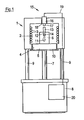
- eine teilweise geschnittene Seitenansicht eines erfindungsgemäßen Pressofens.
- Der dargestellte Pressofen umfasst ein Brennofengehäuse 1 mit einer darin vorhandenen Brennkammer 2 und einer in der Brennkammer 2 vorhandenen Heizspirale 3. An ihrer Unterseite weist die Brennkammer 2 eine Öffnung 4 auf, durch welche ein Träger 5 für eine Muffel 6 in die Brennkammer 2 ein- und aus dieser ausfahrbar ist. Zum Ein- und Ausfahren des Trägers 5 ist ein Lift 7 vorgesehen, der an der Unterseite des Trägers 5 angreift.
- Der Lift 7 ist durch einen hier nicht dargestellten, in einem unterhalb des Brennofengehäuses 1 angeordneten Sockelgehäuse 8 vorhandenen Antrieb betätigbar. Über Säulen 9 trägt das Sockelgehäuse 8 das Brennofengehäuse 1. An der Unterseite des Trägers 5 ist eine Platte 10 angeordnet, über welche die Brennkammer 2 bei eingefahrenem Träger 5 gasdicht verschließbar ist.
- Die Muffel 6 weist einen Hohlraum 11 auf, dessen Form einem gewünschten Zahnersatz oder Zahnteilersatz entspricht und zuvor mit Hilfe eines Modells in bekannter Weise hergestellt wurde. Der Hohlraum 11 ist an einen Kanal 12 angeschlossen, der auf der Oberseite der Muffel 6 mündet. Der Kanal 12 dient als Führung für einen Pressstempel 13 und zur Aufnahme eines Pellets 14 aus Zahnersatzmaterial. Oberhalb der Muffel 6 und der Brennkammeröffnung 4 gegenüberliegend ist ein Antrieb 15 für den Pressstempel 13 vorgesehen. Dieser besteht aus einem Elektromagneten 16 mit einer hier nicht dargestellten Magnetspule und einem Magnetanker 17. Der Elektromagnet ist in eine Ausnehmung 18 in der Oberseite des Brennofengehäuses 1 eingesetzt. Der Magnetanker 17 ist mit dem Pressstempel 13 axial ausgerichtet und zum Antreiben des Pressstempels 13 ausgebildet.
- Hierfür wird der Elektromagnet 16 bestromt, was über eine Zufuhrleitung 19 erfolgt, die andererseits mit einer Energieversorgungs- und Steuereinheit 20 im Sockelgehäuse 8 des Pressofens verbunden ist. Beim Bestromen des Elektromagneten 16 fährt der Magnetanker 17 aus dem Elektromagneten 16 aus und treibt den Pressstempel 13 in den Presskanal 12 der Muffel 16.
- Zur Herstellung eines Zahnersatzes oder Zahnteilersatzes mit dem dargestellten Pressofen wird eine zuvor hergestellte Muffel 6 mit Formraum 11, Presskanal 12 und einem darin angeordneten Pellet 14 aus Zahnersatzmaterial auf dem aus der Brennkammer 2 ausgefahrenen Träger 5 des Pressofens positioniert. In den Presskanal 12 der Muffel 6 wird ein Pressstempel 13 eingesetzt. Danach wird der Träger 5 mit der Muffel 6 über den Lift 7 in die Brennkammer 2 eingefahren, wobei diese durch den Teller 10 gasdicht abgedichtet wird.
- Zur Ausübung eines bestimmten Pressdrucks auf den Pressstempel 13 wird nun, nachdem die Brennkammer 2 gewünschtenfalls evakuiert, teilevakuiert und/oder mit Schutzgas geflutet und das Pellet 14 ausreichend aufgeheizt wurde, der Elektromagnet 16 derart über die Leitung 19 bestromt, dass der Magnetanker 17 auf den Pressstempel 13 einen gewünschten Druck bzw. eine gewünschte Presskraft ausübt. Diese Presskraft wird vom Pressstempel 13 auf das Zahnersatzmaterial 14 übertragen. Über die Steuereinheit 20 kann dabei ein gewünschter Presskraftverlauf über die Zeit realisiert werden. Dies kann beispielsweise dadurch geschehen, dass die Leistungsaufnahme des Elektromagneten 16 gemessen und aus der Leistungsaufnahme die ausgeübte Presskraft berechnet wird. Eine andere Möglichkeit besteht darin, aus dem Spannungsabfall am Elektromagneten 16 oder aus dessen Stromaufnahme die Position des Magnetankers 17 und damit des Pressstempels 13 zu bestimmen. Über die Position des Pressstempels 13 kann der Eindringweg berechnet werden.
- Nach beendetem Pressen wird die Brennkammer 2 gegebenenfalls belüftet. Danach kann die Brennkammer durch Herabfahren des Trägers 5 geöffnet und die Muffel 6 mit dem hergestellten Zahnersatz oder Zahnteilersatz entnommen werden.
-
- 1
- Brennkammergehäuse
- 2
- Brennkammer
- 3
- Heizeinrichtung
- 4
- untere Öffnung von 1
- 5
- Träger
- 6
- Muffel
- 7
- Lift
- 8
- Sockelgehäuse
- 9
- Säule
- 10
- Teller
- 11
- Formraum
- 12
- Presskanal
- 13
- Pressstempel
- 14
- Pellet
- 15
- Antrieb
- 16
- Elektromagnet
- 17
- Magnetanker
- 18
- Ausnehmung
- 19
- Versorgungsleitung
- 20
- Versorgungs- und Steuereinheit
Claims (7)
- Pressofen für Zahnersatz oder Zahnteilersatz mit einer Brennkammer (2), in welcher eine Pressform, insbesondere Muffel (6), mit einem Presskanal (12) zum Einführen eines Pressstempels (13) positionierbar ist, und einem Antrieb (15) zum Antreiben des Pressstempels (13),
dadurch gekennzeichnet, dass
als Antrieb (15) ein Elektromagnet (16) vorgesehen ist, dessen Magnetanker (17) oder Magnetspule den Pressstempel (13) antreibt. - Pressofen nach Anspruch 1,
dadurch gekennzeichnet, dass
der Elektromagnet (16) als Wechselstrommagnet ausgebildet ist. - Pressofen nach Anspruch 1 oder 2,
dadurch gekennzeichnet, dass
Mittel zur Messung der Leistungsaufnahme des Elektromagneten (16) sowie Mittel zur Bestimmung der auf den Pressstempel (13) ausgeübten Kraft anhand der gemessenen Leistungsaufnahme vorgesehen sind. - Pressofen nach einem der vorhergehenden Ansprüche,
dadurch gekennzeichnet, dass
Mittel zur Messung des Spannungsabfalls am Elektromagneten (16) oder der Stromaufnahme des Elektromagneten (16) sowie Mittel zur Bestimmung der Position des Magnetankers (17) oder der Magnetspule und daraus der Position des Pressstempels (13) aufgrund der gemessenen Spannung oder der gemessenen Leistungsaufnahme vorgesehen sind. - Pressofen nach einem der vorhergehenden Ansprüche,
dadurch gekennzeichnet, dass
die Brennkammer (2) zumindest teilweise evakuierbar ist. - Pressofen nach einem der vorhergehenden Ansprüche,
dadurch gekennzeichnet, dass
die Brennkammer (2) mit Schutzgas befüllbar ist. - Pressofen nach einem der vorhergehenden Ansprüche,
dadurch gekennzeichnet, dass
Mittel vorgesehen sind, durch welche eine voreingegebene Presszeit in Abhängigkeit von gemessenem Ofenparametern, insbesondere der Leistungs- oder Stromaufnahme des Elektromagneten (16) oder des Spannungsabfalls am Elektromagneten (16) in einem oder mehreren Schritten verkürzbar ist.
Applications Claiming Priority (2)
| Application Number | Priority Date | Filing Date | Title |
|---|---|---|---|
| DE201010053873 DE102010053873A1 (de) | 2010-12-09 | 2010-12-09 | Pressofen für Zahnersatz oder Zahnteilersatz |
| PCT/EP2011/006049 WO2012076134A1 (de) | 2010-12-09 | 2011-12-01 | Pressofen für zahnersatz oder zahnteilersatz |
Publications (2)
| Publication Number | Publication Date |
|---|---|
| EP2627281A1 EP2627281A1 (de) | 2013-08-21 |
| EP2627281B1 true EP2627281B1 (de) | 2014-09-03 |
Family
ID=45099017
Family Applications (1)
| Application Number | Title | Priority Date | Filing Date |
|---|---|---|---|
| EP20110791445 Active EP2627281B1 (de) | 2010-12-09 | 2011-12-01 | Pressofen für zahnersatz oder zahnteilersatz |
Country Status (4)
| Country | Link |
|---|---|
| US (1) | US9022763B2 (de) |
| EP (1) | EP2627281B1 (de) |
| DE (1) | DE102010053873A1 (de) |
| WO (1) | WO2012076134A1 (de) |
Families Citing this family (8)
| Publication number | Priority date | Publication date | Assignee | Title |
|---|---|---|---|---|
| EP2772223B1 (de) * | 2013-02-27 | 2017-10-11 | Ivoclar Vivadent AG | Dentalpressofen |
| EP2886080A1 (de) * | 2013-12-20 | 2015-06-24 | Ivoclar Vivadent AG | Verfahren zum Verarbeiten eines Dentalmaterials, Regeleinrichtung für einen Dentalofen und Dentalofen |
| US11376104B2 (en) | 2013-12-20 | 2022-07-05 | Ivoclar Vivadent Ag | Method for processing a dental material and a dental furnace |
| EP3096100B1 (de) * | 2015-05-22 | 2019-03-27 | Ivoclar Vivadent AG | Dentalpressofen |
| CN108007203B (zh) * | 2016-10-31 | 2019-11-22 | 辽宁爱尔创生物材料有限公司 | 一种快速烧结系统及快速烧结方法 |
| EP3321621A1 (de) * | 2016-11-15 | 2018-05-16 | Ivoclar Vivadent AG | Anordnung eines ofens und eines haufwerks von glaspartikeln sowie verfahren zum betriebs eines ofens |
| EP3388767B1 (de) * | 2017-04-12 | 2019-08-28 | Ivoclar Vivadent AG | Dentalbehandlungsgerät |
| CN110037816A (zh) * | 2018-01-17 | 2019-07-23 | 北京市华瑞恒美科技发展有限责任公司 | 一种义齿支架制造工艺 |
Family Cites Families (11)
| Publication number | Priority date | Publication date | Assignee | Title |
|---|---|---|---|---|
| US2228916A (en) * | 1937-05-10 | 1941-01-14 | Simons Leon | Method of making an alloy |
| US3069742A (en) * | 1956-07-21 | 1962-12-25 | Walchhuetter Ulrico | Electric and electronic circuits for controlling friction presses |
| US4273581A (en) * | 1978-04-07 | 1981-06-16 | Inoue-Japax Research Incorporated | Sintering method |
| DE3500267A1 (de) | 1985-01-05 | 1986-07-10 | Vacuumschmelze Gmbh, 6450 Hanau | Tiegel mit einer duesenartigen oeffnung zur aufnahme einer schmelze |
| DE4002358C1 (en) | 1990-01-26 | 1991-10-24 | Ivoclar Ag, Schaan, Li | Oven control for dental material pressing and hardening - detects degree of filling of shaping space by speed of movement of piston in pressure cylinder |
| JPH08281405A (ja) | 1995-04-11 | 1996-10-29 | Ohara:Kk | 鋳造装置 |
| US6612826B1 (en) * | 1997-10-15 | 2003-09-02 | Iap Research, Inc. | System for consolidating powders |
| US6303059B1 (en) | 1999-03-26 | 2001-10-16 | Ivoclar A.G. | Method of controlling an oven |
| US20020102519A1 (en) * | 2001-01-26 | 2002-08-01 | Lloyd Baum | Dental prostheses fabrication method using pre-contoured impressionable pattern |
| DE102004013668B4 (de) * | 2004-03-19 | 2008-04-10 | Ivoclar Vivadent Ag | Pressofen sowie Zwischenkörper für einen Pressofen und Verfahren für den Betrieb eines Pressofens |
| KR100656467B1 (ko) | 2006-07-26 | 2006-12-11 | 유화정 | 치과용 의치 성형기 |
-
2010
- 2010-12-09 DE DE201010053873 patent/DE102010053873A1/de not_active Withdrawn
-
2011
- 2011-12-01 US US13/992,668 patent/US9022763B2/en active Active
- 2011-12-01 WO PCT/EP2011/006049 patent/WO2012076134A1/de active Application Filing
- 2011-12-01 EP EP20110791445 patent/EP2627281B1/de active Active
Also Published As
| Publication number | Publication date |
|---|---|
| DE102010053873A1 (de) | 2012-06-14 |
| US20130302459A1 (en) | 2013-11-14 |
| WO2012076134A1 (de) | 2012-06-14 |
| US9022763B2 (en) | 2015-05-05 |
| EP2627281A1 (de) | 2013-08-21 |
Similar Documents
| Publication | Publication Date | Title |
|---|---|---|
| EP2627281B1 (de) | Pressofen für zahnersatz oder zahnteilersatz | |
| DE4002358C1 (en) | Oven control for dental material pressing and hardening - detects degree of filling of shaping space by speed of movement of piston in pressure cylinder | |
| EP3178441B1 (de) | Verfahren zum verarbeiten eines dentalmaterials, regeleinrichtung für einen dentalofen und dentalofen | |
| DE102012213279A1 (de) | Sinterofen für Bauteile aus einem Sinterwerkstoff, insbesondere für Dentalbauteile und Verfahren zur Sinterung derartiger Bauteile | |
| DE102013113892A1 (de) | Kraftstoffeinspritzventil | |
| EP2550930A1 (de) | Dentalofen | |
| EP1566231A2 (de) | Pulverpresse | |
| EP1915973B1 (de) | Verfahren zum Betrieb eines Pressofens sowie Pressofen | |
| WO2003011168A1 (de) | Verfahren zur herstellung von presskeramik in der zahntechnik; keramikpressofen, muffel und muffellehere hierfür | |
| WO2014090487A1 (de) | Dentalofen | |
| EP1618348B1 (de) | Dentaltechnikofen zur herstellung von presskeramik | |
| EP3096100B1 (de) | Dentalpressofen | |
| DE19844136B4 (de) | Ofen für die Herstellung von Zahnersatzteilen | |
| EP1901675B1 (de) | Pressofen für zahnersatz oder zahnteilersatz | |
| DE102006004433C5 (de) | Pressofen | |
| DE10327892B3 (de) | Vorrichtung zum Pressen von dentalkeramischer Masse für die Herstellung von Zahnersatz, wie Kronen, Brücken, Inlays , sowie eine Kolben-Muffelanordnung für eine solche Vorrichtung | |
| DE202007004265U1 (de) | Vorrichtung zum Pressen eines dentalen Materials zur Herstellung eines Zahnersatzes oder Zahnteilersatzes | |
| EP2772223B1 (de) | Dentalpressofen | |
| EP3321621A1 (de) | Anordnung eines ofens und eines haufwerks von glaspartikeln sowie verfahren zum betriebs eines ofens | |
| DE10324404A1 (de) | Verfahren zur Herstellung von Objekten zum Zahnersatz oder-teilersatz und Pressofen hierfür | |
| DE102005016528A1 (de) | Verfahren zur Herstellung eines hochpräzisen bolzenförmigen Elements, ein bolzenförmiges Element sowie eine Vorrichtung zur Herstellung des Elements | |
| AT233062B (de) | Verfahren und Vorrichtung zum Aufschmelzen einer oder mehrerer Elektroden auf einen Halbleiterkörper | |
| DE1142970B (de) | Verfahren und Vorrichtung zum Aufschmelzen von Elektroden auf einen Halbleiterkoerper | |
| DE202017001371U1 (de) | Vorrichtung zur Herstellung von Presskeramik in der Dentaltechnik | |
| DE1452880B2 (de) | Biegemaschine fuer bleche, profile und dergl |
Legal Events
| Date | Code | Title | Description |
|---|---|---|---|
| PUAI | Public reference made under article 153(3) epc to a published international application that has entered the european phase |
Free format text: ORIGINAL CODE: 0009012 |
|
| 17P | Request for examination filed |
Effective date: 20130516 |
|
| AK | Designated contracting states |
Kind code of ref document: A1 Designated state(s): AL AT BE BG CH CY CZ DE DK EE ES FI FR GB GR HR HU IE IS IT LI LT LU LV MC MK MT NL NO PL PT RO RS SE SI SK SM TR |
|
| DAX | Request for extension of the european patent (deleted) | ||
| GRAP | Despatch of communication of intention to grant a patent |
Free format text: ORIGINAL CODE: EPIDOSNIGR1 |
|
| INTG | Intention to grant announced |
Effective date: 20140313 |
|
| GRAS | Grant fee paid |
Free format text: ORIGINAL CODE: EPIDOSNIGR3 |
|
| GRAA | (expected) grant |
Free format text: ORIGINAL CODE: 0009210 |
|
| AK | Designated contracting states |
Kind code of ref document: B1 Designated state(s): AL AT BE BG CH CY CZ DE DK EE ES FI FR GB GR HR HU IE IS IT LI LT LU LV MC MK MT NL NO PL PT RO RS SE SI SK SM TR |
|
| REG | Reference to a national code |
Ref country code: GB Ref legal event code: FG4D Free format text: NOT ENGLISH |
|
| REG | Reference to a national code |
Ref country code: CH Ref legal event code: EP Ref country code: AT Ref legal event code: REF Ref document number: 685144 Country of ref document: AT Kind code of ref document: T Effective date: 20140915 |
|
| REG | Reference to a national code |
Ref country code: IE Ref legal event code: FG4D Free format text: LANGUAGE OF EP DOCUMENT: GERMAN |
|
| REG | Reference to a national code |
Ref country code: DE Ref legal event code: R096 Ref document number: 502011004294 Country of ref document: DE Effective date: 20141016 |
|
| PG25 | Lapsed in a contracting state [announced via postgrant information from national office to epo] |
Ref country code: ES Free format text: LAPSE BECAUSE OF FAILURE TO SUBMIT A TRANSLATION OF THE DESCRIPTION OR TO PAY THE FEE WITHIN THE PRESCRIBED TIME-LIMIT Effective date: 20140903 Ref country code: NO Free format text: LAPSE BECAUSE OF FAILURE TO SUBMIT A TRANSLATION OF THE DESCRIPTION OR TO PAY THE FEE WITHIN THE PRESCRIBED TIME-LIMIT Effective date: 20141203 Ref country code: SE Free format text: LAPSE BECAUSE OF FAILURE TO SUBMIT A TRANSLATION OF THE DESCRIPTION OR TO PAY THE FEE WITHIN THE PRESCRIBED TIME-LIMIT Effective date: 20140903 Ref country code: GR Free format text: LAPSE BECAUSE OF FAILURE TO SUBMIT A TRANSLATION OF THE DESCRIPTION OR TO PAY THE FEE WITHIN THE PRESCRIBED TIME-LIMIT Effective date: 20141204 Ref country code: FI Free format text: LAPSE BECAUSE OF FAILURE TO SUBMIT A TRANSLATION OF THE DESCRIPTION OR TO PAY THE FEE WITHIN THE PRESCRIBED TIME-LIMIT Effective date: 20140903 Ref country code: LT Free format text: LAPSE BECAUSE OF FAILURE TO SUBMIT A TRANSLATION OF THE DESCRIPTION OR TO PAY THE FEE WITHIN THE PRESCRIBED TIME-LIMIT Effective date: 20140903 |
|
| REG | Reference to a national code |
Ref country code: NL Ref legal event code: VDEP Effective date: 20140903 |
|
| REG | Reference to a national code |
Ref country code: LT Ref legal event code: MG4D |
|
| PG25 | Lapsed in a contracting state [announced via postgrant information from national office to epo] |
Ref country code: HR Free format text: LAPSE BECAUSE OF FAILURE TO SUBMIT A TRANSLATION OF THE DESCRIPTION OR TO PAY THE FEE WITHIN THE PRESCRIBED TIME-LIMIT Effective date: 20140903 Ref country code: RS Free format text: LAPSE BECAUSE OF FAILURE TO SUBMIT A TRANSLATION OF THE DESCRIPTION OR TO PAY THE FEE WITHIN THE PRESCRIBED TIME-LIMIT Effective date: 20140903 Ref country code: LV Free format text: LAPSE BECAUSE OF FAILURE TO SUBMIT A TRANSLATION OF THE DESCRIPTION OR TO PAY THE FEE WITHIN THE PRESCRIBED TIME-LIMIT Effective date: 20140903 Ref country code: CY Free format text: LAPSE BECAUSE OF FAILURE TO SUBMIT A TRANSLATION OF THE DESCRIPTION OR TO PAY THE FEE WITHIN THE PRESCRIBED TIME-LIMIT Effective date: 20140903 |
|
| PG25 | Lapsed in a contracting state [announced via postgrant information from national office to epo] |
Ref country code: NL Free format text: LAPSE BECAUSE OF FAILURE TO SUBMIT A TRANSLATION OF THE DESCRIPTION OR TO PAY THE FEE WITHIN THE PRESCRIBED TIME-LIMIT Effective date: 20140903 |
|
| PG25 | Lapsed in a contracting state [announced via postgrant information from national office to epo] |
Ref country code: PT Free format text: LAPSE BECAUSE OF FAILURE TO SUBMIT A TRANSLATION OF THE DESCRIPTION OR TO PAY THE FEE WITHIN THE PRESCRIBED TIME-LIMIT Effective date: 20150105 Ref country code: IS Free format text: LAPSE BECAUSE OF FAILURE TO SUBMIT A TRANSLATION OF THE DESCRIPTION OR TO PAY THE FEE WITHIN THE PRESCRIBED TIME-LIMIT Effective date: 20150103 Ref country code: CZ Free format text: LAPSE BECAUSE OF FAILURE TO SUBMIT A TRANSLATION OF THE DESCRIPTION OR TO PAY THE FEE WITHIN THE PRESCRIBED TIME-LIMIT Effective date: 20140903 Ref country code: RO Free format text: LAPSE BECAUSE OF FAILURE TO SUBMIT A TRANSLATION OF THE DESCRIPTION OR TO PAY THE FEE WITHIN THE PRESCRIBED TIME-LIMIT Effective date: 20140903 Ref country code: SK Free format text: LAPSE BECAUSE OF FAILURE TO SUBMIT A TRANSLATION OF THE DESCRIPTION OR TO PAY THE FEE WITHIN THE PRESCRIBED TIME-LIMIT Effective date: 20140903 Ref country code: EE Free format text: LAPSE BECAUSE OF FAILURE TO SUBMIT A TRANSLATION OF THE DESCRIPTION OR TO PAY THE FEE WITHIN THE PRESCRIBED TIME-LIMIT Effective date: 20140903 |
|
| PG25 | Lapsed in a contracting state [announced via postgrant information from national office to epo] |
Ref country code: PL Free format text: LAPSE BECAUSE OF FAILURE TO SUBMIT A TRANSLATION OF THE DESCRIPTION OR TO PAY THE FEE WITHIN THE PRESCRIBED TIME-LIMIT Effective date: 20140903 |
|
| REG | Reference to a national code |
Ref country code: DE Ref legal event code: R097 Ref document number: 502011004294 Country of ref document: DE |
|
| PG25 | Lapsed in a contracting state [announced via postgrant information from national office to epo] |
Ref country code: BE Free format text: LAPSE BECAUSE OF NON-PAYMENT OF DUE FEES Effective date: 20141231 |
|
| PLBE | No opposition filed within time limit |
Free format text: ORIGINAL CODE: 0009261 |
|
| STAA | Information on the status of an ep patent application or granted ep patent |
Free format text: STATUS: NO OPPOSITION FILED WITHIN TIME LIMIT |
|
| PG25 | Lapsed in a contracting state [announced via postgrant information from national office to epo] |
Ref country code: LU Free format text: LAPSE BECAUSE OF FAILURE TO SUBMIT A TRANSLATION OF THE DESCRIPTION OR TO PAY THE FEE WITHIN THE PRESCRIBED TIME-LIMIT Effective date: 20141201 Ref country code: DK Free format text: LAPSE BECAUSE OF FAILURE TO SUBMIT A TRANSLATION OF THE DESCRIPTION OR TO PAY THE FEE WITHIN THE PRESCRIBED TIME-LIMIT Effective date: 20140903 |
|
| REG | Reference to a national code |
Ref country code: CH Ref legal event code: PL |
|
| 26N | No opposition filed |
Effective date: 20150604 |
|
| REG | Reference to a national code |
Ref country code: IE Ref legal event code: MM4A |
|
| PG25 | Lapsed in a contracting state [announced via postgrant information from national office to epo] |
Ref country code: IE Free format text: LAPSE BECAUSE OF NON-PAYMENT OF DUE FEES Effective date: 20141201 Ref country code: LI Free format text: LAPSE BECAUSE OF NON-PAYMENT OF DUE FEES Effective date: 20141231 Ref country code: CH Free format text: LAPSE BECAUSE OF NON-PAYMENT OF DUE FEES Effective date: 20141231 |
|
| PG25 | Lapsed in a contracting state [announced via postgrant information from national office to epo] |
Ref country code: SI Free format text: LAPSE BECAUSE OF FAILURE TO SUBMIT A TRANSLATION OF THE DESCRIPTION OR TO PAY THE FEE WITHIN THE PRESCRIBED TIME-LIMIT Effective date: 20140903 |
|
| REG | Reference to a national code |
Ref country code: FR Ref legal event code: PLFP Year of fee payment: 5 |
|
| PG25 | Lapsed in a contracting state [announced via postgrant information from national office to epo] |
Ref country code: SM Free format text: LAPSE BECAUSE OF FAILURE TO SUBMIT A TRANSLATION OF THE DESCRIPTION OR TO PAY THE FEE WITHIN THE PRESCRIBED TIME-LIMIT Effective date: 20140903 |
|
| PG25 | Lapsed in a contracting state [announced via postgrant information from national office to epo] |
Ref country code: MC Free format text: LAPSE BECAUSE OF FAILURE TO SUBMIT A TRANSLATION OF THE DESCRIPTION OR TO PAY THE FEE WITHIN THE PRESCRIBED TIME-LIMIT Effective date: 20140903 |
|
| PG25 | Lapsed in a contracting state [announced via postgrant information from national office to epo] |
Ref country code: BG Free format text: LAPSE BECAUSE OF FAILURE TO SUBMIT A TRANSLATION OF THE DESCRIPTION OR TO PAY THE FEE WITHIN THE PRESCRIBED TIME-LIMIT Effective date: 20140903 |
|
| PG25 | Lapsed in a contracting state [announced via postgrant information from national office to epo] |
Ref country code: TR Free format text: LAPSE BECAUSE OF FAILURE TO SUBMIT A TRANSLATION OF THE DESCRIPTION OR TO PAY THE FEE WITHIN THE PRESCRIBED TIME-LIMIT Effective date: 20140903 Ref country code: MT Free format text: LAPSE BECAUSE OF FAILURE TO SUBMIT A TRANSLATION OF THE DESCRIPTION OR TO PAY THE FEE WITHIN THE PRESCRIBED TIME-LIMIT Effective date: 20140903 Ref country code: HU Free format text: LAPSE BECAUSE OF FAILURE TO SUBMIT A TRANSLATION OF THE DESCRIPTION OR TO PAY THE FEE WITHIN THE PRESCRIBED TIME-LIMIT; INVALID AB INITIO Effective date: 20111201 |
|
| REG | Reference to a national code |
Ref country code: FR Ref legal event code: PLFP Year of fee payment: 6 |
|
| REG | Reference to a national code |
Ref country code: FR Ref legal event code: PLFP Year of fee payment: 7 |
|
| REG | Reference to a national code |
Ref country code: AT Ref legal event code: MM01 Ref document number: 685144 Country of ref document: AT Kind code of ref document: T Effective date: 20161201 |
|
| PG25 | Lapsed in a contracting state [announced via postgrant information from national office to epo] |
Ref country code: AT Free format text: LAPSE BECAUSE OF NON-PAYMENT OF DUE FEES Effective date: 20161201 |
|
| PG25 | Lapsed in a contracting state [announced via postgrant information from national office to epo] |
Ref country code: MK Free format text: LAPSE BECAUSE OF FAILURE TO SUBMIT A TRANSLATION OF THE DESCRIPTION OR TO PAY THE FEE WITHIN THE PRESCRIBED TIME-LIMIT Effective date: 20140903 |
|
| PG25 | Lapsed in a contracting state [announced via postgrant information from national office to epo] |
Ref country code: AL Free format text: LAPSE BECAUSE OF FAILURE TO SUBMIT A TRANSLATION OF THE DESCRIPTION OR TO PAY THE FEE WITHIN THE PRESCRIBED TIME-LIMIT Effective date: 20140903 |
|
| PGFP | Annual fee paid to national office [announced via postgrant information from national office to epo] |
Ref country code: GB Payment date: 20231220 Year of fee payment: 13 |
|
| PGFP | Annual fee paid to national office [announced via postgrant information from national office to epo] |
Ref country code: IT Payment date: 20231228 Year of fee payment: 13 Ref country code: FR Payment date: 20231221 Year of fee payment: 13 |
|
| PGFP | Annual fee paid to national office [announced via postgrant information from national office to epo] |
Ref country code: DE Payment date: 20240227 Year of fee payment: 13 |