EP2626941A1 - Fuel cell generation system - Google Patents
Fuel cell generation system Download PDFInfo
- Publication number
- EP2626941A1 EP2626941A1 EP13154376.1A EP13154376A EP2626941A1 EP 2626941 A1 EP2626941 A1 EP 2626941A1 EP 13154376 A EP13154376 A EP 13154376A EP 2626941 A1 EP2626941 A1 EP 2626941A1
- Authority
- EP
- European Patent Office
- Prior art keywords
- module
- heat
- fuel cell
- lhp
- fluid
- Prior art date
- Legal status (The legal status is an assumption and is not a legal conclusion. Google has not performed a legal analysis and makes no representation as to the accuracy of the status listed.)
- Granted
Links
Images


Classifications
-
- H—ELECTRICITY
- H01—ELECTRIC ELEMENTS
- H01M—PROCESSES OR MEANS, e.g. BATTERIES, FOR THE DIRECT CONVERSION OF CHEMICAL ENERGY INTO ELECTRICAL ENERGY
- H01M8/00—Fuel cells; Manufacture thereof
- H01M8/04—Auxiliary arrangements, e.g. for control of pressure or for circulation of fluids
- H01M8/04007—Auxiliary arrangements, e.g. for control of pressure or for circulation of fluids related to heat exchange
- H01M8/04067—Heat exchange or temperature measuring elements, thermal insulation, e.g. heat pipes, heat pumps, fins
- H01M8/04074—Heat exchange unit structures specially adapted for fuel cell
-
- H—ELECTRICITY
- H01—ELECTRIC ELEMENTS
- H01M—PROCESSES OR MEANS, e.g. BATTERIES, FOR THE DIRECT CONVERSION OF CHEMICAL ENERGY INTO ELECTRICAL ENERGY
- H01M2250/00—Fuel cells for particular applications; Specific features of fuel cell system
- H01M2250/20—Fuel cells in motive systems, e.g. vehicle, ship, plane
-
- Y—GENERAL TAGGING OF NEW TECHNOLOGICAL DEVELOPMENTS; GENERAL TAGGING OF CROSS-SECTIONAL TECHNOLOGIES SPANNING OVER SEVERAL SECTIONS OF THE IPC; TECHNICAL SUBJECTS COVERED BY FORMER USPC CROSS-REFERENCE ART COLLECTIONS [XRACs] AND DIGESTS
- Y02—TECHNOLOGIES OR APPLICATIONS FOR MITIGATION OR ADAPTATION AGAINST CLIMATE CHANGE
- Y02E—REDUCTION OF GREENHOUSE GAS [GHG] EMISSIONS, RELATED TO ENERGY GENERATION, TRANSMISSION OR DISTRIBUTION
- Y02E60/00—Enabling technologies; Technologies with a potential or indirect contribution to GHG emissions mitigation
- Y02E60/30—Hydrogen technology
- Y02E60/50—Fuel cells
-
- Y—GENERAL TAGGING OF NEW TECHNOLOGICAL DEVELOPMENTS; GENERAL TAGGING OF CROSS-SECTIONAL TECHNOLOGIES SPANNING OVER SEVERAL SECTIONS OF THE IPC; TECHNICAL SUBJECTS COVERED BY FORMER USPC CROSS-REFERENCE ART COLLECTIONS [XRACs] AND DIGESTS
- Y02—TECHNOLOGIES OR APPLICATIONS FOR MITIGATION OR ADAPTATION AGAINST CLIMATE CHANGE
- Y02T—CLIMATE CHANGE MITIGATION TECHNOLOGIES RELATED TO TRANSPORTATION
- Y02T90/00—Enabling technologies or technologies with a potential or indirect contribution to GHG emissions mitigation
- Y02T90/40—Application of hydrogen technology to transportation, e.g. using fuel cells
Definitions
- the present disclosure relates generally to heat transfer systems and, more particularly, to methods and systems for transferring heat produced by a fuel cell module positioned onboard an aircraft.
- Known aircraft include a plurality of engines that generate lifting power. At least some known aircraft include electrical components that require electricity to operate. To provide electricity to such electrical components, at least some known aircraft extract power from the engines. However, supplying electricity from the engines to the electrical components increases an overall fuel consumption of the engine. To facilitate reducing electrical demand from the engines, at least some known aircraft include fuel cells that generate power for use in powering onboard electrical components. However, at least some known aircraft do not efficiently utilize electricity and/or byproducts generated by the fuel cell.
- a method for transferring heat produced by a fuel cell module positioned onboard an aircraft.
- the method includes coupling a loop heat pipe (LHP) module to the fuel cell module.
- the LHP module includes a first fluid that absorbs the heat from the fuel cell module and is channeled through the LHP module.
- a power generation system for use on an aircraft.
- the power generation system includes a fuel cell module configured to produce heat and a LHP module coupled to the fuel cell module.
- the LHP module includes a first fluid that absorbs the heat from the fuel cell module and is channeled through the LHP module.
- a system in yet another aspect, includes an aircraft and an electronic device positioned onboard the aircraft.
- a fuel cell module is coupled to the electronic device.
- the fuel cell module is configured to produce electricity and heat.
- the electricity is transmitted to the electronic device.
- a LHP module is coupled to the fuel cell module.
- the LHP module includes a first fluid that absorbs the heat from the fuel cell module and is channeled through the LHP module.
- a method of transferring heat produced by a fuel cell module positioned onboard an aircraft comprising coupling a loop heat pipe (LHP) module to the fuel cell module, the LHP module including a first fluid and channeling the first fluid through the LHP module, wherein the first fluid absorbs the heat from the fuel cell module.
- the method may further comprise transferring the heat to an external load.
- the method may further comprise coupling a heat transfer module to the LHP module, the heat transfer module including a second fluid and channeling the second fluid through the heat transfer module, wherein the second fluid absorbs the heat from the LHP module.
- the step of channeling the second fluid further comprises selectively pumping the second fluid through the heat transfer module.
- a power generation system for use on an aircraft, said power generation system comprising a fuel cell module configured to produce heat and a loop heat pipe (LHP) module coupled to said fuel cell module, said LHP module comprising a first fluid that absorbs the heat from said fuel cell module and is channeled through said LHP module.
- the system may further comprise an external load coupled to said LHP module, wherein the heat is transferred to said external load.
- the LHP module may further comprise a heat spreader that facilitates transferring the heat to an external load.
- the system may further comprise a heat transfer module coupled to the LHP module, said heat transfer module comprising a second fluid that absorbs the heat from said LHP module and is channeled through the heat transfer module.
- the heat transfer module further comprises a pump configured to selectively channel the second fluid through said heat transfer module.
- the heat transfer module further comprises a radiator.
- the system may further comprise a fluid transfer module comprising a water purifier coupled to said fuel cell module, the fuel cell module configured to discharge water through said fluid transfer module.
- a system comprising an aircraft, an electronic device positioned onboard said aircraft, a fuel cell module coupled to said electronic device, said fuel cell module configured to produce electricity and heat, wherein the electricity is transmitted to said electronic device, and a loop heat pipe (LHP) module coupled to said fuel cell module, said LHP module comprising a first fluid that absorbs the heat from said fuel cell module and is channeled through said LHP module.
- the system may further comprise an external load coupled to said LHP module, wherein the heat is transferred to said external load.
- the LHP module comprises a heat spreader that facilitates transferring the heat to an external load.
- the system may further comprise a heat transfer module coupled to said LHP module, said heat transfer module comprising a second fluid that absorbs the heat from said LHP module and is channeled through the heat transfer module.
- the heat transfer module further comprises a pump configured to selectively channel the second fluid through said heat transfer module.
- the heat transfer module further comprises a radiator.
- the system may further comprise a fluid transfer module comprising a water purifier coupled to said fuel cell module, said fuel cell module configured to discharge water through said fluid transfer module.
- a power generation system onboard an aircraft includes a fuel cell module configured to produce heat and electricity.
- a loop heat pipe (LHP) module is coupled to the fuel cell module.
- the LHP module includes a first fluid (i.e., a working fluid) that absorbs the heat from the fuel cell module and is channeled through the LHP module. As such, the LHP module facilitates cooling the fuel cell module.
- the term "load” or “external load” refers to any device and/or machine that utilizes electricity, heat, water, and/or any other byproduct generated, created, and/or produced by another device and/or machine.
- An element or step recited in the singular and proceeded with the word “a” or “an” should be understood as not excluding plural elements or steps unless such exclusion is explicitly recited.
- an element or step recited in the singular and proceeded with the word “a” or “an” should be understood as not excluding plural elements or steps unless such exclusion is explicitly recited.
- references to "one embodiment" of the present invention and/or the "exemplary embodiment” are not intended to be interpreted as excluding the existence of additional embodiments that also incorporate the recited features.
- FIG. 1 is a plan view of an exemplary aircraft 100.
- aircraft 100 includes a body 110 that includes a fuselage 120 and a pair of wings 130 extending from fuselage 120.
- at least one engine 140 is coupled to each wing 130 to provide thrust to aircraft 100.
- Aircraft 100 may include any number of engines 140 that enables aircraft 100 to function as described herein.
- aircraft 100 includes at least one component and/or structure that is fabricated from a composite material.
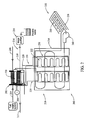
- FIG. 2 is a schematic illustration of an exemplary fuel cell cogeneration system 200 that may be used onboard aircraft 100 (shown in FIG. 1 ).
- system 200 integrates electric, heat, and water systems into a single system.
- system 200 includes a fuel cell module 202 that converts fuel 204 and air 206 into electricity 208 that may be used within aircraft 100.
- byproducts of fuel cell module 202 include water 210, air 212, and thermal energy or heat (not shown).
- system 200 includes a conduit 214 that is in flow communication with fuel cell module 202, and a water purifier 216 that is coupled to conduit 214.
- water purifier 216 facilitates increasing a drinking quality of water 210 channeled therethrough such that water 210 may be potable.
- system 200 includes a heat transfer module or loop heat pipe (LHP) module 218.
- LHP module 218 includes an evaporator 220, a condenser 222, and a heat transfer loop 224.
- evaporator 220 includes a fine pore wick structure for capillary pumping of the fluid and circulation inside LHP module 218.
- evaporator 220 is coupled directly to fuel cell module 202 to absorb heat generated by fuel cell module 202.
- evaporator 220 may have any configuration and/or be coupled to any device and/or element that enables system 200 to function as described herein.
- heat transfer loop 224 includes a vapor line 226 that channels vapor from evaporator 220 towards condenser 222, and a liquid line 228 that channels liquid from condenser 222 towards evaporator 220.
- LHP module 218 is a two-phase heat transfer device that uses capillary action to remove heat from fuel cell module 202 and passively transfer the heat to condenser 222.
- a load 230 is coupled to condenser 222 such that the heat may be used onboard aircraft 100.
- load 230 may be an appliance including, but not limited to, a coffee maker, a hot water faucet, and/or an oven.
- load 230 may be any other appliance and/or device that enables system 200 to function as described herein.
- a second heat transfer module 232 is coupled to LHP module 218.
- second heat transfer module 232 includes a heat spreader 234, a radiator 236, and a fluid line 238 extending therebetween.
- heat spreader 234 is configured to absorb heat from condenser 222 and transfer the heat to fluid channeled through fluid line 238.
- second heat transfer module 232 includes a pump 240 such that fluid is actively channeled through fluid line 238.
- second heat transfer system 232 may be a passive system such that heat is passively transferred between heat spreader 234 and radiator 236.
- radiator 236 is positioned such that heat may be transferred to the ambient environment.
- fuel cell module 202 receives fuel 204 and air 206 and generates and/or produces electricity 208, water 210, air 212, and/or heat.
- water 210 is channeled through conduit 214, and water purifier 216 makes water 210 potable.
- evaporator 220 absorbs heat from fuel cell module 202 as fluid is channeled through heat transfer loop 224. More specifically, in the exemplary embodiment, liquid channeled through evaporator 220 absorbs heat from fuel cell module 202 to enable the liquid to change into a vapor. That is, in the exemplary embodiment, heat absorbed at evaporator 220 enables the liquid to convert into vapor through a phase-change process. In the exemplary embodiment, the vapor is discharged from evaporator 220 and channeled through vapor line 226 towards condenser 222. As such, in the exemplary embodiment, heat is transported to condenser 222.
- heat is transferred from condenser 222 towards load 230 and/or heat spreader 234 to enable the vapor to change into a liquid. That is, in the exemplary embodiment, the phase-change process takes place after the vapor gives out its latent heat.
- the liquid is discharged from condenser 222 and channeled through liquid line 228 towards evaporator 220.
- second heat transfer module 232 is selectively operated to transfer heat from LHP module 218 into the ambient environment. That is, in the exemplary embodiment, pump 240 is not activated when the heat is being used by load 230, and is activated when the heat is not being used by load 230.
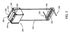
- FIG. 3 is a perspective view of fuel cell module 202 and LHP module 218.
- LHP module 218 includes a heat spreader 242 coupled directly to fuel cell module 202, and heat pipes 244 coupled to heat spreader 242 and evaporator 220.
- heat spreader 242 and/or heat pipes 244 increase the heat transfer rate between fuel cell module 202 and LHP module 218. As such, heat may be transferred from fuel cell module 202 to evaporator 220 for capillary pumping.
- heat spreader 242 and/or heat pipes 244 include wire wick and/or sintered wick.
- heat spreader 242 and/or heat pipes 244 may have any configuration and/or be fabricated from any material that enables system 200 to function as described herein.
- condenser 222 is positioned within a container 246 configured to channel water therethrough. More specifically, in the exemplary embodiment, container 246 includes an inlet 248 configured to receive water, and an outlet 250 configured to discharge water. In the exemplary embodiment, water is channeled through container 246 to facilitate cooling condenser 222 and/or fluid channeled through LHP module 218.
- FIGS. 4-6 are schematic illustrations of other fuel cell cogeneration systems 400, 500, and 600 that may be used onboard aircraft 100.
- System 400 is generally similar to system 200, but, instead of LHP module 218 being coupled directly to fuel cell module 202, LHP module 218 is coupled directly to conduit 214 to facilitate absorbing, using, and/or dissipating heat generated by fuel cell module 202.
- System 500 is generally similar to system 200, but, instead of LHP module 218, a liquid-to-liquid heat exchanger 502 is coupled to conduit 214 to facilitate absorbing, using, and/or dissipating heat generated by fuel cell module 202.
- heat exchanger 502 includes a conduit 504 extending therethrough that channels cold water into heat exchanger 502, wherein the water absorbs heat from conduit 214 and/or water 210 within conduit 214 such that hot water may be discharged from heat exchanger 502 through conduit 504.
- System 600 is generally similar to system 200, but, instead of LHP module 218, a liquid-to-air heat exchanger 602 is coupled to conduit 214 to facilitate absorbing, using, and/or dissipating heat generated by fuel cell module 202.
- heat exchanger 602 includes a conduit 604 extending therethrough that channels cold air into heat exchanger 602, wherein the air absorbs heat from conduit 214 and/or water 210 within conduit 214 such that hot air may be discharged from heat exchanger 602 through conduit 604.
- the embodiments described herein relate generally to heat transfer systems and, more particularly, to methods and systems for transferring heat produced by a fuel cell module positioned onboard an aircraft.
- the embodiments described herein facilitate increasing fuel cell efficiency for use in an airplane galley and/or decreasing a quantity of airplane generated power required to operate the airplane during flight.
- the embodiments described herein facilitate decreasing an amount of power used by galleys through energy storage, use of combined heat and power from fuel cells, and efficient transfer of the heat from the fuel cell to galley insert loads.
Abstract
Description
- The present disclosure relates generally to heat transfer systems and, more particularly, to methods and systems for transferring heat produced by a fuel cell module positioned onboard an aircraft.
- Known aircraft include a plurality of engines that generate lifting power. At least some known aircraft include electrical components that require electricity to operate. To provide electricity to such electrical components, at least some known aircraft extract power from the engines. However, supplying electricity from the engines to the electrical components increases an overall fuel consumption of the engine. To facilitate reducing electrical demand from the engines, at least some known aircraft include fuel cells that generate power for use in powering onboard electrical components. However, at least some known aircraft do not efficiently utilize electricity and/or byproducts generated by the fuel cell.
- In one aspect, a method is provided for transferring heat produced by a fuel cell module positioned onboard an aircraft. The method includes coupling a loop heat pipe (LHP) module to the fuel cell module. The LHP module includes a first fluid that absorbs the heat from the fuel cell module and is channeled through the LHP module.
- In another aspect, a power generation system is provided for use on an aircraft. The power generation system includes a fuel cell module configured to produce heat and a LHP module coupled to the fuel cell module. The LHP module includes a first fluid that absorbs the heat from the fuel cell module and is channeled through the LHP module.
- In yet another aspect, a system is provided. The system includes an aircraft and an electronic device positioned onboard the aircraft. A fuel cell module is coupled to the electronic device. The fuel cell module is configured to produce electricity and heat. The electricity is transmitted to the electronic device. A LHP module is coupled to the fuel cell module. The LHP module includes a first fluid that absorbs the heat from the fuel cell module and is channeled through the LHP module.
- According to a further aspect of the present invention there is provided a method of transferring heat produced by a fuel cell module positioned onboard an aircraft comprising coupling a loop heat pipe (LHP) module to the fuel cell module, the LHP module including a first fluid and channeling the first fluid through the LHP module, wherein the first fluid absorbs the heat from the fuel cell module. Advantageously the method may further comprise transferring the heat to an external load. Advantageously the method may further comprise coupling a heat transfer module to the LHP module, the heat transfer module including a second fluid and channeling the second fluid through the heat transfer module, wherein the second fluid absorbs the heat from the LHP module. Preferably the step of channeling the second fluid further comprises selectively pumping the second fluid through the heat transfer module.
- According to a further aspect of the present invention there is provided a power generation system for use on an aircraft, said power generation system comprising a fuel cell module configured to produce heat and a loop heat pipe (LHP) module coupled to said fuel cell module, said LHP module comprising a first fluid that absorbs the heat from said fuel cell module and is channeled through said LHP module. Advantageously the system may further comprise an external load coupled to said LHP module, wherein the heat is transferred to said external load. Advantageously the LHP module may further comprise a heat spreader that facilitates transferring the heat to an external load. Advantageously the system may further comprise a heat transfer module coupled to the LHP module, said heat transfer module comprising a second fluid that absorbs the heat from said LHP module and is channeled through the heat transfer module. Preferably the heat transfer module further comprises a pump configured to selectively channel the second fluid through said heat transfer module. Preferably the heat transfer module further comprises a radiator. Advantageously the system may further comprise a fluid transfer module comprising a water purifier coupled to said fuel cell module, the fuel cell module configured to discharge water through said fluid transfer module.
- According to a further aspect of the present invention there is provided a system comprising an aircraft, an electronic device positioned onboard said aircraft, a fuel cell module coupled to said electronic device, said fuel cell module configured to produce electricity and heat, wherein the electricity is transmitted to said electronic device, and a loop heat pipe (LHP) module coupled to said fuel cell module, said LHP module comprising a first fluid that absorbs the heat from said fuel cell module and is channeled through said LHP module. Advantageously the system may further comprise an external load coupled to said LHP module, wherein the heat is transferred to said external load. Preferably the LHP module comprises a heat spreader that facilitates transferring the heat to an external load. Advantageously the system may further comprise a heat transfer module coupled to said LHP module, said heat transfer module comprising a second fluid that absorbs the heat from said LHP module and is channeled through the heat transfer module. Preferably the heat transfer module further comprises a pump configured to selectively channel the second fluid through said heat transfer module. Preferably the heat transfer module further comprises a radiator. Advantageously the system may further comprise a fluid transfer module comprising a water purifier coupled to said fuel cell module, said fuel cell module configured to discharge water through said fluid transfer module.
- The features, functions, and advantages described herein may be achieved independently in various embodiments of the present disclosure or may be combined in yet other embodiments, further details of which may be seen with reference to the following description and drawings.
-
-
FIG. 1 is a plan view of an exemplary aircraft; -
FIG. 2 is a schematic illustration of an exemplary fuel cell cogeneration system that may be used onboard the aircraft shown inFIG. 1 ; -
FIG. 3 is a perspective view of an exemplary heat transfer system that may be used with the fuel cell cogeneration system shown inFIG. 2 ; -
FIGS. 4-6 are schematic illustrations of other fuel cell cogeneration systems that may be used onboard the aircraft shown inFIG. 1 . - Although specific features of various embodiments may be shown in some drawings and not in others, this is for convenience only. Any feature of any drawing may be referenced and/or claimed in combination with any feature of any other drawing.
- The subject matter described herein relates generally to heat transfer systems and, more particularly, to methods and systems for transferring heat produced by a fuel cell module positioned onboard an aircraft. In one embodiment, a power generation system onboard an aircraft includes a fuel cell module configured to produce heat and electricity. A loop heat pipe (LHP) module is coupled to the fuel cell module. The LHP module includes a first fluid (i.e., a working fluid) that absorbs the heat from the fuel cell module and is channeled through the LHP module. As such, the LHP module facilitates cooling the fuel cell module.
- As used herein, the term "load" or "external load" refers to any device and/or machine that utilizes electricity, heat, water, and/or any other byproduct generated, created, and/or produced by another device and/or machine. An element or step recited in the singular and proceeded with the word "a" or "an" should be understood as not excluding plural elements or steps unless such exclusion is explicitly recited. Moreover, an element or step recited in the singular and proceeded with the word "a" or "an" should be understood as not excluding plural elements or steps unless such exclusion is explicitly recited. Moreover, references to "one embodiment" of the present invention and/or the "exemplary embodiment" are not intended to be interpreted as excluding the existence of additional embodiments that also incorporate the recited features.
-
FIG. 1 is a plan view of anexemplary aircraft 100. In the exemplary embodiment,aircraft 100 includes abody 110 that includes afuselage 120 and a pair ofwings 130 extending fromfuselage 120. In the exemplary embodiment, at least oneengine 140 is coupled to eachwing 130 to provide thrust toaircraft 100.Aircraft 100 may include any number ofengines 140 that enablesaircraft 100 to function as described herein. In the exemplary embodiment,aircraft 100 includes at least one component and/or structure that is fabricated from a composite material. -
FIG. 2 is a schematic illustration of an exemplary fuelcell cogeneration system 200 that may be used onboard aircraft 100 (shown inFIG. 1 ). In the exemplary embodiment,system 200 integrates electric, heat, and water systems into a single system. In the exemplary embodiment,system 200 includes afuel cell module 202 that convertsfuel 204 andair 206 intoelectricity 208 that may be used withinaircraft 100. In the exemplary embodiment, byproducts offuel cell module 202 includewater 210,air 212, and thermal energy or heat (not shown). In the exemplary embodiment,system 200 includes aconduit 214 that is in flow communication withfuel cell module 202, and awater purifier 216 that is coupled toconduit 214. In the exemplary embodiment,water purifier 216 facilitates increasing a drinking quality ofwater 210 channeled therethrough such thatwater 210 may be potable. - In the exemplary embodiment,
system 200 includes a heat transfer module or loop heat pipe (LHP)module 218. In the exemplary embodiment,LHP module 218 includes anevaporator 220, acondenser 222, and aheat transfer loop 224. In the exemplary embodiment,evaporator 220 includes a fine pore wick structure for capillary pumping of the fluid and circulation insideLHP module 218. In the exemplary embodiment,evaporator 220 is coupled directly tofuel cell module 202 to absorb heat generated byfuel cell module 202. Alternatively,evaporator 220 may have any configuration and/or be coupled to any device and/or element that enablessystem 200 to function as described herein. - In the exemplary embodiment,
heat transfer loop 224 includes avapor line 226 that channels vapor fromevaporator 220 towardscondenser 222, and aliquid line 228 that channels liquid fromcondenser 222 towardsevaporator 220. That is, in the exemplary embodiment,LHP module 218 is a two-phase heat transfer device that uses capillary action to remove heat fromfuel cell module 202 and passively transfer the heat tocondenser 222. - In the exemplary embodiment, a
load 230 is coupled tocondenser 222 such that the heat may be usedonboard aircraft 100. For example, load 230 may be an appliance including, but not limited to, a coffee maker, a hot water faucet, and/or an oven. Alternatively, load 230 may be any other appliance and/or device that enablessystem 200 to function as described herein. - In the exemplary embodiment, a second
heat transfer module 232 is coupled toLHP module 218. In the exemplary embodiment, secondheat transfer module 232 includes aheat spreader 234, aradiator 236, and afluid line 238 extending therebetween. In the exemplary embodiment,heat spreader 234 is configured to absorb heat fromcondenser 222 and transfer the heat to fluid channeled throughfluid line 238. In the exemplary embodiment, secondheat transfer module 232 includes apump 240 such that fluid is actively channeled throughfluid line 238. Alternatively, secondheat transfer system 232 may be a passive system such that heat is passively transferred betweenheat spreader 234 andradiator 236. In the exemplary embodiment,radiator 236 is positioned such that heat may be transferred to the ambient environment. - During operation,
fuel cell module 202 receivesfuel 204 andair 206 and generates and/or produceselectricity 208,water 210,air 212, and/or heat. In the exemplary embodiment,water 210 is channeled throughconduit 214, andwater purifier 216 makeswater 210 potable. - In the exemplary embodiment,
evaporator 220 absorbs heat fromfuel cell module 202 as fluid is channeled throughheat transfer loop 224. More specifically, in the exemplary embodiment, liquid channeled throughevaporator 220 absorbs heat fromfuel cell module 202 to enable the liquid to change into a vapor. That is, in the exemplary embodiment, heat absorbed atevaporator 220 enables the liquid to convert into vapor through a phase-change process. In the exemplary embodiment, the vapor is discharged fromevaporator 220 and channeled throughvapor line 226 towardscondenser 222. As such, in the exemplary embodiment, heat is transported tocondenser 222. In the exemplary embodiment, heat is transferred fromcondenser 222 towardsload 230 and/orheat spreader 234 to enable the vapor to change into a liquid. That is, in the exemplary embodiment, the phase-change process takes place after the vapor gives out its latent heat. In the exemplary embodiment, the liquid is discharged fromcondenser 222 and channeled throughliquid line 228 towardsevaporator 220. - In the exemplary embodiment, second
heat transfer module 232 is selectively operated to transfer heat fromLHP module 218 into the ambient environment. That is, in the exemplary embodiment, pump 240 is not activated when the heat is being used byload 230, and is activated when the heat is not being used byload 230. -
FIG. 3 is a perspective view offuel cell module 202 andLHP module 218. In the exemplary embodiment,LHP module 218 includes aheat spreader 242 coupled directly tofuel cell module 202, andheat pipes 244 coupled toheat spreader 242 andevaporator 220. In the exemplary embodiment,heat spreader 242 and/orheat pipes 244 increase the heat transfer rate betweenfuel cell module 202 andLHP module 218. As such, heat may be transferred fromfuel cell module 202 toevaporator 220 for capillary pumping. In the exemplary embodiment,heat spreader 242 and/orheat pipes 244 include wire wick and/or sintered wick. Alternatively,heat spreader 242 and/orheat pipes 244 may have any configuration and/or be fabricated from any material that enablessystem 200 to function as described herein. - In the exemplary embodiment,
condenser 222 is positioned within acontainer 246 configured to channel water therethrough. More specifically, in the exemplary embodiment,container 246 includes aninlet 248 configured to receive water, and anoutlet 250 configured to discharge water. In the exemplary embodiment, water is channeled throughcontainer 246 to facilitatecooling condenser 222 and/or fluid channeled throughLHP module 218. -
FIGS. 4-6 are schematic illustrations of other fuelcell cogeneration systems onboard aircraft 100.System 400 is generally similar tosystem 200, but, instead ofLHP module 218 being coupled directly tofuel cell module 202,LHP module 218 is coupled directly toconduit 214 to facilitate absorbing, using, and/or dissipating heat generated byfuel cell module 202. -
System 500 is generally similar tosystem 200, but, instead ofLHP module 218, a liquid-to-liquid heat exchanger 502 is coupled toconduit 214 to facilitate absorbing, using, and/or dissipating heat generated byfuel cell module 202. In the exemplary embodiment,heat exchanger 502 includes aconduit 504 extending therethrough that channels cold water intoheat exchanger 502, wherein the water absorbs heat fromconduit 214 and/orwater 210 withinconduit 214 such that hot water may be discharged fromheat exchanger 502 throughconduit 504. -
System 600 is generally similar tosystem 200, but, instead ofLHP module 218, a liquid-to-air heat exchanger 602 is coupled toconduit 214 to facilitate absorbing, using, and/or dissipating heat generated byfuel cell module 202. In the exemplary embodiment,heat exchanger 602 includes aconduit 604 extending therethrough that channels cold air intoheat exchanger 602, wherein the air absorbs heat fromconduit 214 and/orwater 210 withinconduit 214 such that hot air may be discharged fromheat exchanger 602 throughconduit 604. - The embodiments described herein relate generally to heat transfer systems and, more particularly, to methods and systems for transferring heat produced by a fuel cell module positioned onboard an aircraft. The embodiments described herein facilitate increasing fuel cell efficiency for use in an airplane galley and/or decreasing a quantity of airplane generated power required to operate the airplane during flight. As such, the embodiments described herein facilitate decreasing an amount of power used by galleys through energy storage, use of combined heat and power from fuel cells, and efficient transfer of the heat from the fuel cell to galley insert loads.
- Exemplary embodiments of methods and systems for transferring heat in an aircraft environment are described above in detail. The methods and systems are not limited to the specific embodiments described herein, but rather, components of systems and/or steps of the method may be utilized independently and separately from other components and/or steps described herein. Each method step and each component may also be used in combination with other method steps and/or components. Although specific features of various embodiments may be shown in some drawings and not in others, this is for convenience only. Any feature of a drawing may be referenced and/or claimed in combination with any feature of any other drawing.
- This written description uses examples to disclose the embodiments, including the best mode, and also to enable any person skilled in the art to practice the embodiments, including making and using any devices or systems and performing any incorporated methods. The patentable scope of the disclosure is defined by the claims, and may include other examples that occur to those skilled in the art. Such other examples are intended to be within the scope of the claims if they have structural elements that do not differ from the literal language of the claims, or if they include equivalent structural elements with insubstantial differences from the literal language of the claims.
Claims (11)
- A method of transferring heat produced by a fuel cell module positioned onboard an aircraft, said method comprising:coupling a loop heat pipe (LHP) module (218) to the fuel cell module (202), the LHP module (218) including a first fluid; andchanneling the first fluid through the LHP module (218), wherein the first fluid absorbs the heat from the fuel cell module (202).
- A method in accordance with Claim 1 further comprising transferring the heat to an external load.
- A method in accordance with Claim 1 or Claim 2 further comprising:coupling a heat transfer module (232) to the LHP module, the heat transfer module (232) including a second fluid; andchanneling the second fluid through the heat transfer module, wherein the second fluid absorbs the heat from the LHP module (218).
- A method in accordance with Claim 3, wherein channeling the second fluid further comprises selectively pumping the second fluid through the heat transfer module.
- A system comprising:an aircraft (100);an electronic device positioned onboard said aircraft;a fuel cell module coupled (202) to said electronic device, said fuel cell module configured to produce electricity and heat, wherein the electricity is transmitted to said electronic device; anda loop heat pipe (LHP) module (218) coupled to said fuel cell module (202), said LHP module comprising a first fluid that absorbs the heat from said fuel cell module (202) and is channeled through said LHP module (218).
- A system in accordance with Claim 5 further comprising an external load coupled to said LHP module, wherein the heat is transferred to said external load.
- A system in accordance with Claim 5 or Claim 6, wherein said LHP module comprises a heat spreader that facilitates transferring the heat to an external load.
- A system in accordance with Claim 5 to Claim 7 further comprising a heat transfer module coupled to said LHP module, said heat transfer module comprising a second fluid that absorbs the heat from said LHP module and is channeled through the heat transfer module.
- A system in accordance with Claim 8, wherein said heat transfer module further comprises a pump configured to selectively channel the second fluid through said heat transfer module.
- A system in accordance with Claim 8 or Claim 9, wherein said heat transfer module further comprises a radiator.
- A system in accordance with Claim 5 to Claim 10further comprising a fluid transfer module comprising a water purifier coupled to said fuel cell module, said fuel cell module configured to discharge water through said fluid transfer module.
Applications Claiming Priority (1)
| Application Number | Priority Date | Filing Date | Title |
|---|---|---|---|
| US13/369,721 US20130209901A1 (en) | 2012-02-09 | 2012-02-09 | Fuel cell cogeneration system |
Publications (2)
| Publication Number | Publication Date |
|---|---|
| EP2626941A1 true EP2626941A1 (en) | 2013-08-14 |
| EP2626941B1 EP2626941B1 (en) | 2019-01-02 |
Family
ID=47722046
Family Applications (1)
| Application Number | Title | Priority Date | Filing Date |
|---|---|---|---|
| EP13154376.1A Active EP2626941B1 (en) | 2012-02-09 | 2013-02-07 | Fuel cell generation system |
Country Status (3)
| Country | Link |
|---|---|
| US (1) | US20130209901A1 (en) |
| EP (1) | EP2626941B1 (en) |
| JP (1) | JP6125235B2 (en) |
Families Citing this family (4)
| Publication number | Priority date | Publication date | Assignee | Title |
|---|---|---|---|---|
| US9644898B2 (en) * | 2013-07-09 | 2017-05-09 | The Boeing Company | Systems and methods for heat balance and transport for aircraft hydraulic systems |
| JP2016035856A (en) * | 2014-08-04 | 2016-03-17 | 株式会社フジクラ | Fuel cell cooling system |
| JP5976051B2 (en) * | 2014-08-04 | 2016-08-23 | 株式会社フジクラ | Fuel cell cooling system |
| CN108598623A (en) * | 2018-05-17 | 2018-09-28 | 中国电力科学研究院有限公司 | A kind of lithium ion battery energy storage rapid heat radiation device and method based on phase transformation heat exchange |
Citations (5)
| Publication number | Priority date | Publication date | Assignee | Title |
|---|---|---|---|---|
| JP2004127625A (en) * | 2002-09-30 | 2004-04-22 | Toshiba Corp | Fuel cell system |
| JP2005078970A (en) * | 2003-09-01 | 2005-03-24 | Mitsubishi Electric Corp | Fuel battery and fuel battery radiation heat utilization system |
| US20060269807A1 (en) * | 2003-07-30 | 2006-11-30 | Nobuo Fujita | Fuel cell cooling system and method for controlling circulation of cooling liquid in fuel cell |
| DE102008024826A1 (en) * | 2008-05-23 | 2009-11-26 | Enerday Gmbh | Mobile room with an additional unit useful for sea water desalination, comprises a fuel cell system and a desalinating component of a desalination device for the desalination of water to be desalinated |
| US20100221627A1 (en) * | 2006-10-27 | 2010-09-02 | Canon Kabushiki Kaisha | Heat transfer controlling mechanism and fuel cell system having the heat transfer controlling mechanism |
Family Cites Families (12)
| Publication number | Priority date | Publication date | Assignee | Title |
|---|---|---|---|---|
| JPS6220466U (en) * | 1985-07-22 | 1987-02-06 | ||
| JPH0521084A (en) * | 1991-07-17 | 1993-01-29 | Fuji Electric Co Ltd | Unit assembly fuel cell power generation system |
| DE19821952C2 (en) * | 1998-05-15 | 2000-07-27 | Dbb Fuel Cell Engines Gmbh | Power supply unit on board an aircraft |
| AU2001239730A1 (en) * | 2000-02-18 | 2001-08-27 | Motorola, Inc. | Thermoelectric power generator for an aircraft |
| JP4300682B2 (en) * | 2000-05-30 | 2009-07-22 | 株式会社島津製作所 | Traveling body |
| US7160641B2 (en) * | 2003-10-24 | 2007-01-09 | General Motors Corporation | Methods to cool a fuel cell and if desired heat a hybrid bed simultaneously |
| CN101120479A (en) * | 2004-12-21 | 2008-02-06 | 超电池公司 | Compact fuel cell package |
| JP4994731B2 (en) * | 2006-06-20 | 2012-08-08 | 三星エスディアイ株式会社 | Fuel cell power generation system |
| JP2008134043A (en) * | 2006-10-27 | 2008-06-12 | Canon Inc | Heat transfer control mechanism, and fuel cell system installed with heat transfer mechanism |
| JP2009076334A (en) * | 2007-09-21 | 2009-04-09 | Shinwa Tekku Kk | Operation method of fuel cell |
| KR20110026193A (en) * | 2009-09-07 | 2011-03-15 | 삼성전자주식회사 | System for cooling heated member and sytem for cooling battery |
| JP2012016101A (en) * | 2010-06-30 | 2012-01-19 | Hitachi Ltd | Power generator including thermoelectric converter with heat pipe |
-
2012
- 2012-02-09 US US13/369,721 patent/US20130209901A1/en not_active Abandoned
-
2013
- 2013-01-10 JP JP2013002184A patent/JP6125235B2/en active Active
- 2013-02-07 EP EP13154376.1A patent/EP2626941B1/en active Active
Patent Citations (5)
| Publication number | Priority date | Publication date | Assignee | Title |
|---|---|---|---|---|
| JP2004127625A (en) * | 2002-09-30 | 2004-04-22 | Toshiba Corp | Fuel cell system |
| US20060269807A1 (en) * | 2003-07-30 | 2006-11-30 | Nobuo Fujita | Fuel cell cooling system and method for controlling circulation of cooling liquid in fuel cell |
| JP2005078970A (en) * | 2003-09-01 | 2005-03-24 | Mitsubishi Electric Corp | Fuel battery and fuel battery radiation heat utilization system |
| US20100221627A1 (en) * | 2006-10-27 | 2010-09-02 | Canon Kabushiki Kaisha | Heat transfer controlling mechanism and fuel cell system having the heat transfer controlling mechanism |
| DE102008024826A1 (en) * | 2008-05-23 | 2009-11-26 | Enerday Gmbh | Mobile room with an additional unit useful for sea water desalination, comprises a fuel cell system and a desalinating component of a desalination device for the desalination of water to be desalinated |
Also Published As
| Publication number | Publication date |
|---|---|
| JP2013168358A (en) | 2013-08-29 |
| EP2626941B1 (en) | 2019-01-02 |
| JP6125235B2 (en) | 2017-05-10 |
| US20130209901A1 (en) | 2013-08-15 |
Similar Documents
| Publication | Publication Date | Title |
|---|---|---|
| US10218010B2 (en) | Utilizing phase change material, heat pipes, and fuel cells for aircraft applications | |
| EP3121043B1 (en) | Circulation system for extended-range electric bus | |
| EP3255651A1 (en) | Hybrid solar generator | |
| EP2626941A1 (en) | Fuel cell generation system | |
| EP2691251A1 (en) | Aircraft and airborne electrical power and thermal management system | |
| CN102644957B (en) | Solar heating control system and control method thereof | |
| CN102381479B (en) | Comprehensive environmental control/liquid cold and heat energy management system for non-stamping air inlet duct | |
| US20080178609A1 (en) | Combined cooling and heating system | |
| CN102390538A (en) | Comprehensive environmental control/liquid cooling heat energy management system without ramjet inlet | |
| US9914526B2 (en) | Galley system, method for operating electrical galley devices, and use of a fuel cell in a galley system | |
| CN102705888A (en) | Heating system combining active solar energy and CO2 air source heat pump | |
| US9698435B2 (en) | System and method for cooling an aircraft fuel cell system | |
| CN109311539A (en) | The phase-change material limited for the temperature to the fuel from electronic module it is integrated | |
| CN103618479A (en) | Power-generating and energy-storing system based on waste heat of diesel generating set of South-Pole astronomical observation station in South Pole | |
| US9664180B2 (en) | Power generating system utilizing expanding liquid | |
| CN102390536A (en) | Three-wheel pressure-boosting refrigerating and liquid cooling composite thermal energy managing system | |
| CN102390537A (en) | Comprehensive heat energy management system for environmental control system and liquid cooling system | |
| CN102395787A (en) | Method for increasing the net electric power of solar thermal power stations | |
| CN203206642U (en) | Special liquid cooling device system used for experiment airplanes | |
| EP2956722B1 (en) | Water heating apparatus | |
| EP3130543B1 (en) | Cooling apparatus for cooling electronic device in aircraft | |
| KR20180109088A (en) | Fuel cell power plant cooling network integrated with thermal hydraulic engine | |
| CN208332742U (en) | A kind of abandonment abandoning light central heating refrigeration system | |
| CN114745936A (en) | Cold accumulation type airborne two-phase flow system | |
| CN114963153A (en) | Combined heat and power generation unit and regulation and control method thereof |
Legal Events
| Date | Code | Title | Description |
|---|---|---|---|
| PUAI | Public reference made under article 153(3) epc to a published international application that has entered the european phase |
Free format text: ORIGINAL CODE: 0009012 |
|
| AK | Designated contracting states |
Kind code of ref document: A1 Designated state(s): AL AT BE BG CH CY CZ DE DK EE ES FI FR GB GR HR HU IE IS IT LI LT LU LV MC MK MT NL NO PL PT RO RS SE SI SK SM TR |
|
| AX | Request for extension of the european patent |
Extension state: BA ME |
|
| 17P | Request for examination filed |
Effective date: 20140213 |
|
| RBV | Designated contracting states (corrected) |
Designated state(s): AL AT BE BG CH CY CZ DE DK EE ES FI FR GB GR HR HU IE IS IT LI LT LU LV MC MK MT NL NO PL PT RO RS SE SI SK SM TR |
|
| 17Q | First examination report despatched |
Effective date: 20140311 |
|
| STAA | Information on the status of an ep patent application or granted ep patent |
Free format text: STATUS: EXAMINATION IS IN PROGRESS |
|
| GRAP | Despatch of communication of intention to grant a patent |
Free format text: ORIGINAL CODE: EPIDOSNIGR1 |
|
| STAA | Information on the status of an ep patent application or granted ep patent |
Free format text: STATUS: GRANT OF PATENT IS INTENDED |
|
| INTG | Intention to grant announced |
Effective date: 20180129 |
|
| GRAJ | Information related to disapproval of communication of intention to grant by the applicant or resumption of examination proceedings by the epo deleted |
Free format text: ORIGINAL CODE: EPIDOSDIGR1 |
|
| STAA | Information on the status of an ep patent application or granted ep patent |
Free format text: STATUS: EXAMINATION IS IN PROGRESS |
|
| GRAJ | Information related to disapproval of communication of intention to grant by the applicant or resumption of examination proceedings by the epo deleted |
Free format text: ORIGINAL CODE: EPIDOSDIGR1 |
|
| STAA | Information on the status of an ep patent application or granted ep patent |
Free format text: STATUS: GRANT OF PATENT IS INTENDED |
|
| GRAP | Despatch of communication of intention to grant a patent |
Free format text: ORIGINAL CODE: EPIDOSNIGR1 |
|
| INTC | Intention to grant announced (deleted) | ||
| INTG | Intention to grant announced |
Effective date: 20180711 |
|
| GRAS | Grant fee paid |
Free format text: ORIGINAL CODE: EPIDOSNIGR3 |
|
| GRAA | (expected) grant |
Free format text: ORIGINAL CODE: 0009210 |
|
| STAA | Information on the status of an ep patent application or granted ep patent |
Free format text: STATUS: THE PATENT HAS BEEN GRANTED |
|
| AK | Designated contracting states |
Kind code of ref document: B1 Designated state(s): AL AT BE BG CH CY CZ DE DK EE ES FI FR GB GR HR HU IE IS IT LI LT LU LV MC MK MT NL NO PL PT RO RS SE SI SK SM TR |
|
| REG | Reference to a national code |
Ref country code: GB Ref legal event code: FG4D |
|
| REG | Reference to a national code |
Ref country code: CH Ref legal event code: EP Ref country code: AT Ref legal event code: REF Ref document number: 1085550 Country of ref document: AT Kind code of ref document: T Effective date: 20190115 |
|
| REG | Reference to a national code |
Ref country code: IE Ref legal event code: FG4D |
|
| REG | Reference to a national code |
Ref country code: DE Ref legal event code: R096 Ref document number: 602013049046 Country of ref document: DE |
|
| REG | Reference to a national code |
Ref country code: NL Ref legal event code: MP Effective date: 20190102 |
|
| REG | Reference to a national code |
Ref country code: LT Ref legal event code: MG4D |
|
| REG | Reference to a national code |
Ref country code: AT Ref legal event code: MK05 Ref document number: 1085550 Country of ref document: AT Kind code of ref document: T Effective date: 20190102 |
|
| PG25 | Lapsed in a contracting state [announced via postgrant information from national office to epo] |
Ref country code: NL Free format text: LAPSE BECAUSE OF FAILURE TO SUBMIT A TRANSLATION OF THE DESCRIPTION OR TO PAY THE FEE WITHIN THE PRESCRIBED TIME-LIMIT Effective date: 20190102 |
|
| PG25 | Lapsed in a contracting state [announced via postgrant information from national office to epo] |
Ref country code: ES Free format text: LAPSE BECAUSE OF FAILURE TO SUBMIT A TRANSLATION OF THE DESCRIPTION OR TO PAY THE FEE WITHIN THE PRESCRIBED TIME-LIMIT Effective date: 20190102 Ref country code: LT Free format text: LAPSE BECAUSE OF FAILURE TO SUBMIT A TRANSLATION OF THE DESCRIPTION OR TO PAY THE FEE WITHIN THE PRESCRIBED TIME-LIMIT Effective date: 20190102 Ref country code: PL Free format text: LAPSE BECAUSE OF FAILURE TO SUBMIT A TRANSLATION OF THE DESCRIPTION OR TO PAY THE FEE WITHIN THE PRESCRIBED TIME-LIMIT Effective date: 20190102 Ref country code: FI Free format text: LAPSE BECAUSE OF FAILURE TO SUBMIT A TRANSLATION OF THE DESCRIPTION OR TO PAY THE FEE WITHIN THE PRESCRIBED TIME-LIMIT Effective date: 20190102 Ref country code: NO Free format text: LAPSE BECAUSE OF FAILURE TO SUBMIT A TRANSLATION OF THE DESCRIPTION OR TO PAY THE FEE WITHIN THE PRESCRIBED TIME-LIMIT Effective date: 20190402 Ref country code: SE Free format text: LAPSE BECAUSE OF FAILURE TO SUBMIT A TRANSLATION OF THE DESCRIPTION OR TO PAY THE FEE WITHIN THE PRESCRIBED TIME-LIMIT Effective date: 20190102 Ref country code: PT Free format text: LAPSE BECAUSE OF FAILURE TO SUBMIT A TRANSLATION OF THE DESCRIPTION OR TO PAY THE FEE WITHIN THE PRESCRIBED TIME-LIMIT Effective date: 20190502 |
|
| PG25 | Lapsed in a contracting state [announced via postgrant information from national office to epo] |
Ref country code: GR Free format text: LAPSE BECAUSE OF FAILURE TO SUBMIT A TRANSLATION OF THE DESCRIPTION OR TO PAY THE FEE WITHIN THE PRESCRIBED TIME-LIMIT Effective date: 20190403 Ref country code: HR Free format text: LAPSE BECAUSE OF FAILURE TO SUBMIT A TRANSLATION OF THE DESCRIPTION OR TO PAY THE FEE WITHIN THE PRESCRIBED TIME-LIMIT Effective date: 20190102 Ref country code: IS Free format text: LAPSE BECAUSE OF FAILURE TO SUBMIT A TRANSLATION OF THE DESCRIPTION OR TO PAY THE FEE WITHIN THE PRESCRIBED TIME-LIMIT Effective date: 20190502 Ref country code: LV Free format text: LAPSE BECAUSE OF FAILURE TO SUBMIT A TRANSLATION OF THE DESCRIPTION OR TO PAY THE FEE WITHIN THE PRESCRIBED TIME-LIMIT Effective date: 20190102 Ref country code: BG Free format text: LAPSE BECAUSE OF FAILURE TO SUBMIT A TRANSLATION OF THE DESCRIPTION OR TO PAY THE FEE WITHIN THE PRESCRIBED TIME-LIMIT Effective date: 20190402 Ref country code: RS Free format text: LAPSE BECAUSE OF FAILURE TO SUBMIT A TRANSLATION OF THE DESCRIPTION OR TO PAY THE FEE WITHIN THE PRESCRIBED TIME-LIMIT Effective date: 20190102 |
|
| REG | Reference to a national code |
Ref country code: CH Ref legal event code: PL |
|
| REG | Reference to a national code |
Ref country code: DE Ref legal event code: R097 Ref document number: 602013049046 Country of ref document: DE |
|
| PG25 | Lapsed in a contracting state [announced via postgrant information from national office to epo] |
Ref country code: LU Free format text: LAPSE BECAUSE OF NON-PAYMENT OF DUE FEES Effective date: 20190207 Ref country code: RO Free format text: LAPSE BECAUSE OF FAILURE TO SUBMIT A TRANSLATION OF THE DESCRIPTION OR TO PAY THE FEE WITHIN THE PRESCRIBED TIME-LIMIT Effective date: 20190102 Ref country code: SK Free format text: LAPSE BECAUSE OF FAILURE TO SUBMIT A TRANSLATION OF THE DESCRIPTION OR TO PAY THE FEE WITHIN THE PRESCRIBED TIME-LIMIT Effective date: 20190102 Ref country code: CZ Free format text: LAPSE BECAUSE OF FAILURE TO SUBMIT A TRANSLATION OF THE DESCRIPTION OR TO PAY THE FEE WITHIN THE PRESCRIBED TIME-LIMIT Effective date: 20190102 Ref country code: MC Free format text: LAPSE BECAUSE OF FAILURE TO SUBMIT A TRANSLATION OF THE DESCRIPTION OR TO PAY THE FEE WITHIN THE PRESCRIBED TIME-LIMIT Effective date: 20190102 Ref country code: AL Free format text: LAPSE BECAUSE OF FAILURE TO SUBMIT A TRANSLATION OF THE DESCRIPTION OR TO PAY THE FEE WITHIN THE PRESCRIBED TIME-LIMIT Effective date: 20190102 Ref country code: DK Free format text: LAPSE BECAUSE OF FAILURE TO SUBMIT A TRANSLATION OF THE DESCRIPTION OR TO PAY THE FEE WITHIN THE PRESCRIBED TIME-LIMIT Effective date: 20190102 Ref country code: AT Free format text: LAPSE BECAUSE OF FAILURE TO SUBMIT A TRANSLATION OF THE DESCRIPTION OR TO PAY THE FEE WITHIN THE PRESCRIBED TIME-LIMIT Effective date: 20190102 Ref country code: EE Free format text: LAPSE BECAUSE OF FAILURE TO SUBMIT A TRANSLATION OF THE DESCRIPTION OR TO PAY THE FEE WITHIN THE PRESCRIBED TIME-LIMIT Effective date: 20190102 Ref country code: IT Free format text: LAPSE BECAUSE OF FAILURE TO SUBMIT A TRANSLATION OF THE DESCRIPTION OR TO PAY THE FEE WITHIN THE PRESCRIBED TIME-LIMIT Effective date: 20190102 |
|
| PLBE | No opposition filed within time limit |
Free format text: ORIGINAL CODE: 0009261 |
|
| STAA | Information on the status of an ep patent application or granted ep patent |
Free format text: STATUS: NO OPPOSITION FILED WITHIN TIME LIMIT |
|
| REG | Reference to a national code |
Ref country code: BE Ref legal event code: MM Effective date: 20190228 |
|
| REG | Reference to a national code |
Ref country code: IE Ref legal event code: MM4A |
|
| PG25 | Lapsed in a contracting state [announced via postgrant information from national office to epo] |
Ref country code: SM Free format text: LAPSE BECAUSE OF FAILURE TO SUBMIT A TRANSLATION OF THE DESCRIPTION OR TO PAY THE FEE WITHIN THE PRESCRIBED TIME-LIMIT Effective date: 20190102 |
|
| 26N | No opposition filed |
Effective date: 20191003 |
|
| PG25 | Lapsed in a contracting state [announced via postgrant information from national office to epo] |
Ref country code: LI Free format text: LAPSE BECAUSE OF NON-PAYMENT OF DUE FEES Effective date: 20190228 Ref country code: CH Free format text: LAPSE BECAUSE OF NON-PAYMENT OF DUE FEES Effective date: 20190228 |
|
| PG25 | Lapsed in a contracting state [announced via postgrant information from national office to epo] |
Ref country code: IE Free format text: LAPSE BECAUSE OF NON-PAYMENT OF DUE FEES Effective date: 20190207 |
|
| PG25 | Lapsed in a contracting state [announced via postgrant information from national office to epo] |
Ref country code: BE Free format text: LAPSE BECAUSE OF NON-PAYMENT OF DUE FEES Effective date: 20190228 Ref country code: SI Free format text: LAPSE BECAUSE OF FAILURE TO SUBMIT A TRANSLATION OF THE DESCRIPTION OR TO PAY THE FEE WITHIN THE PRESCRIBED TIME-LIMIT Effective date: 20190102 |
|
| PG25 | Lapsed in a contracting state [announced via postgrant information from national office to epo] |
Ref country code: TR Free format text: LAPSE BECAUSE OF FAILURE TO SUBMIT A TRANSLATION OF THE DESCRIPTION OR TO PAY THE FEE WITHIN THE PRESCRIBED TIME-LIMIT Effective date: 20190102 |
|
| PG25 | Lapsed in a contracting state [announced via postgrant information from national office to epo] |
Ref country code: MT Free format text: LAPSE BECAUSE OF NON-PAYMENT OF DUE FEES Effective date: 20190207 |
|
| PG25 | Lapsed in a contracting state [announced via postgrant information from national office to epo] |
Ref country code: CY Free format text: LAPSE BECAUSE OF FAILURE TO SUBMIT A TRANSLATION OF THE DESCRIPTION OR TO PAY THE FEE WITHIN THE PRESCRIBED TIME-LIMIT Effective date: 20190102 |
|
| PG25 | Lapsed in a contracting state [announced via postgrant information from national office to epo] |
Ref country code: HU Free format text: LAPSE BECAUSE OF FAILURE TO SUBMIT A TRANSLATION OF THE DESCRIPTION OR TO PAY THE FEE WITHIN THE PRESCRIBED TIME-LIMIT; INVALID AB INITIO Effective date: 20130207 |
|
| PG25 | Lapsed in a contracting state [announced via postgrant information from national office to epo] |
Ref country code: MK Free format text: LAPSE BECAUSE OF FAILURE TO SUBMIT A TRANSLATION OF THE DESCRIPTION OR TO PAY THE FEE WITHIN THE PRESCRIBED TIME-LIMIT Effective date: 20190102 |
|
| PGFP | Annual fee paid to national office [announced via postgrant information from national office to epo] |
Ref country code: FR Payment date: 20230223 Year of fee payment: 11 |
|
| PGFP | Annual fee paid to national office [announced via postgrant information from national office to epo] |
Ref country code: GB Payment date: 20230227 Year of fee payment: 11 Ref country code: DE Payment date: 20230223 Year of fee payment: 11 |
|
| P01 | Opt-out of the competence of the unified patent court (upc) registered |
Effective date: 20230516 |