EP3121043B1 - Circulation system for extended-range electric bus - Google Patents
Circulation system for extended-range electric bus Download PDFInfo
- Publication number
- EP3121043B1 EP3121043B1 EP15764700.9A EP15764700A EP3121043B1 EP 3121043 B1 EP3121043 B1 EP 3121043B1 EP 15764700 A EP15764700 A EP 15764700A EP 3121043 B1 EP3121043 B1 EP 3121043B1
- Authority
- EP
- European Patent Office
- Prior art keywords
- flow path
- connect
- controlled
- switching device
- cooling circuit
- Prior art date
- Legal status (The legal status is an assumption and is not a legal conclusion. Google has not performed a legal analysis and makes no representation as to the accuracy of the status listed.)
- Not-in-force
Links
Images


Classifications
-
- B—PERFORMING OPERATIONS; TRANSPORTING
- B60—VEHICLES IN GENERAL
- B60H—ARRANGEMENTS OF HEATING, COOLING, VENTILATING OR OTHER AIR-TREATING DEVICES SPECIALLY ADAPTED FOR PASSENGER OR GOODS SPACES OF VEHICLES
- B60H1/00—Heating, cooling or ventilating [HVAC] devices
- B60H1/00357—Air-conditioning arrangements specially adapted for particular vehicles
- B60H1/00385—Air-conditioning arrangements specially adapted for particular vehicles for vehicles having an electrical drive, e.g. hybrid or fuel cell
- B60H1/00392—Air-conditioning arrangements specially adapted for particular vehicles for vehicles having an electrical drive, e.g. hybrid or fuel cell for electric vehicles having only electric drive means
-
- B—PERFORMING OPERATIONS; TRANSPORTING
- B60—VEHICLES IN GENERAL
- B60H—ARRANGEMENTS OF HEATING, COOLING, VENTILATING OR OTHER AIR-TREATING DEVICES SPECIALLY ADAPTED FOR PASSENGER OR GOODS SPACES OF VEHICLES
- B60H1/00—Heating, cooling or ventilating [HVAC] devices
- B60H1/00271—HVAC devices specially adapted for particular vehicle parts or components and being connected to the vehicle HVAC unit
- B60H1/00278—HVAC devices specially adapted for particular vehicle parts or components and being connected to the vehicle HVAC unit for the battery
-
- B—PERFORMING OPERATIONS; TRANSPORTING
- B60—VEHICLES IN GENERAL
- B60H—ARRANGEMENTS OF HEATING, COOLING, VENTILATING OR OTHER AIR-TREATING DEVICES SPECIALLY ADAPTED FOR PASSENGER OR GOODS SPACES OF VEHICLES
- B60H1/00—Heating, cooling or ventilating [HVAC] devices
- B60H1/00357—Air-conditioning arrangements specially adapted for particular vehicles
- B60H1/00371—Air-conditioning arrangements specially adapted for particular vehicles for vehicles carrying large numbers of passengers, e.g. buses
-
- B—PERFORMING OPERATIONS; TRANSPORTING
- B60—VEHICLES IN GENERAL
- B60H—ARRANGEMENTS OF HEATING, COOLING, VENTILATING OR OTHER AIR-TREATING DEVICES SPECIALLY ADAPTED FOR PASSENGER OR GOODS SPACES OF VEHICLES
- B60H1/00—Heating, cooling or ventilating [HVAC] devices
- B60H1/00357—Air-conditioning arrangements specially adapted for particular vehicles
- B60H1/00385—Air-conditioning arrangements specially adapted for particular vehicles for vehicles having an electrical drive, e.g. hybrid or fuel cell
- B60H1/004—Air-conditioning arrangements specially adapted for particular vehicles for vehicles having an electrical drive, e.g. hybrid or fuel cell for vehicles having a combustion engine and electric drive means, e.g. hybrid electric vehicles
-
- B—PERFORMING OPERATIONS; TRANSPORTING
- B60—VEHICLES IN GENERAL
- B60H—ARRANGEMENTS OF HEATING, COOLING, VENTILATING OR OTHER AIR-TREATING DEVICES SPECIALLY ADAPTED FOR PASSENGER OR GOODS SPACES OF VEHICLES
- B60H1/00—Heating, cooling or ventilating [HVAC] devices
- B60H1/00485—Valves for air-conditioning devices, e.g. thermostatic valves
-
- B—PERFORMING OPERATIONS; TRANSPORTING
- B60—VEHICLES IN GENERAL
- B60H—ARRANGEMENTS OF HEATING, COOLING, VENTILATING OR OTHER AIR-TREATING DEVICES SPECIALLY ADAPTED FOR PASSENGER OR GOODS SPACES OF VEHICLES
- B60H1/00—Heating, cooling or ventilating [HVAC] devices
- B60H1/00507—Details, e.g. mounting arrangements, desaeration devices
- B60H1/00557—Details of ducts or cables
- B60H1/00571—Details of ducts or cables of liquid ducts, e.g. for coolant liquids or refrigerants
-
- B—PERFORMING OPERATIONS; TRANSPORTING
- B60—VEHICLES IN GENERAL
- B60H—ARRANGEMENTS OF HEATING, COOLING, VENTILATING OR OTHER AIR-TREATING DEVICES SPECIALLY ADAPTED FOR PASSENGER OR GOODS SPACES OF VEHICLES
- B60H1/00—Heating, cooling or ventilating [HVAC] devices
- B60H1/00642—Control systems or circuits; Control members or indication devices for heating, cooling or ventilating devices
- B60H1/00814—Control systems or circuits characterised by their output, for controlling particular components of the heating, cooling or ventilating installation
- B60H1/00878—Control systems or circuits characterised by their output, for controlling particular components of the heating, cooling or ventilating installation the components being temperature regulating devices
- B60H1/00885—Controlling the flow of heating or cooling liquid, e.g. valves or pumps
-
- B—PERFORMING OPERATIONS; TRANSPORTING
- B60—VEHICLES IN GENERAL
- B60H—ARRANGEMENTS OF HEATING, COOLING, VENTILATING OR OTHER AIR-TREATING DEVICES SPECIALLY ADAPTED FOR PASSENGER OR GOODS SPACES OF VEHICLES
- B60H1/00—Heating, cooling or ventilating [HVAC] devices
- B60H1/02—Heating, cooling or ventilating [HVAC] devices the heat being derived from the propulsion plant
- B60H1/14—Heating, cooling or ventilating [HVAC] devices the heat being derived from the propulsion plant otherwise than from cooling liquid of the plant, e.g. heat from the grease oil, the brakes, the transmission unit
- B60H1/143—Heating, cooling or ventilating [HVAC] devices the heat being derived from the propulsion plant otherwise than from cooling liquid of the plant, e.g. heat from the grease oil, the brakes, the transmission unit the heat being derived from cooling an electric component, e.g. electric motors, electric circuits, fuel cells or batteries
-
- B—PERFORMING OPERATIONS; TRANSPORTING
- B60—VEHICLES IN GENERAL
- B60K—ARRANGEMENT OR MOUNTING OF PROPULSION UNITS OR OF TRANSMISSIONS IN VEHICLES; ARRANGEMENT OR MOUNTING OF PLURAL DIVERSE PRIME-MOVERS IN VEHICLES; AUXILIARY DRIVES FOR VEHICLES; INSTRUMENTATION OR DASHBOARDS FOR VEHICLES; ARRANGEMENTS IN CONNECTION WITH COOLING, AIR INTAKE, GAS EXHAUST OR FUEL SUPPLY OF PROPULSION UNITS IN VEHICLES
- B60K11/00—Arrangement in connection with cooling of propulsion units
- B60K11/02—Arrangement in connection with cooling of propulsion units with liquid cooling
-
- B—PERFORMING OPERATIONS; TRANSPORTING
- B60—VEHICLES IN GENERAL
- B60L—PROPULSION OF ELECTRICALLY-PROPELLED VEHICLES; SUPPLYING ELECTRIC POWER FOR AUXILIARY EQUIPMENT OF ELECTRICALLY-PROPELLED VEHICLES; ELECTRODYNAMIC BRAKE SYSTEMS FOR VEHICLES IN GENERAL; MAGNETIC SUSPENSION OR LEVITATION FOR VEHICLES; MONITORING OPERATING VARIABLES OF ELECTRICALLY-PROPELLED VEHICLES; ELECTRIC SAFETY DEVICES FOR ELECTRICALLY-PROPELLED VEHICLES
- B60L1/00—Supplying electric power to auxiliary equipment of vehicles
- B60L1/003—Supplying electric power to auxiliary equipment of vehicles to auxiliary motors, e.g. for pumps, compressors
-
- F—MECHANICAL ENGINEERING; LIGHTING; HEATING; WEAPONS; BLASTING
- F01—MACHINES OR ENGINES IN GENERAL; ENGINE PLANTS IN GENERAL; STEAM ENGINES
- F01P—COOLING OF MACHINES OR ENGINES IN GENERAL; COOLING OF INTERNAL-COMBUSTION ENGINES
- F01P9/00—Cooling having pertinent characteristics not provided for in, or of interest apart from, groups F01P1/00 - F01P7/00
- F01P9/06—Cooling having pertinent characteristics not provided for in, or of interest apart from, groups F01P1/00 - F01P7/00 by use of refrigerating apparatus, e.g. of compressor or absorber type
-
- B—PERFORMING OPERATIONS; TRANSPORTING
- B60—VEHICLES IN GENERAL
- B60H—ARRANGEMENTS OF HEATING, COOLING, VENTILATING OR OTHER AIR-TREATING DEVICES SPECIALLY ADAPTED FOR PASSENGER OR GOODS SPACES OF VEHICLES
- B60H1/00—Heating, cooling or ventilating [HVAC] devices
- B60H1/00271—HVAC devices specially adapted for particular vehicle parts or components and being connected to the vehicle HVAC unit
- B60H2001/00307—Component temperature regulation using a liquid flow
-
- B—PERFORMING OPERATIONS; TRANSPORTING
- B60—VEHICLES IN GENERAL
- B60L—PROPULSION OF ELECTRICALLY-PROPELLED VEHICLES; SUPPLYING ELECTRIC POWER FOR AUXILIARY EQUIPMENT OF ELECTRICALLY-PROPELLED VEHICLES; ELECTRODYNAMIC BRAKE SYSTEMS FOR VEHICLES IN GENERAL; MAGNETIC SUSPENSION OR LEVITATION FOR VEHICLES; MONITORING OPERATING VARIABLES OF ELECTRICALLY-PROPELLED VEHICLES; ELECTRIC SAFETY DEVICES FOR ELECTRICALLY-PROPELLED VEHICLES
- B60L2200/00—Type of vehicles
- B60L2200/18—Buses
-
- B—PERFORMING OPERATIONS; TRANSPORTING
- B60—VEHICLES IN GENERAL
- B60L—PROPULSION OF ELECTRICALLY-PROPELLED VEHICLES; SUPPLYING ELECTRIC POWER FOR AUXILIARY EQUIPMENT OF ELECTRICALLY-PROPELLED VEHICLES; ELECTRODYNAMIC BRAKE SYSTEMS FOR VEHICLES IN GENERAL; MAGNETIC SUSPENSION OR LEVITATION FOR VEHICLES; MONITORING OPERATING VARIABLES OF ELECTRICALLY-PROPELLED VEHICLES; ELECTRIC SAFETY DEVICES FOR ELECTRICALLY-PROPELLED VEHICLES
- B60L2270/00—Problem solutions or means not otherwise provided for
- B60L2270/46—Heat pumps, e.g. for cabin heating
-
- B—PERFORMING OPERATIONS; TRANSPORTING
- B60—VEHICLES IN GENERAL
- B60Y—INDEXING SCHEME RELATING TO ASPECTS CROSS-CUTTING VEHICLE TECHNOLOGY
- B60Y2200/00—Type of vehicle
- B60Y2200/10—Road Vehicles
- B60Y2200/14—Trucks; Load vehicles, Busses
- B60Y2200/143—Busses
-
- F—MECHANICAL ENGINEERING; LIGHTING; HEATING; WEAPONS; BLASTING
- F01—MACHINES OR ENGINES IN GENERAL; ENGINE PLANTS IN GENERAL; STEAM ENGINES
- F01P—COOLING OF MACHINES OR ENGINES IN GENERAL; COOLING OF INTERNAL-COMBUSTION ENGINES
- F01P7/00—Controlling of coolant flow
- F01P7/14—Controlling of coolant flow the coolant being liquid
- F01P2007/146—Controlling of coolant flow the coolant being liquid using valves
-
- F—MECHANICAL ENGINEERING; LIGHTING; HEATING; WEAPONS; BLASTING
- F01—MACHINES OR ENGINES IN GENERAL; ENGINE PLANTS IN GENERAL; STEAM ENGINES
- F01P—COOLING OF MACHINES OR ENGINES IN GENERAL; COOLING OF INTERNAL-COMBUSTION ENGINES
- F01P2050/00—Applications
- F01P2050/24—Hybrid vehicles
-
- F—MECHANICAL ENGINEERING; LIGHTING; HEATING; WEAPONS; BLASTING
- F01—MACHINES OR ENGINES IN GENERAL; ENGINE PLANTS IN GENERAL; STEAM ENGINES
- F01P—COOLING OF MACHINES OR ENGINES IN GENERAL; COOLING OF INTERNAL-COMBUSTION ENGINES
- F01P2060/00—Cooling circuits using auxiliaries
- F01P2060/18—Heater
Definitions
- the present invention relates to a circulation system of a range-extended electric bus, and more particularly to a temperature circulation system of a power system of a range-extended electric bus.
- the circulation system controls the direction of a circulation of cooling fluid and powers of each component for changing to a plurality of operation modes according to the temperature of the environment and the system cooling demands.
- a cooling method of a range-extended electric bus of prior art utilizes a radiator to volatilize the waste heat, however the cooling power is limited by the temperature of the environment. Under this circumstance, when a large power output is being performed under a hot weather, the temperature of the cooling fluid may be 20 degrees Celsius higher than the ideal operation temperature, easily shortening the lifetimes of the motor driver and the motor system.
- an output temperature of the water of the radiator may be risen to 50-60 degrees Celsius according to the power of the motor. Since the ideal operation temperature of the motor driver is under 40 degrees Celsius, it is easily causing the efficiency decay and unable output, and shortening the lifetime of the motor system.
- WO2013190767 discloses a vehicle heat management system in which a heat medium circuit including a first path and a heat medium circuit including second paths are formed independently of each other by operating a first switching valve and a second switching valve in conjunction with each other so that the paths communicated by the first switching valve and the paths communicated by the second switching valve are the same in a plurality of flow channels constituting a first flow channel group.
- a heat medium circuit in which the first path and the second paths are communicated in series is formed by operating the first switching valve and the second switching valve in conjunction with each other so that the paths communicated by the first switching valve and the paths communicated by the second switching valve are different in the plurality of flow channels constituting the first flow channel group. It is possible through a simple configuration to switch between forming heat medium circuits that are independent for each of a plurality of paths, and forming heat medium circuits by connecting a plurality of paths to each other.
- the present invention also provides a circulation system of a range-extended electric bus.
- Two circulation systems are jointly used for operating.
- the controls of the direction of the circulation, the setting of the four-port flow path switching device, the engine power, the cooling power of the liquid temperature adjustment device, the setting of the compartment heat exchanger and the power of the heat-dissipation device are used for operating in six different operation modes: a normal cooling mode, an auxiliary cooling mode, a low-temperature mode, a high-temperature mode, a medium-temperature mode and a common cooling mode.
- a circulation system of a range-extended electric bus includes cooling fluid, a first flow path, a second flow path, a third flow path, a fourth flow path, a fifth flow path, a sixth flow path, a first flow path switching device, a second flow path switching device and a third flow path switching device.
- the first flow path includes a compartment heat exchanger.
- the compartment heat exchanger is used for adjusting the temperature inside a compartment.
- a first end of the first flow path is connected with a first end of the compartment heat exchanger, and a second end of the first flow path is connected with a second end of the compartment heat exchanger.
- the second flow path includes a liquid temperature adjustment device and a first pump.
- the liquid temperature adjustment device is used for controlling the temperature of the cooling fluid outputted from the liquid temperature adjustment device
- the first pump is used for controlling the flow rate of the cooling fluid outputted from the liquid temperature adjustment device.
- a first end of the second flow path is connected with a first end of the liquid temperature adjustment device, a second end of liquid temperature adjustment device is connected with a first end of the first pump, and a second end of the first pump is connected with a second end of the second flow path.
- the third flow path includes an engine cooling circuit and a second pump.
- the engine cooling circuit is used for controlling the temperature of the cooling fluid outputted from the engine cooling circuit
- the second pump is used for controlling the flow rate of the cooling fluid outputted from the engine cooling circuit.
- a first end of the third flow path is connected with a first end of the engine cooling circuit, a second end of the engine cooling circuit is connected with a first end of the second pump, and a second end of the second pump is connected with a second end of the third flow path.
- the fourth flow path includes an engine heat-dissipation device.
- the engine heat-dissipation device is used for adjusting the temperature of an engine, a first end of the fourth flow path is connected with a first end of the engine heat-dissipation device, and a second end of the fourth flow path is connected with a second end of the engine heat-dissipation device.
- the fifth flow path includes a motor cooling circuit and a third pump.
- the motor cooling circuit is used for controlling the temperature of the cooling fluid outputted from the motor cooling circuit
- the third pump is used for controlling the flow rate of the cooling fluid outputted from the motor cooling circuit.
- a first end of the fifth flow path is connected with a first end of the motor cooling circuit
- a second end of the motor cooling circuit is connected with a first end of the third pump
- a second end of the fifth flow path is connected with a second end of the third pump.
- the sixth flow path includes a motor heat-dissipation device.
- the motor heat-dissipation device is used for adjusting the temperature of a motor, a first end of the sixth flow path is connected with a first end of the motor heat-dissipation device, and a second end of the sixth flow path is connected with a second end of the motor heat-dissipation device.
- the first flow path switching device is connected with the first end of the first flow path, the second end of the second flow path, the second end of the third flow path and the first end of the fourth flow path for controlling the first end of the first flow path and the first end of the fourth flow path to respectively and selectively connect with the second end of the second flow path and the second end of the third flow path.
- the second flow path switching device is connected with the first end of the third flow path, the second end of the fourth flow path, the second end of the fifth flow path and the first end of the sixth flow path for controlling the first end of the third flow path and the first end of the sixth flow path to respectively and selectively connect with the second end of the fourth flow path and the second end of the fifth flow path.
- the third flow path switching device is connected with the first end of the fifth flow path, the second end of the sixth flow path, the second end of the first flow path and the first end of the second flow path for controlling the first end of the fifth flow path and the first end of the second flow path to respectively and selectively connect with the second end of the sixth flow path and the second end of the first flow path.
- Connections of the first flow path, the second flow path, the third flow path, the fourth flow path, the fifth flow path and the sixth flow path and a circulation of the cooling fluid are controlled by the first flow path switching device, the second flow path switching device and the third flow path switching device, thereby being operated in a plurality of operation modes.
- FIG. 1 schematically illustrates the configuration of a circulation system of a range-extended electric bus in a normal cooling mode according to a preferred embodiment of the present invention.
- a circulation system 1 of a range-extended electric bus includes a first flow path 21, a second flow path 22, a third flow path 23, a fourth flow path 24, a fifth flow path 25 and a sixth flow path 26.
- the cooling fluid is not limited to water.
- the first flow path 21 includes a compartment heat exchanger 211.
- a first end 21a of the first flow path 21 is connected with a first end 211a of the compartment heat exchanger 211, and a second end 21b of the first flow path 21 is connected with a second end 211b of the compartment heat exchanger 211.
- the compartment heat exchanger 211 is not limited to a heat exchange being used for reducing or providing the temperature inside a compartment with the cooling fluid.
- the second flow path 22 includes a liquid temperature adjustment device 221 and a first pump 222.
- the liquid temperature adjustment device 221 is used for controlling the temperature of the cooling fluid outputted from the liquid temperature adjustment device 221.
- a first end 22a of the second flow path 22 is connected with a first end 221a of the liquid temperature adjustment device 221, a second end 221b of liquid temperature adjustment device 221 is connected with a first end 222a of the first pump 222, and a second end 222b of the first pump 222 is connected with a second end 22b of the second flow path 22.
- the liquid temperature adjustment device 221 is not limited to a cold-water supplying device using a refrigerant compression circulation system in order to achieve the purpose of refrigeration.
- the third flow path 23 includes an engine cooling circuit 231 and a second pump 232.
- the engine cooling circuit 231 is used for controlling the temperature of the cooling fluid outputted from the engine cooling circuit 231.
- a first end 23a of the third flow path 23 is connected with a first end 231a of the engine cooling circuit 231, a second end 231b of the engine cooling circuit 231 is connected with a first end 232a of the second pump 232, and a second end 232b of the second pump 232 is connected with a second end 23b of the third flow path 23.
- the engine cooling circuit 231 is not limited to a cooling fluid circulation flow path inside a range-extended power generator for conducting the waste heat generated during powering to the cooling fluid, or a fuel battery or a heat pump.
- the fourth flow path 24 includes an engine heat-dissipation device 241.
- the engine heat-dissipation device 241 is used for adjusting the temperature of an engine, a first end 24a of the fourth flow path 24 is connected with a first end 241a of the engine heat-dissipation device 241, and a second end 24b of the fourth flow path 24 is connected with a second end 241b of the engine heat-dissipation device 241.
- the engine heat-dissipation device 241 is not limited to a radiator using the air of the environment to reduce the temperature of the cooling fluid, and is mainly used for cooling the cooling fluid circulated by the engine cooling circuit 231.
- the engine cooling circuit 231 and the engine heat-dissipation device 241 can be respectively a fossil fuel boiler and a bypass pipe, simultaneously.
- the fifth flow path 25 includes a motor cooling circuit 251 and a third pump 252.
- the motor cooling circuit 251 is used for controlling the temperature of the cooling fluid outputted from the motor cooling circuit 251.
- a first end 25a of the fifth flow path 25 is connected with a first end 251a of the motor cooling circuit 251, a second end 251b of the motor cooling circuit 251 is connected with a first end 252a of the third pump 252, and a second end 25b of the fifth flow path 25 is connected with a second end 252b of the third pump 252.
- the motor cooling circuit 251 is not limited to a cooling circulation flow path circulated in a motor system (not shown) and a motor driver (not shown) for absorbing the waste heat.
- the sixth flow path 26 includes a motor heat-dissipation device 261.
- the motor heat-dissipation device 261 is used for adjusting the temperature of a motor, a first end 26a of the sixth flow path 26 is connected with a first end 261a of the motor heat-dissipation device 261, and a second end 26b of the sixth flow path 26 is connected with a second end 261b of the motor heat-dissipation device 261.
- the motor heat-dissipation device 261 is not limited to a radiator using the air of the environment to reduce the temperature of the cooling fluid, and is mainly used for cooling the cooling fluid circulated by the motor cooling circuit 251.
- the first pump 222, the second pump 232 and the third pump 252 are not limited to water pumps, the first pump 222 is used for controlling the flow rate of the cooling fluid outputted from the liquid temperature adjustment device 221, the second pump 232 is used for controlling the flow rate of the cooling fluid outputted from the engine cooling circuit 231, and the third pump 252 is used for controlling the flow rate of the cooling fluid outputted from the motor cooling circuit 251.
- the circulation system 1 of the range-extended electric bus further includes a first flow path switching device 11, a second flow path switching device and a third flow path switching device 13.
- the first flow path switching device 11, the second flow path switching device 12 and the third flow path switching device 13 are not limited to four-port flow path switching devices.
- the first flow path switching device 11 is connected with the first end 21a of the first flow path 21, the second end 22b of the second flow path 22, the second end 23b of the third flow path 23 and the first end 24a of the fourth flow path 24 for controlling the first end 21a of the first flow path 21 and the first end 24a of the fourth flow path 24 to respectively and selectively connect with the second end 22b of the second flow path 22 and the second end 23b of the third flow path 23 according to the settings of a user or other requirements.
- first end 21a of the first flow path 21 can be controlled to connect with the second end 22b of the second flow path 22 and the first end 24a of the fourth flow path 24 can be controlled to connect with the second end 23b of the third flow path 23 by the first flow path switching device 11, or the first end 21a of the first flow path 21 can be controlled to connect with the second end 23b of the third flow path 23 and the first end 24a of the fourth flow path 24 can be controlled to connect with the second end 22b of the second flow path 22 by the first flow path switching device 11.
- the second flow path switching device 12 is connected with the first end 23a of the third flow path 23, the second end 24b of the fourth flow path 24, the second end 25b of the fifth flow path 25 and the first end 26a of the sixth flow path 26 for controlling the first end 23a of the third flow path 23 and the first end 26a of the sixth flow path 26 to respectively and selectively connect with the second end 24b of the fourth flow path 24 and the second end 25b of the fifth flow path 25 according to the settings of a user or other requirements.
- first end 23a of the third flow path 23 can be controlled to connect with the second end 24b of the fourth flow path 24 and the first end 26a of the sixth flow path 26 can be controlled to connect with the second end 25b of the fifth flow path 25 by the second flow path switching device 12, or the first end 23a of the third flow path 23 can be controlled to connect with the second end 25b of the fifth flow path 25 and the first end 26a of the sixth flow path 26 can be controlled to connect with the second end 24b of the fourth flow path 24 by the second flow path switching device 12.
- the third flow path switching device 13 is connected with the first end 25a of the fifth flow path 25, the second end 26b of the sixth flow path 26, the second end 21b of the first flow path 21 and the first end 22a of the second flow path 22 for controlling the first end 25a of the fifth flow path 25 and the first end 22a of the second flow path 22 to respectively and selectively connect with the second end 26b of the sixth flow path 26 and the second end 21b of the first flow path 21 according to the settings of a user or other requirements.
- first end 25a of the fifth flow path 25 can be controlled to connect with the second end 26b of the sixth flow path 26 and the first end 22a of the second flow path 22 can be controlled to connect with the second end 21b of the first flow path 21 by the third flow path switching device 13, or the first end 25a of the fifth flow path 25 can be controlled to connect with the second end 21b of the first flow path 21 and the first end 22a of the second flow path 22 can be controlled to connect with the second end 26b of the sixth flow path 26 by the third flow path switching device 13.
- the circulation system 1 of the range-extended electric bus of the present invention not only connections of the first flow path 21, the second flow path 22, the third flow path 23, the fourth flow path 24, the fifth flow path 25 and the sixth flow path 26, but also a circulation of the cooling fluid inside the circulation paths are controlled by the first flow path switching device 11, the second flow path switching device 12 and the third flow path switching device 13, such that the circulation system 1 of the range-extended electric bus is operated in a plurality of operation modes.
- the operation modes include but not limited to a normal cooling mode, an auxiliary cooling mode, a low-temperature mode, a high-temperature mode, a medium-temperature mode and a common cooling mode illustrated as follows.
- the first end 21a of the first flow path 21 is controlled to connect with the second end 22b of the second flow path 22 and the second end 23b of the third flow path 23 is controlled to connect with the first end 24a of the fourth flow path 24 by the first flow path switching device 11
- the first end 23a of the third flow path 23 is controlled to connect with the second end 24b of the fourth flow path 24 and the second end 25b of the fifth flow path 25 is controlled to connect with the first end 26a of the sixth flow path 26 by the second flow path switching device 12
- the first end 25a of the fifth flow path 25 is controlled to connect with the second end 26b of the sixth flow path 26 and the second end 21b of the first flow path 21 is controlled to connect with the first end 22a of the second flow path 22 by the third flow path switching device 13.
- the first cycling loop is consisted of the first flow path 21 and the second flow path 22.
- the first pump 222 is used for circulating the cooling fluid in the compartment heat exchanger 211 and the liquid temperature adjustment device 221.
- the second cycling loop is consisted of the third flow path 23 and the fourth flow path 24.
- the second pump 232 is used for circulating the cooling fluid in the engine cooling circuit 231 and the engine heat-dissipation device 241.
- the third cycling loop is consisted of the fifth flow path 25 and the sixth flow path 26.
- the third pump 252 is used for circulating the cooling fluid in the motor cooling circuit 251 and the motor heat-dissipation device 261.
- the circulation system 1 of the range-extended electric bus is adjusted as the circulation settings shown in FIG. 1 for operating in the normal cooling mode.
- the liquid temperature adjustment device 221 provides the cooling fluid with low temperature to the compartment heat exchanger 211 for cooling the air inside the compartment according to the demands of the user.
- the engine cooling circuit 231 and the engine heat-dissipation device 241 circulate the cooling fluid when the engine is enable for being charged, so that the engine may be capable of heat-dissipation through the circulation of the cooling fluid.
- the cooling fluid with high temperature in the motor cooling circuit 251 is guided to the motor heat-dissipation device 261 for as much as possible keeping the low-temperature circulation in order to ensure the efficiencies of the motor system and the motor driver.
- FIG. 2 schematically illustrates the configuration of a circulation system of a range-extended electric bus in an auxiliary cooling mode according to a preferred embodiment of the present invention.
- the circulation system 1 of the range-extended electric bus of this embodiment is operated in the auxiliary cooling mode
- the first end 21a of the first flow path 21 is controlled to connect with the second end 22b of the second flow path 22 and the second end 23b of the third flow path 23 is controlled to connect with the first end 24a of the fourth flow path 24 by the first flow path switching device 11
- the first end 23a of the third flow path 23 is controlled to connect with the second end 24b of the fourth flow path 24 and the second end 25b of the fifth flow path 25b is controlled to connect with the first end 26a of the sixth flow path 26 by the second flow path switching device 12
- the first end 22a of the second flow path 22 is controlled to connect with the second end 26b of the sixth flow path 26 and the second end 21b of the first flow path 21 is controlled to connect with the first end 25a of the fifth flow path 25 by
- the first cycling loop is consisted of the first flow path 21, the second flow path 22, the fifth flow path 25 and the sixth flow path 26.
- the first pump 222 and the third pump 252 are used for circulating the cooling fluid around the compartment heat exchanger 211, the liquid temperature adjustment device 221, the motor cooling circuit 251 and the motor heat-dissipation device 261, so that the cooling fluid, which absorbs the waste heat of the motor cooling circuit 251, with high temperature can be cooled by the motor heat-dissipation device 261, and then cooled by the liquid temperature adjustment device 221, circulated over the compartment heat exchanger 211 for providing the air-condition, and finally circulated back to the motor cooling circuit 251.
- the input temperature of the cooling fluid toward the motor cooling circuit 251 can be controlled at an ideal operation temperature.
- the second pump 232 is used for circulating the cooling fluid between the engine cooling circuit 231 and the engine heat-dissipation device 241.
- the circulation system 1 of the range-extended electric bus is adjusted as the circulation settings shown in FIG. 2 for operating in the auxiliary cooling mode.
- the cooling fluid, which absorbs the waste heat, with high temperature in the motor cooling circuit 251 is guided to the liquid temperature adjustment device 221, the heat is effectively absorbed through the refrigerant compression circulation system, so that the temperature of the cooling fluid is lower than the temperature of the environment.
- the cooling fluid is then circulated back to the motor cooling circuit 251 through the third flow path switching device 13, so that the input temperature of the cooling fluid toward the motor cooling circuit 251 is kept at a low temperature for protecting the motor system and the motor driver. Even if the temperature of the environment is risen to 40 degrees Celsius, the temperature-controlling manner of the auxiliary cooling mode may much more ensure that the motor system can be operated at a temperature between 20 to 40 degrees Celsius in comparison with a conventional temperature-controlling manner of prior art. Therefore, the motor system and the motor driver can be long-term stable.
- FIG. 3 schematically illustrates the configuration of a circulation system of a range-extended electric bus in a low-temperature mode according to a preferred embodiment of the present invention.
- the circulation system 1 of the range-extended electric bus of this embodiment is operated in the low-temperature mode
- the first end 21a of the first flow path 21 is controlled to connect with the second end 23b of the third flow path 23 and the second end 22b of the second flow path 22 is controlled to connect with the first end 24a of the fourth flow path 24 by the first flow path switching device 11
- the first end 23a of the third flow path 23 is controlled to connect with the second end 24b of the fourth flow path 24 and the second end 25b of the fifth flow path 25 is controlled to connect with the first end 26a of the sixth flow path 26 by the second flow path switching device 12
- the first end 22a of the second flow path 22 is controlled to connect with the second end 26b of the sixth flow path 26 and the second end 21b of the first flow path 21 is controlled to connect with the first end 25a of the fifth flow path
- the cooling fluid with high temperature outputted from the motor cooling circuit 251 is circulated through the motor heat-dissipation device 261, the liquid temperature adjustment device 221, the engine heat-dissipation device 241 so as to be cooled.
- the cooled cooling fluid is guided to the engine cooling circuit 231 so as to be heated, then volatilized with the waste heat for providing the central heating in the compartment heat exchanger 211, and finally circulated back to the motor cooling circuit 251.
- the waste heat can be volatilized by the motor heat-dissipation device 261, the engine heat-dissipation device 241 and the compartment heat exchanger 211.
- a portion of the waste heat is utilized for providing the central heating inside the compartment.
- the liquid temperature adjustment device 221 is shut down in this mode without providing refrigeration.
- the circulation system 1 of the range-extended electric bus can be adjusted as the circulation settings shown in FIG. 3 for operating in the low-temperature mode.
- the cooling fluid, which absorbs the waste heat, in the motor cooling circuit 251 and the engine cooling circuit 231 can be guided into the compartment heat exchanger 211 for generating the central heating.
- the motor heat-dissipation device 261 and the engine heat-dissipation device 241 jointly operate for keeping the cooling fluid at an ideal operation temperature.
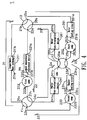
- FIG. 4 schematically illustrates the configuration of a circulation system of a range-extended electric bus in a high-temperature mode according to a preferred embodiment of the present invention.
- the circulation system 1 of the range-extended electric bus of this embodiment is operated in the high-temperature mode
- the first end 21a of the first flow path 21 is controlled to connect with the second end 23b of the third flow path 23 and the second end 22b of the second flow path 22 is controlled to connect with the first end 24a of the fourth flow path 24 by the first flow path switching device 11
- the first end 23a of the third flow path 23 is controlled to connect with the second end 25b of the fifth flow path 25
- the second end 24b of the fourth flow path 24 is controlled to connect with the first end 26a of the sixth flow path 26 by the second flow path switching device 12
- the first end 22a of the second flow path 22 is controlled to connect with the second end 26b of the sixth flow path 26 and the second end 21b of the first flow path 21 is controlled to connect with the first end 25a of the fifth flow
- the cooling fluid with high temperature outputted from the motor cooling circuit 251 is guided to the engine cooling circuit 231 for second-time heating, then guided into the compartment heat exchanger 211 so as to be heat-dissipated for providing the central heating, and finally circulated back to the motor cooling circuit 251.
- the second cycling loop is a loop in a shutdown state that includes the motor heat-dissipation device 261, the engine heat-dissipation device 241 and the liquid temperature adjustment device 221.
- all of the waste heat absorbed in the motor cooling circuit 251 and the engine cooling circuit 231 is used by the compartment heat exchanger 211 for heating, so that the waste heat is completely used for providing the central heating in the compartment.
- the circulation system 1 of the range-extended electric bus which needs the highest heating power for providing the central heating, can be adjusted as the circulation settings shown in FIG. 4 for operating in the high-temperature mode.
- the cooling fluid which absorbs the waste heat, in the motor cooling circuit 251 and the engine cooling circuit 231 is only guided into the compartment heat exchanger 211 to be volatilized for generating the central heating.
- the motor heat-dissipation device 261, the liquid temperature adjustment device 221 and the engine heat-dissipation device 241 are isolated in the other cycling loop.
- the heating power of the compartment heat exchanger 211 has to be highest for ensuring the input temperature of the motor cooling circuit 251 and the engine cooling circuit 231 at an available range of operation temperature.
- FIG. 5 schematically illustrates the configuration of a circulation system of a range-extended electric bus in a medium-temperature mode according to a preferred embodiment of the present invention.
- the circulation system 1 of the range-extended electric bus of this embodiment is operated in the medium-temperature mode
- the first end 21a of the first flow path 21 is controlled to connect with the second end 23b of the third flow path 23 and the second end 22b of the second flow path 22 is controlled to connect with the first end 24a of the fourth flow path 24 by the first flow path switching device 11
- the first end 23a of the third flow path 23 is controlled to connect with the second end 25b of the fifth flow path 25
- the second end 24b of the fourth flow path 24 is controlled to connect with the first end 26a of the sixth flow path 26 by the second flow path switching device 12
- the first end 25a of the fifth flow path 25 is controlled to connect with the second end 26b of the sixth flow path 26 and the second end 21b of the first flow path 21 is controlled to connect with the first end 22a of the second flow
- the cooling fluid which firstly absorbs the waste heat in the motor cooling circuit 251 and the engine cooling circuit 231, is guided into the compartment heat exchanger 211 to be volatilized for providing the central heating, then sequentially guided into the liquid temperature adjustment device 221, the engine heat-dissipation device 241, the motor heat-dissipation device 261 to be cooled for adjusting the temperature of the cooling fluid, and finally circulated back to the motor cooling circuit 251.
- the heating power provided in the medium-temperature mode is lower, however the temperature of the cooling fluid is easier to be kept at an ideal operation temperature.
- the circulation system 1 of the range-extended electric bus which needs higher heating power and higher power output, can be adjusted as the circulation settings shown in FIG. 5 for operating in the medium-temperature mode.
- the cooling fluid which absorbs the waste heat, in the motor cooling circuit 251 and the engine cooling circuit 231 is firstly guided into the compartment heat exchanger 211 to be volatilized for generating the central heating, and then guided to the motor heat-dissipation device 261 and the engine heat-dissipation device 241 for adjusting the input temperature of the cooling fluid toward the motor cooling circuit 251, thereby ensuring to provide a large amount of the central heating and keep the motor system in an available system state for providing high load anytime, simultaneously.
- FIG. 6 schematically illustrates the configuration of a circulation system of a range-extended electric bus in a common cooling mode according to a preferred embodiment of the present invention.
- the circulation system 1 of the range-extended electric bus of this embodiment is operated in the common cooling mode, the first end 21a of the first flow path 21 is controlled to connect with the second end 22b of the second flow path 22 and the second end 23b of the third flow path 23 is controlled to connect with the first end 24a of the fourth flow path 24 by the first flow path switching device 11, the first end 23a of the third flow path 23 is controlled to connect with the second end 25b of the fifth flow path 25 and the second end 24b of the fourth flow path 24 is controlled to connect with the first end 26a of the sixth flow path 26 by the second flow path switching device 12, and the first end 25a of the fifth flow path 25 is controlled to connect with the second end 26b of the sixth flow path 26 and the second end 21b of the first flow path 21 is controlled to connect with the first end 22a of the second flow path 22 by the third
- the engine In the first cycling loop, the engine is in a shutdown state, so there is no thermal energy distributed by the engine cooling circuit 231. Therefore, the waste heat is firstly absorbed by the cooling fluid in the motor cooling circuit 251, then the cooling fluid is guided into the engine heat-dissipation device 241, and then further guided into the motor heat-dissipation device for heat-dissipation.
- the cooling fluid In the second cycling loop, the cooling fluid is circulated between the liquid temperature adjustment device 221 and the compartment heat exchanger 211 for providing air-condition in the compartment.
- the circulation system 1 of the range-extended electric bus can be adjusted as the circulation settings shown in FIG. 6 for operating in the common cooling mode.
- the cooling fluid which absorbs the waste heat in the motor cooling circuit 251 can be heat-dissipated with the engine heat-dissipation device 241 and the motor heat-dissipation device 261, so that a circulation temperature of the cooling fluid may get lower and be more stable.
- connections of the first flow path, the second flow path, the third flow path, the fourth flow path, the fifth flow path and the sixth flow path and a circulation of the cooling fluid are controlled by the first flow path switching device, the second flow path switching device and the third flow path switching device in order to recycle the waste heat generated by a motor and a motor driver of the range-extended electric bus under a cold environment for providing a central heating inside a compartment, and use the cooling power of the air-conditioner system of the electric bus for reducing the operation temperature of a motor system under a hot environment.
- the circulation system of the range-extended electric bus of the present invention can be operated in a plurality of operation modes, such that the circulation system of the range-extended electric bus can satisfy different environment conditions and meet different internal demands for enhancing the efficiency of utilization of internal waste heat and external temperature.
Description
- The present invention relates to a circulation system of a range-extended electric bus, and more particularly to a temperature circulation system of a power system of a range-extended electric bus. The circulation system controls the direction of a circulation of cooling fluid and powers of each component for changing to a plurality of operation modes according to the temperature of the environment and the system cooling demands.
- A cooling method of a range-extended electric bus of prior art utilizes a radiator to volatilize the waste heat, however the cooling power is limited by the temperature of the environment. Under this circumstance, when a large power output is being performed under a hot weather, the temperature of the cooling fluid may be 20 degrees Celsius higher than the ideal operation temperature, easily shortening the lifetimes of the motor driver and the motor system.
- Practically, when the temperature of the environment is risen to 35 degrees Celsius, an output temperature of the water of the radiator may be risen to 50-60 degrees Celsius according to the power of the motor. Since the ideal operation temperature of the motor driver is under 40 degrees Celsius, it is easily causing the efficiency decay and unable output, and shortening the lifetime of the motor system.
-
WO2013190767 (A1 ) discloses a vehicle heat management system in which a heat medium circuit including a first path and a heat medium circuit including second paths are formed independently of each other by operating a first switching valve and a second switching valve in conjunction with each other so that the paths communicated by the first switching valve and the paths communicated by the second switching valve are the same in a plurality of flow channels constituting a first flow channel group. A heat medium circuit in which the first path and the second paths are communicated in series is formed by operating the first switching valve and the second switching valve in conjunction with each other so that the paths communicated by the first switching valve and the paths communicated by the second switching valve are different in the plurality of flow channels constituting the first flow channel group. It is possible through a simple configuration to switch between forming heat medium circuits that are independent for each of a plurality of paths, and forming heat medium circuits by connecting a plurality of paths to each other. - Therefore, there is a need of providing a technique to keep the cooling power under any weather in order to eliminate the above drawbacks of the power system of the electric bus of prior art.
- It is an object of the present invention to provide a circulation system of a range-extended electric bus in order to recycle the waste heat generated by a motor and a motor driver of the range-extended electric bus under a cold environment for providing a central heating inside a compartment, and use the cooling power of the air-conditioner system of the electric bus for reducing the operation temperature of a motor system under a hot environment.
- The present invention also provides a circulation system of a range-extended electric bus. Two circulation systems are jointly used for operating. The controls of the direction of the circulation, the setting of the four-port flow path switching device, the engine power, the cooling power of the liquid temperature adjustment device, the setting of the compartment heat exchanger and the power of the heat-dissipation device are used for operating in six different operation modes: a normal cooling mode, an auxiliary cooling mode, a low-temperature mode, a high-temperature mode, a medium-temperature mode and a common cooling mode.
- In accordance with an aspect of the present invention, there is provided a circulation system of a range-extended electric bus. The circulation system includes cooling fluid, a first flow path, a second flow path, a third flow path, a fourth flow path, a fifth flow path, a sixth flow path, a first flow path switching device, a second flow path switching device and a third flow path switching device. The first flow path includes a compartment heat exchanger. The compartment heat exchanger is used for adjusting the temperature inside a compartment. A first end of the first flow path is connected with a first end of the compartment heat exchanger, and a second end of the first flow path is connected with a second end of the compartment heat exchanger. The second flow path includes a liquid temperature adjustment device and a first pump. The liquid temperature adjustment device is used for controlling the temperature of the cooling fluid outputted from the liquid temperature adjustment device, and the first pump is used for controlling the flow rate of the cooling fluid outputted from the liquid temperature adjustment device. A first end of the second flow path is connected with a first end of the liquid temperature adjustment device, a second end of liquid temperature adjustment device is connected with a first end of the first pump, and a second end of the first pump is connected with a second end of the second flow path. The third flow path includes an engine cooling circuit and a second pump. The engine cooling circuit is used for controlling the temperature of the cooling fluid outputted from the engine cooling circuit, and the second pump is used for controlling the flow rate of the cooling fluid outputted from the engine cooling circuit. A first end of the third flow path is connected with a first end of the engine cooling circuit, a second end of the engine cooling circuit is connected with a first end of the second pump, and a second end of the second pump is connected with a second end of the third flow path. The fourth flow path includes an engine heat-dissipation device. The engine heat-dissipation device is used for adjusting the temperature of an engine, a first end of the fourth flow path is connected with a first end of the engine heat-dissipation device, and a second end of the fourth flow path is connected with a second end of the engine heat-dissipation device. The fifth flow path includes a motor cooling circuit and a third pump. The motor cooling circuit is used for controlling the temperature of the cooling fluid outputted from the motor cooling circuit, and the third pump is used for controlling the flow rate of the cooling fluid outputted from the motor cooling circuit. A first end of the fifth flow path is connected with a first end of the motor cooling circuit, a second end of the motor cooling circuit is connected with a first end of the third pump, and a second end of the fifth flow path is connected with a second end of the third pump. The sixth flow path includes a motor heat-dissipation device. The motor heat-dissipation device is used for adjusting the temperature of a motor, a first end of the sixth flow path is connected with a first end of the motor heat-dissipation device, and a second end of the sixth flow path is connected with a second end of the motor heat-dissipation device. The first flow path switching device is connected with the first end of the first flow path, the second end of the second flow path, the second end of the third flow path and the first end of the fourth flow path for controlling the first end of the first flow path and the first end of the fourth flow path to respectively and selectively connect with the second end of the second flow path and the second end of the third flow path. The second flow path switching device is connected with the first end of the third flow path, the second end of the fourth flow path, the second end of the fifth flow path and the first end of the sixth flow path for controlling the first end of the third flow path and the first end of the sixth flow path to respectively and selectively connect with the second end of the fourth flow path and the second end of the fifth flow path. The third flow path switching device is connected with the first end of the fifth flow path, the second end of the sixth flow path, the second end of the first flow path and the first end of the second flow path for controlling the first end of the fifth flow path and the first end of the second flow path to respectively and selectively connect with the second end of the sixth flow path and the second end of the first flow path. Connections of the first flow path, the second flow path, the third flow path, the fourth flow path, the fifth flow path and the sixth flow path and a circulation of the cooling fluid are controlled by the first flow path switching device, the second flow path switching device and the third flow path switching device, thereby being operated in a plurality of operation modes.
- The above contents of the present invention will become more readily apparent to those ordinarily skilled in the art after reviewing the following detailed description and accompanying drawings, in which:
-
-
FIG. 1 schematically illustrates the configuration of a circulation system of a range-extended electric bus in a normal cooling mode according to a preferred embodiment of the present invention; -
FIG. 2 schematically illustrates the configuration of a circulation system of a range-extended electric bus in an auxiliary cooling mode according to a preferred embodiment of the present invention; -
FIG. 3 schematically illustrates the configuration of a circulation system of a range-extended electric bus in a low-temperature mode according to a preferred embodiment of the present invention; -
FIG. 4 schematically illustrates the configuration of a circulation system of a range-extended electric bus in a high-temperature mode according to a preferred embodiment of the present invention; -
FIG. 5 schematically illustrates the configuration of a circulation system of a range-extended electric bus in a medium-temperature mode according to a preferred embodiment of the present invention; and -
FIG. 6 schematically illustrates the configuration of a circulation system of a range-extended electric bus in a common cooling mode according to a preferred embodiment of the present invention. - The present invention will now be described more specifically with reference to the following embodiments. It is to be noted that the following descriptions of preferred embodiments of this invention are presented herein for purpose of illustration and description only. It is not intended to be exhaustive or to be limited to the precise form disclosed.
- Please refer to
FIG. 1. FIG. 1 schematically illustrates the configuration of a circulation system of a range-extended electric bus in a normal cooling mode according to a preferred embodiment of the present invention. Acirculation system 1 of a range-extended electric bus includes afirst flow path 21, asecond flow path 22, athird flow path 23, afourth flow path 24, afifth flow path 25 and asixth flow path 26. Thefirst flow path 21, thesecond flow path 22, thethird flow path 23, thefourth flow path 24, thefifth flow path 25 and thesixth flow path 26, which are not limited to be pipes having liquid flow paths, has cooling fluid inside. The cooling fluid is not limited to water. - The
first flow path 21 includes acompartment heat exchanger 211. Afirst end 21a of thefirst flow path 21 is connected with a first end 211a of thecompartment heat exchanger 211, and asecond end 21b of thefirst flow path 21 is connected with asecond end 211b of thecompartment heat exchanger 211. Thecompartment heat exchanger 211 is not limited to a heat exchange being used for reducing or providing the temperature inside a compartment with the cooling fluid. Thesecond flow path 22 includes a liquidtemperature adjustment device 221 and afirst pump 222. The liquidtemperature adjustment device 221 is used for controlling the temperature of the cooling fluid outputted from the liquidtemperature adjustment device 221. A first end 22a of thesecond flow path 22 is connected with afirst end 221a of the liquidtemperature adjustment device 221, asecond end 221b of liquidtemperature adjustment device 221 is connected with afirst end 222a of thefirst pump 222, and asecond end 222b of thefirst pump 222 is connected with asecond end 22b of thesecond flow path 22. The liquidtemperature adjustment device 221 is not limited to a cold-water supplying device using a refrigerant compression circulation system in order to achieve the purpose of refrigeration. - The
third flow path 23 includes anengine cooling circuit 231 and asecond pump 232. Theengine cooling circuit 231 is used for controlling the temperature of the cooling fluid outputted from theengine cooling circuit 231. A first end 23a of thethird flow path 23 is connected with afirst end 231a of theengine cooling circuit 231, asecond end 231b of theengine cooling circuit 231 is connected with afirst end 232a of thesecond pump 232, and asecond end 232b of thesecond pump 232 is connected with asecond end 23b of thethird flow path 23. Theengine cooling circuit 231 is not limited to a cooling fluid circulation flow path inside a range-extended power generator for conducting the waste heat generated during powering to the cooling fluid, or a fuel battery or a heat pump. Thefourth flow path 24 includes an engine heat-dissipation device 241. The engine heat-dissipation device 241 is used for adjusting the temperature of an engine, afirst end 24a of thefourth flow path 24 is connected with afirst end 241a of the engine heat-dissipation device 241, and asecond end 24b of thefourth flow path 24 is connected with asecond end 241b of the engine heat-dissipation device 241. The engine heat-dissipation device 241 is not limited to a radiator using the air of the environment to reduce the temperature of the cooling fluid, and is mainly used for cooling the cooling fluid circulated by theengine cooling circuit 231. In addition, theengine cooling circuit 231 and the engine heat-dissipation device 241 can be respectively a fossil fuel boiler and a bypass pipe, simultaneously. - The
fifth flow path 25 includes amotor cooling circuit 251 and athird pump 252. Themotor cooling circuit 251 is used for controlling the temperature of the cooling fluid outputted from themotor cooling circuit 251. Afirst end 25a of thefifth flow path 25 is connected with afirst end 251a of themotor cooling circuit 251, asecond end 251b of themotor cooling circuit 251 is connected with afirst end 252a of thethird pump 252, and asecond end 25b of thefifth flow path 25 is connected with asecond end 252b of thethird pump 252. Themotor cooling circuit 251 is not limited to a cooling circulation flow path circulated in a motor system (not shown) and a motor driver (not shown) for absorbing the waste heat. Thesixth flow path 26 includes a motor heat-dissipation device 261. The motor heat-dissipation device 261 is used for adjusting the temperature of a motor, afirst end 26a of thesixth flow path 26 is connected with afirst end 261a of the motor heat-dissipation device 261, and asecond end 26b of thesixth flow path 26 is connected with asecond end 261b of the motor heat-dissipation device 261. The motor heat-dissipation device 261 is not limited to a radiator using the air of the environment to reduce the temperature of the cooling fluid, and is mainly used for cooling the cooling fluid circulated by themotor cooling circuit 251. - Moreover, the
first pump 222, thesecond pump 232 and thethird pump 252 are not limited to water pumps, thefirst pump 222 is used for controlling the flow rate of the cooling fluid outputted from the liquidtemperature adjustment device 221, thesecond pump 232 is used for controlling the flow rate of the cooling fluid outputted from theengine cooling circuit 231, and thethird pump 252 is used for controlling the flow rate of the cooling fluid outputted from themotor cooling circuit 251. - In this embodiment, the
circulation system 1 of the range-extended electric bus further includes a first flowpath switching device 11, a second flow path switching device and a third flowpath switching device 13. The first flowpath switching device 11, the second flowpath switching device 12 and the third flowpath switching device 13 are not limited to four-port flow path switching devices. - The first flow
path switching device 11 is connected with thefirst end 21a of thefirst flow path 21, thesecond end 22b of thesecond flow path 22, thesecond end 23b of thethird flow path 23 and thefirst end 24a of thefourth flow path 24 for controlling thefirst end 21a of thefirst flow path 21 and thefirst end 24a of thefourth flow path 24 to respectively and selectively connect with thesecond end 22b of thesecond flow path 22 and thesecond end 23b of thethird flow path 23 according to the settings of a user or other requirements. For example, thefirst end 21a of thefirst flow path 21 can be controlled to connect with thesecond end 22b of thesecond flow path 22 and thefirst end 24a of thefourth flow path 24 can be controlled to connect with thesecond end 23b of thethird flow path 23 by the first flowpath switching device 11, or thefirst end 21a of thefirst flow path 21 can be controlled to connect with thesecond end 23b of thethird flow path 23 and thefirst end 24a of thefourth flow path 24 can be controlled to connect with thesecond end 22b of thesecond flow path 22 by the first flowpath switching device 11. - The second flow
path switching device 12 is connected with the first end 23a of thethird flow path 23, thesecond end 24b of thefourth flow path 24, thesecond end 25b of thefifth flow path 25 and thefirst end 26a of thesixth flow path 26 for controlling the first end 23a of thethird flow path 23 and thefirst end 26a of thesixth flow path 26 to respectively and selectively connect with thesecond end 24b of thefourth flow path 24 and thesecond end 25b of thefifth flow path 25 according to the settings of a user or other requirements. For example, the first end 23a of thethird flow path 23 can be controlled to connect with thesecond end 24b of thefourth flow path 24 and thefirst end 26a of thesixth flow path 26 can be controlled to connect with thesecond end 25b of thefifth flow path 25 by the second flowpath switching device 12, or the first end 23a of thethird flow path 23 can be controlled to connect with thesecond end 25b of thefifth flow path 25 and thefirst end 26a of thesixth flow path 26 can be controlled to connect with thesecond end 24b of thefourth flow path 24 by the second flowpath switching device 12. - The third flow
path switching device 13 is connected with thefirst end 25a of thefifth flow path 25, thesecond end 26b of thesixth flow path 26, thesecond end 21b of thefirst flow path 21 and the first end 22a of thesecond flow path 22 for controlling thefirst end 25a of thefifth flow path 25 and the first end 22a of thesecond flow path 22 to respectively and selectively connect with thesecond end 26b of thesixth flow path 26 and thesecond end 21b of thefirst flow path 21 according to the settings of a user or other requirements. For example, thefirst end 25a of thefifth flow path 25 can be controlled to connect with thesecond end 26b of thesixth flow path 26 and the first end 22a of thesecond flow path 22 can be controlled to connect with thesecond end 21b of thefirst flow path 21 by the third flowpath switching device 13, or thefirst end 25a of thefifth flow path 25 can be controlled to connect with thesecond end 21b of thefirst flow path 21 and the first end 22a of thesecond flow path 22 can be controlled to connect with thesecond end 26b of thesixth flow path 26 by the third flowpath switching device 13. - In the
circulation system 1 of the range-extended electric bus of the present invention, not only connections of thefirst flow path 21, thesecond flow path 22, thethird flow path 23, thefourth flow path 24, thefifth flow path 25 and thesixth flow path 26, but also a circulation of the cooling fluid inside the circulation paths are controlled by the first flowpath switching device 11, the second flowpath switching device 12 and the third flowpath switching device 13, such that thecirculation system 1 of the range-extended electric bus is operated in a plurality of operation modes. The operation modes include but not limited to a normal cooling mode, an auxiliary cooling mode, a low-temperature mode, a high-temperature mode, a medium-temperature mode and a common cooling mode illustrated as follows. - Please refer to
FIG. 1 again. When thecirculation system 1 of the range-extended electric bus of this embodiment is operated in the normal cooling mode, thefirst end 21a of thefirst flow path 21 is controlled to connect with thesecond end 22b of thesecond flow path 22 and thesecond end 23b of thethird flow path 23 is controlled to connect with thefirst end 24a of thefourth flow path 24 by the first flowpath switching device 11, the first end 23a of thethird flow path 23 is controlled to connect with thesecond end 24b of thefourth flow path 24 and thesecond end 25b of thefifth flow path 25 is controlled to connect with thefirst end 26a of thesixth flow path 26 by the second flowpath switching device 12, and thefirst end 25a of thefifth flow path 25 is controlled to connect with thesecond end 26b of thesixth flow path 26 and thesecond end 21b of thefirst flow path 21 is controlled to connect with the first end 22a of thesecond flow path 22 by the third flowpath switching device 13. Three cycling loops are formed by thecirculation system 1 of the range-extended electric bus. The first cycling loop is consisted of thefirst flow path 21 and thesecond flow path 22. Thefirst pump 222 is used for circulating the cooling fluid in thecompartment heat exchanger 211 and the liquidtemperature adjustment device 221. The second cycling loop is consisted of thethird flow path 23 and thefourth flow path 24. Thesecond pump 232 is used for circulating the cooling fluid in theengine cooling circuit 231 and the engine heat-dissipation device 241. The third cycling loop is consisted of thefifth flow path 25 and thesixth flow path 26. Thethird pump 252 is used for circulating the cooling fluid in themotor cooling circuit 251 and the motor heat-dissipation device 261. - When the range-extended electric bus is operated in an environment with a moderate temperature, the
circulation system 1 of the range-extended electric bus is adjusted as the circulation settings shown inFIG. 1 for operating in the normal cooling mode. The liquidtemperature adjustment device 221 provides the cooling fluid with low temperature to thecompartment heat exchanger 211 for cooling the air inside the compartment according to the demands of the user. Theengine cooling circuit 231 and the engine heat-dissipation device 241 circulate the cooling fluid when the engine is enable for being charged, so that the engine may be capable of heat-dissipation through the circulation of the cooling fluid. The cooling fluid with high temperature in themotor cooling circuit 251 is guided to the motor heat-dissipation device 261 for as much as possible keeping the low-temperature circulation in order to ensure the efficiencies of the motor system and the motor driver. - Please refer to
FIG. 2. FIG. 2 schematically illustrates the configuration of a circulation system of a range-extended electric bus in an auxiliary cooling mode according to a preferred embodiment of the present invention. When thecirculation system 1 of the range-extended electric bus of this embodiment is operated in the auxiliary cooling mode, thefirst end 21a of thefirst flow path 21 is controlled to connect with thesecond end 22b of thesecond flow path 22 and thesecond end 23b of thethird flow path 23 is controlled to connect with thefirst end 24a of thefourth flow path 24 by the first flowpath switching device 11, the first end 23a of thethird flow path 23 is controlled to connect with thesecond end 24b of thefourth flow path 24 and thesecond end 25b of thefifth flow path 25b is controlled to connect with thefirst end 26a of thesixth flow path 26 by the second flowpath switching device 12, and the first end 22a of thesecond flow path 22 is controlled to connect with thesecond end 26b of thesixth flow path 26 and thesecond end 21b of thefirst flow path 21 is controlled to connect with thefirst end 25a of thefifth flow path 25 by the third flowpath switching device 13, such that two cycling loops are formed by thecirculation system 1 of the range-extended electric bus. The first cycling loop is consisted of thefirst flow path 21, thesecond flow path 22, thefifth flow path 25 and thesixth flow path 26. Thefirst pump 222 and thethird pump 252 are used for circulating the cooling fluid around thecompartment heat exchanger 211, the liquidtemperature adjustment device 221, themotor cooling circuit 251 and the motor heat-dissipation device 261, so that the cooling fluid, which absorbs the waste heat of themotor cooling circuit 251, with high temperature can be cooled by the motor heat-dissipation device 261, and then cooled by the liquidtemperature adjustment device 221, circulated over thecompartment heat exchanger 211 for providing the air-condition, and finally circulated back to themotor cooling circuit 251. No matter whether the temperature of the environment is too high or not, the input temperature of the cooling fluid toward themotor cooling circuit 251 can be controlled at an ideal operation temperature. In the second cycling loop, thesecond pump 232 is used for circulating the cooling fluid between theengine cooling circuit 231 and the engine heat-dissipation device 241. - When the temperature of the environment is risen or the waste heat of the motor system is too much, causing that the motor system cannot be kept at an ideal operation temperature, the
circulation system 1 of the range-extended electric bus is adjusted as the circulation settings shown inFIG. 2 for operating in the auxiliary cooling mode. In the auxiliary cooling mode, when the cooling fluid, which absorbs the waste heat, with high temperature in themotor cooling circuit 251 is guided to the liquidtemperature adjustment device 221, the heat is effectively absorbed through the refrigerant compression circulation system, so that the temperature of the cooling fluid is lower than the temperature of the environment. The cooling fluid is then circulated back to themotor cooling circuit 251 through the third flowpath switching device 13, so that the input temperature of the cooling fluid toward themotor cooling circuit 251 is kept at a low temperature for protecting the motor system and the motor driver. Even if the temperature of the environment is risen to 40 degrees Celsius, the temperature-controlling manner of the auxiliary cooling mode may much more ensure that the motor system can be operated at a temperature between 20 to 40 degrees Celsius in comparison with a conventional temperature-controlling manner of prior art. Therefore, the motor system and the motor driver can be long-term stable. - Please refer to
FIG. 3. FIG. 3 schematically illustrates the configuration of a circulation system of a range-extended electric bus in a low-temperature mode according to a preferred embodiment of the present invention. When thecirculation system 1 of the range-extended electric bus of this embodiment is operated in the low-temperature mode, thefirst end 21a of thefirst flow path 21 is controlled to connect with thesecond end 23b of thethird flow path 23 and thesecond end 22b of thesecond flow path 22 is controlled to connect with thefirst end 24a of thefourth flow path 24 by the first flowpath switching device 11, the first end 23a of thethird flow path 23 is controlled to connect with thesecond end 24b of thefourth flow path 24 and thesecond end 25b of thefifth flow path 25 is controlled to connect with thefirst end 26a of thesixth flow path 26 by the second flowpath switching device 12, and the first end 22a of thesecond flow path 22 is controlled to connect with thesecond end 26b of thesixth flow path 26 and thesecond end 21b of thefirst flow path 21 is controlled to connect with thefirst end 25a of thefifth flow path 25 by the third flowpath switching device 13, such that a cycling loop is formed by thecirculation system 1 of the range-extended electric bus. In this cycling loop, the cooling fluid with high temperature outputted from themotor cooling circuit 251 is circulated through the motor heat-dissipation device 261, the liquidtemperature adjustment device 221, the engine heat-dissipation device 241 so as to be cooled. The cooled cooling fluid is guided to theengine cooling circuit 231 so as to be heated, then volatilized with the waste heat for providing the central heating in thecompartment heat exchanger 211, and finally circulated back to themotor cooling circuit 251. At this time, the waste heat can be volatilized by the motor heat-dissipation device 261, the engine heat-dissipation device 241 and thecompartment heat exchanger 211. In this mode, a portion of the waste heat is utilized for providing the central heating inside the compartment. The liquidtemperature adjustment device 221 is shut down in this mode without providing refrigeration. - When the temperature of the environment is lowered, the
circulation system 1 of the range-extended electric bus can be adjusted as the circulation settings shown inFIG. 3 for operating in the low-temperature mode. The cooling fluid, which absorbs the waste heat, in themotor cooling circuit 251 and theengine cooling circuit 231 can be guided into thecompartment heat exchanger 211 for generating the central heating. The motor heat-dissipation device 261 and the engine heat-dissipation device 241 jointly operate for keeping the cooling fluid at an ideal operation temperature. - Please refer to
FIG. 4. FIG. 4 schematically illustrates the configuration of a circulation system of a range-extended electric bus in a high-temperature mode according to a preferred embodiment of the present invention. When thecirculation system 1 of the range-extended electric bus of this embodiment is operated in the high-temperature mode, thefirst end 21a of thefirst flow path 21 is controlled to connect with thesecond end 23b of thethird flow path 23 and thesecond end 22b of thesecond flow path 22 is controlled to connect with thefirst end 24a of thefourth flow path 24 by the first flowpath switching device 11, the first end 23a of thethird flow path 23 is controlled to connect with thesecond end 25b of thefifth flow path 25 and thesecond end 24b of thefourth flow path 24 is controlled to connect with thefirst end 26a of thesixth flow path 26 by the second flowpath switching device 12, and the first end 22a of thesecond flow path 22 is controlled to connect with thesecond end 26b of thesixth flow path 26 and thesecond end 21b of thefirst flow path 21 is controlled to connect with thefirst end 25a of thefifth flow path 25 by the third flowpath switching device 13, such that two cycling loops are formed by thecirculation system 1 of the range-extended electric bus. In the first cycling loop, the cooling fluid with high temperature outputted from themotor cooling circuit 251 is guided to theengine cooling circuit 231 for second-time heating, then guided into thecompartment heat exchanger 211 so as to be heat-dissipated for providing the central heating, and finally circulated back to themotor cooling circuit 251. The second cycling loop is a loop in a shutdown state that includes the motor heat-dissipation device 261, the engine heat-dissipation device 241 and the liquidtemperature adjustment device 221. In this high-temperature mode, all of the waste heat absorbed in themotor cooling circuit 251 and theengine cooling circuit 231 is used by thecompartment heat exchanger 211 for heating, so that the waste heat is completely used for providing the central heating in the compartment. - When the temperature of the environment is extremely low, the
circulation system 1 of the range-extended electric bus, which needs the highest heating power for providing the central heating, can be adjusted as the circulation settings shown inFIG. 4 for operating in the high-temperature mode. In this mode, the cooling fluid, which absorbs the waste heat, in themotor cooling circuit 251 and theengine cooling circuit 231 is only guided into thecompartment heat exchanger 211 to be volatilized for generating the central heating. The motor heat-dissipation device 261, the liquidtemperature adjustment device 221 and the engine heat-dissipation device 241 are isolated in the other cycling loop. At this time, the heating power of thecompartment heat exchanger 211 has to be highest for ensuring the input temperature of themotor cooling circuit 251 and theengine cooling circuit 231 at an available range of operation temperature. - Please refer to
FIG. 5. FIG. 5 schematically illustrates the configuration of a circulation system of a range-extended electric bus in a medium-temperature mode according to a preferred embodiment of the present invention. When thecirculation system 1 of the range-extended electric bus of this embodiment is operated in the medium-temperature mode, thefirst end 21a of thefirst flow path 21 is controlled to connect with thesecond end 23b of thethird flow path 23 and thesecond end 22b of thesecond flow path 22 is controlled to connect with thefirst end 24a of thefourth flow path 24 by the first flowpath switching device 11, the first end 23a of thethird flow path 23 is controlled to connect with thesecond end 25b of thefifth flow path 25 and thesecond end 24b of thefourth flow path 24 is controlled to connect with thefirst end 26a of thesixth flow path 26 by the second flowpath switching device 12, and thefirst end 25a of thefifth flow path 25 is controlled to connect with thesecond end 26b of thesixth flow path 26 and thesecond end 21b of thefirst flow path 21 is controlled to connect with the first end 22a of thesecond flow path 22 by the third flowpath switching device 13, such that a cycling loop is formed by thecirculation system 1 of the range-extended electric bus. In this cycling loop, the cooling fluid, which firstly absorbs the waste heat in themotor cooling circuit 251 and theengine cooling circuit 231, is guided into thecompartment heat exchanger 211 to be volatilized for providing the central heating, then sequentially guided into the liquidtemperature adjustment device 221, the engine heat-dissipation device 241, the motor heat-dissipation device 261 to be cooled for adjusting the temperature of the cooling fluid, and finally circulated back to themotor cooling circuit 251. In comparison with the high-temperature mode shown inFIG. 4 , the heating power provided in the medium-temperature mode is lower, however the temperature of the cooling fluid is easier to be kept at an ideal operation temperature. - When the temperature of the environment is low, the
circulation system 1 of the range-extended electric bus, which needs higher heating power and higher power output, can be adjusted as the circulation settings shown inFIG. 5 for operating in the medium-temperature mode. In this mode, the cooling fluid, which absorbs the waste heat, in themotor cooling circuit 251 and theengine cooling circuit 231 is firstly guided into thecompartment heat exchanger 211 to be volatilized for generating the central heating, and then guided to the motor heat-dissipation device 261 and the engine heat-dissipation device 241 for adjusting the input temperature of the cooling fluid toward themotor cooling circuit 251, thereby ensuring to provide a large amount of the central heating and keep the motor system in an available system state for providing high load anytime, simultaneously. - Please refer to
FIG. 6. FIG. 6 schematically illustrates the configuration of a circulation system of a range-extended electric bus in a common cooling mode according to a preferred embodiment of the present invention. When thecirculation system 1 of the range-extended electric bus of this embodiment is operated in the common cooling mode, thefirst end 21a of thefirst flow path 21 is controlled to connect with thesecond end 22b of thesecond flow path 22 and thesecond end 23b of thethird flow path 23 is controlled to connect with thefirst end 24a of thefourth flow path 24 by the first flowpath switching device 11, the first end 23a of thethird flow path 23 is controlled to connect with thesecond end 25b of thefifth flow path 25 and thesecond end 24b of thefourth flow path 24 is controlled to connect with thefirst end 26a of thesixth flow path 26 by the second flowpath switching device 12, and thefirst end 25a of thefifth flow path 25 is controlled to connect with thesecond end 26b of thesixth flow path 26 and thesecond end 21b of thefirst flow path 21 is controlled to connect with the first end 22a of thesecond flow path 22 by the third flowpath switching device 13, such that two cycling loops are formed by thecirculation system 1 of the range-extended electric bus. In the first cycling loop, the engine is in a shutdown state, so there is no thermal energy distributed by theengine cooling circuit 231. Therefore, the waste heat is firstly absorbed by the cooling fluid in themotor cooling circuit 251, then the cooling fluid is guided into the engine heat-dissipation device 241, and then further guided into the motor heat-dissipation device for heat-dissipation. In the second cycling loop, the cooling fluid is circulated between the liquidtemperature adjustment device 221 and thecompartment heat exchanger 211 for providing air-condition in the compartment. - When the temperature of the environment is high but the engine is not operating, the
circulation system 1 of the range-extended electric bus, can be adjusted as the circulation settings shown inFIG. 6 for operating in the common cooling mode. In this mode, the cooling fluid, which absorbs the waste heat in themotor cooling circuit 251, can be heat-dissipated with the engine heat-dissipation device 241 and the motor heat-dissipation device 261, so that a circulation temperature of the cooling fluid may get lower and be more stable. - From the above descriptions, in a circulation system of a range-extended electric bus of the present invention, connections of the first flow path, the second flow path, the third flow path, the fourth flow path, the fifth flow path and the sixth flow path and a circulation of the cooling fluid are controlled by the first flow path switching device, the second flow path switching device and the third flow path switching device in order to recycle the waste heat generated by a motor and a motor driver of the range-extended electric bus under a cold environment for providing a central heating inside a compartment, and use the cooling power of the air-conditioner system of the electric bus for reducing the operation temperature of a motor system under a hot environment. In addition, by controlling the circulation flow path of the cooling fluid and the settings of the flow path switching devices, the circulation system of the range-extended electric bus of the present invention can be operated in a plurality of operation modes, such that the circulation system of the range-extended electric bus can satisfy different environment conditions and meet different internal demands for enhancing the efficiency of utilization of internal waste heat and external temperature.
Claims (10)
- A circulation system (1) of a range-extended electric bus, comprising:
cooling fluid;
characterized bya first flow path (21) comprising a compartment heat exchanger (211), wherein the compartment heat exchanger is used for adjusting the temperature inside a compartment, a first end (21a) of the first flow path is connected with a first end of the compartment heat exchanger (221a), and a second end (21b) of the first flow path is connected with a second end (221b) of the compartment heat exchanger;a second flow path (22) comprising a liquid temperature adjustment device (221) and a first pump (222), wherein the liquid temperature adjustment device is used for controlling the temperature of the cooling fluid outputted from the liquid temperature adjustment device, and the first pump is used for controlling the flow rate of the cooling fluid outputted from the liquid temperature adjustment device, and wherein a first end (22a) of the second flow path is connected with a first end (221a) of the liquid temperature adjustment device, a second end (221b) of liquid temperature adjustment device is connected with a first end (222a) of the first pump, and a second end (222b) of the first pump is connected with a second end (22b) of the second flow path;a third flow path (23) comprising an engine cooling circuit (231) and a second pump (232), wherein the engine cooling circuit is used for controlling the temperature of the cooling fluid outputted from the engine cooling circuit, and the second pump is used for controlling the flow rate of the cooling fluid outputted from the engine cooling circuit, and wherein a first end (23a) of the third flow path is connected with a first end (231a) of the engine cooling circuit, a second end (231b) of the engine Cooling circuit is connected with a first end (232a) of the second pump, and a second end (232b) of the second pump is connected with a second end (23b) of the third flow path;a fourth flow path (24) comprising an engine heat-dissipation device (241), wherein the engine heat-dissipation device is used for adjusting the temperature of an engine, a first end (241a) of the fourth flow path (24) is connected with a first end (241a) of the engine heat-dissipation device, and a second end (24b) of the fourth flow path (24) is connected with a second end (241b) of the engine heat-dissipation device;a fifth flow path (25) comprising a motor cooling circuit (251) and a third pump (252), wherein the motor cooling circuit is used for controlling the temperature of the cooling fluid outputted from the motor cooling circuit, and the third pump is used for controlling the flow rate of the cooling fluid outputted from the motor cooling circuit, and wherein a first end (25a) of the fifth flow path is connected with a first end (251a) of the motor cooling circuit, a second end (251b) of the motor cooling circuit is connected with a first end (252a) of the third pump, and a second end (25b) of the fifth flow path (25) is connected with a second end (252b) of the third pump;a sixth flow path (26) comprising a motor heat-dissipation device (261), wherein the motor heat-dissipation device is used for adjusting the temperature of a motor, a first end (26a) of the sixth flow path (26) is connected with a first end (261a) of the motor heat-dissipation device, and a second end (26b) of the sixth flow path is connected with a second end (261b) of the motor heat-dissipation device;a first flow path switching device (11) connected with the first end of the first flow path, the second end of the second flow path, the second end of the third flow path and the first end of the fourth flow path for controlling the first end of the first flow path and the first end of the fourth flow path to respectively and selectively connect with the second end of the second flow path and the second end of the third flow path;a second flow path switching device (12) connected with the first end of the third flow path, the second end of the fourth flow path, the second end of the fifth flow path and the first end of the sixth flow path for controlling the first end of the third flow path and the first end of the sixth flow path to respectively and selectively connect with the second end of the fourth flow path and the second end of the fifth flow path; anda third flow path switching device (13) connected with the first end of the fifth flow path, the second end of the sixth flow path, the second end of the first flow path and the first end of the second flow path for controlling the first end of the fifth flow path and the first end of the second flow path to respectively and selectively connect with the second end of the sixth flow path and the second end of the first flow path,wherein connections of the first flow path, the second flow path, the third flow path, the fourth flow path, the fifth flow path and the sixth flow path and a circulation of the cooling fluid are controlled by the first flow path switching device, the second flow path switching device and the third flow path switching device, thereby being operated in a plurality of operation modes. - The circulation system of the range-extended electric bus according to claim 1, wherein the operation modes include a normal cooling mode, and wherein in the normal cooling mode, the first end of the first flow path is controlled to connect with the second end of the second flow path and the second end of the third flow path is controlled to connect with the first end of the fourth flow path by the first flow path switching device, the first end of the third flow path is controlled to connect with the second end of the fourth flow path and the second end of the fifth flow path is controlled to connect with the first end of the sixth flow path by the second flow path switching device, and the first end of the fifth flow path is controlled to connect with the second end of the sixth flow path and the second end of the first flow path is controlled to connect with the first end of the second flow path by the third flow path switching device.
- The circulation system of the range-extended electric bus according to claim 1, wherein the operation modes include an auxiliary cooling mode, and wherein in the auxiliary cooling mode, the first end of the first flow path is controlled to connect with the second end of the second flow path and the second end of the third flow path is controlled to connect with the first end of the fourth flow path by the first flow path switching device, the first end of the third flow path is controlled to connect with the second end of the fourth flow path and the second end of the fifth flow path is controlled to connect with the first end of the sixth flow path by the second flow path switching device, and the first end of the second flow path is controlled to connect with the second end of the sixth flow path and the second end of the first flow path is controlled to connect with the first end of the fifth flow path by the third flow path switching device, so that the cooling fluid outputted from the motor cooling circuit is received and cooled by the liquid temperature adjustment device.
- The circulation system of the range-extended electric bus according to claim 1, wherein the operation modes include a low-temperature mode, and wherein in the low-temperature mode, the first end of the first flow path is controlled to connect with the second end of the third flow path and the second end of the second flow path is controlled to connect with the first end of the fourth flow path by the first flow path switching device, the first end of the third flow path is controlled to connect with the second end of the fourth flow path and the second end of the fifth flow path is controlled to connect with the first end of the sixth flow path by the second flow path switching device, and the first end of the second flow path is controlled to connect with the second end of the sixth flow path and the second end of the first flow path is controlled to connect with the first end of the fifth flow path by the third flow path switching device, so that the cooling fluid outputted from the engine cooling circuit is received and cooled by the compartment heat exchanger.
- The circulation system of the range-extended electric bus according to claim 1, wherein the operation modes include a high-temperature mode, and wherein in the high-temperature mode, the first end of the first flow path is controlled to connect with the second end of the third flow path and the second end of the second flow path is controlled to connect with the first end of the fourth flow path by the first flow path switching device, the first end of the third flow path is controlled to connect with the second end of the fifth flow path and the second end of the fourth flow path is controlled to connect with the first end of the sixth flow path by the second flow path switching device, and the first end of the second flow path is controlled to connect with the second end of the sixth flow path and the second end of the first flow path is controlled to connect with the first end of the fifth flow path by the third flow path switching device, so that a waste heat of the motor cooling circuit and the engine cooling circuit is heat-dissipated by the compartment heat exchanger.
- The circulation system of the range-extended electric bus according to claim 1, wherein the operation modes include a medium-temperature mode, and wherein in the medium-temperature mode, the first end of the first flow path is controlled to connect with the second end of the third flow path and the second end of the second flow path is controlled to connect with the first end of the fourth flow path by the first flow path switching device, the first end of the third flow path is controlled to connect with the second end of the fifth flow path and the second end of the fourth flow path is controlled to connect with the first end of the sixth flow path by the second flow path switching device, and the first end of the fifth flow path is controlled to connect with the second end of the sixth flow path and the second end of the first flow path is controlled to connect with the first end of the second flow path by the third flow path switching device, so that the cooling fluid in the motor cooling circuit and the engine cooling circuit is circulated in the compartment heat exchanger, the liquid temperature adjustment device, the engine heat-dissipation device and the motor cooling circuit.
- The circulation system of the range-extended electric bus according to claim 1, wherein the operation modes include a common cooling mode, and wherein in the common cooling mode, the first end of the first flow path is controlled to connect with the second end of the second flow path and the second end of the third flow path is controlled to connect with the first end of the fourth flow path by the first flow path switching device, the first end of the third flow path is controlled to connect with the second end of the fifth flow path and the second end of the fourth flow path is controlled to connect with the first end of the sixth flow path by the second flow path switching device, and the first end of the fifth flow path is controlled to connect with the second end of the sixth flow path and the second end of the first flow path is controlled to connect with the first end of the second flow path by the third flow path switching device, so that the cooling fluid is outputted to the engine heat-dissipation device and the motor heat-dissipation device by the motor cooling circuit for heat-dissipation.
- The circulation system of the range-extended electric bus according to claim 1, wherein the engine cooling circuit is a fuel battery or a heat pump.
- The circulation system of the range-extended electric bus according to claim 1, wherein the engine cooling circuit is a fossil fuel boiler.
- The circulation system of the range-extended electric bus according to claim 9, wherein the engine heat-dissipation device is a bypass pipe.
Applications Claiming Priority (2)
| Application Number | Priority Date | Filing Date | Title |
|---|---|---|---|
| US201461968766P | 2014-03-21 | 2014-03-21 | |
| PCT/CN2015/074803 WO2015139662A1 (en) | 2014-03-21 | 2015-03-20 | Circulation system for extended-range electric bus |
Publications (3)
| Publication Number | Publication Date |
|---|---|
| EP3121043A1 EP3121043A1 (en) | 2017-01-25 |
| EP3121043A4 EP3121043A4 (en) | 2017-11-22 |
| EP3121043B1 true EP3121043B1 (en) | 2018-11-21 |
Family
ID=54143770
Family Applications (1)
| Application Number | Title | Priority Date | Filing Date |
|---|---|---|---|
| EP15764700.9A Not-in-force EP3121043B1 (en) | 2014-03-21 | 2015-03-20 | Circulation system for extended-range electric bus |
Country Status (8)
| Country | Link |
|---|---|
| US (1) | US20180170144A1 (en) |
| EP (1) | EP3121043B1 (en) |
| JP (1) | JP6279142B2 (en) |
| KR (1) | KR101921807B1 (en) |
| CN (1) | CN106457969B (en) |
| CA (1) | CA2943304C (en) |
| TW (1) | TWI577579B (en) |
| WO (1) | WO2015139662A1 (en) |
Families Citing this family (14)
| Publication number | Priority date | Publication date | Assignee | Title |
|---|---|---|---|---|
| US10220672B2 (en) | 2014-03-21 | 2019-03-05 | Aleees Eco Ark Co. Ltd. | Thermal control system of electric vehicle |
| KR101551097B1 (en) * | 2014-06-11 | 2015-09-08 | 현대자동차주식회사 | Heating system of hybrid vehicle |
| US20160318409A1 (en) * | 2015-04-28 | 2016-11-03 | Atieva, Inc. | EV Muti-Mode Thermal Control System |
| US9844995B2 (en) | 2015-04-28 | 2017-12-19 | Atieva, Inc. | EV muti-mode thermal control system |
| FR3061110B1 (en) * | 2016-12-26 | 2019-05-03 | Renault S.A.S. | METHOD FOR CONTROLLING A COOLING SYSTEM FOR A HYBRID VEHICLE HAVING A COOLANT TRANSFER CIRCUIT |
| JP2019089524A (en) * | 2017-11-17 | 2019-06-13 | アイシン精機株式会社 | Vehicular heat exchange device |
| JP2019093990A (en) * | 2017-11-27 | 2019-06-20 | トヨタ自動車株式会社 | Control device of vehicle |
| FR3078386B1 (en) * | 2018-02-28 | 2020-01-24 | Psa Automobiles Sa | THERMAL SYSTEM OF A HYBRID OR ELECTRIC VEHICLE COMPRISING THREE LOOPS OF HEAT FLUID |
| KR102530943B1 (en) * | 2018-07-25 | 2023-05-11 | 현대자동차주식회사 | Thermal management system for vehicle |
| US11021041B2 (en) * | 2019-06-18 | 2021-06-01 | Ford Global Technologies, Llc | Integrated thermal management system |
| FR3108563A1 (en) * | 2020-03-30 | 2021-10-01 | Renault S.A.S | Thermal management device for a hybrid motor vehicle |
| CN112455212B (en) * | 2020-12-04 | 2022-04-19 | 浙江吉利控股集团有限公司 | Cooling control method and system for vehicle electric driving cooling loop |
| CN112721737B (en) * | 2021-01-20 | 2023-02-17 | 重庆邮电大学 | Comprehensive heat energy utilization and heat management system of pure electric vehicle and control method thereof |
| US20230241943A1 (en) * | 2022-02-03 | 2023-08-03 | Kamil Podhola | Auxiliary engine electric car heating system |
Family Cites Families (20)
| Publication number | Priority date | Publication date | Assignee | Title |
|---|---|---|---|---|
| US4403645A (en) * | 1978-07-12 | 1983-09-13 | Calmac Manufacturing Corporation | Compact storage of seat and coolness by phase change materials while preventing stratification |
| JP3119281B2 (en) * | 1991-10-14 | 2000-12-18 | 株式会社デンソー | Vehicle air conditioner |
| JPH05131848A (en) * | 1991-11-15 | 1993-05-28 | Toyota Motor Corp | Hybrid car driving system control device |
| DE19838880C5 (en) * | 1998-08-27 | 2005-05-04 | Behr Gmbh & Co. Kg | Device for cooling an interior of a motor vehicle |
| US20030182955A1 (en) * | 1999-06-07 | 2003-10-02 | Toyotaka Hirao | Vehicular air conditioner |
| FR2816258B1 (en) * | 2000-11-09 | 2003-02-14 | Valeo Thermique Moteur Sa | COOLING DEVICE FOR A VEHICLE WITH AN ELECTRIC MOTOR POWERED BY A FUEL CELL |
| JP2011001048A (en) * | 2009-05-19 | 2011-01-06 | Toyota Industries Corp | Air-conditioning system for vehicle |
| JP5417123B2 (en) | 2009-10-29 | 2014-02-12 | 株式会社日立製作所 | Electric vehicle cooling system |
| KR101144078B1 (en) * | 2010-08-26 | 2012-05-23 | 기아자동차주식회사 | Thermal management system and method for hybrid electric vehicle |
| CN102837619A (en) * | 2011-06-22 | 2012-12-26 | 荣成中大汽车有限公司 | Range-increasing and air-conditioning system for electric vehicle |
| CN103129346B (en) * | 2011-11-29 | 2016-03-30 | 杭州三花研究院有限公司 | A kind of thermal management system of electric automobile |
| CN102529642B (en) * | 2012-01-09 | 2015-07-01 | 重庆长安汽车股份有限公司 | Control method of air-conditioner heating system for extended range electric vehicle |
| JP6060797B2 (en) * | 2012-05-24 | 2017-01-18 | 株式会社デンソー | Thermal management system for vehicles |
| JP5867305B2 (en) * | 2012-06-20 | 2016-02-24 | 株式会社デンソー | Thermal management system for vehicles |
| CN203372029U (en) * | 2012-07-02 | 2014-01-01 | 福特环球技术公司 | Heating and cooling circulation system for electric car |
| JP5983187B2 (en) * | 2012-08-28 | 2016-08-31 | 株式会社デンソー | Thermal management system for vehicles |
| JP5827210B2 (en) | 2012-12-18 | 2015-12-02 | ヤンマー株式会社 | Heat pump system |
| CN203046814U (en) * | 2013-01-25 | 2013-07-10 | 郑州宇通重工有限公司 | Air-conditioning system of electricity and fuel double-power hydraulic engineering vehicle |
| JP6064753B2 (en) | 2013-04-05 | 2017-01-25 | 株式会社デンソー | Thermal management system for vehicles |
| CN103465770B (en) * | 2013-09-02 | 2015-12-09 | 南京航空航天大学 | Stroke-increasing electric automobile heat management system and method |
-
2015
- 2015-03-20 US US15/127,500 patent/US20180170144A1/en not_active Abandoned
- 2015-03-20 KR KR1020167029212A patent/KR101921807B1/en active IP Right Grant
- 2015-03-20 WO PCT/CN2015/074803 patent/WO2015139662A1/en active Application Filing
- 2015-03-20 EP EP15764700.9A patent/EP3121043B1/en not_active Not-in-force
- 2015-03-20 CA CA2943304A patent/CA2943304C/en not_active Expired - Fee Related
- 2015-03-20 JP JP2017500120A patent/JP6279142B2/en not_active Expired - Fee Related
- 2015-03-20 TW TW104109102A patent/TWI577579B/en not_active IP Right Cessation
- 2015-03-20 CN CN201580014072.4A patent/CN106457969B/en not_active Expired - Fee Related
Non-Patent Citations (1)
| Title |
|---|
| None * |
Also Published As
| Publication number | Publication date |
|---|---|
| CN106457969A (en) | 2017-02-22 |
| EP3121043A4 (en) | 2017-11-22 |
| KR101921807B1 (en) | 2018-11-23 |
| EP3121043A1 (en) | 2017-01-25 |
| KR20160135333A (en) | 2016-11-25 |
| TW201536597A (en) | 2015-10-01 |
| WO2015139662A1 (en) | 2015-09-24 |
| CN106457969B (en) | 2019-06-25 |
| JP2017512709A (en) | 2017-05-25 |
| JP6279142B2 (en) | 2018-02-14 |
| US20180170144A1 (en) | 2018-06-21 |
| CA2943304A1 (en) | 2015-09-24 |
| TWI577579B (en) | 2017-04-11 |
| CA2943304C (en) | 2018-01-02 |
Similar Documents
| Publication | Publication Date | Title |
|---|---|---|
| EP3121043B1 (en) | Circulation system for extended-range electric bus | |
| US10259286B2 (en) | Device for controlling the temperature of a battery, comprising an evaporator for cooling the battery and a radiator for heating the battery | |
| US9428032B2 (en) | Electric vehicle and thermal management system therefor | |
| US9321325B2 (en) | Electric vehicle and thermal management system thereof | |
| CN109094356B (en) | Electric automobile thermal management system | |
| EP3121045B1 (en) | Temperature control system and electric vehicle to which same applies | |
| EP3121040B1 (en) | Temperature control system for electric car | |
| CN114206639B (en) | Integrated thermal management circuit for a vehicle | |
| CN112277559B (en) | Coolant liquid thermal control module, electric motor car thermal management system and electric motor car | |
| CN105070974A (en) | Battery pack temperature regulation system | |
| KR20200139878A (en) | Thermal management system for vehicle | |
| EP3915814B1 (en) | Vehicle thermal management system and vehicle | |
| CN210478446U (en) | Integrated thermal management system of hybrid electric vehicle | |
| CN106653291A (en) | System for performing forced circulating cooling on transformer through day and night temperature difference | |
| CN109910542B (en) | Vehicle and vehicle thermal management system | |
| LU501801B1 (en) | Energy efficient heating /cooling module | |
| CN217455587U (en) | Thermal management system and vehicle | |
| CN219076949U (en) | Range-extending type electric automobile thermal management system | |
| CN219727805U (en) | Hybrid vehicle thermal management system and vehicle | |
| CN219487107U (en) | New energy automobile thermal management system and vehicle | |
| CN219435912U (en) | High-power fuel cell heat dissipation system and electric automobile | |
| CN220742639U (en) | Whole car thermal management system and vehicle | |
| CN116080480A (en) | Thermal management system, control method thereof and vehicle |
Legal Events
| Date | Code | Title | Description |
|---|---|---|---|
| STAA | Information on the status of an ep patent application or granted ep patent |
Free format text: STATUS: THE INTERNATIONAL PUBLICATION HAS BEEN MADE |
|
| PUAI | Public reference made under article 153(3) epc to a published international application that has entered the european phase |
Free format text: ORIGINAL CODE: 0009012 |
|
| STAA | Information on the status of an ep patent application or granted ep patent |
Free format text: STATUS: REQUEST FOR EXAMINATION WAS MADE |
|
| 17P | Request for examination filed |
Effective date: 20161021 |
|
| AK | Designated contracting states |
Kind code of ref document: A1 Designated state(s): AL AT BE BG CH CY CZ DE DK EE ES FI FR GB GR HR HU IE IS IT LI LT LU LV MC MK MT NL NO PL PT RO RS SE SI SK SM TR |
|
| AX | Request for extension of the european patent |
Extension state: BA ME |
|
| DAV | Request for validation of the european patent (deleted) | ||
| DAX | Request for extension of the european patent (deleted) | ||
| A4 | Supplementary search report drawn up and despatched |
Effective date: 20171020 |
|
| RIC1 | Information provided on ipc code assigned before grant |
Ipc: F01P 9/06 20060101ALI20171016BHEP Ipc: B60H 1/04 20060101AFI20171016BHEP Ipc: B60H 1/00 20060101ALI20171016BHEP |
|
| STAA | Information on the status of an ep patent application or granted ep patent |
Free format text: STATUS: EXAMINATION IS IN PROGRESS |
|
| 17Q | First examination report despatched |
Effective date: 20171206 |
|
| GRAP | Despatch of communication of intention to grant a patent |
Free format text: ORIGINAL CODE: EPIDOSNIGR1 |
|
| STAA | Information on the status of an ep patent application or granted ep patent |
Free format text: STATUS: GRANT OF PATENT IS INTENDED |
|
| INTG | Intention to grant announced |
Effective date: 20180608 |
|
| GRAS | Grant fee paid |
Free format text: ORIGINAL CODE: EPIDOSNIGR3 |
|
| GRAA | (expected) grant |
Free format text: ORIGINAL CODE: 0009210 |
|
| STAA | Information on the status of an ep patent application or granted ep patent |
Free format text: STATUS: THE PATENT HAS BEEN GRANTED |
|
| AK | Designated contracting states |
Kind code of ref document: B1 Designated state(s): AL AT BE BG CH CY CZ DE DK EE ES FI FR GB GR HR HU IE IS IT LI LT LU LV MC MK MT NL NO PL PT RO RS SE SI SK SM TR |
|
| REG | Reference to a national code |
Ref country code: CH Ref legal event code: EP |
|
| REG | Reference to a national code |
Ref country code: IE Ref legal event code: FG4D |
|
| REG | Reference to a national code |
Ref country code: AT Ref legal event code: REF Ref document number: 1067130 Country of ref document: AT Kind code of ref document: T Effective date: 20181215 |
|
| REG | Reference to a national code |
Ref country code: DE Ref legal event code: R096 Ref document number: 602015020076 Country of ref document: DE |
|
| REG | Reference to a national code |
Ref country code: NL Ref legal event code: MP Effective date: 20181121 |
|
| REG | Reference to a national code |
Ref country code: AT Ref legal event code: MK05 Ref document number: 1067130 Country of ref document: AT Kind code of ref document: T Effective date: 20181121 |
|
| PG25 | Lapsed in a contracting state [announced via postgrant information from national office to epo] |
Ref country code: IS Free format text: LAPSE BECAUSE OF FAILURE TO SUBMIT A TRANSLATION OF THE DESCRIPTION OR TO PAY THE FEE WITHIN THE PRESCRIBED TIME-LIMIT Effective date: 20190321 Ref country code: FI Free format text: LAPSE BECAUSE OF FAILURE TO SUBMIT A TRANSLATION OF THE DESCRIPTION OR TO PAY THE FEE WITHIN THE PRESCRIBED TIME-LIMIT Effective date: 20181121 Ref country code: BG Free format text: LAPSE BECAUSE OF FAILURE TO SUBMIT A TRANSLATION OF THE DESCRIPTION OR TO PAY THE FEE WITHIN THE PRESCRIBED TIME-LIMIT Effective date: 20190221 Ref country code: LT Free format text: LAPSE BECAUSE OF FAILURE TO SUBMIT A TRANSLATION OF THE DESCRIPTION OR TO PAY THE FEE WITHIN THE PRESCRIBED TIME-LIMIT Effective date: 20181121 Ref country code: HR Free format text: LAPSE BECAUSE OF FAILURE TO SUBMIT A TRANSLATION OF THE DESCRIPTION OR TO PAY THE FEE WITHIN THE PRESCRIBED TIME-LIMIT Effective date: 20181121 Ref country code: LV Free format text: LAPSE BECAUSE OF FAILURE TO SUBMIT A TRANSLATION OF THE DESCRIPTION OR TO PAY THE FEE WITHIN THE PRESCRIBED TIME-LIMIT Effective date: 20181121 Ref country code: ES Free format text: LAPSE BECAUSE OF FAILURE TO SUBMIT A TRANSLATION OF THE DESCRIPTION OR TO PAY THE FEE WITHIN THE PRESCRIBED TIME-LIMIT Effective date: 20181121 Ref country code: AT Free format text: LAPSE BECAUSE OF FAILURE TO SUBMIT A TRANSLATION OF THE DESCRIPTION OR TO PAY THE FEE WITHIN THE PRESCRIBED TIME-LIMIT Effective date: 20181121 Ref country code: NO Free format text: LAPSE BECAUSE OF FAILURE TO SUBMIT A TRANSLATION OF THE DESCRIPTION OR TO PAY THE FEE WITHIN THE PRESCRIBED TIME-LIMIT Effective date: 20190221 |
|
| PG25 | Lapsed in a contracting state [announced via postgrant information from national office to epo] |
Ref country code: PT Free format text: LAPSE BECAUSE OF FAILURE TO SUBMIT A TRANSLATION OF THE DESCRIPTION OR TO PAY THE FEE WITHIN THE PRESCRIBED TIME-LIMIT Effective date: 20190321 Ref country code: GR Free format text: LAPSE BECAUSE OF FAILURE TO SUBMIT A TRANSLATION OF THE DESCRIPTION OR TO PAY THE FEE WITHIN THE PRESCRIBED TIME-LIMIT Effective date: 20190222 Ref country code: RS Free format text: LAPSE BECAUSE OF FAILURE TO SUBMIT A TRANSLATION OF THE DESCRIPTION OR TO PAY THE FEE WITHIN THE PRESCRIBED TIME-LIMIT Effective date: 20181121 Ref country code: NL Free format text: LAPSE BECAUSE OF FAILURE TO SUBMIT A TRANSLATION OF THE DESCRIPTION OR TO PAY THE FEE WITHIN THE PRESCRIBED TIME-LIMIT Effective date: 20181121 Ref country code: AL Free format text: LAPSE BECAUSE OF FAILURE TO SUBMIT A TRANSLATION OF THE DESCRIPTION OR TO PAY THE FEE WITHIN THE PRESCRIBED TIME-LIMIT Effective date: 20181121 Ref country code: SE Free format text: LAPSE BECAUSE OF FAILURE TO SUBMIT A TRANSLATION OF THE DESCRIPTION OR TO PAY THE FEE WITHIN THE PRESCRIBED TIME-LIMIT Effective date: 20181121 |
|
| PG25 | Lapsed in a contracting state [announced via postgrant information from national office to epo] |
Ref country code: IT Free format text: LAPSE BECAUSE OF FAILURE TO SUBMIT A TRANSLATION OF THE DESCRIPTION OR TO PAY THE FEE WITHIN THE PRESCRIBED TIME-LIMIT Effective date: 20181121 Ref country code: CZ Free format text: LAPSE BECAUSE OF FAILURE TO SUBMIT A TRANSLATION OF THE DESCRIPTION OR TO PAY THE FEE WITHIN THE PRESCRIBED TIME-LIMIT Effective date: 20181121 Ref country code: DK Free format text: LAPSE BECAUSE OF FAILURE TO SUBMIT A TRANSLATION OF THE DESCRIPTION OR TO PAY THE FEE WITHIN THE PRESCRIBED TIME-LIMIT Effective date: 20181121 Ref country code: PL Free format text: LAPSE BECAUSE OF FAILURE TO SUBMIT A TRANSLATION OF THE DESCRIPTION OR TO PAY THE FEE WITHIN THE PRESCRIBED TIME-LIMIT Effective date: 20181121 |
|
| REG | Reference to a national code |
Ref country code: DE Ref legal event code: R097 Ref document number: 602015020076 Country of ref document: DE |
|
| PG25 | Lapsed in a contracting state [announced via postgrant information from national office to epo] |
Ref country code: SK Free format text: LAPSE BECAUSE OF FAILURE TO SUBMIT A TRANSLATION OF THE DESCRIPTION OR TO PAY THE FEE WITHIN THE PRESCRIBED TIME-LIMIT Effective date: 20181121 Ref country code: RO Free format text: LAPSE BECAUSE OF FAILURE TO SUBMIT A TRANSLATION OF THE DESCRIPTION OR TO PAY THE FEE WITHIN THE PRESCRIBED TIME-LIMIT Effective date: 20181121 Ref country code: SM Free format text: LAPSE BECAUSE OF FAILURE TO SUBMIT A TRANSLATION OF THE DESCRIPTION OR TO PAY THE FEE WITHIN THE PRESCRIBED TIME-LIMIT Effective date: 20181121 Ref country code: EE Free format text: LAPSE BECAUSE OF FAILURE TO SUBMIT A TRANSLATION OF THE DESCRIPTION OR TO PAY THE FEE WITHIN THE PRESCRIBED TIME-LIMIT Effective date: 20181121 |
|
| PLBE | No opposition filed within time limit |
Free format text: ORIGINAL CODE: 0009261 |
|
| STAA | Information on the status of an ep patent application or granted ep patent |
Free format text: STATUS: NO OPPOSITION FILED WITHIN TIME LIMIT |
|
| 26N | No opposition filed |
Effective date: 20190822 |
|
| PG25 | Lapsed in a contracting state [announced via postgrant information from national office to epo] |
Ref country code: SI Free format text: LAPSE BECAUSE OF FAILURE TO SUBMIT A TRANSLATION OF THE DESCRIPTION OR TO PAY THE FEE WITHIN THE PRESCRIBED TIME-LIMIT Effective date: 20181121 Ref country code: MC Free format text: LAPSE BECAUSE OF FAILURE TO SUBMIT A TRANSLATION OF THE DESCRIPTION OR TO PAY THE FEE WITHIN THE PRESCRIBED TIME-LIMIT Effective date: 20181121 |
|
| REG | Reference to a national code |
Ref country code: CH Ref legal event code: PL |
|
| PG25 | Lapsed in a contracting state [announced via postgrant information from national office to epo] |
Ref country code: LU Free format text: LAPSE BECAUSE OF NON-PAYMENT OF DUE FEES Effective date: 20190320 |
|
| REG | Reference to a national code |
Ref country code: BE Ref legal event code: MM Effective date: 20190331 |
|
| PG25 | Lapsed in a contracting state [announced via postgrant information from national office to epo] |
Ref country code: CH Free format text: LAPSE BECAUSE OF NON-PAYMENT OF DUE FEES Effective date: 20190331 Ref country code: IE Free format text: LAPSE BECAUSE OF NON-PAYMENT OF DUE FEES Effective date: 20190320 Ref country code: LI Free format text: LAPSE BECAUSE OF NON-PAYMENT OF DUE FEES Effective date: 20190331 |
|
| PG25 | Lapsed in a contracting state [announced via postgrant information from national office to epo] |
Ref country code: BE Free format text: LAPSE BECAUSE OF NON-PAYMENT OF DUE FEES Effective date: 20190331 |
|
| PG25 | Lapsed in a contracting state [announced via postgrant information from national office to epo] |
Ref country code: TR Free format text: LAPSE BECAUSE OF FAILURE TO SUBMIT A TRANSLATION OF THE DESCRIPTION OR TO PAY THE FEE WITHIN THE PRESCRIBED TIME-LIMIT Effective date: 20181121 |
|
| PGFP | Annual fee paid to national office [announced via postgrant information from national office to epo] |
Ref country code: GB Payment date: 20200219 Year of fee payment: 6 |
|
| PG25 | Lapsed in a contracting state [announced via postgrant information from national office to epo] |
Ref country code: MT Free format text: LAPSE BECAUSE OF NON-PAYMENT OF DUE FEES Effective date: 20190320 |
|
| PGFP | Annual fee paid to national office [announced via postgrant information from national office to epo] |
Ref country code: FR Payment date: 20200227 Year of fee payment: 6 |
|
| PGFP | Annual fee paid to national office [announced via postgrant information from national office to epo] |
Ref country code: DE Payment date: 20200331 Year of fee payment: 6 |
|
| PG25 | Lapsed in a contracting state [announced via postgrant information from national office to epo] |
Ref country code: CY Free format text: LAPSE BECAUSE OF FAILURE TO SUBMIT A TRANSLATION OF THE DESCRIPTION OR TO PAY THE FEE WITHIN THE PRESCRIBED TIME-LIMIT Effective date: 20181121 |
|
| PG25 | Lapsed in a contracting state [announced via postgrant information from national office to epo] |
Ref country code: HU Free format text: LAPSE BECAUSE OF FAILURE TO SUBMIT A TRANSLATION OF THE DESCRIPTION OR TO PAY THE FEE WITHIN THE PRESCRIBED TIME-LIMIT; INVALID AB INITIO Effective date: 20150320 |
|
| REG | Reference to a national code |
Ref country code: DE Ref legal event code: R119 Ref document number: 602015020076 Country of ref document: DE |
|
| GBPC | Gb: european patent ceased through non-payment of renewal fee |
Effective date: 20210320 |
|
| PG25 | Lapsed in a contracting state [announced via postgrant information from national office to epo] |
Ref country code: DE Free format text: LAPSE BECAUSE OF NON-PAYMENT OF DUE FEES Effective date: 20211001 Ref country code: GB Free format text: LAPSE BECAUSE OF NON-PAYMENT OF DUE FEES Effective date: 20210320 Ref country code: FR Free format text: LAPSE BECAUSE OF NON-PAYMENT OF DUE FEES Effective date: 20210331 |
|
| PG25 | Lapsed in a contracting state [announced via postgrant information from national office to epo] |
Ref country code: MK Free format text: LAPSE BECAUSE OF FAILURE TO SUBMIT A TRANSLATION OF THE DESCRIPTION OR TO PAY THE FEE WITHIN THE PRESCRIBED TIME-LIMIT Effective date: 20181121 |