EP2626563A2 - Pump, recirculating device for a pump and rotor shaft for a pump - Google Patents
Pump, recirculating device for a pump and rotor shaft for a pump Download PDFInfo
- Publication number
- EP2626563A2 EP2626563A2 EP12176181.1A EP12176181A EP2626563A2 EP 2626563 A2 EP2626563 A2 EP 2626563A2 EP 12176181 A EP12176181 A EP 12176181A EP 2626563 A2 EP2626563 A2 EP 2626563A2
- Authority
- EP
- European Patent Office
- Prior art keywords
- pump
- recirculation
- separation
- pressure side
- shaft
- Prior art date
- Legal status (The legal status is an assumption and is not a legal conclusion. Google has not performed a legal analysis and makes no representation as to the accuracy of the status listed.)
- Granted
Links
- 230000003134 recirculating effect Effects 0.000 title 1
- 238000000926 separation method Methods 0.000 claims abstract description 93
- 239000012530 fluid Substances 0.000 claims abstract description 88
- 230000001050 lubricating effect Effects 0.000 claims abstract description 40
- 239000004615 ingredient Substances 0.000 claims abstract description 36
- 238000005086 pumping Methods 0.000 claims description 56
- 239000000314 lubricant Substances 0.000 claims description 33
- 238000005461 lubrication Methods 0.000 claims description 25
- 239000000203 mixture Substances 0.000 claims description 12
- 238000000151 deposition Methods 0.000 claims description 8
- 238000007599 discharging Methods 0.000 claims description 5
- 239000007789 gas Substances 0.000 description 29
- 239000004576 sand Substances 0.000 description 20
- 239000007788 liquid Substances 0.000 description 10
- 239000007787 solid Substances 0.000 description 7
- VNWKTOKETHGBQD-UHFFFAOYSA-N methane Chemical compound C VNWKTOKETHGBQD-UHFFFAOYSA-N 0.000 description 6
- 238000000034 method Methods 0.000 description 4
- 230000002411 adverse Effects 0.000 description 3
- 239000000470 constituent Substances 0.000 description 3
- 230000008021 deposition Effects 0.000 description 3
- 239000003345 natural gas Substances 0.000 description 3
- 239000003208 petroleum Substances 0.000 description 3
- 239000010779 crude oil Substances 0.000 description 2
- 230000000694 effects Effects 0.000 description 2
- 239000012535 impurity Substances 0.000 description 2
- 239000003027 oil sand Substances 0.000 description 2
- 230000002028 premature Effects 0.000 description 2
- 230000003068 static effect Effects 0.000 description 2
- 229920000297 Rayon Polymers 0.000 description 1
- 238000010276 construction Methods 0.000 description 1
- 230000001419 dependent effect Effects 0.000 description 1
- 230000007774 longterm Effects 0.000 description 1
- 238000012423 maintenance Methods 0.000 description 1
- 239000002184 metal Substances 0.000 description 1
- 239000003921 oil Substances 0.000 description 1
- XLYOFNOQVPJJNP-UHFFFAOYSA-N water Substances O XLYOFNOQVPJJNP-UHFFFAOYSA-N 0.000 description 1
Images
Classifications
-
- F—MECHANICAL ENGINEERING; LIGHTING; HEATING; WEAPONS; BLASTING
- F04—POSITIVE - DISPLACEMENT MACHINES FOR LIQUIDS; PUMPS FOR LIQUIDS OR ELASTIC FLUIDS
- F04D—NON-POSITIVE-DISPLACEMENT PUMPS
- F04D29/00—Details, component parts, or accessories
- F04D29/70—Suction grids; Strainers; Dust separation; Cleaning
- F04D29/708—Suction grids; Strainers; Dust separation; Cleaning specially for liquid pumps
-
- F—MECHANICAL ENGINEERING; LIGHTING; HEATING; WEAPONS; BLASTING
- F04—POSITIVE - DISPLACEMENT MACHINES FOR LIQUIDS; PUMPS FOR LIQUIDS OR ELASTIC FLUIDS
- F04D—NON-POSITIVE-DISPLACEMENT PUMPS
- F04D29/00—Details, component parts, or accessories
- F04D29/06—Lubrication
-
- F—MECHANICAL ENGINEERING; LIGHTING; HEATING; WEAPONS; BLASTING
- F04—POSITIVE - DISPLACEMENT MACHINES FOR LIQUIDS; PUMPS FOR LIQUIDS OR ELASTIC FLUIDS
- F04D—NON-POSITIVE-DISPLACEMENT PUMPS
- F04D13/00—Pumping installations or systems
- F04D13/02—Units comprising pumps and their driving means
- F04D13/06—Units comprising pumps and their driving means the pump being electrically driven
- F04D13/08—Units comprising pumps and their driving means the pump being electrically driven for submerged use
- F04D13/086—Units comprising pumps and their driving means the pump being electrically driven for submerged use the pump and drive motor are both submerged
-
- F—MECHANICAL ENGINEERING; LIGHTING; HEATING; WEAPONS; BLASTING
- F04—POSITIVE - DISPLACEMENT MACHINES FOR LIQUIDS; PUMPS FOR LIQUIDS OR ELASTIC FLUIDS
- F04D—NON-POSITIVE-DISPLACEMENT PUMPS
- F04D29/00—Details, component parts, or accessories
- F04D29/06—Lubrication
- F04D29/061—Lubrication especially adapted for liquid pumps
-
- F—MECHANICAL ENGINEERING; LIGHTING; HEATING; WEAPONS; BLASTING
- F04—POSITIVE - DISPLACEMENT MACHINES FOR LIQUIDS; PUMPS FOR LIQUIDS OR ELASTIC FLUIDS
- F04D—NON-POSITIVE-DISPLACEMENT PUMPS
- F04D7/00—Pumps adapted for handling specific fluids, e.g. by selection of specific materials for pumps or pump parts
- F04D7/02—Pumps adapted for handling specific fluids, e.g. by selection of specific materials for pumps or pump parts of centrifugal type
- F04D7/04—Pumps adapted for handling specific fluids, e.g. by selection of specific materials for pumps or pump parts of centrifugal type the fluids being viscous or non-homogenous
-
- F—MECHANICAL ENGINEERING; LIGHTING; HEATING; WEAPONS; BLASTING
- F04—POSITIVE - DISPLACEMENT MACHINES FOR LIQUIDS; PUMPS FOR LIQUIDS OR ELASTIC FLUIDS
- F04D—NON-POSITIVE-DISPLACEMENT PUMPS
- F04D13/00—Pumping installations or systems
- F04D13/02—Units comprising pumps and their driving means
- F04D13/06—Units comprising pumps and their driving means the pump being electrically driven
- F04D13/0606—Canned motor pumps
- F04D13/062—Canned motor pumps pressure compensation between motor- and pump- compartment
Definitions
- the invention relates to a pump for conveying a pumping fluid in the form of a multiphase mixture and to a recirculation device for a pump according to the preamble of the independent claims 1 and 15.
- Prominent examples include a variety of other applications pumps for the promotion of multi-phase mixtures, such as to promote crude oil.
- Such pumps often need to be operated in very inaccessible locations, often many hundreds of meters, even up to a few thousand meters below the sea surface where the pumps are must be operated reliably under extreme conditions for considerable periods of time.
- a lubricant contaminated with sand can cause considerable damage to the parts to be lubricated, because the hard sand grains damage the surfaces of the components to be lubricated, which are often made of relatively soft metal which can eventually lead to failure of the pump.
- such parts to be lubricated, for example, with a sand-contaminated lubricant, especially to harden so that the sand contained in the lubricant can not damage the surfaces, or at least as far as the wear of the corresponding parts reduce, that reasonably long service life, so economically reasonable maintenance intervals can be achieved.
- the hardening of the corresponding parts such as the rotor shaft of an impeller of the pump or the rotor shaft bearing form static or rotating counterpart and bearing components, of course, a measure that is on the one hand very complex and therefore expensive and ultimately does not solve the problem actually because even Hardened parts with time of rubbing load, for example by sand contained in the lubricant, can not withstand long term.
- Another point is that, for example, the The width of the lubricant gaps between the rotating and / or static parts of the bearings often can not be reduced to the desirable level, because otherwise the harmful influence of hard, non-compressible ingredients such as sand would be so large that premature wear of the corresponding bearing would be inevitable.
- the fact that the bearing gaps are not optimally adjustable by such restrictions, the smoothness of the stored parts can be adversely affected, and not optimally adjusted lubricant gaps can cause harmful vibrations in the operating state, which ultimately can also lead to premature wear.
- Another from the EP12154903.4 known device provides to separate the pumping fluid by means of a separation device.
- the liquid and solid ingredients of the pumping fluid are separated from each other and the liquid components used as a lubricant for lubricating rotating parts of the pump, in particular for the lubrication of the rotor shaft of the pump rotor.
- Disadvantage of the device described is that only solid or liquid ingredients can be deposited, although gaseous ingredients adversely affect the lubricating behavior of the lubricant, because, for example, the viscosity, ie the viscosity of the pump fluid used as a lubricant for use as a lubricant poorly or not at all suitable is.
- the object of the invention is therefore to propose a pump for delivering a pumping fluid in the form of a multiphase mixture, wherein the pumping fluid can be used simultaneously for lubricating rotating parts of the pump, in particular for lubricating the rotor shaft of the pump rotor, wherein the known from the prior art harmful influences of the ingredients on the lubrication process are largely avoided.
- the invention thus relates to a pump for delivering a pumping fluid in
- a multi-phase mixture wherein in the operating state provided under an input pressure at a low pressure side of the pump pump fluid is conveyed by means of a rotatably mounted in a pump stator about a rotation axis pump rotor to a high pressure side of the pump, and a rotor shaft is arranged in such a shaft passage that between the Rotor shaft and the shaft passage in an annular gap, a lubricant film from a fluid formed from the pumping fluid can be formed, and on the rotor shaft, a separation device is provided, with which in the operating state to provide the lubricating fluid at the annular gap a predetermined amount of an ingredient by means of a centrifugal force separated from the pumping fluid is.
- a recirculation device is provided so that a gas can be recirculated with the aid of the separation device.
- a recirculation device with which a specifiable amount of a gas, in practice frequently natural gas, can be recirculated in the operating state.
- the gas which is separable from the pumping fluid, is essentially separated from the pumping fluid by means of the separation device and in particular by means of the centrifugal force acting in the separation device.
- the pumping fluid to be pumped by the pump may be a multiphase mixture comprising crude oil loaded with sand and natural gas, which is conveyed from a raw source through the pump into a collective storage, for example.
- the pumping fluid is in the rotating separation device acting there due to the rotation Subjected to centrifugal forces.
- the pumping fluid flows from the high-pressure side of the pump to the recirculation device, ie in the direction of a gas bank, where the gas is separated from the pumping fluid and from there flows in a certain direction, preferably in the direction of the high-pressure side of the pump.
- a highly enriched in gas phase of the pumping fluid is formed in the interior of the annular chamber, which is preferably discharged by means of a recirculation device according to the invention back to the high pressure side of the pump and non-gas enriched pumping fluid for lubrication, e.g. the rotor shaft is used.
- the removal of the lubricating fluid to be used for the lubrication takes place at a further outward diameter of the annular chamber of the separation device, where a phase of the pumping fluid has accumulated with low gas and sand concentration.
- a highly enriched with sand phase of the pumping fluid forms at the outer edge of the annular chamber of the separation device and is discharged from there via a corresponding Abscheidetechnisch preferably back to the low pressure side of the pump and not for lubrication, e.g. the rotor shaft used.
- any ingredients of the pumping fluid having the corresponding density differences with the separation device and the gaseous components with the Recirculation means are preferably recirculated to the high pressure side, so that for example the proportion of the pumping fluid to be used for lubrication, has a predetermined suitable viscosity, which is not too high or too low, because gaseous components with the recirculation means and with the aid of the separation device are removable.
- the present invention it is possible for the first time by the present invention, not only solid or liquid ingredients but also gaseous ingredients that adversely affect the lubrication behavior, soliedseparieren of the pumping fluid to be pumped and recirculate by means of the recirculation, the one of ingredients sufficiently purified phase the pumping fluid is provided, which can be used for lubrication of rotating parts of the pump, wherein the well-known from the prior art harmful influences of the ingredients are minimized to the lubrication process.
- mixing or solution phenomena may be relevant, which further positively influence the process of recirculation.
- gas fractions are dissolved in higher viscoses and / or in higher density fluid constituents or are enclosed, for example, in the form of bubbles and thus likewise separated off and recirculated by the recirculation device according to the invention.
- other processes known per se can contribute to the fact that not only components of lower density but also those of higher density can be deposited via the recirculation device, because they are entrained by the components of higher density.
- the shaft passage forms a shaft bearing and comprises a stationary bushing and a rotating shaft sleeve, wherein the annular gap between the stationary bushing and the rotating Shaft sleeve is formed.
- the shaft passage advantageously forms a throttle point.
- the advantage of this measure is that the throttle points, ie annular seals, which serve to separate pressure stages, constantly lubricate and stabilize the rotor and serve the pressure separation, so that the rotor is constantly lubricated during its circulating movement only with liquid.
- the recirculation device comprises a supply line, a recirculation line and a means for increasing the pressure, in particular a screw conveyor and / or a corrugated line.
- a means for pressure increase in the recirculation line ie the line is inside partially or completely fluted and / or has a screw conveyor, so, as the skilled artisan immediately understands, the pressure in the recirculation line, similar the effect of a throttle, is increased above the pressure of the high pressure side of the pump or a Gassenke.
- the recirculation means for supplying the pumping fluid into the recirculation means by means of a supply line to the high pressure side of the pump is fluidly connected, so that the pumping fluid flows in the operating state of the high pressure side of the pump to the recirculation device.
- the recirculation device is flow-connected via a recirculation line to the high-pressure side of the pump and / or a gas bank.
- the recirculation line is designed such that by means of the means for pressure increase, a pressure in the recirculation line higher than on the high pressure side of the pump and / or Gassenke can be produced and the gas from the recirculation device to the high pressure side and / or the Gassenke is conveyed, said for example, an area for collecting the gas, a gas collecting container, or a conduit which directs the gas into an area outside the pump is to be understood, for example.
- the recirculation device is designed as an integral part of the pump.
- the supply and recirculation can be, for example, an integral part of the pump housing, in particular a running in the pump housing or pump stator or shaft passage bore or hole-like connection opening, or be realized by separate lines, the high pressure side with the recirculation device and / or the separation chamber connect.
- the separation device co-rotating with the rotor shaft about the axis of rotation comprises an annular chamber to which annular chamber for deposition of the ingredient a preferably tangentially oriented separation opening is provided.
- the separation device for separating the gas comprises a first separation opening and / or for depositing an ingredient a second separation opening and / or for separating the lubricating fluid a third separation opening.
- the first separation opening is fluidly connected to the recirculation means and / or the recirculation conduit for separation of the gas, so that while the second separation opening for discharging the ingredient is flow connected to the low pressure side of the pump by means of a separation line.
- a gas-enriched phase of the pumping fluid forms in the interior of the annular chamber of the separation device at the first separation opening.
- the removal of the lubricating fluid to be used for the lubrication takes place at the third separation opening, a further outward diameter of the annular chamber of the separation device, where a phase of the pumping fluid with low gas and solid concentration, such as sand, has accumulated.
- a highly enriched with sand phase of the pumping fluid is formed at the outer edge of the annular chamber of the separation device and is preferred from there via the second separation opening and a corresponding Abscheidetechnisch is discharged back to the low pressure side of the pump and not used for lubrication, for example, the rotor shaft.
- the recirculation and Abscheide apparently integral components of the pump housing, in particular in the pump housing or pump stator extending bores or hole-like connection openings, or the recirculation and Abscheide ein can also be realized by separate lines, the separation of the separation device with the recirculation / line and / or the low-pressure side of the pump or other points with low pressure connect.
- the shaft bushing in which the rotor shaft of the pump is mounted, or the annular gap between the stationary sleeve and rotating shaft sleeve can be optimally supplied with the cleaned of the ingredient phase of the pumping fluid for lubrication, the annular gap by means of a lubricant opening in such a way with the third separation opening fluidly connected to the separation device, that the lubrication fluid, which is at least partially freed from the ingredient, can be fed to the annular gap for lubrication of the shaft passage via the lubricant opening.
- an additional lubricant line can be provided such that a predeterminable amount of lubricating fluid can be discharged from the separation device, in particular can be used to supply a further lubrication point of the pump.
- the lubricant line in particular an integral part of the pump housing, in particular a running in the pump housing or pump stator bore or hole-like connection opening, or the lubricant line can also be realized by a separate line, the separation device of the separation chamber with the other lubrication point in the pump connects.
- the separation device can either be detachably connected to the rotor shaft, wherein the separation device can be designed, in particular, as a separation disk which can be screwed to the rotor shaft. It is of course also possible that the separation device is an integral part of the rotor shaft, wherein the separation device may be in particular a separation disc integrally connected to the rotor shaft.
- the invention further relates to a recirculation device for a pump according to the invention.
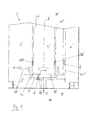
- Fig. 1 shows the state of the art by means of a pump, wherein the construction of the shaft passage with separation means something is shown in more detail in detail.
- the pump which is hereinafter referred to in its entirety by the reference numeral 1 ', generally serves to convey a pumping fluid 2' in the form of a multiphase mixture, ie the multiphase mixture consists of various solid, liquid and gaseous constituents.
- the ingredients are essentially sand and gas which are present as an impurity in the pumping fluid 2 'in intolerable amounts.
- the pumping fluid 2 ' here is petroleum, which under an inlet pressure at a low pressure side LP' of the pump 1 'is ready and in the operating state by means of a in a pump stator (not shown) about a rotation axis A' according to the arrow P rotatably mounted pump rotor (not shown ) is conveyed to a high pressure side HP 'of the pump 1'.
- the pump rotor is designed in such a way and arranged over a rotor shaft 5 'in a shaft passage 6' that between the rotor shaft 5 'and the shaft passage 6' in an annular gap 21 ', a lubricating film of a formed from the pumping fluid 2' lubricating fluid 200 'can be formed ,
- a separation device 7' is provided, with which in the operating state to provide the lubricating fluid 200 'a predetermined amount of the ingredient by means of a centrifugal force from the pumping fluid 2' is separable.
- Fig. 1 shown schematically is for supplying the constituent comprehensive pumping fluid 2 ', so here the petroleum, the separation device 7', which is configured as a with the rotor shaft 5 'of the pump 1' with screws 70 'screwed separation disc, via a feed line with the High pressure side HP 'of the pump 1' connected.
- the separation disk is covered by a cover D 'through which the pumping fluid 2' is fed to the separation disk.
- the separation disc of Fig. 1 shows in detail, with the rotor shaft 5 'about the rotation axis A' co-rotating separation disc an annular chamber, wherein at the annular chamber for the deposition of the ingredients at least one substantially tangentially oriented separation opening is provided.
- the separation opening is for discharging separated ingredient, so in the present example for discharging the enriched in oil sand, via a Abscheidetechnisch 721 'with the low pressure side LP' of the pump 1 'is connected.
- the sand has a higher density than the lubricating fluid 200 'which is finally used to lubricate the rotor shaft 5'.
- the annular gap 21' is fluidly connected to the separation device 7 'by means of a lubricant opening 22' in such a way that the lubricating fluid 200 ', at least partially freed from the sand, reaches the annular gap 21 'for lubricating the shaft passage 6' via the lubricant opening 22 'can be fed.
- a lubricant line 10 ' is additionally provided such that a predeterminable amount of lubricating fluid 200' can be discharged from the separation disk, in particular for feeding additional lubrication point of the pump 1 ', which additional lubricant locations are not explicitly shown for reasons of clarity.
- the lubricating fluid 200 'branched off via the lubricant line 10' is used for lubricating other parts of the system which lie outside the pump 1 'or are not part of the pump 1'.
- the separation device 7 ' in this case the separation disk, is detachably connected to the rotor shaft 5', but it is also possible that the separation device 7 'is an integral part of the rotor shaft 5', and the separation device 7 'in particular with the rotor shaft 5 'integrally connected separation disc.
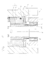
- the inventive pump is very general and in particular in the specific embodiment of the Fig. 2 and Fig. 3 the promotion of a pumping fluid in the form of a multi-phase mixture.
- the pump which is hereinafter referred to in its entirety by the reference numeral 1, is used in general Promotion of a pumping fluid 2 in the form of a multi-phase mixture, ie the pumping fluid consists of various solid, liquid and gaseous ingredients.
- the ingredients are essentially sand and gas which are present as an impurity in the pumping fluid 2 in intolerable amounts.
- the pumping fluid 2 for example, oil
- the pumping fluid 2 which is available under an inlet pressure at a low pressure side LP of the pump 1 and in the operating state by means of a rotatably mounted in a pump stator 3 about a rotation axis A according to the arrow P pump rotor 4 is conveyed to a high pressure side HP of the pump, and a rotor shaft 5 is arranged in such a shaft bushing 6, that between the rotor shaft 5 and the shaft passage 6 in an annular gap 21, a lubricating film of a lubricating fluid 200 formed from the pumping fluid 2 can be formed.
- a separation device 7 is provided on the rotor shaft 5, with which in the operating state for providing the lubricating fluid 200 at the annular gap 21 a predeterminable amount of an ingredient by means of a centrifugal force from the pumping fluid 2 is separable.
- a recirculation device 8 is provided so that a gas 201 can be recirculated with the aid of the separation device 7.
- the shaft passage 6 comprises a stationary sleeve 9 and a rotating shaft sleeve 10.
- the annular gap 21 is, as in the present embodiment, both between the stationary sleeve 9 and the rotating shaft sleeve 10 can be formed, as well as directly between the rotor shaft 5 and shaft passage 6 trainable.
- the in Fig. 2 illustrated recirculation device 8 a feed line 81, a recirculation line 82 and a means for pressure increase 83, in particular a screw conveyor and / or a corrugated pipe.
- the recirculation device 8 is fluidly connected to the high-pressure side HP of the pump by means of the supply line 81, so that the pumping fluid 2 flows from the high-pressure side HP of the pump to the recirculation device 8.
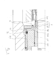
- the separation device 7 or the separation disk which rotates about the rotation axis A with the rotor shaft 5, comprises in detail an annular chamber to which annular chamber for deposition of the ingredient a preferably tangentially oriented separation opening is provided.
- the separation device 7 or separation disc for separating the gas 201 comprises a first separation opening 71 and / or for depositing an ingredient, a second separation opening 72 and / or for depositing the lubricating fluid, a third separation opening 73.
- the first separation opening 71 is flow-connected to the recirculation device 8 and / or recirculation line 82 for separating the gas 201.
- recirculation device 8 is fluidly connected by means of the recirculation line 82 to the high pressure side HP of the pump and / or a Gassenke.
- the pressure increase means 83 are required to generate a pressure in the recirculation line 82 which is higher than the high pressure side HP of the pump and / or the gas bank, so that the gas 201 from the recirculation device 8 to the high pressure side HP of the pump and / or the Gassenke is transportable.
- the recirculation device 8 is formed as an integral part in the pump stator 3, although it is also possible for the recirculation device 8 to be an external recirculation device 8 that is detachably connected to the pump.
- the annular gap 21 is fluidly connected to the third separation opening 73 of the separation device 7 by means of a lubricant opening 22, such that the lubricant fluid 200 at least partially freed from the content reaches the annular gap 21 for lubricating the shaft passage 6 via the lubricant opening 22 can be fed.
- a lubricant line is additionally provided such that a predeterminable amount of lubricating fluid 200 can be discharged from the separation disk, in particular for feeding further lubrication point of the pump 1, which additional lubricant points are not explicitly shown for reasons of clarity.
- the branched off via the lubricant line lubricating fluid 200 is used for lubrication of other parts of the system, which lie outside the pump 1 and are not part of the pump 1.
- the second separation opening 72 is connected to the discharge of separated ingredient, so in the present example for discharging the enriched in oil sand, via a Abscheidetechnisch 721 with the low pressure side LP of the pump 1.
- the sand has a higher density than the lubricating fluid 200 which is used for the lubrication of the rotor shaft 5.
- the Abscheidetechnisch 721 is formed as an integral part of the shaft passage 6 or the pump stator 3, but can also be performed as a separate additional Abscheide effet 721, for example, outside the housing of the pump.
- a second throttle point 74 is provided, which serves to increase the resistance in order to avoid a direct outflow of the pumping fluid 2.
Abstract
Description
Die Erfindung betrifft eine Pumpe zur Förderung eines Pumpfluids in Form eines Mehrphasengemischs sowie eine Rezirkulationseinrichtung für eine Pumpe gemäss dem Oberbegriff der unabhängigen Ansprüche 1 und 15.The invention relates to a pump for conveying a pumping fluid in the form of a multiphase mixture and to a recirculation device for a pump according to the preamble of the independent claims 1 and 15.
Im Stand der Technik ist es eine wohlbekannte Massnahme, Inhaltsstoffe des Pumpfluids mittels der rotierenden Teile von Pumpen zu separieren und die Pumpe oder Drosselungen, also ringförmige Dichtungen, mit dem separierten Medium selbst zu schmieren, was den offensichtlichen Vorteil hat, dass dann für diese Schmieranwendungen kein spezielles Schmiermittel zur Verfügung gestellt werden muss. Das kann vor allem dann von besonderem Vorteil sein, wenn die Bereitstellung des Schmiermittels, z.B. zur Schmierung einer einen Pumpenrotor tragenden rotierenden Rotorwelle der Pumpe, nur unter besonderen Schwierigkeiten möglich ist. Ein weiterer Vorteil besteht darin, dass auf der Nichtantriebsseite durch den Einsatz eines selbstschmierenden bzw. produktgeschmierten Lagers auf eine Wellendichtung verzichtet werden kann, da die Welle nicht mehr zur Atmosphäre herausgeführt werden muss. Als prominente Beispiele sind neben einer Vielzahl weiterer Anwendungen Pumpen zur Förderung von Mehrphasengemischen, wie beispielsweise zur Förderung von Rohöl zu nennen. Solche Pumpen müssen häufig an sehr schlecht zugänglichen Orten betrieben werden, oft viele hundert Meter, sogar bis zu einigen tausend Metern unter der Meeresoberfläche, wo die Pumpen unter extremen Bedingungen über beträchtliche Zeiträume zuverlässig betrieben werden müssen.In the prior art, it is a well-known measure to separate ingredients of the pumping fluid by means of the rotating parts of pumps and to lubricate the pump or throttles, ie annular seals, with the separated medium itself, which has the obvious advantage that then for these lubricating applications no special lubricant needs to be provided. This may be of particular advantage especially if the provision of the lubricant, for example for the lubrication of a rotary rotor shaft of the pump carrying a pump rotor, is possible only with particular difficulty. Another advantage is that it is possible to dispense with a shaft seal on the non-drive side through the use of a self-lubricating or product-lubricated bearing, since the shaft no longer has to be led out to the atmosphere. Prominent examples include a variety of other applications pumps for the promotion of multi-phase mixtures, such as to promote crude oil. Such pumps often need to be operated in very inaccessible locations, often many hundreds of meters, even up to a few thousand meters below the sea surface where the pumps are must be operated reliably under extreme conditions for considerable periods of time.
Ein bisher nur unzureichend gelöstes Problem tritt jedoch bei der Förderung solcher Pumpmedien, wie beispielweise bei einem Mehrphasengemisch auf, das neben Erdöl auch Erdgas und häufig auch Wasser und vor allem schädliche Feststoffanteile wie z.B. Sand enthält. Die zusätzlichen Inhaltsstoffe sind nämlich häufig für die Schmieranwendung eher schädlich. So versteht der Fachmann sofort, dass beispielsweise vor allem harte Inhaltsstoffe wie Sand die Schmierung massiv negativ beeinflussen können. Wird beispielweise ein mit Sand verunreinigtes Schmiermittel zur Schmierung einer Rotorwelle eines Pumpenrads verwendet, so kann der Sand im Schmiermittel beträchtliche Schäden an den zu schmierenden Teilen verursachen, weil die harten Sandkörner die Oberflächen der zu schmierenden Komponenten, die häufig aus verhältnismässig weichem Metall sind, beschädigen können, was letztlich zum Ausfall der Pumpe führen kann.However, a problem that has been solved only insufficiently occurs in the promotion of such pumping media, such as in a multi-phase mixture, which in addition to petroleum, natural gas and often water and especially harmful solid components such. Contains sand. The additional ingredients are often harmful to the lubrication application. So the expert understands immediately that, for example, especially hard ingredients such as sand can affect the lubrication massive negative. For example, if a lubricant contaminated with sand is used to lubricate a rotor shaft of an impeller, the sand in the lubricant can cause considerable damage to the parts to be lubricated, because the hard sand grains damage the surfaces of the components to be lubricated, which are often made of relatively soft metal which can eventually lead to failure of the pump.
Daher ist es im Stand der Technik bekannt, solche Teile die geschmiert werden, beispielsweise mit einem mit Sand verunreinigten Schmiermittel, besonders zu härten, damit der im Schmiermittel enthaltene Sand die Oberflächen nicht beschädigen kann, bzw. um den Verschleiss der entsprechenden Teile zumindest soweit zu reduzieren, dass vertretbar lange Standzeiten, also wirtschaftlich vertretbare Wartungsintervalle erreicht werden können.Therefore, it is known in the prior art, such parts to be lubricated, for example, with a sand-contaminated lubricant, especially to harden so that the sand contained in the lubricant can not damage the surfaces, or at least as far as the wear of the corresponding parts reduce, that reasonably long service life, so economically reasonable maintenance intervals can be achieved.
Dabei ist das Härten der entsprechenden Teile, z.B. der Rotorwelle eines Laufrades der Pumpe bzw. der das Rotorwellenlager bilden statischen oder rotierenden Gegenparte und Lagerkomponenten natürlich eine Massnahme, die einerseits sehr aufwändig und damit teuer ist und letztlich das Problem nicht tatsächlich löst, weil selbst die gehärteten Teile mit der Zeit der reibenden Belastung, z.B. durch im Schmiermittel enthaltenen Sand, nicht auf Dauer standhalten können. Ein weiterer Punkt ist, dass auch beispielweise die Breite der Schmiermittelspalte zwischen den rotierenden und / oder statischen Teilen der Lager oft nicht auf das wünschenswerte Mass verkleinert werden können, weil ansonsten der schädliche Einfluss von harten, nicht kompressiblen Inhaltsstoffen wie Sand so gross würde, dass ein vorzeitiger Verschleiss der entsprechenden Lager unausweichlich würde. Dadurch, dass die Lagerspalte durch derartige Restriktionen nicht optimal einstellbar sind, kann die Laufruhe der gelagerten Teile negativ beeinflusst werden, und durch nicht optimal eingestellte Schmiermittelspalte können schädliche Schwingungen im Betriebszustand auftreten, was letztlich ebenfalls zu einem vorzeitigen Verschleiss führen kann.In this case, the hardening of the corresponding parts, such as the rotor shaft of an impeller of the pump or the rotor shaft bearing form static or rotating counterpart and bearing components, of course, a measure that is on the one hand very complex and therefore expensive and ultimately does not solve the problem actually because even Hardened parts with time of rubbing load, for example by sand contained in the lubricant, can not withstand long term. Another point is that, for example, the The width of the lubricant gaps between the rotating and / or static parts of the bearings often can not be reduced to the desirable level, because otherwise the harmful influence of hard, non-compressible ingredients such as sand would be so large that premature wear of the corresponding bearing would be inevitable. The fact that the bearing gaps are not optimally adjustable by such restrictions, the smoothness of the stored parts can be adversely affected, and not optimally adjusted lubricant gaps can cause harmful vibrations in the operating state, which ultimately can also lead to premature wear.
Eine weitere aus der
Nachteil der beschriebenen Vorrichtung ist, dass lediglich feste oder flüssige Inhaltsstoffe abgeschieden werden können, obwohl auch gasförmige Inhaltsstoffe das Schmierverhalten des Schmiermittels negativ beeinflussen, weil beispielweise die Viskosität, also die Zähigkeit des als Schmiermittel verwendeten Pumpfluids für die Anwendung als Schmiermittel schlecht oder gar nicht geeignet ist.Disadvantage of the device described is that only solid or liquid ingredients can be deposited, although gaseous ingredients adversely affect the lubricating behavior of the lubricant, because, for example, the viscosity, ie the viscosity of the pump fluid used as a lubricant for use as a lubricant poorly or not at all suitable is.
Aufgabe der Erfindung ist es daher, eine Pumpe zur Förderung eines Pumpfluids in Form eines Mehrphasengemischs vorzuschlagen, bei welcher das Pumpfluid gleichzeitig zur Schmierung rotierender Teile der Pumpe, insbesondere zur Schmierung der Rotorwelle des Pumpenrotors verwendet werden kann, wobei die aus dem Stand der Technik bekannten schädlichen Einflüsse der Inhaltsstoffe auf den Schmiervorgang weitestgehend vermieden werden.The object of the invention is therefore to propose a pump for delivering a pumping fluid in the form of a multiphase mixture, wherein the pumping fluid can be used simultaneously for lubricating rotating parts of the pump, in particular for lubricating the rotor shaft of the pump rotor, wherein the known from the prior art harmful influences of the ingredients on the lubrication process are largely avoided.
Die diese Aufgabe lösenden Gegenstände der Erfindung sind durch die Merkmale der unabhängigen Ansprüche 1 und 14 gekennzeichnet.The objects of the invention that solve this object are characterized by the features of independent claims 1 and 14.
Die abhängigen Ansprüche beziehen sich auf besonders vorteilhafte Ausführungsformen der Erfindung.The dependent claims relate to particularly advantageous embodiments of the invention.
Die Erfindung betrifft somit eine Pumpe zur Förderung eines Pumpfluids inThe invention thus relates to a pump for delivering a pumping fluid in
Form eines Mehrphasengemischs, wobei im Betriebszustand das unter einem Eingangsdruck an einer Niederdruckseite der Pumpe bereitgestellte Pumpfluid mittels einem in einem Pumpenstator um eine Drehachse drehbar gelagerten Pumpenrotor auf eine Hochdruckseite der Pumpe beförderbar ist, und eine Rotorwelle derart in einem Wellendurchführung angeordnet ist, dass zwischen der Rotorwelle und dem Wellendurchführung in einem Ringspalt ein Schmierfilm aus einem aus dem Pumpfluid gebildeten Schmierfluid ausbildbar ist, und an der Rotorwelle eine Separationseinrichtung vorgesehen ist, mit welcher im Betriebszustand zur Bereitstellung des Schmierfluids am Ringspalt eine vorgebbare Menge eines Inhaltsstoffs mittels einer Zentrifugalkraft aus dem Pumpfluid separierbar ist. Erfindungsgemäss ist eine Rezirkulationseinrichtung vorgesehen ist, sodass ein Gas mit Hilfe der Separationseinrichtung rezirkulierbar ist.Form of a multi-phase mixture, wherein in the operating state provided under an input pressure at a low pressure side of the pump pump fluid is conveyed by means of a rotatably mounted in a pump stator about a rotation axis pump rotor to a high pressure side of the pump, and a rotor shaft is arranged in such a shaft passage that between the Rotor shaft and the shaft passage in an annular gap, a lubricant film from a fluid formed from the pumping fluid can be formed, and on the rotor shaft, a separation device is provided, with which in the operating state to provide the lubricating fluid at the annular gap a predetermined amount of an ingredient by means of a centrifugal force separated from the pumping fluid is. According to the invention, a recirculation device is provided so that a gas can be recirculated with the aid of the separation device.
Wesentlich für die Erfindung ist es somit, dass eine Rezirkulationseinrichtung vorgesehen ist, mit welcher im Betriebszustand eine vorgebbare Menge eines Gases, in der Praxis häufig Erdgas, rezirkulierbar ist. Das Gas, welches aus dem Pumpfluid separierbar ist, wird im Wesentlichen mit Hilfe der Separationseinrichtung und insbesondere mittels der in der Separationseinrichtung wirkenden Zentrifugalkraft aus dem Pumpfluid separiert. Dazu kann das durch die Pumpe zu fördernde Pumpfluid ein Mehrphasengemisch sein, das mit Sand beladenes Rohöl und Erdgas umfasst, und das beispielsweise aus einer Rohquelle durch die Pumpe in ein Sammellager gefördert wird. Das Pumpfluid ist dabei in der rotierenden Separationseinrichtung den dort aufgrund der Rotation wirkenden Zentrifugalkräften ausgesetzt. Aufgrund der höheren Dichte des Sandes im Vergleich zum flüssigen und gasförmigen Anteil des Pumpfluids, wobei die gasförmigen Anteile wiederum eine geringere Dichte als die flüssigen Anteile aufweisen, reichern sich dabei der Sand unter Wirkung der Zentrifugalkraft am äusseren Rand, die flüssigen Anteile in der Mitte und die gasförmigen Anteile im Inneren, zum Beispiel in einer Ringkammer der Separationseinrichtung, an. Eine weitere Ursache für die Separation des Gases aus dem Pumpfluid ist beispielsweise der Druckunterschied zwischen der Rezirkulationseinrichtung und der Hochdruckseite der Pumpe. Hierbei strömt das Pumpfluid von der Hochdruckseite der Pumpe zur Rezirkulationseinrichtung, also in Richtung einer Gassenke, wo das Gas aus dem Pumpfluid separiert wird und von dort in eine bestimmte Richtung, bevorzugt in Richtung der Hochdruckseite der Pumpe, wieder abströmt.It is thus essential for the invention that a recirculation device is provided, with which a specifiable amount of a gas, in practice frequently natural gas, can be recirculated in the operating state. The gas, which is separable from the pumping fluid, is essentially separated from the pumping fluid by means of the separation device and in particular by means of the centrifugal force acting in the separation device. For this purpose, the pumping fluid to be pumped by the pump may be a multiphase mixture comprising crude oil loaded with sand and natural gas, which is conveyed from a raw source through the pump into a collective storage, for example. The pumping fluid is in the rotating separation device acting there due to the rotation Subjected to centrifugal forces. Due to the higher density of the sand compared to the liquid and gaseous portion of the pumping fluid, wherein the gaseous fractions in turn have a lower density than the liquid portions, accumulate the sand under the effect of centrifugal force at the outer edge, the liquid fractions in the middle and the gaseous components in the interior, for example in an annular chamber of the separation device on. Another cause for the separation of the gas from the pumping fluid is, for example, the pressure difference between the recirculation device and the high pressure side of the pump. In this case, the pumping fluid flows from the high-pressure side of the pump to the recirculation device, ie in the direction of a gas bank, where the gas is separated from the pumping fluid and from there flows in a certain direction, preferably in the direction of the high-pressure side of the pump.
Dadurch bildet sich im Inneren der Ringkammer eine mit Gas hoch angereicherte Phase des Pumpfluids aus, die mittels einer erfindungsgemässen Rezirkulationseinrichtung bevorzugt zurück auf die Hochdruckseite der Pumpe abgeführt wird und nicht mit Gas angereichertes Pumpfluid für die Schmierung, z.B. der Rotorwelle, verwendet wird. Die Entnahme des Schmierfluids, das für die Schmierung verwendet werden soll, erfolgt dabei an einem weiter aussen gelegenen Durchmesser der Ringkammer der Separationseinrichtung, wo sich eine Phase des Pumpfluids mit niedriger Gas- und Sandkonzentration angesammelt hat. Eine mit Sand hoch angereicherte Phase des Pumpfluids bildet sich am äusseren Rand der Ringkammer der Separationseinrichtung aus und wird von dort über eine entsprechende Abscheideleitung bevorzugt zurück auf die Niederdruckseite der Pumpe abgeführt wird und nicht für die Schmierung, z.B. der Rotorwelle, verwendet.As a result, a highly enriched in gas phase of the pumping fluid is formed in the interior of the annular chamber, which is preferably discharged by means of a recirculation device according to the invention back to the high pressure side of the pump and non-gas enriched pumping fluid for lubrication, e.g. the rotor shaft is used. The removal of the lubricating fluid to be used for the lubrication, takes place at a further outward diameter of the annular chamber of the separation device, where a phase of the pumping fluid has accumulated with low gas and sand concentration. A highly enriched with sand phase of the pumping fluid forms at the outer edge of the annular chamber of the separation device and is discharged from there via a corresponding Abscheideleitung preferably back to the low pressure side of the pump and not for lubrication, e.g. the rotor shaft used.
Es versteht sich von selbst, dass auf diese Weise beliebige Inhaltsstoffe des Pumpfluids, die entsprechende Dichteunterschiede aufweisen, mit der Separationseinrichtung separieren lassen und die gasförmigen Anteile mit der Rezirkulationseinrichtung bevorzugt auf die Hochdruckseite rezirkuliert werden, so dass zum Beispiel der Anteil des Pumpfluids, der zum schmieren verwendet werden soll, eine vorbestimmte geeignete Viskosität hat, die nicht zu hoch oder zu niedrig ist, weil gasförmige Anteile mit der Rezirkulationseinrichtung und mit Hilfe der Separationseinrichtung entfernbar sind.It goes without saying that can be separated in this way any ingredients of the pumping fluid having the corresponding density differences with the separation device and the gaseous components with the Recirculation means are preferably recirculated to the high pressure side, so that for example the proportion of the pumping fluid to be used for lubrication, has a predetermined suitable viscosity, which is not too high or too low, because gaseous components with the recirculation means and with the aid of the separation device are removable.
Somit ist es durch die vorliegende Erfindung erstmals möglich, nicht nur feste oder flüssige Inhaltsstoffe sondern auch gasförmige Inhaltsstoffe, die das Schmierverhalten negativ beeinflussen, so von dem zu fördernden Pumpfluid abzuseparieren und mittels der Rezirkulationseinrichtung zu rezirkulieren, das eine von Inhaltsstoffen in ausreichendem Masse gereinigte Phase des Pumpfluids bereitgestellt wird, die zur Schmierung rotierender Teile der Pumpe verwendet werden kann, wobei die aus dem Stand der Technik bekannten schädlichen Einflüsse der Inhaltsstoffe auf den Schmiervorgang weitestgehend vermieden werden. Dabei können, je nach genauer Zusammensetzung und Konsistent des Pumpfluids bzw. der Inhaltsstoffe, auch zum Beispiel Mischungs- oder Lösungsphänomene relevant sein, die den Prozess der Rezirkulation weiter positiv beeinflussen. So ist es zum Beispiel möglich, dass Gasanteile in höher Viskosen und / oder in fluiden Bestandteilen höherer Dichte gelöst oder zum Beispiel in Form von Blasen eingeschlossen sind und so durch die erfindungsgemässe Rezirkulationseinrichtung ebenfalls mit absepariert und rezirkuliert werden. Selbstverständlich können auch andere an sich bekannte Prozesse dazu beitragen, dass über die Rezirkulationseinrichtung nicht nur Bestandteile geringerer Dichte sondern auch solche mit höhere Dichte abscheidbar sind, weil sie durch die Bestandteile höherer Dichte mitgenommen werden.Thus, it is possible for the first time by the present invention, not only solid or liquid ingredients but also gaseous ingredients that adversely affect the lubrication behavior, so abzuseparieren of the pumping fluid to be pumped and recirculate by means of the recirculation, the one of ingredients sufficiently purified phase the pumping fluid is provided, which can be used for lubrication of rotating parts of the pump, wherein the well-known from the prior art harmful influences of the ingredients are minimized to the lubrication process. In this case, depending on the precise composition and consistency of the pumping fluid or the ingredients, also, for example, mixing or solution phenomena may be relevant, which further positively influence the process of recirculation. Thus, it is possible, for example, that gas fractions are dissolved in higher viscoses and / or in higher density fluid constituents or are enclosed, for example, in the form of bubbles and thus likewise separated off and recirculated by the recirculation device according to the invention. Of course, other processes known per se can contribute to the fact that not only components of lower density but also those of higher density can be deposited via the recirculation device, because they are entrained by the components of higher density.
Als besondere Massnahme bildet die Wellendurchführung ein Wellenlager und umfasst eine stationäre Buchse und eine drehende Wellenhülse, wobei der Ringspalt zwischen der stationären Buchse und der drehenden Wellenhülse ausbildbar ist. Im Speziellen bildet die Wellendurchführung vorteilhaft eine Drosselstelle.As a special measure, the shaft passage forms a shaft bearing and comprises a stationary bushing and a rotating shaft sleeve, wherein the annular gap between the stationary bushing and the rotating Shaft sleeve is formed. In particular, the shaft passage advantageously forms a throttle point.
Vorteil dieser Massnahme ist, dass die Drosselstellen, also ringförmige Dichtungen, welche zur Trennung von Druckstufen dienen, ständig den Rotor schmieren und stabilisieren und der Druckseparation dienen, sodass der Rotor während seiner umlaufenden Bewegung ständig nur mit Flüssigkeit geschmiert wird.The advantage of this measure is that the throttle points, ie annular seals, which serve to separate pressure stages, constantly lubricate and stabilize the rotor and serve the pressure separation, so that the rotor is constantly lubricated during its circulating movement only with liquid.
Die Rezirkulationseinrichtung umfasst eine Zuführleitung, eine Rezirkulationsleitung und ein Mittel zur Druckerhöhung, insbesondere eine Förderschnecke und / oder eine geriffelte Leitung. In einem für die Praxis besonders bevorzugten Ausführungsbeispiel befinden sich beispielsweise die Mittel zur Druckerhöhung in der Rezirkulationsleitung, d.h. die Leitung ist innen teilweise oder vollständig geriffelt und / oder hat eine Förderschnecke, sodass, wie der Fachmann sofort versteht, der Druck in der Rezirkulationsleitung, ähnlich dem Effekt einer Drossel, über den Druck der Hochdruckseite der Pumpe bzw. einer Gassenke erhöht wird. Ausserdem ist die Rezirkulationseinrichtung zur Zuführung des Pumpfluids in die Rezirkulationseinrichtung mittels einer Zuführleitung mit der Hochdruckseite der Pumpe strömungsverbunden, sodass das Pumpfluid im Betriebszustand von der Hochdruckseite der Pumpe zur Rezirkulationseinrichtung strömt. Zur Rezirkulation des Gases ist die Rezirkulationseinrichtung über eine Rezirkulationsleitung mit der Hochdruckseite der Pumpe und / oder einer Gassenke strömungsverbunden. Die Rezirkulationsleitung ist dabei derart ausgestaltet, dass mittels der Mittel zur Druckerhöhung ein Druck in der Rezirkulationsleitung höher als auf der Hochdruckseite der Pumpe und / oder der Gassenke herstellbar ist und das Gas von der Rezirkulationseinrichtung auf die Hochdruckseite und / oder die Gassenke beförderbar ist, wobei unter der Gassenke beispielsweise ein Bereich zum sammeln des Gases, ein Gassammelbehälter, oder eine Leitung, die das Gas in einen Bereich ausserhalb der Pumpe leitet, zu verstehen ist.The recirculation device comprises a supply line, a recirculation line and a means for increasing the pressure, in particular a screw conveyor and / or a corrugated line. In a particularly preferred embodiment for practice, for example, the means for pressure increase in the recirculation line, ie the line is inside partially or completely fluted and / or has a screw conveyor, so, as the skilled artisan immediately understands, the pressure in the recirculation line, similar the effect of a throttle, is increased above the pressure of the high pressure side of the pump or a Gassenke. In addition, the recirculation means for supplying the pumping fluid into the recirculation means by means of a supply line to the high pressure side of the pump is fluidly connected, so that the pumping fluid flows in the operating state of the high pressure side of the pump to the recirculation device. For recirculation of the gas, the recirculation device is flow-connected via a recirculation line to the high-pressure side of the pump and / or a gas bank. The recirculation line is designed such that by means of the means for pressure increase, a pressure in the recirculation line higher than on the high pressure side of the pump and / or Gassenke can be produced and the gas from the recirculation device to the high pressure side and / or the Gassenke is conveyed, said for example, an area for collecting the gas, a gas collecting container, or a conduit which directs the gas into an area outside the pump is to be understood, for example.
Die Rezirkulationseinrichtung ist dabei als integraler Bestandteil der Pumpen ausgebildet. Die Zuführ- und Rezirkulationsleitung können beispielweise ein integraler Bestandteil, des Pumpengehäuse, insbesondere eine im Pumpengehäuse bzw. Pumpenstator oder Wellendurchführung verlaufende Bohrung oder bohrungsähnliche Verbindungsöffnung sein, oder aber auch durch separate Leitungen realisiert sein, die die Hochdruckseite mit der Rezirkulationseinrichtung und / oder der Separationskammer verbinden.The recirculation device is designed as an integral part of the pump. The supply and recirculation can be, for example, an integral part of the pump housing, in particular a running in the pump housing or pump stator or shaft passage bore or hole-like connection opening, or be realized by separate lines, the high pressure side with the recirculation device and / or the separation chamber connect.
Im Speziellen umfasst die mit der Rotorwelle um die Drehachse mitrotierende Separationseinrichtung eine Ringkammer, an welcher Ringkammer zur Abscheidung des Inhaltsstoffs eine bevorzugt tangential ausgerichtete Abscheideöffnung vorgesehen ist. Als bevorzugte Massnahme umfasst die Separationseinrichtung zur Abscheidung des Gases eine erste Abscheideöffnung und / oder zur Abscheidung eines Inhaltsstoffes eine zweite Abscheideöffnung und / oder zur Abscheidung des Schmierfluids eine dritte Abscheideöffnung. Die erste Abscheideöffnung ist zur Abscheidung des Gases mit der Rezirkulationseinrichtung und / oder der Rezirkulationsleitung strömungsverbunden, sodass, wohingegen die zweite Abscheideöffnung zum Abführen des Inhaltsstoffes mittels einer Abscheideleitung mit der Niederdruckseite der Pumpe strömungsverbunden ist.In particular, the separation device co-rotating with the rotor shaft about the axis of rotation comprises an annular chamber to which annular chamber for deposition of the ingredient a preferably tangentially oriented separation opening is provided. As a preferred measure, the separation device for separating the gas comprises a first separation opening and / or for depositing an ingredient a second separation opening and / or for separating the lubricating fluid a third separation opening. The first separation opening is fluidly connected to the recirculation means and / or the recirculation conduit for separation of the gas, so that while the second separation opening for discharging the ingredient is flow connected to the low pressure side of the pump by means of a separation line.
Da die abzuscheidenden Inhaltsstoffe unterschiedliche Dichten haben, bildet sich im Inneren der Ringkammer der Separationseinrichtung, an der ersten Abscheideöffnung eine mit Gas hoch angereicherte Phase des Pumpfluids aus. Die Entnahme des Schmierfluids, das für die Schmierung verwendet werden soll, erfolgt dabei an der dritten Abscheideöffnung, einem weiter aussen gelegenen Durchmesser der Ringkammer der Separationseinrichtung, wo sich eine Phase des Pumpfluids mit niedriger Gas- und Feststoffkonzentration, beispielsweise Sand, angesammelt hat. Eine mit Sand hoch angereicherte Phase des Pumpfluids bildet sich am äusseren Rand der Ringkammer der Separationseinrichtung aus und wird von dort über die zweite Abscheideöffnung und eine entsprechende Abscheideleitung bevorzugt zurück auf die Niederdruckseite der Pumpe abgeführt wird und nicht für die Schmierung, z.B. der Rotorwelle, verwendet.Since the components to be separated have different densities, a gas-enriched phase of the pumping fluid forms in the interior of the annular chamber of the separation device at the first separation opening. The removal of the lubricating fluid to be used for the lubrication, takes place at the third separation opening, a further outward diameter of the annular chamber of the separation device, where a phase of the pumping fluid with low gas and solid concentration, such as sand, has accumulated. A highly enriched with sand phase of the pumping fluid is formed at the outer edge of the annular chamber of the separation device and is preferred from there via the second separation opening and a corresponding Abscheideleitung is discharged back to the low pressure side of the pump and not used for lubrication, for example, the rotor shaft.
Dabei können selbstverständlich auch die Rezirkulations- und Abscheideleitung integrale Bestandteile des Pumpengehäuses, insbesondere im Pumpengehäuse bzw. Pumpenstator verlaufende Bohrungen oder bohrungsähnliche Verbindungsöffnungen sein, oder aber die Rezirkulations - und Abscheideleitung können auch durch separate Leitungen realisiert sein, die die Abscheideöffnungen der Separationseinrichtung mit der Rezirkulationseinrichtung/-leitung und / oder der Niederdruckseite der Pumpe oder sonstigen Stellen mit niederem Druck verbinden.In this case, of course, the recirculation and Abscheideleitung integral components of the pump housing, in particular in the pump housing or pump stator extending bores or hole-like connection openings, or the recirculation and Abscheideleitung can also be realized by separate lines, the separation of the separation device with the recirculation / line and / or the low-pressure side of the pump or other points with low pressure connect.
Damit beispielsweise das Wellendurchführung, in dem die Rotorwelle der Pumpe gelagert ist, oder der Ringspalt zwischen stationärer Buchse und drehender Wellenhülse, optimal mit der vom Inhaltsstoff gereinigten Phase des Pumpfluids zur Schmierung versorgt werden kann, ist der Ringspalt mittels einer Schmiermittelöffnung derart mit der dritten Abscheideöffnung der Separationseinrichtung strömungsverbunden, dass das von dem Inhaltsstoff zumindest teilweise befreite Schmierfluid dem Ringspalt zur Schmierung der Wellendurchführung über die Schmiermittelöffnung zuführbar ist.Thus, for example, the shaft bushing, in which the rotor shaft of the pump is mounted, or the annular gap between the stationary sleeve and rotating shaft sleeve can be optimally supplied with the cleaned of the ingredient phase of the pumping fluid for lubrication, the annular gap by means of a lubricant opening in such a way with the third separation opening fluidly connected to the separation device, that the lubrication fluid, which is at least partially freed from the ingredient, can be fed to the annular gap for lubrication of the shaft passage via the lubricant opening.
In einer speziellen Ausführungsvariante kann eine zusätzliche Schmiermittelleitung derart vorgesehen sein, dass eine vorgebbare Menge an Schmierfluid von der Separationseinrichtung abführbar ist, insbesondere zur Speisung einer weiteren Schmierstelle der Pumpe verwendet werden kann. Dabei kann selbstverständlich auch die Schmiermittelleitung im Speziellen ein integraler Bestandteil des Pumpengehäuse, insbesondere eine im Pumpengehäuse bzw. Pumpenstator verlaufende Bohrung oder bohrungsähnliche Verbindungsöffnung sein, oder aber die Schmiermittelleitung kann auch durch eine separate Leitung realisiert sein, die die Separationseinrichtung der Separationskammer mit der weiteren Schmierstelle in der Pumpe verbindet.In a specific embodiment, an additional lubricant line can be provided such that a predeterminable amount of lubricating fluid can be discharged from the separation device, in particular can be used to supply a further lubrication point of the pump. In this case, of course, the lubricant line in particular an integral part of the pump housing, in particular a running in the pump housing or pump stator bore or hole-like connection opening, or the lubricant line can also be realized by a separate line, the separation device of the separation chamber with the other lubrication point in the pump connects.
Je nach Anwendung und Ausführungsbeispiel kann die Separationseinrichtung entweder lösbar mit der Rotorwelle verbunden sein, wobei die Separationseinrichtung insbesondere als eine mit der Rotorwelle verschraubbare Separationsscheibe ausgestaltet sein kann. Dabei ist es selbstverständlich auch möglich, dass die Separationseinrichtung ein integraler Bestandteil der Rotorwelle ist, wobei die Separationseinrichtung insbesondere eine mit der Rotorwelle integral verbundene Separationsscheibe sein kann.Depending on the application and exemplary embodiment, the separation device can either be detachably connected to the rotor shaft, wherein the separation device can be designed, in particular, as a separation disk which can be screwed to the rotor shaft. It is of course also possible that the separation device is an integral part of the rotor shaft, wherein the separation device may be in particular a separation disc integrally connected to the rotor shaft.
Die Erfindung betrifft weiter eine Rezirkulationseinrichtung für eine erfindungsgemässe Pumpe.The invention further relates to a recirculation device for a pump according to the invention.
Im Folgenden wird die Erfindung an Hand der Zeichnung näher erläutert. Es zeigen in schematischer Darstellung:
- Fig. 1
- den Stand der Technik am Beispiel einer Pumpe mit Separationsscheibe;
- Fig. 2
- ein Ausführungsbeispiel einer erfindungsgemässe Pumpe mit Rezirkulationseinrichtung;
- Fig. 3
- eine detaillierte Darstellung eines Ausführungsbeispiels einer erfindungsgemässe Pumpe mit Rezirkulationseinrichtung;
- Fig. 1
- the prior art using the example of a pump with separation disc;
- Fig. 2
- an embodiment of an inventive pump with recirculation device;
- Fig. 3
- a detailed illustration of an embodiment of an inventive pump with recirculation device;
Für die folgende Beschreibung der Figuren gilt, dass alle Bezugzeichen, die sich in den Beispielen auf Merkmale aus dem Stand der Technik beziehen mit Hochkomma versehen sind und alle Bezugzeichen, die sich auf Merkmale erfindungsgemässer Ausführungsbeispiele beziehen ohne Hochkomma gekennzeichnet sind.For the following description of the figures, it applies that all reference symbols, which refer to features of the prior art in the examples, are provided with apostrophes and all reference symbols, which refer to features of embodiments according to the invention, are marked without apostrophes.
Wie in
Die Separationsscheibe der
Damit das Schmierfluid 200' zur Schmierung der Rotorwelle 5' in der Wellendurchführung 6' bereitgestellt werden kann, ist der Ringspalt 21' mittels einer Schmiermittelöffnung 22' derart mit der Separationseinrichtung 7' strömungsverbunden, dass das vom Sand zumindest teilweise befreite Schmierfluid 200' dem Ringspalt 21' zur Schmierung der Wellendurchführung 6' über die Schmiermittelöffnung 22' zuführbar ist.In order for the lubricating fluid 200 'to be provided in the shaft passage 6' for lubricating the rotor shaft 5 ', the annular gap 21' is fluidly connected to the separation device 7 'by means of a lubricant opening 22' in such a way that the lubricating fluid 200 ', at least partially freed from the sand, reaches the annular gap 21 'for lubricating the shaft passage 6' via the lubricant opening 22 'can be fed.
Des weiteren ist zusätzlich eine Schmiermittelleitung 10' derart vorgesehen, dass eine vorgebbare Menge an Schmierfluid 200' von der Separationsscheibe abführbar ist, insbesondere zur Speisung von weiteren Schmierstelle der Pumpe 1', welche zusätzlichen Schmiermittelstellen aus Gründen der Übersichtlichkeit nicht explizit dargestellten sind. Dabei wird das über die Schmiermittelleitung 10' abgezweigte Schmierfluid 200' zur Schmierung weiterer Anlagenteile verwendet wird, die ausserhalb der Pumpe 1' liegen bzw. nicht Teil der Pumpe 1' sind.Furthermore, a lubricant line 10 'is additionally provided such that a predeterminable amount of lubricating fluid 200' can be discharged from the separation disk, in particular for feeding additional lubrication point of the pump 1 ', which additional lubricant locations are not explicitly shown for reasons of clarity. In this case, the lubricating fluid 200 'branched off via the lubricant line 10' is used for lubricating other parts of the system which lie outside the pump 1 'or are not part of the pump 1'.
Wie bereits erwähnt, ist die Separationseinrichtung 7', also hier die Separationsscheibe, lösbar mit der Rotorwelle 5' verbunden, allerdings ist es auch möglich, dass die Separationseinrichtung 7' ein integraler Bestandteil der Rotorwelle 5' ist, und die Separationseinrichtung 7' insbesondere eine mit der Rotorwelle 5' integral verbundene Separationsscheibe ist.As already mentioned, the separation device 7 ', in this case the separation disk, is detachably connected to the rotor shaft 5', but it is also possible that the separation device 7 'is an integral part of the rotor shaft 5', and the separation device 7 'in particular with the rotor shaft 5 'integrally connected separation disc.
Die erfindungsgemässe Pumpe dient ganz allgemein und insbesondere im speziellen Ausführungsbeispiel der
Wie in
Ausserdem umfasst die in
Damit das separierte Gas 201 in die Rezirkulationseinrichtung 8 und / oder Rezirkulationsleitung 82 abgeschieden wird, ist die erste Abscheideöffnung 71 zur Abscheidung des Gases 201 mit der Rezirkulationseinrichtung 8 und /oder Rezirkulationsleitung 82 strömungsverbunden. Zur Rezirkulation des Gases 201 ist Rezirkulationseinrichtung 8 mittels die Rezirkulationsleitung 82 mit der Hochdruckseite HP der Pumpe und / oder einer Gassenke strömungsverbunden. Die Mittel zur Druckerhöhung 83 werden dabei benötigt, um einen Druck in der Rezirkulationsleitung 82 zu erzeugen, der höher als auf der Hochdruckseite HP der Pumpe und / oder der Gassenke ist, sodass das Gas 201 von der Rezirkulationseinrichtung 8 auf die Hochdruckseite HP der Pumpe und / oder die Gassenke beförderbar ist. Wie bereits erwähnt, ist die Rezirkulationseinrichtung 8 als integraler Bestandteil im Pumpenstator 3 ausgebildet, allerdings ist es auch möglich, dass die Rezirkulationseinrichtung 8 eine externe, lösbar mit der Pumpe verbundene Rezirkulationseinrichtung 8 ist.In order for the separated
Damit das Schmierfluid 200 zur Schmierung bereitgestellt werden kann, ist der Ringspalt 21 mittels einer Schmiermittelöffnung 22 derart mit der dritten Abscheideöffnung 73 der Separationseinrichtung 7 strömungsverbunden, dass das von dem Inhaltsstoff zumindest teilweise befreite Schmierfluid 200 dem Ringspalt 21 zur Schmierung der Wellendurchführung 6 über die Schmiermittelöffnung 22 zuführbar ist.In order for the lubricating
Des weiteren ist zusätzlich eine Schmiermittelleitung derart vorgesehen, dass eine vorgebbare Menge an Schmierfluid 200 von der Separationsscheibe abführbar ist, insbesondere zur Speisung von weiteren Schmierstelle der Pumpe 1, welche zusätzlichen Schmiermittelstellen aus Gründen der Übersichtlichkeit nicht explizit dargestellten sind. Dabei wird das über die Schmiermittelleitung abgezweigte Schmierfluid 200 zur Schmierung weiterer Anlagenteile verwendet wird, die ausserhalb der Pumpe 1 liegen bzw. nicht Teil der Pumpe 1 sind.Furthermore, a lubricant line is additionally provided such that a predeterminable amount of lubricating fluid 200 can be discharged from the separation disk, in particular for feeding further lubrication point of the pump 1, which additional lubricant points are not explicitly shown for reasons of clarity. In this case, the branched off via the lubricant
Die zweite Abscheideöffnung 72 ist zum Abführen separierten Inhaltsstoffes, also im vorliegenden Beispiel zum Abführen des im Erdöl angereicherten Sandes, über eine Abscheideleitung 721 mit der Niederdruckseite LP der Pumpe 1 verbunden ist. Der Sand hat dabei eine höhere Dichte als das Schmierfluid 200 das zur Schmierung der Rotorwelle 5 verwendet wird.The second separation opening 72 is connected to the discharge of separated ingredient, so in the present example for discharging the enriched in oil sand, via a
Die Abscheideleitung 721 ist als integraler Bestandteil in der Wellendurchführung 6 oder dem Pumpenstator 3 ausgebildet, kann jedoch auch als separate zusätzliche Abscheideleitung 721 zum Beispiel aussen am Gehäuse der Pumpe geführt sein.The
Als vorteilhafte Massnahme ist eine zweite Drosselstelle 74 vorgesehen, die der Erhöhung des Widerstandes dient, um ein direktes Abfliessen des Pumpfluids 2 zu vermeiden.As an advantageous measure, a
Es versteht sich, dass in allen in den Figuren lediglich exemplarisch dargestellten Ausführungsbeispielen der Erfindung nur beispielhaft bzw. exemplarisch zu verstehen sind und die Erfindung insbesondere, aber nicht nur, alle geeigneten Kombinationen der beschriebenen Ausführungsbeispiele umfasst.It is understood that in all the exemplary embodiments of the invention illustrated only by way of example in the figures, by way of example only and by way of example, the invention particularly, but not exclusively, encompasses all suitable combinations of the exemplary embodiments described.
Claims (15)
Priority Applications (3)
| Application Number | Priority Date | Filing Date | Title |
|---|---|---|---|
| EP12176181.1A EP2626563B1 (en) | 2012-02-10 | 2012-07-12 | Pump, recirculating device for a pump and rotor shaft for a pump |
| BR102013003795-8A BR102013003795B1 (en) | 2012-02-10 | 2013-02-08 | PUMP AND RECIRCULATION ASSEMBLY FOR A PUMP |
| US13/763,554 US9683575B2 (en) | 2012-02-10 | 2013-02-08 | Pump as well as a recirculation device for a pump |
Applications Claiming Priority (2)
| Application Number | Priority Date | Filing Date | Title |
|---|---|---|---|
| EP12154903 | 2012-02-10 | ||
| EP12176181.1A EP2626563B1 (en) | 2012-02-10 | 2012-07-12 | Pump, recirculating device for a pump and rotor shaft for a pump |
Publications (3)
| Publication Number | Publication Date |
|---|---|
| EP2626563A2 true EP2626563A2 (en) | 2013-08-14 |
| EP2626563A3 EP2626563A3 (en) | 2018-03-21 |
| EP2626563B1 EP2626563B1 (en) | 2020-06-03 |
Family
ID=46506266
Family Applications (2)
| Application Number | Title | Priority Date | Filing Date |
|---|---|---|---|
| EP12176181.1A Active EP2626563B1 (en) | 2012-02-10 | 2012-07-12 | Pump, recirculating device for a pump and rotor shaft for a pump |
| EP13151407.7A Active EP2626564B1 (en) | 2012-02-10 | 2013-01-16 | Pump, separation device for a pump, and a rotor shaft for a pump |
Family Applications After (1)
| Application Number | Title | Priority Date | Filing Date |
|---|---|---|---|
| EP13151407.7A Active EP2626564B1 (en) | 2012-02-10 | 2013-01-16 | Pump, separation device for a pump, and a rotor shaft for a pump |
Country Status (3)
| Country | Link |
|---|---|
| US (2) | US10082149B2 (en) |
| EP (2) | EP2626563B1 (en) |
| ES (1) | ES2796733T3 (en) |
Cited By (1)
| Publication number | Priority date | Publication date | Assignee | Title |
|---|---|---|---|---|
| EP3623633A1 (en) | 2018-09-17 | 2020-03-18 | Sulzer Management AG | Pump for multiphase fluids |
Families Citing this family (5)
| Publication number | Priority date | Publication date | Assignee | Title |
|---|---|---|---|---|
| EP2901018B1 (en) * | 2012-09-12 | 2021-04-21 | FMC Technologies, Inc. | Subsea multiphase pump or compressor with magnetic coupling and cooling or lubrication by liquid or gas extracted from process fluid |
| WO2014095291A1 (en) * | 2012-12-20 | 2014-06-26 | Sulzer Pumpen Ag | Multiphase pump with separator, wherein the process fluid lubricates and cools the pump |
| RU2716348C2 (en) * | 2018-07-23 | 2020-03-11 | Акционерное общество "Гидрогаз" (АО "Гидрогаз") | Semi-submerged pump with shafting line on plain bearings |
| US11666680B2 (en) * | 2018-08-28 | 2023-06-06 | Aatru Medical, LLC | Dressing |
| NO346033B1 (en) | 2018-12-20 | 2022-01-10 | Fsubsea As | Subsea pump system with process lubricated bearings, related method and use |
Citations (1)
| Publication number | Priority date | Publication date | Assignee | Title |
|---|---|---|---|---|
| EP1215490A2 (en) | 2000-12-18 | 2002-06-19 | Delphi Technologies, Inc. | Slip method for making exhaust sensors |
Family Cites Families (24)
| Publication number | Priority date | Publication date | Assignee | Title |
|---|---|---|---|---|
| US2830755A (en) * | 1955-05-23 | 1958-04-15 | Borg Warner | Rotary compressor |
| CH343727A (en) * | 1957-04-25 | 1959-12-31 | Alsacienne Constr Meca | Device for sealing around a rotating shaft passing through a wall |
| US3203354A (en) * | 1962-03-26 | 1965-08-31 | Thiokol Chemical Corp | Pump |
| USRE26570E (en) * | 1962-11-09 | 1969-04-29 | Method and mechanism for lubricating the shaft elements of a pump rotor for pumping an abradant-containing liquid | |
| JPS403655B1 (en) * | 1962-11-20 | 1965-02-26 | ||
| GB1071266A (en) * | 1963-10-15 | 1967-06-07 | Sigmund Pulsometer Pumps Ltd | Liquid-moving unit comprising a centrifugal pump and an electric driving motor therefor |
| CH557472A (en) * | 1972-09-13 | 1974-12-31 | Sulzer Ag | Rotary pump for delivering superheated media - has bypass for cooling of shaft seals and shaft bearings |
| US3867056A (en) * | 1973-09-27 | 1975-02-18 | Oil Dynamics Inc | Recirculating gas separation means for submersible oil well pumps |
| US4333748A (en) * | 1978-09-05 | 1982-06-08 | Baker International Corporation | Rotary gas/liquid separator |
| US4410337A (en) * | 1980-04-07 | 1983-10-18 | A. Ahlstrom Osakeyhtio | Method and an apparatus for separating a gas from a fibre suspension |
| FI73023C (en) * | 1984-07-17 | 1987-08-10 | Ahlstroem Oy | ANORDINATION FOR AVAILABILITY OF FIBERS AND PENSION. |
| CH672007A5 (en) * | 1985-11-11 | 1989-10-13 | Hermetic Pumpen Gmbh | Vertical pump driven by glandless motor |
| US4811471A (en) * | 1987-11-27 | 1989-03-14 | Carrier Corporation | Method of assembling scroll compressors |
| US4854831A (en) * | 1987-11-27 | 1989-08-08 | Carrier Corporation | Scroll compressor with plural discharge flow paths |
| US4795321A (en) * | 1987-11-27 | 1989-01-03 | Carrier Corporation | Method of lubricating a scroll compressor |
| US4768936A (en) * | 1987-11-27 | 1988-09-06 | Carrier Corporation | Scroll compressor with oil pickup tube in oil sump |
| US4795322A (en) * | 1987-11-27 | 1989-01-03 | Carrier Corporation | Scroll compressor with oil thrust force on orbiting scroll |
| US4871301A (en) * | 1988-02-29 | 1989-10-03 | Ingersoll-Rand Company | Centrifugal pump bearing arrangement |
| KR950006402B1 (en) * | 1990-02-06 | 1995-06-14 | 인거솔-랜드 캄파니 | Centrifugal pump lubricant strainer system |
| US5118466A (en) * | 1990-03-12 | 1992-06-02 | Westinghouse Electric Corp. | Nuclear reactor coolant pump with internal self-cooling arrangement |
| FI95540C (en) * | 1990-09-25 | 1996-02-26 | Ahlstroem Oy | Method and apparatus for separating gas from liquid containing solid material |
| US5248245A (en) * | 1992-11-02 | 1993-09-28 | Ingersoll-Dresser Pump Company | Magnetically coupled centrifugal pump with improved casting and lubrication |
| DE50206223D1 (en) * | 2001-10-22 | 2006-05-18 | Sulzer Pumpen Ag | Shaft sealing arrangement for a pump for conveying hot fluids |
| FI20050733A (en) * | 2005-06-22 | 2006-12-23 | Sulzer Pumpen Ag | Gas separator, its front wall and separator wheels |
-
2012
- 2012-07-12 ES ES12176181T patent/ES2796733T3/en active Active
- 2012-07-12 EP EP12176181.1A patent/EP2626563B1/en active Active
-
2013
- 2013-01-16 EP EP13151407.7A patent/EP2626564B1/en active Active
- 2013-02-08 US US13/763,577 patent/US10082149B2/en active Active
- 2013-02-08 US US13/763,554 patent/US9683575B2/en active Active
Patent Citations (1)
| Publication number | Priority date | Publication date | Assignee | Title |
|---|---|---|---|---|
| EP1215490A2 (en) | 2000-12-18 | 2002-06-19 | Delphi Technologies, Inc. | Slip method for making exhaust sensors |
Cited By (1)
| Publication number | Priority date | Publication date | Assignee | Title |
|---|---|---|---|---|
| EP3623633A1 (en) | 2018-09-17 | 2020-03-18 | Sulzer Management AG | Pump for multiphase fluids |
Also Published As
| Publication number | Publication date |
|---|---|
| US20130209226A1 (en) | 2013-08-15 |
| EP2626564B1 (en) | 2020-12-09 |
| US20130315709A1 (en) | 2013-11-28 |
| US10082149B2 (en) | 2018-09-25 |
| BR102013003215A2 (en) | 2015-07-14 |
| BR102013003795A2 (en) | 2015-06-16 |
| EP2626563A3 (en) | 2018-03-21 |
| ES2796733T3 (en) | 2020-11-30 |
| EP2626564A1 (en) | 2013-08-14 |
| EP2626563B1 (en) | 2020-06-03 |
| US9683575B2 (en) | 2017-06-20 |
Similar Documents
| Publication | Publication Date | Title |
|---|---|---|
| EP2626563B1 (en) | Pump, recirculating device for a pump and rotor shaft for a pump | |
| EP2386767B1 (en) | Helico-axial pump and method for bearing a rotor in a helico-axial pump | |
| WO2009130124A1 (en) | Bearing arrangement having a double-row roller bearing, turbocharger and method for feeding a lubricant to the rows of rolling bodies of a double-row roller bearing | |
| DE60124859T2 (en) | SCREW COMPRESSOR WITH WATER INJECTION | |
| EP2060794B1 (en) | Vacuum pump with lubricant pump | |
| EP0718541A1 (en) | Method and device for self-lubricating of the bearings of a turbo-charger | |
| DE102017109553A1 (en) | COMPRESSOR WITH CONTACT-FREE AND CONTACT SEALS | |
| EP3121450A1 (en) | Pump for conveying a fluid with varying viscosity | |
| EP3094875B1 (en) | Bearing of a rotating shaft with sealing | |
| EP2386766B1 (en) | Helico-axial pump, rotor for same, method for hydrodynamic bearing of a rotor of a helicon-axial pump and a hybrid pump with a rotor for a helico-axial pump | |
| DE3011688A1 (en) | AXIAL SLUDGE PUMP | |
| DE112017001057T5 (en) | SLIDING BZW. RADIAL STORAGE AND ROTATION MACHINE | |
| DE102017114646B4 (en) | Conveyor and compressor element, hollow shaft, internal combustion engine and method for cleaning blow-by gases | |
| DE112013005092B4 (en) | Clutch lubrication | |
| EP1649206B1 (en) | Device for sharing out a viscous medium, especially a lubricant such as oil, transported in a gas flow | |
| DE20311890U1 (en) | Rotary union for minimum quantity lubrication | |
| DE10022901C2 (en) | Mixing device for feeding and dosing a liquid into a sludge suspension | |
| EP0628725A2 (en) | Gear pump | |
| WO2014044416A1 (en) | Multi-stage hydraulic engine | |
| DE2901638C3 (en) | ||
| DE102004030123B3 (en) | Screw pump has casting forming end piece of housing with cavity connecting axial bore to bearing as part of pressure line | |
| EP2525099A1 (en) | Rotary pump with two bearing elements and a flow channel | |
| DE1046423B (en) | Device for withdrawing lubricant from rotating lubricant containers | |
| CH714176A1 (en) | Centrifugal pump for cryogenic fluids. | |
| WO2009024476A1 (en) | Multi-phase pump |
Legal Events
| Date | Code | Title | Description |
|---|---|---|---|
| PUAI | Public reference made under article 153(3) epc to a published international application that has entered the european phase |
Free format text: ORIGINAL CODE: 0009012 |
|
| AK | Designated contracting states |
Kind code of ref document: A2 Designated state(s): AL AT BE BG CH CY CZ DE DK EE ES FI FR GB GR HR HU IE IS IT LI LT LU LV MC MK MT NL NO PL PT RO RS SE SI SK SM TR |
|
| AX | Request for extension of the european patent |
Extension state: BA ME |
|
| RAP1 | Party data changed (applicant data changed or rights of an application transferred) |
Owner name: SULZER MANAGEMENT AG |
|
| PUAL | Search report despatched |
Free format text: ORIGINAL CODE: 0009013 |
|
| AK | Designated contracting states |
Kind code of ref document: A3 Designated state(s): AL AT BE BG CH CY CZ DE DK EE ES FI FR GB GR HR HU IE IS IT LI LT LU LV MC MK MT NL NO PL PT RO RS SE SI SK SM TR |
|
| AX | Request for extension of the european patent |
Extension state: BA ME |
|
| RIC1 | Information provided on ipc code assigned before grant |
Ipc: F04D 7/04 20060101AFI20180210BHEP Ipc: F04D 29/06 20060101ALI20180210BHEP |
|
| STAA | Information on the status of an ep patent application or granted ep patent |
Free format text: STATUS: REQUEST FOR EXAMINATION WAS MADE |
|
| 17P | Request for examination filed |
Effective date: 20180921 |
|
| RBV | Designated contracting states (corrected) |
Designated state(s): AL AT BE BG CH CY CZ DE DK EE ES FI FR GB GR HR HU IE IS IT LI LT LU LV MC MK MT NL NO PL PT RO RS SE SI SK SM TR |
|
| RIC1 | Information provided on ipc code assigned before grant |
Ipc: F04D 7/04 20060101AFI20191206BHEP Ipc: F04D 29/06 20060101ALI20191206BHEP |
|
| GRAP | Despatch of communication of intention to grant a patent |
Free format text: ORIGINAL CODE: EPIDOSNIGR1 |
|
| STAA | Information on the status of an ep patent application or granted ep patent |
Free format text: STATUS: GRANT OF PATENT IS INTENDED |
|
| INTG | Intention to grant announced |
Effective date: 20200130 |
|
| GRAS | Grant fee paid |
Free format text: ORIGINAL CODE: EPIDOSNIGR3 |
|
| GRAA | (expected) grant |
Free format text: ORIGINAL CODE: 0009210 |
|
| STAA | Information on the status of an ep patent application or granted ep patent |
Free format text: STATUS: THE PATENT HAS BEEN GRANTED |
|
| AK | Designated contracting states |
Kind code of ref document: B1 Designated state(s): AL AT BE BG CH CY CZ DE DK EE ES FI FR GB GR HR HU IE IS IT LI LT LU LV MC MK MT NL NO PL PT RO RS SE SI SK SM TR |
|
| REG | Reference to a national code |
Ref country code: GB Ref legal event code: FG4D Free format text: NOT ENGLISH |
|
| REG | Reference to a national code |
Ref country code: CH Ref legal event code: EP Ref country code: AT Ref legal event code: REF Ref document number: 1277283 Country of ref document: AT Kind code of ref document: T Effective date: 20200615 |
|
| REG | Reference to a national code |
Ref country code: DE Ref legal event code: R096 Ref document number: 502012016112 Country of ref document: DE |
|
| REG | Reference to a national code |
Ref country code: LT Ref legal event code: MG4D Ref country code: NO Ref legal event code: T2 Effective date: 20200603 |
|
| PG25 | Lapsed in a contracting state [announced via postgrant information from national office to epo] |
Ref country code: SE Free format text: LAPSE BECAUSE OF FAILURE TO SUBMIT A TRANSLATION OF THE DESCRIPTION OR TO PAY THE FEE WITHIN THE PRESCRIBED TIME-LIMIT Effective date: 20200603 Ref country code: LT Free format text: LAPSE BECAUSE OF FAILURE TO SUBMIT A TRANSLATION OF THE DESCRIPTION OR TO PAY THE FEE WITHIN THE PRESCRIBED TIME-LIMIT Effective date: 20200603 Ref country code: GR Free format text: LAPSE BECAUSE OF FAILURE TO SUBMIT A TRANSLATION OF THE DESCRIPTION OR TO PAY THE FEE WITHIN THE PRESCRIBED TIME-LIMIT Effective date: 20200904 Ref country code: FI Free format text: LAPSE BECAUSE OF FAILURE TO SUBMIT A TRANSLATION OF THE DESCRIPTION OR TO PAY THE FEE WITHIN THE PRESCRIBED TIME-LIMIT Effective date: 20200603 |
|
| REG | Reference to a national code |
Ref country code: NL Ref legal event code: MP Effective date: 20200603 |
|
| PG25 | Lapsed in a contracting state [announced via postgrant information from national office to epo] |
Ref country code: LV Free format text: LAPSE BECAUSE OF FAILURE TO SUBMIT A TRANSLATION OF THE DESCRIPTION OR TO PAY THE FEE WITHIN THE PRESCRIBED TIME-LIMIT Effective date: 20200603 Ref country code: HR Free format text: LAPSE BECAUSE OF FAILURE TO SUBMIT A TRANSLATION OF THE DESCRIPTION OR TO PAY THE FEE WITHIN THE PRESCRIBED TIME-LIMIT Effective date: 20200603 Ref country code: RS Free format text: LAPSE BECAUSE OF FAILURE TO SUBMIT A TRANSLATION OF THE DESCRIPTION OR TO PAY THE FEE WITHIN THE PRESCRIBED TIME-LIMIT Effective date: 20200603 Ref country code: BG Free format text: LAPSE BECAUSE OF FAILURE TO SUBMIT A TRANSLATION OF THE DESCRIPTION OR TO PAY THE FEE WITHIN THE PRESCRIBED TIME-LIMIT Effective date: 20200903 |
|
| REG | Reference to a national code |
Ref country code: ES Ref legal event code: FG2A Ref document number: 2796733 Country of ref document: ES Kind code of ref document: T3 Effective date: 20201130 |
|
| PG25 | Lapsed in a contracting state [announced via postgrant information from national office to epo] |
Ref country code: NL Free format text: LAPSE BECAUSE OF FAILURE TO SUBMIT A TRANSLATION OF THE DESCRIPTION OR TO PAY THE FEE WITHIN THE PRESCRIBED TIME-LIMIT Effective date: 20200603 Ref country code: AL Free format text: LAPSE BECAUSE OF FAILURE TO SUBMIT A TRANSLATION OF THE DESCRIPTION OR TO PAY THE FEE WITHIN THE PRESCRIBED TIME-LIMIT Effective date: 20200603 |
|
| PG25 | Lapsed in a contracting state [announced via postgrant information from national office to epo] |
Ref country code: PT Free format text: LAPSE BECAUSE OF FAILURE TO SUBMIT A TRANSLATION OF THE DESCRIPTION OR TO PAY THE FEE WITHIN THE PRESCRIBED TIME-LIMIT Effective date: 20201006 Ref country code: RO Free format text: LAPSE BECAUSE OF FAILURE TO SUBMIT A TRANSLATION OF THE DESCRIPTION OR TO PAY THE FEE WITHIN THE PRESCRIBED TIME-LIMIT Effective date: 20200603 Ref country code: CZ Free format text: LAPSE BECAUSE OF FAILURE TO SUBMIT A TRANSLATION OF THE DESCRIPTION OR TO PAY THE FEE WITHIN THE PRESCRIBED TIME-LIMIT Effective date: 20200603 Ref country code: SM Free format text: LAPSE BECAUSE OF FAILURE TO SUBMIT A TRANSLATION OF THE DESCRIPTION OR TO PAY THE FEE WITHIN THE PRESCRIBED TIME-LIMIT Effective date: 20200603 Ref country code: IT Free format text: LAPSE BECAUSE OF FAILURE TO SUBMIT A TRANSLATION OF THE DESCRIPTION OR TO PAY THE FEE WITHIN THE PRESCRIBED TIME-LIMIT Effective date: 20200603 Ref country code: EE Free format text: LAPSE BECAUSE OF FAILURE TO SUBMIT A TRANSLATION OF THE DESCRIPTION OR TO PAY THE FEE WITHIN THE PRESCRIBED TIME-LIMIT Effective date: 20200603 |
|
| PG25 | Lapsed in a contracting state [announced via postgrant information from national office to epo] |
Ref country code: PL Free format text: LAPSE BECAUSE OF FAILURE TO SUBMIT A TRANSLATION OF THE DESCRIPTION OR TO PAY THE FEE WITHIN THE PRESCRIBED TIME-LIMIT Effective date: 20200603 Ref country code: SK Free format text: LAPSE BECAUSE OF FAILURE TO SUBMIT A TRANSLATION OF THE DESCRIPTION OR TO PAY THE FEE WITHIN THE PRESCRIBED TIME-LIMIT Effective date: 20200603 Ref country code: IS Free format text: LAPSE BECAUSE OF FAILURE TO SUBMIT A TRANSLATION OF THE DESCRIPTION OR TO PAY THE FEE WITHIN THE PRESCRIBED TIME-LIMIT Effective date: 20201003 |
|
| REG | Reference to a national code |
Ref country code: CH Ref legal event code: PL |
|
| REG | Reference to a national code |
Ref country code: DE Ref legal event code: R097 Ref document number: 502012016112 Country of ref document: DE |
|
| PG25 | Lapsed in a contracting state [announced via postgrant information from national office to epo] |
Ref country code: MC Free format text: LAPSE BECAUSE OF FAILURE TO SUBMIT A TRANSLATION OF THE DESCRIPTION OR TO PAY THE FEE WITHIN THE PRESCRIBED TIME-LIMIT Effective date: 20200603 |
|
| PLBE | No opposition filed within time limit |
Free format text: ORIGINAL CODE: 0009261 |
|
| STAA | Information on the status of an ep patent application or granted ep patent |
Free format text: STATUS: NO OPPOSITION FILED WITHIN TIME LIMIT |
|
| REG | Reference to a national code |
Ref country code: BE Ref legal event code: MM Effective date: 20200731 |
|
| PG25 | Lapsed in a contracting state [announced via postgrant information from national office to epo] |
Ref country code: LI Free format text: LAPSE BECAUSE OF NON-PAYMENT OF DUE FEES Effective date: 20200731 Ref country code: DK Free format text: LAPSE BECAUSE OF FAILURE TO SUBMIT A TRANSLATION OF THE DESCRIPTION OR TO PAY THE FEE WITHIN THE PRESCRIBED TIME-LIMIT Effective date: 20200603 Ref country code: CH Free format text: LAPSE BECAUSE OF NON-PAYMENT OF DUE FEES Effective date: 20200731 Ref country code: LU Free format text: LAPSE BECAUSE OF NON-PAYMENT OF DUE FEES Effective date: 20200712 |
|
| 26N | No opposition filed |
Effective date: 20210304 |
|
| PG25 | Lapsed in a contracting state [announced via postgrant information from national office to epo] |
Ref country code: SI Free format text: LAPSE BECAUSE OF FAILURE TO SUBMIT A TRANSLATION OF THE DESCRIPTION OR TO PAY THE FEE WITHIN THE PRESCRIBED TIME-LIMIT Effective date: 20200603 Ref country code: BE Free format text: LAPSE BECAUSE OF NON-PAYMENT OF DUE FEES Effective date: 20200731 |
|
| PG25 | Lapsed in a contracting state [announced via postgrant information from national office to epo] |
Ref country code: IE Free format text: LAPSE BECAUSE OF NON-PAYMENT OF DUE FEES Effective date: 20200712 |
|
| REG | Reference to a national code |
Ref country code: AT Ref legal event code: MM01 Ref document number: 1277283 Country of ref document: AT Kind code of ref document: T Effective date: 20200712 |
|
| PG25 | Lapsed in a contracting state [announced via postgrant information from national office to epo] |
Ref country code: AT Free format text: LAPSE BECAUSE OF NON-PAYMENT OF DUE FEES Effective date: 20200712 |
|
| PG25 | Lapsed in a contracting state [announced via postgrant information from national office to epo] |
Ref country code: TR Free format text: LAPSE BECAUSE OF FAILURE TO SUBMIT A TRANSLATION OF THE DESCRIPTION OR TO PAY THE FEE WITHIN THE PRESCRIBED TIME-LIMIT Effective date: 20200603 Ref country code: MT Free format text: LAPSE BECAUSE OF FAILURE TO SUBMIT A TRANSLATION OF THE DESCRIPTION OR TO PAY THE FEE WITHIN THE PRESCRIBED TIME-LIMIT Effective date: 20200603 Ref country code: CY Free format text: LAPSE BECAUSE OF FAILURE TO SUBMIT A TRANSLATION OF THE DESCRIPTION OR TO PAY THE FEE WITHIN THE PRESCRIBED TIME-LIMIT Effective date: 20200603 |
|
| PG25 | Lapsed in a contracting state [announced via postgrant information from national office to epo] |
Ref country code: MK Free format text: LAPSE BECAUSE OF FAILURE TO SUBMIT A TRANSLATION OF THE DESCRIPTION OR TO PAY THE FEE WITHIN THE PRESCRIBED TIME-LIMIT Effective date: 20200603 |
|
| P01 | Opt-out of the competence of the unified patent court (upc) registered |
Effective date: 20230412 |
|
| PGFP | Annual fee paid to national office [announced via postgrant information from national office to epo] |
Ref country code: NO Payment date: 20230721 Year of fee payment: 12 Ref country code: GB Payment date: 20230720 Year of fee payment: 12 Ref country code: ES Payment date: 20230926 Year of fee payment: 12 |
|
| PGFP | Annual fee paid to national office [announced via postgrant information from national office to epo] |
Ref country code: FR Payment date: 20230725 Year of fee payment: 12 Ref country code: DE Payment date: 20230719 Year of fee payment: 12 |