EP2626162A2 - Lichtbogenschweißgerät und -verfahren zur Steuerung des Schweißprozesses des Schweißgeräts - Google Patents
Lichtbogenschweißgerät und -verfahren zur Steuerung des Schweißprozesses des Schweißgeräts Download PDFInfo
- Publication number
- EP2626162A2 EP2626162A2 EP13001079.6A EP13001079A EP2626162A2 EP 2626162 A2 EP2626162 A2 EP 2626162A2 EP 13001079 A EP13001079 A EP 13001079A EP 2626162 A2 EP2626162 A2 EP 2626162A2
- Authority
- EP
- European Patent Office
- Prior art keywords
- current
- signal
- waveform
- rms
- electric arc
- Prior art date
- Legal status (The legal status is an assumption and is not a legal conclusion. Google has not performed a legal analysis and makes no representation as to the accuracy of the status listed.)
- Withdrawn
Links
Images


Classifications
-
- B—PERFORMING OPERATIONS; TRANSPORTING
- B23—MACHINE TOOLS; METAL-WORKING NOT OTHERWISE PROVIDED FOR
- B23K—SOLDERING OR UNSOLDERING; WELDING; CLADDING OR PLATING BY SOLDERING OR WELDING; CUTTING BY APPLYING HEAT LOCALLY, e.g. FLAME CUTTING; WORKING BY LASER BEAM
- B23K9/00—Arc welding or cutting
- B23K9/10—Other electric circuits therefor; Protective circuits; Remote controls
- B23K9/1006—Power supply
- B23K9/1043—Power supply characterised by the electric circuit
- B23K9/1056—Power supply characterised by the electric circuit by using digital means
- B23K9/1062—Power supply characterised by the electric circuit by using digital means with computing means
-
- B—PERFORMING OPERATIONS; TRANSPORTING
- B23—MACHINE TOOLS; METAL-WORKING NOT OTHERWISE PROVIDED FOR
- B23K—SOLDERING OR UNSOLDERING; WELDING; CLADDING OR PLATING BY SOLDERING OR WELDING; CUTTING BY APPLYING HEAT LOCALLY, e.g. FLAME CUTTING; WORKING BY LASER BEAM
- B23K9/00—Arc welding or cutting
- B23K9/09—Arrangements or circuits for arc welding with pulsed current or voltage
- B23K9/091—Arrangements or circuits for arc welding with pulsed current or voltage characterised by the circuits
- B23K9/093—Arrangements or circuits for arc welding with pulsed current or voltage characterised by the circuits the frequency of the pulses produced being modulable
-
- B—PERFORMING OPERATIONS; TRANSPORTING
- B23—MACHINE TOOLS; METAL-WORKING NOT OTHERWISE PROVIDED FOR
- B23K—SOLDERING OR UNSOLDERING; WELDING; CLADDING OR PLATING BY SOLDERING OR WELDING; CUTTING BY APPLYING HEAT LOCALLY, e.g. FLAME CUTTING; WORKING BY LASER BEAM
- B23K9/00—Arc welding or cutting
- B23K9/095—Monitoring or automatic control of welding parameters
- B23K9/0953—Monitoring or automatic control of welding parameters using computing means
Definitions
- the present invention relates to the field of electric arc welding and more particularly to a novel electric arc welder and a system and method for controlling the welding process performed by the welder.
- the invention relates to an electric arc welder for performing a welding process between an electrode and a workpiece wherein the welding process is comprised of a succession of current waveforms.
- Such current waveforms are created by a number of individual current pulses occurring at a frequency of at least 18 kHz with a magnitude of each of the current pulses being controlled by a wave shaper or waveform generator.
- the waveform generator or wave shaper digitally controls a digital pulse width modulator, usually a program in the controller DSP.
- the pulse width modulator controls the switching of a high speed switching type power source, such as an inverter.
- Blankenship patent is incorporated by reference herein as background illustrating a high speed switching power source, such as a inverter, for controlling a weld process including a series of controlled waveforms determined by the output of a waveform generator or wave shaper.
- the invention involves an embedded algorithm for obtaining the root mean square of either the welding current or the welding voltage, as well as average power.
- the concept of an embedded system programming of the type used in the present invention is generally disclosed in an article by Jack W. Crinshaw entitled Embedded Systems Programming (Integer Square Root) This article published in February 1998 is incorporated by reference herein as illustrating the background technology used in the digital signal programmer of a standard controller associated with an electric arc welder.
- an article entitled Electrical Measurements and Heat Input Calculations for GMAW-P Process dated November 2001 This article teaches away from the present invention and suggests that electric arc welding should be controlled by the average current using a slow sample rate no greater than 4.5 kHz. This article is incorporated by reference illustrating the advantage of the use of the present invention over prior suggestions.
- the digital controller includes a digital signal processor (DSP) for controlling a waveform generator or wave shaper that directs the operation of the normal pulse width modulator.
- DSP digital signal processor
- This device creates the waveforms successively used by the welder to perform the welding process.
- Welders regulate the output current or voltage to an average value such as an average weld current by a feedback loop. For a constant voltage process that is welding in the "spray" region, the average current is an accurate gage of the welding process.
- the average current and average voltage do not accurately reflect the result of the welding process including the deposition rate, heat zone and penetration. This is explained by a example of an ideal pulse welding process, such as one having 500 amperes for 25% of the time and 100 amperes of background current for 75% of the time has an output current of 200 amperes.
- the average current of the welding process merely indicates the deposition rate and does not reflect the true heat input to the welding operation. Consequently, when the welding process is controlled by a series of repetitive waveforms, such as A.C. welding or pulse welding, average current values can not control the heat input.
- the welding processes have become quite complex and now often involve a number of successive waveforms, such as A.C.
- the old technology of feedback control for the welding process is not completely accurate and requires a substantial amount of on-site manipulation by a person knowledgeable in welding, especially a person knowledgeable in the new waveform welding procedure using a welder, such as shown in Blankenship 5,278,390 .
- the obtained weld heat has been adjusted by trial and error. Too much heat causes metal to burn through, especially in thin metal welding.
- the welding engineer modulates the average current and average voltage to provide the heat input to the welding process to a level so that burn through is theoretically eliminated. This procedure was applicable, however, only for a pure spray type welding process.
- the present invention provides a control of the welding parameters to accurately reflect the heating content without use of trial and error procedures or the need for on site welding engineers to modulate and control the welding process.
- the invention is in welding with a series of generated waveforms, such as A.C. welding or pulse welding.
- the present invention involves the use of rms current for the feedback loop control of the welding process.
- the invention involves the use of rms current and rms voltage for controlling the welding process, especially when using a series of generated pulse waves, such as in A.C. welding and "pulse" welding using the technology described in Blankenship 5,278,390 .
- a series of generated pulse waves such as in A.C. welding and "pulse" welding using the technology described in Blankenship 5,278,390 .
- the rms value and the average value of current and voltage can be used for feedback control.
- a first constant is multiplied by the rms value and a second constant is multiplied by the average value of the parameter.
- These two constants total one, so the constituent of root mean square in the feedback control is adjusted with respect to the constituent of average in the feedback control.
- These constants preferably total one.
- the rms constant is substantially greater than the average value constant so that normally the rms value is predominate over the average value. It has been found that the rms value more accurately reflects the heating value of the welding process.
- the feedback control of the electric arc welder maintains the rms voltage and rms currents constant, while adjusting the calculated real time power factor. This procedure of adjusting the power factor adjusts the heat input to the weld procedure to a desired level.
- the power factor can be obtained by calculations within an embedded algorithm in the digital signal processor of the electric arc welder.
- the electric arc welder will automatically adjust for tolerances experienced in cable impedance at the welding site.
- the control for the welding process of the electric arc welder can be set at the manufacturing facility by setting the power factor at a given value and the rms current at a given value.
- the rms current is maintained at the desired constant set at the factory and the power factor is maintained at the set value.
- the power factor is, thus, accurately controlled at the site.
- the term "power factor” relates to the power factor of the welding process. This is a parameter obtained by using the present invention through the digital signal processor (DSP) of a welder having an embedded algorithm for calculating the root mean square of both current and voltage.
- DSP digital signal processor
- the power factor is held constant by a closed loop feedback. This feedback system keeps the heat of the welding process at a given selected and desired level.
- a closed loop feedback maintains the rms current at a constant desired level.
- the actual power factor is also generated for a closed loop feedback system so that the welding power factor is adjusted to change the average power and, thus, the heat of the welding operation. Consequently, another aspect of the invention is maintaining the rms current constant while adjusting the power factor to change the heat at the welding process.
- the shape of the waveform in the welding process is modified to adjust the power factor.
- the current remains constant. This could not be accomplished in other types of welders, nor in waveform control welders, without use of the present invention.
- the present invention relates to a control of an electric arc welder of the type wherein a pulse width modulator, normally in the DSP, controls the current waveform constituting the welding process.
- a pulse width modulator normally in the DSP
- the rms current and rms voltage is obtained for the purpose of combining with the average current and average voltage to produce, not only the average power, but also the actual real time power factor. Consequently, the actual power factor can be adjusted, the actual rms current can be adjusted, or the actual rms voltage can be adjusted.
- the adjustment of the constructed or calculated parameters modifies the waveform to control the welding process accurately in the areas of penetration and heat input.
- power factor manipulation adjusts the heat input of the welding process.
- the feedback of current and voltage is a combination of the rms value and the average value in a method or system where the rms value predominates.
- the rms current and/or the average current is adjusted to maintain a constant rms voltage.
- the output of the welder is regulated to provide a constant rms or a constant rms current.
- the output of the machine is regulated to maintain a constant rms current.
- the basic aspect of the invention is creating a rms current value on a real time basis and/or a rms voltage value on a real time basis. These parameters are regulated by changing the wave shape of the welding process utilizing a standard closed loop feedback system or method.
- power factor is calculated by the digital signal processor of the arc welder for use in either maintaining a constant power factor or adjustment of the power factor to control heat in a pulse welding process.
- the invention is primarily applicable for use in an electric arc welder of the type having a pulse shaper or waveform generator to control the shape of the waveform in the welding process.
- This type of welder has a digitized internal program functioning as a pulse width modulator wherein the current waveform is controlled by the waveform generator or wave shaper as a series of current pulses. The duty cycle of these high speed pulses determines the magnitude of the current at any given position in the constructed waveform of the weld process.
- This type of welder has a high speed switching power source, such as an inverter.
- the invention involves the combination of this particular type of power source and implementation of the program and algorithm to form the functions set forth above.
- an electric arc welder for performing a given weld process with a selected waveform performed between an electrode and a workpiece.
- This type of welder generates the waveforms and includes a controller with a digital signal processor.
- the sensor reads the instantaneous weld current and a circuit converts the instantaneous current into a digital representation of the level of the instantaneous current.
- the digital processor has a program circuit or other program routine to periodically read and square the digital representation at a given rate.
- a register in the processor sums a number of squared digital representations to create a summed value.
- An embedded algorithm in the processor periodically divides the summed value by a number N, which is the number of samples obtained during the sampling process of the waveform.
- the quotient provided by dividing the summed value by the number of samples is then directed to the algorithm for taking the square root of the quotient to thereby digitally construct an rms signal representing the root mean square of the weld current.
- This same procedure is used for obtaining the root mean square or rms signal representing the weld voltage. Consequently, the initial aspect of the invention is the use in a waveform welder, a real time signal indicative of the root mean square of the weld current primarily, but also the weld voltage.
- the controller of the specific type of waveform welder defined above includes a feedback control loop with an error detector for generating a current control signal based upon the relationship of two signals.
- This is a standard closed loop system or method.
- the first of the two signals includes the root mean signal obtained by the first aspect of the present invention.
- the term "included” is used in this aspect of the invention since a modification of the invention has a feedback using a combination of the root mean value of current or voltage plus a component of the average current and voltage.
- the rms value predominates, since it has preferred control characteristics.
- the use of a feedback with a component of the average current or voltage is a more limited aspect of the present invention.
- the contributing component of the root mean square and contributing component of the average is equal to one.
- the root mean square contribution predominates in accordance with an aspect of the invention.
- the present invention is directed to an electric arc welder of a specific type wherein a waveform is generated by a waveform generator or wave shaper. Consequently, another aspect of the present invention is the provision of an electric arc welder as defined above wherein the waveform is created by a number of current pulses occurring at a frequency of at least 18 kHz, with a magnitude of each pulse controlled by a wave shaper or waveform generator.
- the "switching frequency" is the frequency of the pulse width modulator controlling the switching frequency of the power source. This frequency is normally substantially greater than 18 kHz and preferably in the range of 40 kHz.
- the invention has a sampling rate for the sensed current and/or voltage.
- this sampling rate is less than 40 kHz or in another aspect it is in the general range of 5 kHz to 100 kHz.
- the sampling rate provides a sample each 0.10 ms. It is anticipated that this rate should have a time as low as 0.025 ms.
- first and second registers for summing the squared digital representations of either current or voltage.
- a circuit is controlled by the waveform to generate an event signal T at a given location in the waveform.
- This event signal T stops the sampling and determines the number N of samples taken.
- This number N is used in processing either the average current or the rms current.
- the squared value is loaded during each sample of the waveform until the circuit determining the end of the waveform is activated to provide an event signal T.
- the present invention utilizes the number of samples N and the event signal T to determine the parameters of a given current waveform. These waveforms are repeated and successively analyzed.
- the digital signal processor utilizes its background time to calculate the rms values and other aspects of the invention as the digital signal processor is performing the normal welding control features of the welder.
- the algorithm calculations is initiated by the existence or creation of the event signal T.
- the sample number N is obtained by a digital counter that counts at the sample rate and is reset and read at the signal T.
- an electric arc welder for performing a given weld process with a selected current waveform performed between an electrode and a workpiece.
- This welder comprises a controller with a digital signal processor.
- the controller has a waveform generator for creating a number of different current pulses occurring at a frequency of at least 18 kHz with a magnitude for each pulse creating the waveform and a feedback current control loop with and error detector program for generating a current control signal based upon the relationship of two input signals.
- the first input signal includes a rms current signal generated by an algorithm processed by the digital processor.
- the second signal is a signal representing the desired current or rms signal. Consequently, the desired rms signal selected by the welder manufacturer or adjusted by a welding engineer is tracked by the actual rms current signal of the welder. In this manner, the rms current is held constant. When that occurs, tolerance in the on site cables and other process affecting environmental features are ignored in the welder control scheme. This concept is best used with a calculation of the power factor. Using another aspect of the present invention, the power factor created by using the present invention and the rms current are both maintained constant. Thus, when the welder is programmed at the manufacturing facility with a set rms current and set power factor, these parameters are maintained at the welding operation. Consequently, the welding process at the welding operation duplicates the welding process set into the welder by the welding engineer at the manufacturer of the welder.
- Still a further aspect of the present invention is the provision of a method of operating an electric arc welder for performing a given weld process with a selected current waveform performed between an electrode and a workpiece.
- This method involves the process procedure set forth above, wherein the current is sensed and the root mean square current value is calculated as a signal to be used for feedback control of the electric arc welder. This same method is used for obtaining a rms voltage signal used in controlling the electric arc welder of the present invention.
- Still another aspect of the present invention is the provision of an electric arc welder for performing a given welding process, as defined above.
- the welder includes a circuit to sample the weld current of the waveform at a give rate, a detector for creating an event signal at a given location in the waveform, a counter to count the number N of samples in successive event signals, a digital processor with an algorithm to calculate a rms value for the weld current based upon the samples taken and the number N counted.
- the number N and the event signal T have been described in connection with another aspect of the present invention.
- the invention is used in the sample concept and event signal concept to create values used in an algorithm of a controller for a specific type of electric arc welder. In this manner, the rms value is used to change the waveform to adjust the operation of the waveform welder.
- the frequency of the switching power source for creating the waveform has an oscillator with a frequency exceeding 18 kHz.
- Another aspect of the invention is the method of operating the electric arc welder as defined in this aspect of the invention.
- the welder comprises a power source with a controller having a digital processor including a program to calculate the real time power factor of the weld current and the weld voltage.
- the program of this aspect of the invention includes an algorithm to calculate the rms weld voltage, the rms weld current and the average power of the power source. The average power is obtained by using a calculated value for the average current and the average voltage. These average values are obtained by the same sampling arrangement described in accordance with the rms portion of the present invention. The sampling and the number of samples is stopped at an event signal T.
- the current and/or voltage digitized values are added and divided by the number of samples. This provides the average current and average voltage. By multiplying this values together the "average power" is obtained.
- the concept of obtaining an average power for an electric arc welder is not novel. However, the process of obtaining the average power utilizing the sampling concept and the event signal T is novel in a welder of the type using waveforms that constitute the welding process.
- the average power is obtained together with the rms current and the rms voltage.
- a circuit divides the average power by the rms power to create a signal or level representing the actual real time power factor of the power source.
- This power factor is compared with the desired power factor to create a corrective value for the wave shaper whereby the actual real time power factor is held at the desired power factor.
- any tolerances in the welding process are overcome so that the welder will operate identically at the site as it did when set up by the manufacturer.
- This aspect of the invention is primarily employed for pulse welding and changes the shape of the pulse to obtain the desired constant power factor without changing the root mean square current of the welding process.
- the power factor is adjustable to change the heat of the welding process, especially when using the invention for pulse welding.
- the waveform generator or wave shaper controls the shape of the waveform to adjust the power factor to maintain it constant or to adjust it for the purposes of controlling heat.
- the rms current is maintained constant.
- the rms current determines the melting rate of the metal.
- a method of controlling an electric arc welder comprising calculating the actual power factor of the power source using the rms current and the rms voltage. A desired power factor is then selected for the power source and an error signal is obtained by comparing the actual power factor of the power source to the desired power factor of the power source. This is accomplished by adjusting the waveform by the error signal whereby the actual power factor is held at the desired power factor.
- the primary object of the present invention is the provision of an electric arc welder of the type using a waveform generator or wave shaper whereby the rms current and/or rms voltage is obtained for controlling the welding process.
- Still a further object of the present invention is the provision of a welder as defined above which welder is operated in accordance with a method that calculates the rms current and/or the rms voltage and, from this calculation obtains the actual power factor at the welding process.
- the power factor value controls the heat or maintains a constant power factor for the weld process.
- Still a further object of the present invention is the provision of an electric arc welder and method of operating the same, which welder and method utilizes existing waveform technology and the common digital signal processor of the welder to calculate rms values and use these values for determining the power factor of the welding process so that these parameters are used in the feedback control systems of the electric arc welder.
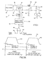
- electric arc welder 10 is shown in block diagram form.
- a three-phase rectifier 12 provides power to high speed switching-type power supply 14 across a DC link in the form of input leads 16, 18.
- high speed switching-type power supply 14 is an inverter, such as a Power Wave welding power supply available from Lincoln Electric Company of Cleveland, Ohio.
- a high speed switching chopper or other high speed switching-type power supply can also be employed.
- High speed switching-type power supply 14 performs a preselected welding process.
- high speed switching-type power supply 14 preferably switches at about 18 kHz or higher, and more preferably at 40 kHz or higher.
- High speed switching-type power supply 14 energizes welding circuit 20 that includes inductor 22 and electrode 24 forming an arc gap with workpiece 26 during performance of the welding operation.
- electrode 24 is a forward advancing welding wire from a supply spool. The welding wire is driven toward workpiece 26 at a selected wire speed during performance of the welding operation.
- Controller 30 controls high speed switching-type power supply 14 during the welding operation.
- controller 30 is a digital device including waveform generator 32 that outputs power level waveform 34 represented by a line that is the input to pulse width modulator 36.
- Pulse width modulator 36 produces pulse train 38 (represented by a line) of pulses with pulse widths corresponding to the power level of waveform 34.
- waveform 34 is converted into pulse width modulated pulse train signal 38 by pulse width modulator 36.
- Pulse width modulator 36 produces pulses of controlled width at a frequency preferably above 18 kHz, and more preferably about 40 kHz or higher, which is the input to high speed switching-type power supply 14.
- the power supply switching is controlled by pulse-width modulated pulse train 38 to energize welding circuit 20 in accordance with power level waveform 34.
- Waveform 34 implements a desired welding process.
- a welding process is made up of a waveform train of repeating waveforms.
- power level waveform 34 has a preselected wave shape for generating a welding process pulse.
- P avg is the average power
- v(t) is the instantaneous voltage
- i(t) is the instantaneous welding current
- v(t)i(t) is the instantaneous power
- T 1 and T 2 are the starting and ending time points of the time interval, respectively, of the integration.
- the time interval [T 1 , T 2 ] preferably corresponds to one pulse or a plurality of pulses.
- the pulse time interval may vary for successive pulses.
- the starting and stopping times T 1 and T 2 are extracted from waveform 34 as event signals T determined from a characteristic feature of waveform 34.
- V avg ⁇ T 1 T 2 ⁇ v t d t T 2 - T 1
- I avg ⁇ T 1 T 2 ⁇ i t d t T 2 - T 1
- the waveform includes a stepped pulse that is 500 amperes for 25% of the time and 100 amperes for 75% of the time
- the rms value is 265 amperes, while the average value is 200 amperes. In this case, the rms values provide a more accurate true heat value.
- controller 30 of electric arc welder 10 implements an exemplary pulse welding process in which the magnitude of waveform 34 is controlled using an rms current 40 that is calculated from an instantaneous welding current I a 42 measured across shunt 44.
- rms current 40 is compared with set rms current 46 by digital error amplifier 48 to produce error signal 50 that controls an amplitude of waveform 34 to maintain a constant rms current.
- control is suitably based on an rms voltage calculated from instantaneous welding voltage V a 52 measured across the weld by voltmeter 54.
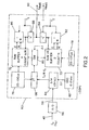
- computation of the rms current from instantaneous welding current I a 42 includes processing with analog-to-digital converter 56 to produce digitized instantaneous current 58, which is the input to digital signal processing block 60.
- Digital signal processing block 60 performs the current squared integration of Equation (3) digitally as a Riemann sum, dividing the current into time intervals ⁇ t defined by oscillator 62 for the summing.
- the digitizing interval ⁇ t for the Riemann sum is suitably about 0.1 milliseconds to provide adequate samples for each pulse or repetition of waveform 34.
- Sample-and-hold circuit 64 holds the digitized current for the period ⁇ t, and squaring processor 66 computes the square of the held current value.
- the summing preferably employs two alternating storage buffers, namely first buffer 70 (identified as Buffer A), and second buffer 72 (identified as Buffer B). Values are stored in the active buffer at intervals 76, 78 that are preferably in a range of about 0.025-0.100 milliseconds.
- switch 80 transfers values at time intervals ⁇ t to first buffer 70, which accumulates the current-squared values and also maintains a sample count N of a number of accumulated current samples.
- the contents of second buffer 72 are processed by division processor 82 to divide by the number of samples N, and by square-root processor 84 to complete computation of the root-mean-square calculation of Equation (3).
- Second accumulator 72 is cleared, and switch 80 subsequently transfers current-squared samples into second accumulator 72.
- division processor 86 the contents of first buffer 70 are processed by division processor 86 to divide by the number of samples N, and by square-root processor 88 to complete computation of the root-mean-square calculation of Equation (3).
- FIGURE 7 shows a simplified block diagram of digital signal processing block 60, which omits the details of the alternating summation buffers 70, 72 and related switching circuitry that are shown in detail in FIGURE 2 .
- current-squaring block 66, switch 80, and alternating summation blocks 70, 72 are represented by a single summation block 100 that sums current-squared samples between occurrences of the event signal T triggered by a characteristic of waveform 34, and also maintains the count N of the number of accumulated samples.
- Division background processes 82, 86 of FIGURE 2 are represented by a single normalization background process 102 in FIGURE 7 .
- Square-root background processes 84, 88 of FIGURE 2 are represented by a single square root background process 104 in FIGURE 7 .
- FIGURE 8 shows rms voltage digital signal processing block 60' in a simplified form analogous to the simplified form of FIGURE 7.
- the digitized voltage is processed by sample-and-hold circuit 64' which holds the digitized voltage for the period ⁇ t.
- Voltage-squared summation block 100' sums voltage-squared samples and maintains a count N of the number of accumulated voltage samples.
- summation block 100' uses alternating summation buffers analogous to buffers 70, 72 shown for the current-squared summation in FIGURE 2 .
- Normalization background process 102' divides the voltage-squared sample sum by the number of samples N.
- Square root background process 104' takes the square root to complete implementation of the rms voltage V rms mathematically shown in Equation (3).
- FIGURE 9 shows average power digital signal processing block 60" in a simplified form analogous to the simplified form of FIGURE 7 .
- Sample-and-hold circuits 64, 64' which hold the digitized current and voltage, respectively, for the period ⁇ t, are accessed by current-times-voltage summation block 100" which sums current-times-voltage samples and maintains a count N of the number of accumulated current-times-voltage samples.
- summation block 100 uses alternating summation buffers analogous to buffers 70, 72 shown for the current-squared summation in FIGURE 2 .
- Normalization background process 102 divides the current-times-voltage sample sum by the number of samples N to produce the average power P avg shown mathematically in Equation (1).
- Digital signal processing blocks 60, 60', 60" compute the rms current, the rms voltage, and the average power as Riemann sums.
- FIGURE 4 shows exemplary current waveform 120 that is digitally sampled. Each digital sample is represented by a rectangular sample bar 122 of time duration ⁇ t and height corresponding to the digitized value of current waveform 120 held by sample-and-hold circuit 64 at the time interval ⁇ t.
- Digital signal processing blocks 60, 60', 60" are optionally implemented as separate processing pathways that execute in parallel. However, in a preferred embodiment digital signal processing blocks 60, 60', 60" use some common digital signal processing blocks into which the sampled voltage and current signals are time-domain multiplexed. Such a multiplexing approach reduces the amount of circuitry required.
- Each summation (voltage-squared, current-squared, and voltage-times-current) has its own alternating summation buffer set (for example, summation buffer set 70, 72 for summing current-squared values as shown in FIGURE 2 ).
- the process cycling employs four cycles 130, 132, 134, 136 each occupying one-fourth of the sampling period ⁇ t.
- ⁇ t For the exemplary ⁇ t equal 0.1 millisecond, each of the four cycles 130, 132, 134, 136 occupies 0.025 milliseconds.
- first cycle 130 the voltage V a and current I a are digitized and sample/held.
- second cycle 132 the current-squared is computed and added to the current-squared summation.
- third cycle 134 the voltage-squared is computed and added to the voltage-squared summation.
- fourth cycle 136 a check is performed to determine whether an event signal T has been detected, and the sample count is incremented. Moreover, throughout the cycling other processing, such as computation of the square roots of values stored in the inactive summation buffers, can be performed as background processes. Similarly, digital signal processing welding control operations, such as waveform shaping described by Blankenship 5,278,390, can be performed as background control processes during the cycling.
- FIGURE 3A illustrates current waveform 34 extending between first event signal T 1 and second event signal T 2 .
- Event signals T 1 , T 2 are are suitably generated by a circuit controlled by waveform 34.
- the circuit generates event signal T 1 responsive to onset of the rising edge of current pulse 140, and the circuit generates event signal T 2 responsive to onset of the rising edge of current pulse 142.
- the event signals can instead be generated by detecting another characteristic of the pulse, such as the falling edge of the current pulse.
- buffers 70, 72 are switched so that buffer 72 is used to accumulate current-squared samples of next pulse 142 of waveform 34, while buffer 70 in which the current-squared samples of pulse 140 are accumulated is shifted 152 into the background.
- the current-squared sum is divided 154 by the number of samples N and the square-root is taken 156 to complete the rms algorithm.
- the computed rms current value for pulse 140 is written 158 to a register for use in welding process control.
- a field programmable gate array includes cycle counter state machine 170 that updates two-bit counter 172. State machine 170 is configured to increment two-bit counter 172 each time the state changes. Each change of state corresponds to an occurrence of event signal T.
- DSP digital signal processing
- two-bit comparator 174 compares the value of two-bit counter 172 with previous counter value register 176 during fourth cycle 136 of FIGURE 2A .
- a change in the value of two-bit counter 172 indicated by the comparison corresponds to an occurrence of event signal T.
- digital gate 178 loads the new value of two-bit counter 172 into previous counter value register 176. In this arrangement, the value stored in two-bit counter 172 is not significant; rather, a change in the counter value is detected.
- the polarity of waveform 34 along with an auxiliary "Misc2" signal are input to state machine 170 through"OR" gate 174.
- This arrangement enables the FPGA to generate event signals T for pulse welding and for a.c. welding.
- Misc2 is set to zero so that the polarity signal feeds through to cycle counter state machine 170.
- Misc2 is set to one when the arc is shorted, and zero when the arc is not shorted.
- FIGURE 5A shows a graph of pulse current 180 and the value of Misc2 182 when pulse welding is used instead of A.C. welding.
- the digital signal processing performs a check 190 to see if an occurrence of event signal T has been detected. This is done by comparing the current value of two-bit counter 172 with stored counter value 176 using two-bit comparator 174. If no change in counter value has occurred, the digital signal processing continues to loop through the four states 130, 132, 134, 136 of FIGURE 2A . However, if check 190 detects an occurrence of event signal T, the rms value is computed 192 as set forth in Equation (3) and in accordance with FIGURES 2 and 7 .
- Computation 192 is a background digital signal process. Additionally, a buffer switch 194 is performed so that whichever buffer (buffer A 70 or buffer B 72) had been active is switched to the background, and whichever buffer (buffer B 72 or buffer A 70) had been the background buffer is made the active accumulation buffer.
- Exemplary digital signal processing circuitry and associated FPGA circuitry for substantially real-time computation of rms voltage V rms , rms current I rms , and average power P avg have been described with reference to FIGURES 1-9 .
- the described digital signal processing circuitry implements Equations (1) and (3) using Riemann sums, and is exemplary only. Those skilled in the art can readily modify the illustrated digital circuitry or substitute other digital circuitry to perform these computations or substantial equivalents thereof.
- the illustrated circuitry provides certain features that may be optionally omitted or modified.
- separate and independent digital signal processing pathways can be provided for computing each of the rms voltage V rms , rms current I rms , and average power P avg values.
- time-domain multiplexing aspects of the circuitry can be omitted.
- a single accumulator can be employed in conjunction with a storage register that stores the previous sum for background normalization/square root processing.
- the temporary storage may be omitted entirely, and the normalization/square root processing performed substantially in real time for intervals between successive event signals T.
- a trapezoidal or otherwise-shaped integral element can be substituted for rectangular sample bars 122 of the Riemann sum illustrated in FIGURE 4 .
- Those skilled in the art can make other modifications to the exemplary digital signal processing and FPGA circuitry illustrated herein for implementing Equations (1) and (3) as digital circuitry.
- digital signal processing block 200 computes the power factor (PF) in accordance with Equation (4) from the rms voltage V rms , rms current I rms , and average power P avg values.
- the denominator of Equation (4) is computed using multiplier 202 acting on the rms current I rms and rms voltage V rms output by digital signal processing blocks 60, 60' of FIGURES 7 and 8 , respectively.
- the average power P avg output by digital signal processing bloc 60" of FIGURE 9 is divided by this denominator using division block 204 to compute the power factor PF.
- Controller 30' is a modified version of controller 30 of FIGURE 1 .
- Digital error amplifier 48' produces error signal 50' based on the power factor PF.
- Digital error amplifier 48' compares the power factor PF output by digital signal processing block 200 (shown in detail in FIGURE 10 ) with PF set value 46'.
- Waveform generator 32' modifies selected waveform shape 210 based on error signal 50' as described in Blankenship 5,278,390 which is incorporated by reference herein.
- electric arc welder 10 of FIGURE 1 is similarly readily adapted to implement a constant current welding process in which heat input to the weld is controlled by adjusting the power factor PF.
- Controller 30" is a modified version of controller 30 of FIGURE 1 .
- the rms current 40 is compared with set rms current 46 by digital error amplifier 48 to produce current error signal 50 as in FIGURE 1 .
- a second digital error amplifier 220 produces power factor error signal 222 by comparing the power factor PF output by digital signal processing block 200 (shown in detail in FIGURE 10 ) with adjustable welding heat set value 224.
- Waveform generator 32" modifies selected waveform shape 210 based on error signals 50, 222 as described in Blankenship 5,278,390.
- digital error amplifier 48' the power factor error signal optionally incorporates digital filtering.
- digital error amplifier 48' includes difference operator 232 that computes difference signal 234 which is proportional to a difference between the computed power factor and power factor set value 46'. Difference value 234 is input into digital filter 236 which generates control signal 50' for adjusting the waveform shape in accordance with the method described in Blankenship 5,278,390.
- digital filter 236 is an infinite impulse response filter. The digital filter can be used to amplify the signal, smooth the signal, remove high frequency signal components, or otherwise adjust the control signal.
- V set is a set voltage value
- V avg is an average voltage value computed in accordance with Equation (5)
- a is an average voltage weighting factor implemented by multiplier 250
- V rms is the rms voltage of Equation (3) that is output by digital signal processing block 60' of FIGURE 8
- b is an rms voltage weighting factor implemented by multiplier 252.
- difference signal E(n) 246 is processed by digital filter 254, such as an infinite impulse response filter, to amplify, smooth, or otherwise manipulate difference signal E(n) 246 to produce control signal 256 for adjusting the waveform shape in accordance with the method described in Blankenship 5,278,390.
- digital filter 254 such as an infinite impulse response filter
- I set is a set current value
- I avg is an average current value computed in accordance with Equation (5)
- a is an average current weighting factor implemented by multiplier 270
- I rms is the rms current of Equation (3) that is output by digital signal processing block 60 of FIGURE 7
- b is an rms current weighting factor implemented by multiplier 272.
- difference signal E(n) 266 is processed by digital filter 274, such as an infinite impulse response filter, to amplify, smooth, or otherwise manipulate difference signal E(n) 266 to produce control signal 276 for adjusting the waveform shape in accordance with the method described in Blankenship 5,278,390.
- digital filter 274 such as an infinite impulse response filter
- waveform shape adjustment in accordance with the waveform shape adjustment method of Blankenship 5,278,390 is illustrated.
- Two waveforms 280, 282 are shown in solid and dashed lines, respectively.
- waveforms 280, 282 have equal rms values.
- the average value is generally different for waveforms 280, 282.
- waveform 282 has a reduced voltage or current background magnitude and an increased voltage or current magnitude in the pulse.
- pulse repetition period of waveforms 280, 282 may be different. This difference in repetition period is accounted for in the digital signal processing by performing the Riemann sums of Equations (1), (3), and (5) over intervals between successive event signals T, instead of performing the Riemann summing over time intervals of fixed length. Generating event signals T at a rising pulse edge or other identifiable characteristic of the waveform allows the summation interval to track the repetition period of the waveform as the repetition period is adjusted by the waveform shaping.
- two digital error amplifiers 300, 302 compute current and voltage error signals for use in a constant current, constant voltage welding process control.
- Digital error amplifier 300 includes difference operator 310, weighting factors a 312 and b 314, and digital filter 316.
- Digital error amplifier 300 has the same voltage inputs and general circuit topology as amplifier 240 of FIGURE 14 ; however, digital error amplifier 300 produces control signal 318 for controlling wire feed speed during the welding process. With increasing output of amplifier 300 the wire feed speed should be decreased, while with decreasing output of amplifier 300 the wire feed speed should be increased.
- Digital amplifier 302 includes difference operator 330, weighting factors c 332 and d 334, and digital filter 336.
- Digital error amplifier 302 has the same current inputs and general circuit topology as amplifier 260 of FIGURE 15 , and produces control output 338 for adjusting the waveform shape in accordance with the method described in Blankenship 5,278,390. Hence, the waveform shape and the wire feed speed are simultaneously controlled using digital error amplifiers 300, 302 to keep both voltage and current constant.
Landscapes
- Engineering & Computer Science (AREA)
- Physics & Mathematics (AREA)
- Plasma & Fusion (AREA)
- Mechanical Engineering (AREA)
- Theoretical Computer Science (AREA)
- Arc Welding Control (AREA)
- Generation Of Surge Voltage And Current (AREA)
Applications Claiming Priority (3)
| Application Number | Priority Date | Filing Date | Title |
|---|---|---|---|
| US42107802P | 2002-10-25 | 2002-10-25 | |
| US10/603,322 US7091445B2 (en) | 2002-10-25 | 2003-06-26 | Electric arc welder and method for controlling the welding process of the welder |
| EP03024610.2A EP1413381B1 (de) | 2002-10-25 | 2003-10-25 | Elektrische Lichtbogenschweissmaschine und Verfahren zur Steuerung des Schweissprozesses der Schweissmaschine |
Related Parent Applications (3)
| Application Number | Title | Priority Date | Filing Date |
|---|---|---|---|
| EP03024610.2 Division | 2003-10-25 | ||
| EP03024610.2A Division-Into EP1413381B1 (de) | 2002-10-25 | 2003-10-25 | Elektrische Lichtbogenschweissmaschine und Verfahren zur Steuerung des Schweissprozesses der Schweissmaschine |
| EP03024610.2A Division EP1413381B1 (de) | 2002-10-25 | 2003-10-25 | Elektrische Lichtbogenschweissmaschine und Verfahren zur Steuerung des Schweissprozesses der Schweissmaschine |
Publications (2)
| Publication Number | Publication Date |
|---|---|
| EP2626162A2 true EP2626162A2 (de) | 2013-08-14 |
| EP2626162A3 EP2626162A3 (de) | 2015-04-22 |
Family
ID=32073532
Family Applications (4)
| Application Number | Title | Priority Date | Filing Date |
|---|---|---|---|
| EP20130001079 Withdrawn EP2626162A3 (de) | 2002-10-25 | 2003-10-25 | Lichtbogenschweißgerät und -verfahren zur Steuerung des Schweißprozesses des Schweißgeräts |
| EP20130001081 Withdrawn EP2626164A3 (de) | 2002-10-25 | 2003-10-25 | Lichtbogenschweißgerät und -verfahren zur Steuerung des Schweißprozesses des Schweißgeräts |
| EP20130001080 Withdrawn EP2626163A3 (de) | 2002-10-25 | 2003-10-25 | Lichtbogenschweißgerät und -verfahren zur Steuerung des Schweißprozesses des Schweißgeräts |
| EP03024610.2A Expired - Lifetime EP1413381B1 (de) | 2002-10-25 | 2003-10-25 | Elektrische Lichtbogenschweissmaschine und Verfahren zur Steuerung des Schweissprozesses der Schweissmaschine |
Family Applications After (3)
| Application Number | Title | Priority Date | Filing Date |
|---|---|---|---|
| EP20130001081 Withdrawn EP2626164A3 (de) | 2002-10-25 | 2003-10-25 | Lichtbogenschweißgerät und -verfahren zur Steuerung des Schweißprozesses des Schweißgeräts |
| EP20130001080 Withdrawn EP2626163A3 (de) | 2002-10-25 | 2003-10-25 | Lichtbogenschweißgerät und -verfahren zur Steuerung des Schweißprozesses des Schweißgeräts |
| EP03024610.2A Expired - Lifetime EP1413381B1 (de) | 2002-10-25 | 2003-10-25 | Elektrische Lichtbogenschweissmaschine und Verfahren zur Steuerung des Schweissprozesses der Schweissmaschine |
Country Status (7)
| Country | Link |
|---|---|
| US (2) | US7091445B2 (de) |
| EP (4) | EP2626162A3 (de) |
| JP (1) | JP4418892B2 (de) |
| AU (1) | AU2003254709B2 (de) |
| BR (1) | BR0304585A (de) |
| CA (1) | CA2443884C (de) |
| MX (1) | MXPA03009742A (de) |
Families Citing this family (51)
| Publication number | Priority date | Publication date | Assignee | Title |
|---|---|---|---|---|
| US7091445B2 (en) * | 2002-10-25 | 2006-08-15 | Lincoln Global, Inc. | Electric arc welder and method for controlling the welding process of the welder |
| US6930279B2 (en) * | 2003-07-25 | 2005-08-16 | Lincoln Global, Inc. | Electric arc welder and method for controlling the welding process of the welder |
| EP1512481A3 (de) * | 2003-09-02 | 2011-09-28 | Illinois Tool Works Inc. | Spannungsgeregeltes GMA-Schweissen mit einer Konstantstromleistungsquelle und einem Drahtvorschubgerät mit variabler Verstärkung |
| JP4490088B2 (ja) * | 2003-09-12 | 2010-06-23 | 株式会社ダイヘン | パルスアーク溶接の出力制御方法及びアーク長揺動パルスアーク溶接の出力制御方法 |
| US7138601B2 (en) * | 2004-01-22 | 2006-11-21 | Illinois Tool Works Inc. | Method and apparatus for arc welding with arc control |
| US8269141B2 (en) * | 2004-07-13 | 2012-09-18 | Lincoln Global, Inc. | Power source for electric arc welding |
| AT502327B1 (de) * | 2005-08-30 | 2009-07-15 | Fronius Inernat Gmbh | Verfahren zum steuern eines schutzvisiers |
| US9687931B2 (en) | 2006-12-05 | 2017-06-27 | Lincoln Global, Inc. | System for measuring energy using digitally controlled welding power sources |
| US7724805B1 (en) * | 2006-09-06 | 2010-05-25 | Rf Micro Devices, Inc. | Fast RMS measurement of input I/Q signals in a W-CDMA system |
| US8963045B2 (en) * | 2006-09-19 | 2015-02-24 | Lincoln Global, Inc. | Non-linear adaptive control system and method for welding |
| US9895760B2 (en) | 2007-09-26 | 2018-02-20 | Lincoln Global, Inc. | Method and system to increase heat input to a weld during a short-circuit arc welding process |
| JP4932672B2 (ja) * | 2007-10-26 | 2012-05-16 | 株式会社 シンワ | 形状記憶合金部材の加熱装置 |
| US8260976B1 (en) * | 2009-01-30 | 2012-09-04 | American Megatrends, Inc. | Multiple frequency state detection for serial I/O interfaces |
| JP5083415B2 (ja) * | 2009-04-08 | 2012-11-28 | パナソニック株式会社 | アーク溶接方法およびアーク溶接装置 |
| US8455794B2 (en) * | 2009-06-03 | 2013-06-04 | Illinois Tool Works Inc. | Welding power supply with digital control of duty cycle |
| US8604384B2 (en) | 2009-06-18 | 2013-12-10 | Illinois Tool Works Inc. | System and methods for efficient provision of arc welding power source |
| ITVI20090247A1 (it) * | 2009-10-07 | 2011-04-08 | Ter Srl | Procedimento e sistema per il controllo della corrente d'arco erogata nei processi di saldatura |
| US10766089B2 (en) | 2010-07-14 | 2020-09-08 | Illinois Tool Works | Heat input control for welding systems |
| US8618441B2 (en) | 2010-10-05 | 2013-12-31 | Lincoln Global, Inc. | Output control for auto-reconnect welding/cutting equipment |
| CA2837385A1 (en) | 2011-05-26 | 2012-11-29 | Thermal Dynamics Corporation | Improved initiation of welding arc by restricting output |
| CN103747912B (zh) * | 2011-05-26 | 2016-08-17 | 维克托设备公司 | 产生焊接的系统及利用基于计算的焊接输出功率的电压和送丝速度的修正控制焊机的方法 |
| US9511444B2 (en) * | 2011-07-15 | 2016-12-06 | Illinois Tool Works Inc. | Digital communication based arc control welding system and method |
| JP2013146735A (ja) * | 2012-01-17 | 2013-08-01 | Daihen Corp | 溶接電源の保護制御方法 |
| JP2013151012A (ja) * | 2012-01-26 | 2013-08-08 | Daihen Corp | 溶接電源の保護制御方法 |
| CN104322142B (zh) * | 2012-05-18 | 2016-05-04 | 高周波热錬株式会社 | 感应加热系统、感应加热方法、输出监测装置、输出监测方法和感应加热装置 |
| US9662735B2 (en) | 2012-06-08 | 2017-05-30 | Illinois Tool Works Inc. | Welding wire feeder power application system and method |
| US9463523B2 (en) | 2012-06-08 | 2016-10-11 | Illinois Tool Works Inc. | Controlled waveform welding wire feeder system and method |
| US10406621B2 (en) | 2012-06-08 | 2019-09-10 | Illinois Tool Works Inc. | Polarity sensing welding wire feeder system and method |
| US9878393B2 (en) | 2012-06-08 | 2018-01-30 | Illinois Tool Works Inc. | Welding wire feeder power control system and method |
| US10105781B2 (en) | 2012-06-08 | 2018-10-23 | Illinois Tool Works Inc. | Welding system inrush current control system and method |
| US10384289B2 (en) | 2012-06-08 | 2019-08-20 | Illinois Tool Works Inc. | Welding wire feeder bus control system and method |
| CN102848051B (zh) * | 2012-09-13 | 2015-04-01 | 刘裕国 | 一种起弧脉冲峰值电流控制电焊机及其控制方法 |
| US10315268B2 (en) | 2012-11-07 | 2019-06-11 | Lincoln Global, Inc. | Method and system to control heat input in a welding operation |
| US9333582B2 (en) * | 2012-11-07 | 2016-05-10 | Lincoln Global, Inc. | Method and system to control heat input in a welding operation |
| US11185940B2 (en) | 2014-03-12 | 2021-11-30 | Illinois Tool Works Inc. | Systems and methods for controlling an output power of a welding power supply |
| US11491573B2 (en) | 2015-08-17 | 2022-11-08 | Illinois Tool Works Inc. | Portable advanced process module |
| US10179369B2 (en) | 2015-10-27 | 2019-01-15 | Lincoln Global, Inc. | Welding system for AC welding with reduced spatter |
| US10734918B2 (en) | 2015-12-28 | 2020-08-04 | Illinois Tool Works Inc. | Systems and methods for efficient provision of arc welding power source |
| US10722967B2 (en) | 2017-01-27 | 2020-07-28 | Lincoln Global, Inc. | Apparatus and method for welding with AC waveform |
| US10682719B2 (en) | 2017-01-27 | 2020-06-16 | Lincoln Global, Inc. | Apparatus and method for welding with AC waveform |
| US10744584B2 (en) | 2017-01-27 | 2020-08-18 | Lincoln Global, Inc. | Apparatus and method for welding with AC waveform |
| US11110536B2 (en) | 2017-01-27 | 2021-09-07 | Lincoln Global, Inc. | Apparatus and method for welding with AC waveform |
| US11027355B2 (en) * | 2017-03-09 | 2021-06-08 | Illinois Tool Works | Welding power supplies, wire feeders, and systems to measure a weld circuit resistance via communications over the weld circuit |
| US11660695B2 (en) | 2017-03-09 | 2023-05-30 | Illinois Tool Works Inc. | Welding power supplies, wire feeders, and systems to measure a weld cable voltage drop |
| US10632557B2 (en) | 2017-03-16 | 2020-04-28 | Illinois Tool Works Inc. | Methods and apparatus to determine and display heat input to a weld |
| US10906115B2 (en) | 2017-11-16 | 2021-02-02 | Illinois Tool Works Inc. | Automatic process and/or set up of welding type system |
| JP7026576B2 (ja) * | 2018-05-28 | 2022-02-28 | 株式会社神戸製鋼所 | 溶接状態判定装置、溶接状態判定方法、及びプログラム |
| JP7645453B2 (ja) | 2020-06-17 | 2025-03-14 | パナソニックIpマネジメント株式会社 | 接続装置 |
| CN116266884A (zh) * | 2021-12-13 | 2023-06-20 | 无锡威卓智能机器人有限公司 | 一种脉冲弧焊的图像采集方法和系统 |
| CN115373360B (zh) * | 2022-10-20 | 2023-03-03 | 山东芯合机器人科技有限公司 | 一种基于工业机器人加工过程质量监控系统 |
| CN116275403B (zh) * | 2023-05-06 | 2025-09-02 | 唐山松下产业机器有限公司 | 脉冲弧长调整方法、装置及焊接系统 |
Citations (1)
| Publication number | Priority date | Publication date | Assignee | Title |
|---|---|---|---|---|
| US5278390A (en) | 1993-03-18 | 1994-01-11 | The Lincoln Electric Company | System and method for controlling a welding process for an arc welder |
Family Cites Families (29)
| Publication number | Priority date | Publication date | Assignee | Title |
|---|---|---|---|---|
| US2293079A (en) * | 1939-11-22 | 1942-08-18 | Ranke Hans | Electric welding apparatus and method |
| US2636102A (en) * | 1950-06-27 | 1953-04-21 | Union Carbide & Carbon Corp | Automatic metal arc welding system |
| US3236997A (en) * | 1963-05-24 | 1966-02-22 | Welding Research Inc | System for controlling length of welding arc |
| US4125759A (en) * | 1974-10-17 | 1978-11-14 | Osaka Transformer Co., Ltd. | Method and apparatus for shortcircuiting arc welding |
| KR840002189B1 (ko) * | 1980-07-08 | 1984-11-28 | 미쯔비시덴끼 가부시기가이샤 | 펄스 아아크 용접장치 |
| JPS5719175A (en) * | 1980-07-08 | 1982-02-01 | Mitsubishi Electric Corp | Consumable electrode type pulse arc welding machine |
| US4301355A (en) * | 1980-08-04 | 1981-11-17 | Dimetrics, Inc. | Gas metal arc welding system |
| CA1171917A (en) * | 1981-11-20 | 1984-07-31 | Ronald W. Charette | Consumable welding electrode feed control in response to arc voltage and electrode speed |
| US5149940A (en) * | 1983-02-24 | 1992-09-22 | Beckworth Davis International Inc. | Method for controlling and synchronizing a welding power supply |
| US4821202A (en) * | 1983-02-24 | 1989-04-11 | Beckworth Davis International, Inc. | Apparatus microprocessor controlled welding |
| US4721906A (en) | 1985-08-06 | 1988-01-26 | Duffers Scientific, Inc. | One step RMS system |
| ATE95741T1 (de) * | 1986-06-04 | 1993-10-15 | Welding Ind Of Australia | Impulslichtbogenschweissen. |
| US4897522A (en) * | 1989-02-06 | 1990-01-30 | The Lincoln Electric Company | Output control circuit for inverter |
| WO1991001842A1 (fr) * | 1989-08-02 | 1991-02-21 | Mitsubishi Denki Kabushiki Kaisha | Appareil de soudage par impulsions |
| TW214522B (en) * | 1992-05-18 | 1993-10-11 | Lincoln Electric Co | Control system for alternating current tig welder |
| JP3177715B2 (ja) * | 1992-05-29 | 2001-06-18 | 大阪電気株式会社 | 消耗電極式アーク電圧自動制御方法及び制御装置 |
| US5304776A (en) * | 1993-03-24 | 1994-04-19 | Steven R. Buerkel | System for welding pipes |
| US5386096A (en) * | 1993-12-23 | 1995-01-31 | Square D Company | Progressive current limit control for a resistance welder |
| US5513093A (en) * | 1994-03-11 | 1996-04-30 | Miller Electric Mfg. Co. | Reduced open circuit voltage power supply and method of producing therefor |
| JP3162639B2 (ja) * | 1996-11-22 | 2001-05-08 | 株式会社三社電機製作所 | 電源装置 |
| US5991169A (en) * | 1998-03-16 | 1999-11-23 | Lincoln Global, Inc. | Arc welding power supply |
| US6115273A (en) * | 1998-07-09 | 2000-09-05 | Illinois Tool Works Inc. | Power converter with low loss switching |
| TW445192B (en) * | 1999-04-12 | 2001-07-11 | Tri Tool Inc | Control method and apparatus for an arc welding system |
| US6236017B1 (en) * | 1999-07-01 | 2001-05-22 | Bechtel Bwxt Idaho, Llc | Method and apparatus for assessing weld quality |
| US6291798B1 (en) | 1999-09-27 | 2001-09-18 | Lincoln Global, Inc. | Electric ARC welder with a plurality of power supplies |
| JP2001259837A (ja) | 2000-03-22 | 2001-09-25 | Hitachi Ltd | 高周波パルス溶接方法及び装置 |
| US6365874B1 (en) * | 2000-05-22 | 2002-04-02 | Lincoln Global, Inc. | Power supply for electric arc welding |
| US6441342B1 (en) * | 2000-11-20 | 2002-08-27 | Lincoln Global, Inc. | Monitor for electric arc welder |
| US7091445B2 (en) * | 2002-10-25 | 2006-08-15 | Lincoln Global, Inc. | Electric arc welder and method for controlling the welding process of the welder |
-
2003
- 2003-06-26 US US10/603,322 patent/US7091445B2/en not_active Expired - Lifetime
- 2003-10-02 CA CA002443884A patent/CA2443884C/en not_active Expired - Fee Related
- 2003-10-14 AU AU2003254709A patent/AU2003254709B2/en not_active Ceased
- 2003-10-24 MX MXPA03009742A patent/MXPA03009742A/es active IP Right Grant
- 2003-10-24 JP JP2003363998A patent/JP4418892B2/ja not_active Expired - Fee Related
- 2003-10-24 BR BR0304585-4A patent/BR0304585A/pt not_active Application Discontinuation
- 2003-10-25 EP EP20130001079 patent/EP2626162A3/de not_active Withdrawn
- 2003-10-25 EP EP20130001081 patent/EP2626164A3/de not_active Withdrawn
- 2003-10-25 EP EP20130001080 patent/EP2626163A3/de not_active Withdrawn
- 2003-10-25 EP EP03024610.2A patent/EP1413381B1/de not_active Expired - Lifetime
-
2006
- 2006-07-10 US US11/483,899 patent/US7573002B2/en not_active Expired - Lifetime
Patent Citations (1)
| Publication number | Priority date | Publication date | Assignee | Title |
|---|---|---|---|---|
| US5278390A (en) | 1993-03-18 | 1994-01-11 | The Lincoln Electric Company | System and method for controlling a welding process for an arc welder |
Non-Patent Citations (1)
| Title |
|---|
| JACK W. CRINSHAW: "Embedded Systems Programming", INTEGER SQUARE ROOT, February 1998 (1998-02-01) |
Also Published As
| Publication number | Publication date |
|---|---|
| AU2003254709A1 (en) | 2004-05-13 |
| EP1413381B1 (de) | 2019-01-09 |
| EP1413381A3 (de) | 2009-02-25 |
| US20060249497A1 (en) | 2006-11-09 |
| EP2626162A3 (de) | 2015-04-22 |
| EP2626163A3 (de) | 2015-04-22 |
| JP2004141967A (ja) | 2004-05-20 |
| MXPA03009742A (es) | 2005-04-19 |
| EP2626164A3 (de) | 2015-04-22 |
| CA2443884A1 (en) | 2004-04-25 |
| US7573002B2 (en) | 2009-08-11 |
| EP1413381A2 (de) | 2004-04-28 |
| US7091445B2 (en) | 2006-08-15 |
| EP2626163A2 (de) | 2013-08-14 |
| BR0304585A (pt) | 2004-08-31 |
| CA2443884C (en) | 2007-12-11 |
| JP4418892B2 (ja) | 2010-02-24 |
| US20040079740A1 (en) | 2004-04-29 |
| EP2626164A2 (de) | 2013-08-14 |
| AU2003254709B2 (en) | 2005-02-24 |
Similar Documents
| Publication | Publication Date | Title |
|---|---|---|
| EP1413381B1 (de) | Elektrische Lichtbogenschweissmaschine und Verfahren zur Steuerung des Schweissprozesses der Schweissmaschine | |
| US6930279B2 (en) | Electric arc welder and method for controlling the welding process of the welder | |
| US7064290B2 (en) | Electric arc welder and method for controlling the welding process of the welder | |
| RU2223849C2 (ru) | Способ управления процессами электродуговой сварки и сварочный аппарат для осуществления этого способа | |
| KR970006324B1 (ko) | 저항 스폿용접기용 전원제어장치 및 선간 전압 감시장치/보정장치 | |
| HK1075429A (en) | Electric arc welder and method for controlling the welding process of the welder | |
| KR100520740B1 (ko) | 전기 아크 용접기와 그 용접기의 용접 공정의 제어 방법 | |
| JP2645145B2 (ja) | 表面あらさ測定装置 | |
| EP0570901A2 (de) | Steuerungsanordnung für mit Wechselstrom betriebene Wolfram-Inertgas-Schweissgeräte | |
| JPH0335931A (ja) | 放電解析装置 | |
| JPH0347679A (ja) | アーク溶接装置 |
Legal Events
| Date | Code | Title | Description |
|---|---|---|---|
| PUAI | Public reference made under article 153(3) epc to a published international application that has entered the european phase |
Free format text: ORIGINAL CODE: 0009012 |
|
| AC | Divisional application: reference to earlier application |
Ref document number: 1413381 Country of ref document: EP Kind code of ref document: P |
|
| AK | Designated contracting states |
Kind code of ref document: A2 Designated state(s): AT BE BG CH CY CZ DE DK EE ES FI FR GB GR HU IE IT LI LU MC NL PT RO SE SI SK TR |
|
| PUAL | Search report despatched |
Free format text: ORIGINAL CODE: 0009013 |
|
| AK | Designated contracting states |
Kind code of ref document: A3 Designated state(s): AT BE BG CH CY CZ DE DK EE ES FI FR GB GR HU IE IT LI LU MC NL PT RO SE SI SK TR |
|
| RIC1 | Information provided on ipc code assigned before grant |
Ipc: B23K 9/09 20060101AFI20150318BHEP Ipc: B23K 9/095 20060101ALI20150318BHEP Ipc: B23K 9/10 20060101ALI20150318BHEP |
|
| STAA | Information on the status of an ep patent application or granted ep patent |
Free format text: STATUS: THE APPLICATION IS DEEMED TO BE WITHDRAWN |
|
| 18D | Application deemed to be withdrawn |
Effective date: 20151023 |