EP2625988A1 - Removable fastener and associated telescopic control rod - Google Patents
Removable fastener and associated telescopic control rod Download PDFInfo
- Publication number
- EP2625988A1 EP2625988A1 EP12155127.9A EP12155127A EP2625988A1 EP 2625988 A1 EP2625988 A1 EP 2625988A1 EP 12155127 A EP12155127 A EP 12155127A EP 2625988 A1 EP2625988 A1 EP 2625988A1
- Authority
- EP
- European Patent Office
- Prior art keywords
- rod
- fastening
- telescopic rod
- connecting means
- frame
- Prior art date
- Legal status (The legal status is an assumption and is not a legal conclusion. Google has not performed a legal analysis and makes no representation as to the accuracy of the status listed.)
- Withdrawn
Links
Images


Classifications
-
- A—HUMAN NECESSITIES
- A47—FURNITURE; DOMESTIC ARTICLES OR APPLIANCES; COFFEE MILLS; SPICE MILLS; SUCTION CLEANERS IN GENERAL
- A47H—FURNISHINGS FOR WINDOWS OR DOORS
- A47H1/00—Curtain suspension devices
- A47H1/10—Means for mounting curtain rods or rails
- A47H1/14—Brackets for supporting rods or rails
- A47H1/142—Brackets for supporting rods or rails for supporting rods
-
- A—HUMAN NECESSITIES
- A47—FURNITURE; DOMESTIC ARTICLES OR APPLIANCES; COFFEE MILLS; SPICE MILLS; SUCTION CLEANERS IN GENERAL
- A47H—FURNISHINGS FOR WINDOWS OR DOORS
- A47H1/00—Curtain suspension devices
- A47H1/02—Curtain rods
- A47H1/022—Curtain rods extensible
Definitions
- the invention relates to the field of fastening systems for rods including telescopic for hanging curtains, curtains or other elements on a door, window or other element having a rigid frame or frame.
- the rod is telescopic in that it comprises an inner rigid tube capable of sliding axially in an external rigid coaxial tube.
- the tubes overlap for part of their length, in the central part of the rod when stretched.
- the rod may further comprise a compression spring disposed inside the tubes or a screw spring system, at the central overlap of the tubes.
- the tip and the support are integral regardless of the embodiments of this invention.
- the brackets delimit the distance on which the curtain can be supported. But the tabs do not exceed the window frame in particular for reasons of balancing applied forces, the curtain will not exceed more. This is a disadvantage particularly aesthetic but also functional because a curtain (carried by such a rod) is primarily intended to hide an opening, including frame. This prior art does not allow it.
- the invention aims to overcome the disadvantages of the state of the art and in particular to provide a removable attachment for a telescopic rod which is simple to manufacture and assembly, and which largely masks the opening, including chassis.
- the frame may relate to a window, a door or an opening in a general way when it comes to hide or decorate such elements by a means such as a curtain, a curtain or other.
- the tip of the rod may comprise an at least partially cylindrical element for extending longitudinally said telescopic rod. This aspect advantageously allows to deploy the curtain supported by the rod thus fixed, a length comprising the opening and at least a portion of the frame of the opening in question.
- first and / or second holding member (s) consists of a ring having at least one longitudinal slot along part of its length.
- first and / or the second element (s) of retention may consist of a cylindrical compression tension spring.
- the fastening tab cooperates with the connecting means by a contact located between the first and the second holding member.
- An opening in the tab is advantageously provided for this purpose.
- the opening may be provided with a thread in which is screwed the connecting means.
- the invention further relates to a telescopic rod cooperating with at least two fastening systems and comprising two rigid tubes nestable one inside the other, said inner spring being a self-locking compression tension spring housed inside said tubes at the level their covering ends; this spring comprises zones of different stiffness.
- Rigid tubes can be made of stainless steel.
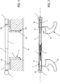
- the figure 1 relates to a first embodiment of the invention.
- the attachment thus illustrated is intended to equip a telescopic rod consisting of two coaxial tubes 1, 2 which can slide relative to one another and having a covering zone whose length varies according to the size of the window or frame on which is fixed the rod.
- the rod can be adapted to 4 door frame or window of varying dimensions.
- a spring 3 visible on the figure 2 is housed and in contact with the interior of the two tubes 1, 2 at their overlapping areas and it contributes to maintaining a given length of rod.
- a compression spring consisting of zones of different stiffness is chosen; he is better represented on the figure 7 .
- the fastening or fastening system comprises in particular a fastening tab 5 allowing on the one hand the grip on the chassis 4 and on the other hand the maintenance of the curtain at a given distance from a window (or equivalent) 10 maintained by the frame 4.
- the distance between the window (or equivalent) and the curtain may vary if an extension element is provided on the latching lug.
- a window is however not necessary because it is possible to place the binding according to the invention on a door frame with or without a door or on any other frame; it is in any case not only to maintain a curtain, net or equivalent on a frame but also to maintain it at a distance from the main plane of the frame 4.
- This lug 5 generally comprises three planar parts: a first part 51 intended to come into contact and rest with a first surface of the frame 4.
- the first part 51 is preferably provided with a lug 510 and a through orifice 515 in which is inserted by force a blocking pad for example rubber.
- the rubber pad protrudes from the side of the frame 4 by a thickness substantially equal to that of the pin 510 so that it makes a quasi-point contact of the pin 510 in the frame 4
- the first part 51 may be provided with an additional element, called an extension, intended to increase the distance between the frame 4 and the plane of attachment of the curtain or curtain (plane passing through the longitudinal axis of the rod). This is a possible arrangement within the scope of the invention.
- the tab 5 comprises a second portion 52 perpendicular to the first portion 51 and which is adapted to come into contact with a second surface of the frame 4, perpendicular to the first surface.
- the third portion 53 of the hooking tab 5 extends in a plane parallel to that of the first part and is shifted along the length of the rod towards one of its ends. This particular form of the tab 5 makes it possible to balance the forces exerted by the curtain on the frame 4. This form is however not mandatory and any form technically equivalent is to be considered.
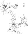
- the attachment comprises connecting means 6 with one end of the rod. More precisely, the connecting means 6 comprise a first elastic retaining element (or piece) 61 and a second elastic holding element 62. Each retaining element 61, 62 advantageously cooperates with its outer surface with the inner surface of the retaining element 61. one of the tubes 1, 2 forming the telescopic rod, more precisely with the free end of one of the tubes 1, 2. A radially elastic holding is thus created.
- the element 61, 62 is also in contact for elastic retention with the inner wall of a hollow tip 7 and intended to cap a free end of one of the tubes 1, 2 constituting the telescopic rod.
- the elastic holding element 6 advantageously provides a connection and an elastic radial retention of the rod vis-à-vis at least one endpiece 7.
- the first element 61 has a smaller outer diameter than the second holding element 62; each outer diameter is chosen slightly greater than the inside diameter of the endpiece 7 and / or the end of the telescopic tube on which a tip is intended to come to cap.
- By 'coming to cap' is meant to come to be positioned in the axial extension of one end of one of the tubes 1, 2, beyond the fixing lug 5.
- the holding element 6 is held in force by inside a tip 7 and / or an end of a tube 1, 2.
- outer diameters may be of the same value.
- the figure 3 represents another embodiment of the invention according to which the first 61 and the second 62 holding elements consist of two separate pieces, here two rings open.
- Each ring 61, 62 is advantageously mounted on a cylindrical piece 8 formed of two zones of different outside diameters 81, 82.
- the zones 81, 82 are separated by a collar 83.
- a retaining collar 84, 85 is further provided at each end of the piece 8 to retain axially, with the collar 83, each of the holding elements.
- the holding element 6 and cylindrical piece 8 is preferably force-fitted inside respectively of a nozzle 7 and one of the tubes 1, 2, in cooperation with the fastening lug 5.
- At least one of the end pieces 7 is positioned on the free and protruding end of an elastic element 61, 62.
- the end piece 7 here reliably caps the ends of the telescopic rod in place on the fasteners 5.
- the nozzle 7 may comprise a cylindrical element 9 intended to extend longitudinally the bead formed of the tubes 1, 2, distally beyond the fixing 5.
- the cylindrical element or extension 9 may be provided in one piece with the endpiece 7, or it may consist of an independent piece longitudinally interposed between the attachment 5 and the endpiece 7.
- the right part of the figure 2 as well as the left part of the figure 3 illustrate an extension 9 independent of the tip 7.
- the extension 9 is force-fitted on the first 61 or on the second retaining elastic element 62, which protrudes outwardly beyond the fastening element 5.
- the extender 9 is fitted inside the tip 7, preferably elastically.
- the extension 9 can support and position for example a tab of a curtain, which is a means of retaining the latter at one end of the rod. At this level the rod exceeds beyond the frame 4 of the window so that the curtain thus masks the frame 4 of the window (or other opening of this type). This is very popular with users.
- FIGS. 5 and 6 illustrate embodiments where the resilient retaining member 61, 62 is constituted by a compression tension spring fitted and fitted in the same manner as the rings described above in connection with other embodiments of the invention.
- An O-ring can, technically equivalent, replace the compression pull spring.
- the figure 5 shows an embodiment with extender 9 while the figure 6 illustrates an example where the tip 7 is the end portion of the rod.
- the figure 7 illustrates an embodiment in which the endpiece 7 and the holding means 6 are formed of a single piece 67, rivet type. All the features listed above are of course present.
- the part 67 is force-fitted inside one of the ends of a tube 1, 2 constituting the telescopic tube after passing through (for example by screwing or riveting) the opening 530 of the lug 5 disposed in the axial extension of the tube.
Abstract
Description
L'invention se rapporte au domaine des systèmes de fixation pour des tringles notamment télescopiques permettant d'accrocher des rideaux, voilages ou autres éléments sur une porte, une fenêtre ou autre élément ayant un cadre rigide ou châssis.The invention relates to the field of fastening systems for rods including telescopic for hanging curtains, curtains or other elements on a door, window or other element having a rigid frame or frame.
Il s'agit en effet de fixer de manière amovible c'est-à-dire réversible et non définitive, une tringle sur un tel châssis. La tringle est télescopique en ce sens qu'elle comprend un tube rigide interne susceptible de coulisser axialement dans un tube rigide coaxial externe. Les tubes se recouvrent sur une partie de leur longueur, en partie centrale de la tringle une fois étirée. La tringle peut comprendre en outre un ressort de compression disposé à l'intérieur des tubes ou encore un système de ressort à visser, au niveau du recouvrement central des tubes.It is indeed to fix detachably that is to say reversible and not definitive, a rod on such a frame. The rod is telescopic in that it comprises an inner rigid tube capable of sliding axially in an external rigid coaxial tube. The tubes overlap for part of their length, in the central part of the rod when stretched. The rod may further comprise a compression spring disposed inside the tubes or a screw spring system, at the central overlap of the tubes.
De nombreux systèmes de fixation de telles tringles sont connus et appréciés des utilisateurs car ils permettent de fixer les tringles sans clous ni vis ni autre système équivalent. Ils permettent en effet une fixation par un simple vissage ou étirement des deux tubes l'un par rapport à l'autre.Many fastening systems such rods are known and appreciated by users because they allow to fix the rods without nails or screws or other equivalent system. They allow in fact a fixation by simply screwing or stretching the two tubes relative to each other.
Dans le document
Ainsi l'embout et le support sont solidaires quelles que soient les formes de réalisation de cette invention. De plus les pattes de fixation délimitent la distance sur laquelle le rideau peut être supporté. Or les pattes ne dépassant nullement du châssis de la fenêtre notamment pour des raisons d'équilibrage des efforts appliqués, le rideau n'en dépassera pas davantage. Ceci constitue un inconvénient notamment d'ordre esthétique mais également d'ordre fonctionnel puisque un rideau ( porté par une telle tringle) est avant tout destiné à masquer une ouverture, cadre compris. Cet art antérieur ne le permet pas.Thus the tip and the support are integral regardless of the embodiments of this invention. In addition, the brackets delimit the distance on which the curtain can be supported. But the tabs do not exceed the window frame in particular for reasons of balancing applied forces, the curtain will not exceed more. This is a disadvantage particularly aesthetic but also functional because a curtain (carried by such a rod) is primarily intended to hide an opening, including frame. This prior art does not allow it.
On connait aussi la demande de brevet
On connait encore la demande de brevet
L'invention vise à remédier aux inconvénients de l'état de la technique et notamment à proposer une fixation amovible pour une tringle télescopique qui soit de fabrication et de montage simples, et qui permet de masquer largement l'ouverture, châssis compris.The invention aims to overcome the disadvantages of the state of the art and in particular to provide a removable attachment for a telescopic rod which is simple to manufacture and assembly, and which largely masks the opening, including chassis.
Pour ce faire est proposé selon un premier aspect de l'invention une fixation amovible pour une tringle télescopique comportant un ressort intérieur et destinée à supporter un rideau sur un châssis d'une ouverture telle qu'une fenêtre ou une porte, ladite fixation comprenant notamment une patte d'accrochage sur le châssis et des moyens de liaison avec une extrémité de ladite tringle, lesdits moyens de liaison étant indépendants de ladite patte. Selon l'invention, lesdits moyens de liaison comprennent au moins un premier élément de maintien, un deuxième élément de maintien, chaque élément coopérant avec la paroi intérieure de l'extrémité libre de l'un des tubes formant la tringle télescopique et/ou avec la paroi intérieure d'un embout destiné à coiffer l'extrémité libre de ladite tringle.For this purpose, a first aspect of the invention proposes a removable attachment for a telescopic rod comprising an inner spring and for supporting a curtain on a frame of an opening such as a window or a door, said fixing comprising in particular a hooking tab on the frame and connecting means with one end of said rod, said connecting means being independent of said tab. According to the invention, said connecting means comprise at least a first holding element, a second holding element, each element cooperating with the inner wall of the free end of one of the tubes forming the telescopic rod and / or with the inner wall of a nozzle for capping the free end of said rod.
Le châssis peut concerner une fenêtre, une porte ou bien une ouverture d'une façon générale dès lors qu'il s'agit de masquer ou de décorer de tels éléments par un moyen tel qu'un rideau, un voilage ou autre.The frame may relate to a window, a door or an opening in a general way when it comes to hide or decorate such elements by a means such as a curtain, a curtain or other.
Selon l'un des modes de réalisation de l'invention, l'embout et les moyens de liaison sont monobloc. Ils forment une sorte de rivet emmanché à l'extrémité libre de l'un au moins des tubes formant la tringle télescopique.According to one embodiment of the invention, the tip and the connecting means are monobloc. They form a kind of rivet fitted at the free end of at least one of the tubes forming the telescopic rod.
Par ailleurs, l'embout de la tringle peut comprendre un élément au moins partiellement cylindrique destiné à prolonger longitudinalement ladite tringle télescopique. Cet aspect permet avantageusement de déployer le rideau supporté par la tringle ainsi fixée, sur une longueur comprenant l'ouverture ainsi qu'au moins une partie du cadre de l'ouverture considérée.Furthermore, the tip of the rod may comprise an at least partially cylindrical element for extending longitudinally said telescopic rod. This aspect advantageously allows to deploy the curtain supported by the rod thus fixed, a length comprising the opening and at least a portion of the frame of the opening in question.
Avantageusement, le premier élément de maintien présente un diamètre extérieur différent de celui du deuxième élément de maintien. Ceci permet d'adapter les éléments élastiques de façon indifférente à une extrémité ou à l'autre de la tringle télescopique. Sans sortir du cadre de l'invention les diamètres extérieurs peuvent être identiques.Advantageously, the first holding element has an outside diameter different from that of the second holding element. This makes it possible to adapt the elastic elements indifferently to one end or the other of the telescopic rod. Without departing from the scope of the invention the outer diameters may be identical.
Conformément à un autre mode de réalisation de l'invention, la fixation comprend une pièce de liaison cylindrique extérieurement entourée dudit premier et dudit deuxième éléments élastiques et permettant de les aligner coaxialement, ladite pièce cylindrique présentant deux zones ayant deux diamètres extérieurs différents et comportant au moins un collier disposé entre lesdites deux zones. De façon particulière, ladite pièce cylindrique présente en outre à chaque extrémité un collier de retenue des éléments élastiques.According to another embodiment of the invention, the attachment comprises a cylindrical connecting piece externally surrounded by said first and second elastic members and allowing them to be aligned coaxially, said cylindrical piece having two zones having two outside diameters. different and having at least one collar disposed between said two zones. In particular, said cylindrical piece further has at each end a retaining collar of the elastic elements.
Plus précisément, le premier et/ou le deuxième élément(s) de maintien est constitué d'une bague présentant au moins une fente longitudinale sur une partie de sa longueur.More specifically, the first and / or second holding member (s) consists of a ring having at least one longitudinal slot along part of its length.
Sans sortir du cadre de l'invention, le premier et/ou le deuxième élément(s) de maintien peut être constitué d'un ressort cylindrique de traction compression.Without departing from the scope of the invention, the first and / or the second element (s) of retention may consist of a cylindrical compression tension spring.
Ces différents modes de réalisation de la ou des bagues peuvent coexister pour former une fixation selon l'invention.These different embodiments of the ring or rings may coexist to form a fastener according to the invention.
De façon intéressante, la patte de fixation coopère avec le moyen de liaison par un contact situé entre le premier te le deuxième élément de maintien. Une ouverture dans la patte est avantageusement prévue à cet effet. L'ouverture peut être munie d'un filetage dans lequel est vissée la moyen de liaison.Interestingly, the fastening tab cooperates with the connecting means by a contact located between the first and the second holding member. An opening in the tab is advantageously provided for this purpose. The opening may be provided with a thread in which is screwed the connecting means.
L'invention vise en outre une tringle télescopique coopérant avec au moins deux systèmes de fixation et comprenant deux tubes rigides emboitables l'un dans l'autre, ledit ressort intérieur étant un ressort de traction compression autobloquant logé à l'intérieur desdits tubes au niveau de leurs extrémités de recouvrement ; ce ressort comprend des zones de raideurs différentes. Les tubes rigides peuvent être en acier inoxydable.The invention further relates to a telescopic rod cooperating with at least two fastening systems and comprising two rigid tubes nestable one inside the other, said inner spring being a self-locking compression tension spring housed inside said tubes at the level their covering ends; this spring comprises zones of different stiffness. Rigid tubes can be made of stainless steel.
D'autres caractéristiques, détails et avantages de l'invention ressortiront à la lecture de la description qui suit, en référence aux figures annexées, qui illustrent :
- la
figure 1 , une vue de dessus du système de fixation monté sur une tringle, selon un mode de réalisation de l'invention ; - la
figure 2 , une vue en coupe longitudinale d'un système selon lafigure 1 ; - la
figure 3 , une vue éclatée d'un système de fixation selon un mode de réalisation de l'invention ; - la
figure 4 , une vue en perspective d'un système de fixation et d'une tringle, en position d'utilisation ; - la
figure 5 , un schéma d'un système de fixation selon un autre mode de réalisation de l'invention ; - la
figure 6 , un schéma d'un système de fixation selon encore un autre mode de réalisation de l'invention ; - la
figure 7 , une vue en coupe longitudinale d'une tringle équipée d'un système de fixation selon un autre mode de réalisation de l'invention ; et - la
figure 8 , une vue en éclaté de plusieurs systèmes de fixation de type rivet, et d'une tringle télescopique associée.
- the
figure 1 a top view of the fastening system mounted on a rod, according to one embodiment of the invention; - the
figure 2 , a longitudinal sectional view of a system according to thefigure 1 ; - the
figure 3 an exploded view of a fastening system according to one embodiment of the invention; - the
figure 4 , a perspective view of a fastening system and a rod, in use position; - the
figure 5 a diagram of a fastening system according to another embodiment of the invention; - the
figure 6 a diagram of a fastening system according to yet another embodiment of the invention; - the
figure 7 , a longitudinal sectional view of a rod equipped with a fastening system according to another embodiment of the invention; and - the
figure 8 , an exploded view of several rivet type fastening systems, and an associated telescopic rod.
Pour plus de clarté, les éléments identiques ou similaires sont repérés par des signes de référence identiques sur l'ensemble des figures.For the sake of clarity, identical or similar elements are marked with identical reference signs throughout the figures.
La
La fixation ou système de fixation selon l'invention comprend notamment une patte d'accrochage 5 permettant d'une part l'accroche sur le châssis considéré 4 et d'autre part le maintien du rideau à une distance donnée d'une vitre ( ou équivalent ) 10 maintenue par le châssis 4. La distance entre la vitre ( ou équivalent ) et le rideau peut varier si un élément prolongateur est prévu sur la patte d'accrochage.The fastening or fastening system according to the invention comprises in particular a
La présence d'une vitre n'est cependant nullement nécessaire car il est envisageable de placer la fixation selon l'invention sur un encadrement de porte équipé ou non d'une porte ou sur tout autre encadrement ; il s'agit en tous cas non seulement de maintenir un rideau, voilage ou équivalent sur un cadre mais en outre de le maintenir à une certaine distance du plan principal du cadre 4.The presence of a window is however not necessary because it is possible to place the binding according to the invention on a door frame with or without a door or on any other frame; it is in any case not only to maintain a curtain, net or equivalent on a frame but also to maintain it at a distance from the main plane of the
Pour réaliser ces fonctions la patte d'accrochage est monobloc et présente une forme particulière, connue en elle-même et mieux visible sur la
La patte 5 comprend une deuxième partie 52 perpendiculaire à la première partie 51 et qui est apte à venir en contact avec une deuxième surface du cadre 4, perpendiculaire à la première surface. La troisième partie 53 de la patte d'accrochage 5 s'étend dans un plan parallèle à celui de la première partie et en est décalée selon la longueur de la tringle, vers l'une de ses extrémités. Cette forme particulière de la patte 5 permet d'équilibrer les efforts exercés par le rideau sur le cadre 4. Cette forme n'est cependant nullement obligatoire et toute forme techniquement équivalente est à envisager.The
A l'extrémité distale de la troisième partie 53 de la patte 5 il est donc prévu de fixer la tringle, ou plus précisément une extrémité de la tringle. La fixation est opérée au niveau d'un orifice 530 traversant l'épaisseur de la troisième partie 53.At the distal end of the
La fixation comprend des moyens de liaison 6 avec une extrémité de la tringle. Plus précisément les moyens de liaison 6 comprennent un premier élément (ou pièce) élastique de maintien 61 ainsi qu'un deuxième élément élastique de maintien 62. Chaque élément de maintien 61, 62 coopère avantageusement par sa surface extérieure avec la surface intérieure de l'un des tubes 1, 2 formant la tringle télescopique, plus précisément avec l'extrémité libre de l'un des tubes 1, 2. Un maintien radialement élastique est ainsi crée.The attachment comprises connecting
L'élément 61, 62 est par ailleurs en contact pour un maintien élastique avec la paroi intérieure d'un embout 7 évidé et destiné à coiffer une extrémité libre de l'un des tubes 1, 2 constitutif de la tringle télescopique. L'élément de maintien élastique 6 assure avantageusement une liaison et un maintien radial élastique de la tringle vis-à-vis d'au moins un embout 7.The
Le premier élément 61 présente un diamètre extérieur inférieur à celui du deuxième élément de maintien 62 ; chaque diamètre extérieur est choisi légèrement supérieur au diamètre intérieur de l'embout 7 et/ou de l'extrémité du tube télescopique sur lequel un embout est destiné à venir coiffer. Par 'venir coiffer' on entend venir se positionner dans le prolongement axial d'une extrémité de l'un des tubes 1, 2, au-delà de la patte de fixation 5. Ainsi l'élément de maintien 6 est retenu en force à l'intérieur d'un embout 7 et/ou d'une extrémité d'un tube 1, 2.The
Sans sortir du cadre de l'invention les diamètres extérieurs peuvent être de même valeur.Without departing from the scope of the invention the outer diameters may be of the same value.
La
L'ensemble élément de maintien 6 et pièce cylindrique 8 est préférentiellement monté à force à l'intérieur respectivement d'un embout 7 et de l'un des tubes 1, 2, en coopération avec la patte de fixation 5. Une fois ce montage réalisé on positionne l'un au moins des embouts 7 sur l'extrémité libre et dépassante d'un élément élastique 61, 62. L'embout 7 vient ici coiffer de façon fiable les extrémités de la tringle télescopique en place sur les fixations 5. Ces dernières sont longitudinalement ajustées au cadre de la fenêtre ou porte, comme visible sur la
De façon particulièrement intéressante l'embout 7 peut comprendre un élément cylindrique 9 destiné à prolonger longitudinalement la tringle formée des tubes 1, 2, distalement au-delà de la fixation 5. L'élément cylindrique ou prolongateur 9 peut être prévu monobloc avec l'embout 7, ou bien il peut être constitué d'une pièce indépendante, longitudinalement intercalée entre la fixation 5 et l'embout 7. La partie droite de la
Sur les
Les
Comme clairement visible, la
La
Comme représenté sur la
Des modifications diverses peuvent être apportées par l'homme de métier sans sortir du cadre de l'invention.Various modifications may be made by those skilled in the art without departing from the scope of the invention.
Claims (10)
Priority Applications (3)
| Application Number | Priority Date | Filing Date | Title |
|---|---|---|---|
| EP12155127.9A EP2625988A1 (en) | 2012-02-13 | 2012-02-13 | Removable fastener and associated telescopic control rod |
| US14/368,780 US20140374367A1 (en) | 2012-02-13 | 2013-02-13 | Removable attachment and associated telescopic rod |
| PCT/FR2013/050288 WO2013121142A1 (en) | 2012-02-13 | 2013-02-13 | Removable attachment and associated telescopic rod |
Applications Claiming Priority (1)
| Application Number | Priority Date | Filing Date | Title |
|---|---|---|---|
| EP12155127.9A EP2625988A1 (en) | 2012-02-13 | 2012-02-13 | Removable fastener and associated telescopic control rod |
Publications (1)
| Publication Number | Publication Date |
|---|---|
| EP2625988A1 true EP2625988A1 (en) | 2013-08-14 |
Family
ID=47884387
Family Applications (1)
| Application Number | Title | Priority Date | Filing Date |
|---|---|---|---|
| EP12155127.9A Withdrawn EP2625988A1 (en) | 2012-02-13 | 2012-02-13 | Removable fastener and associated telescopic control rod |
Country Status (3)
| Country | Link |
|---|---|
| US (1) | US20140374367A1 (en) |
| EP (1) | EP2625988A1 (en) |
| WO (1) | WO2013121142A1 (en) |
Cited By (1)
| Publication number | Priority date | Publication date | Assignee | Title |
|---|---|---|---|---|
| US20220341221A1 (en) * | 2019-09-13 | 2022-10-27 | Dormakaba Usa Inc. | Tubular exit device and method of installation |
Families Citing this family (12)
| Publication number | Priority date | Publication date | Assignee | Title |
|---|---|---|---|---|
| DE102015004363A1 (en) * | 2015-04-02 | 2016-10-20 | Brigitte Gellissen | Drillless mounting device for a curtain rod / rail or the like |
| USD858259S1 (en) | 2016-09-08 | 2019-09-03 | Kenney Manufacturing Company | Rod bracket |
| US10070748B2 (en) | 2016-09-08 | 2018-09-11 | Kenney Manufacturing Co. | Curtain rod bracket and cam lock |
| US11002302B2 (en) | 2016-09-08 | 2021-05-11 | Kenney Manufacturing Company | Rod bracket |
| US11690467B2 (en) | 2016-09-08 | 2023-07-04 | Kenney Manufacturing Company | Rod bracket |
| USD856785S1 (en) | 2017-04-17 | 2019-08-20 | Kenney Manufacturing Company | Rod bracket |
| USD858260S1 (en) | 2017-04-17 | 2019-09-03 | Kenney Manufacturing Company | Rod bracket |
| DE102018113001A1 (en) * | 2018-05-30 | 2019-12-05 | Inventex Establishment | Plisseejalousie |
| US10724678B1 (en) | 2019-08-30 | 2020-07-28 | Kenney Manufacturing Company | Fast fit bracket assembly |
| US10743700B1 (en) * | 2020-01-16 | 2020-08-18 | King Saud University | Curtain rod wall mount |
| US20220160158A1 (en) * | 2020-11-25 | 2022-05-26 | Decolin Inc. | Adjustable telescoping tension rods |
| US11690485B1 (en) * | 2022-07-14 | 2023-07-04 | Chuang ZHENG | Telescopic shower curtain rod |
Citations (6)
| Publication number | Priority date | Publication date | Assignee | Title |
|---|---|---|---|---|
| US3506135A (en) * | 1968-12-02 | 1970-04-14 | Harold W Klingaman | Adjustable rod or pole |
| FR2653838A1 (en) | 1989-11-02 | 1991-05-03 | Alaurent Jacques | FIXING ELEMENT FOR A CURTAIN ROD. |
| FR2779335A1 (en) | 1998-06-05 | 1999-12-10 | Asba | FIXING FOR GLASS ROD |
| US6371423B1 (en) * | 2001-01-26 | 2002-04-16 | The Group Legacy, L.C. | Tubular rod and post assembly |
| FR2853218A1 (en) | 2003-04-04 | 2004-10-08 | Asba | WINDOW ASSEMBLY COMPRISING A ROD |
| DE202004014923U1 (en) * | 2004-07-30 | 2004-12-16 | Nien, Leslie, Fu Hsing | Carrier mounting assembly |
Family Cites Families (9)
| Publication number | Priority date | Publication date | Assignee | Title |
|---|---|---|---|---|
| US698223A (en) * | 1901-03-11 | 1902-04-22 | Lewis Prideaux | Sash-curtain rod. |
| US833557A (en) * | 1906-03-29 | 1906-10-16 | Orlando B Myers | Automatic attaching curtain-fixture. |
| US1023650A (en) * | 1911-12-11 | 1912-04-16 | Manuel Hovagimian | Curtain-rod. |
| FR2614775B1 (en) * | 1987-05-06 | 1992-02-21 | Alaurent Jacques | TELESCOPIC ROD WITH PRESSURE FIXING |
| US7186050B2 (en) * | 2002-02-27 | 2007-03-06 | L & P Property Management Company | Pole connector assembly and method for racks and shelving |
| EP1534108A1 (en) * | 2002-07-02 | 2005-06-01 | Newell Window Furnishings, Inc. | Combination spring tension rod and mounting brackets for window coverings |
| US7926772B2 (en) * | 2008-03-26 | 2011-04-19 | Hardware Resources, Inc. | Bathroom fixture attachment device including a rotary coupling |
| US8215501B2 (en) * | 2009-08-05 | 2012-07-10 | Focus Products Group, Llc | Adjustable curtain rod |
| US8544661B1 (en) * | 2010-10-29 | 2013-10-01 | Charles Melino, SR. | Adjustable lower pole assembly |
-
2012
- 2012-02-13 EP EP12155127.9A patent/EP2625988A1/en not_active Withdrawn
-
2013
- 2013-02-13 WO PCT/FR2013/050288 patent/WO2013121142A1/en active Application Filing
- 2013-02-13 US US14/368,780 patent/US20140374367A1/en not_active Abandoned
Patent Citations (6)
| Publication number | Priority date | Publication date | Assignee | Title |
|---|---|---|---|---|
| US3506135A (en) * | 1968-12-02 | 1970-04-14 | Harold W Klingaman | Adjustable rod or pole |
| FR2653838A1 (en) | 1989-11-02 | 1991-05-03 | Alaurent Jacques | FIXING ELEMENT FOR A CURTAIN ROD. |
| FR2779335A1 (en) | 1998-06-05 | 1999-12-10 | Asba | FIXING FOR GLASS ROD |
| US6371423B1 (en) * | 2001-01-26 | 2002-04-16 | The Group Legacy, L.C. | Tubular rod and post assembly |
| FR2853218A1 (en) | 2003-04-04 | 2004-10-08 | Asba | WINDOW ASSEMBLY COMPRISING A ROD |
| DE202004014923U1 (en) * | 2004-07-30 | 2004-12-16 | Nien, Leslie, Fu Hsing | Carrier mounting assembly |
Cited By (1)
| Publication number | Priority date | Publication date | Assignee | Title |
|---|---|---|---|---|
| US20220341221A1 (en) * | 2019-09-13 | 2022-10-27 | Dormakaba Usa Inc. | Tubular exit device and method of installation |
Also Published As
| Publication number | Publication date |
|---|---|
| WO2013121142A1 (en) | 2013-08-22 |
| US20140374367A1 (en) | 2014-12-25 |
Similar Documents
| Publication | Publication Date | Title |
|---|---|---|
| EP2625988A1 (en) | Removable fastener and associated telescopic control rod | |
| FR2898164A1 (en) | ATTACHING WITH A CLAMPING FOOT TO BE PRESSED THROUGH A PANEL HOLE | |
| EP2324264B1 (en) | Automobile structure comprising an elastic hinge | |
| FR2976987A1 (en) | Assembling device for fixing seat belt return strap on lining part of passenger compartment of vehicle, has screw whose surface exerts constraint on retaining unit to maintain unit in locking position when device is in service configuration | |
| EP0086691A1 (en) | Means for fastening the wings of the cap of a front derailleur of a bicycle | |
| EP2162623B1 (en) | Coupling part for mounting and removing a removable accessory in relation to a stationary supporting structure | |
| FR3008896A1 (en) | ADJUSTABLE FIXING SYSTEM FOR SLIDING BOARD AND BOARD EQUIPPED WITH SUCH A SYSTEM | |
| FR3014360A1 (en) | DRAWING COMPASS WITH LOCKING POSITION | |
| FR2932857A1 (en) | Fixation device i.e. fastener, for e.g. front bonnet lock and front lower structure armature, of motor vehicle, has retaining section and body defining axial receiving passages for receiving tierod that is in form of bolt | |
| EP2130994A1 (en) | Device for spreading two supporting semi-arches and for applying tension to a canvas of a light shelter | |
| EP1188948B1 (en) | Elastic joint of a shock absorber and shock absorber with such a joint | |
| FR2796427A1 (en) | Pre-mounting device for assembling windscreen wiper mechanisms comprises supports for screw with flexible strip between them which is bent over and fits into nut. | |
| FR2935031A1 (en) | Fixation device for e.g. trim in motor vehicle, has elastic fins that are bent towards exterior for being engaged with edge of hole of sheet when pressure is released under action of elastic arms in head surface | |
| EP3037277A1 (en) | Cover for a wheel of a motor vehicle comprising a movable locking element with flexible tabs | |
| FR2887125A1 (en) | Ground supporting pad mounting device for use on e.g. walking cane, has pad locking and fixing units formed jointly by introducing locking part in part to be locked, where locking part presents profile cooperating with hollow profile | |
| FR2957299A1 (en) | Rim for use with spokes of wheel of competition bicycle, has fixation elements distributed on inner peripheral surface of rim for sliding insertion and maintenance of fixation heads, where heads fix spokes in plane of rim | |
| FR2779335A1 (en) | FIXING FOR GLASS ROD | |
| EP3023563A1 (en) | Door handle | |
| EP3235968B1 (en) | Assembly of pivoting arm for blind and associated installation method | |
| FR2874228A1 (en) | Fastening for assembling a handle and decorative plate on a door or window comprises ring fitted in plate aperture to receive handle | |
| EP0646256A1 (en) | Watch crown | |
| FR3096390A1 (en) | Guard device for openings. | |
| EP0983443A1 (en) | Device for fixing an element to a thin support | |
| FR2928677A1 (en) | Handle assembly for door, has handle fixed to handle support using clip, where handle has circular clipping tabs cooperating with complementary clipping units of sub-rosette so as to permit rotation of handle | |
| EP3120738A1 (en) | Telescopic bar system of the curtain bar type |
Legal Events
| Date | Code | Title | Description |
|---|---|---|---|
| PUAI | Public reference made under article 153(3) epc to a published international application that has entered the european phase |
Free format text: ORIGINAL CODE: 0009012 |
|
| AK | Designated contracting states |
Kind code of ref document: A1 Designated state(s): AL AT BE BG CH CY CZ DE DK EE ES FI FR GB GR HR HU IE IS IT LI LT LU LV MC MK MT NL NO PL PT RO RS SE SI SK SM TR |
|
| AX | Request for extension of the european patent |
Extension state: BA ME |
|
| 17P | Request for examination filed |
Effective date: 20131218 |
|
| RBV | Designated contracting states (corrected) |
Designated state(s): AL AT BE BG CH CY CZ DE DK EE ES FI FR GB GR HR HU IE IS IT LI LT LU LV MC MK MT NL NO PL PT RO RS SE SI SK SM TR |
|
| 17Q | First examination report despatched |
Effective date: 20161020 |
|
| STAA | Information on the status of an ep patent application or granted ep patent |
Free format text: STATUS: THE APPLICATION IS DEEMED TO BE WITHDRAWN |
|
| 18D | Application deemed to be withdrawn |
Effective date: 20171011 |