EP2624780B1 - Flexible tether with integrated sensors for dynamic instrument tracking - Google Patents
Flexible tether with integrated sensors for dynamic instrument tracking Download PDFInfo
- Publication number
- EP2624780B1 EP2624780B1 EP11776549.5A EP11776549A EP2624780B1 EP 2624780 B1 EP2624780 B1 EP 2624780B1 EP 11776549 A EP11776549 A EP 11776549A EP 2624780 B1 EP2624780 B1 EP 2624780B1
- Authority
- EP
- European Patent Office
- Prior art keywords
- instrument
- tether
- imaging system
- shape
- imaging
- Prior art date
- Legal status (The legal status is an assumption and is not a legal conclusion. Google has not performed a legal analysis and makes no representation as to the accuracy of the status listed.)
- Active
Links
- 238000003384 imaging method Methods 0.000 claims description 56
- 230000003287 optical effect Effects 0.000 claims description 36
- 239000013307 optical fiber Substances 0.000 claims description 24
- 239000003550 marker Substances 0.000 claims description 15
- 238000001574 biopsy Methods 0.000 claims description 9
- 210000000481 breast Anatomy 0.000 claims description 5
- 238000009607 mammography Methods 0.000 claims description 4
- 238000012856 packing Methods 0.000 claims 3
- 238000013152 interventional procedure Methods 0.000 claims 2
- 238000000034 method Methods 0.000 description 37
- 239000000835 fiber Substances 0.000 description 11
- 210000003484 anatomy Anatomy 0.000 description 7
- 238000013459 approach Methods 0.000 description 7
- 238000002591 computed tomography Methods 0.000 description 7
- 238000004364 calculation method Methods 0.000 description 6
- 238000002595 magnetic resonance imaging Methods 0.000 description 6
- 238000012545 processing Methods 0.000 description 6
- 238000005253 cladding Methods 0.000 description 4
- 238000010586 diagram Methods 0.000 description 4
- 238000002594 fluoroscopy Methods 0.000 description 4
- 238000004806 packaging method and process Methods 0.000 description 4
- 206010028980 Neoplasm Diseases 0.000 description 3
- 239000000853 adhesive Substances 0.000 description 3
- 230000001070 adhesive effect Effects 0.000 description 3
- 238000004422 calculation algorithm Methods 0.000 description 3
- 230000008859 change Effects 0.000 description 3
- 239000000463 material Substances 0.000 description 3
- 238000005259 measurement Methods 0.000 description 3
- 238000002604 ultrasonography Methods 0.000 description 3
- 230000008901 benefit Effects 0.000 description 2
- 238000013170 computed tomography imaging Methods 0.000 description 2
- 230000004044 response Effects 0.000 description 2
- 239000000523 sample Substances 0.000 description 2
- 230000003595 spectral effect Effects 0.000 description 2
- 208000003174 Brain Neoplasms Diseases 0.000 description 1
- 238000005452 bending Methods 0.000 description 1
- 230000005540 biological transmission Effects 0.000 description 1
- 210000004204 blood vessel Anatomy 0.000 description 1
- 238000002788 crimping Methods 0.000 description 1
- 230000001419 dependent effect Effects 0.000 description 1
- 230000001066 destructive effect Effects 0.000 description 1
- 238000011161 development Methods 0.000 description 1
- 230000018109 developmental process Effects 0.000 description 1
- 238000002059 diagnostic imaging Methods 0.000 description 1
- 238000010252 digital analysis Methods 0.000 description 1
- 230000000694 effects Effects 0.000 description 1
- 238000003780 insertion Methods 0.000 description 1
- 230000037431 insertion Effects 0.000 description 1
- 230000005865 ionizing radiation Effects 0.000 description 1
- 230000003902 lesion Effects 0.000 description 1
- 230000004807 localization Effects 0.000 description 1
- 239000002184 metal Substances 0.000 description 1
- 238000003909 pattern recognition Methods 0.000 description 1
- 230000000737 periodic effect Effects 0.000 description 1
- 238000003825 pressing Methods 0.000 description 1
- 230000008569 process Effects 0.000 description 1
- 238000007670 refining Methods 0.000 description 1
- 230000035945 sensitivity Effects 0.000 description 1
- 238000001228 spectrum Methods 0.000 description 1
- 238000011477 surgical intervention Methods 0.000 description 1
- 230000000451 tissue damage Effects 0.000 description 1
- 231100000827 tissue damage Toxicity 0.000 description 1
- 230000009466 transformation Effects 0.000 description 1
Images


Classifications
-
- A—HUMAN NECESSITIES
- A61—MEDICAL OR VETERINARY SCIENCE; HYGIENE
- A61B—DIAGNOSIS; SURGERY; IDENTIFICATION
- A61B5/00—Measuring for diagnostic purposes; Identification of persons
- A61B5/0033—Features or image-related aspects of imaging apparatus classified in A61B5/00, e.g. for MRI, optical tomography or impedance tomography apparatus; arrangements of imaging apparatus in a room
- A61B5/0036—Features or image-related aspects of imaging apparatus classified in A61B5/00, e.g. for MRI, optical tomography or impedance tomography apparatus; arrangements of imaging apparatus in a room including treatment, e.g., using an implantable medical device, ablating, ventilating
-
- A—HUMAN NECESSITIES
- A61—MEDICAL OR VETERINARY SCIENCE; HYGIENE
- A61B—DIAGNOSIS; SURGERY; IDENTIFICATION
- A61B34/00—Computer-aided surgery; Manipulators or robots specially adapted for use in surgery
- A61B34/20—Surgical navigation systems; Devices for tracking or guiding surgical instruments, e.g. for frameless stereotaxis
-
- A—HUMAN NECESSITIES
- A61—MEDICAL OR VETERINARY SCIENCE; HYGIENE
- A61B—DIAGNOSIS; SURGERY; IDENTIFICATION
- A61B6/00—Apparatus for radiation diagnosis, e.g. combined with radiation therapy equipment
- A61B6/44—Constructional features of apparatus for radiation diagnosis
- A61B6/4494—Means for identifying the diagnostic device
-
- A—HUMAN NECESSITIES
- A61—MEDICAL OR VETERINARY SCIENCE; HYGIENE
- A61B—DIAGNOSIS; SURGERY; IDENTIFICATION
- A61B90/00—Instruments, implements or accessories specially adapted for surgery or diagnosis and not covered by any of the groups A61B1/00 - A61B50/00, e.g. for luxation treatment or for protecting wound edges
- A61B90/90—Identification means for patients or instruments, e.g. tags
- A61B90/98—Identification means for patients or instruments, e.g. tags using electromagnetic means, e.g. transponders
-
- A—HUMAN NECESSITIES
- A61—MEDICAL OR VETERINARY SCIENCE; HYGIENE
- A61B—DIAGNOSIS; SURGERY; IDENTIFICATION
- A61B17/00—Surgical instruments, devices or methods, e.g. tourniquets
- A61B17/34—Trocars; Puncturing needles
- A61B17/3478—Endoscopic needles, e.g. for infusion
-
- A—HUMAN NECESSITIES
- A61—MEDICAL OR VETERINARY SCIENCE; HYGIENE
- A61B—DIAGNOSIS; SURGERY; IDENTIFICATION
- A61B34/00—Computer-aided surgery; Manipulators or robots specially adapted for use in surgery
- A61B34/20—Surgical navigation systems; Devices for tracking or guiding surgical instruments, e.g. for frameless stereotaxis
- A61B2034/2046—Tracking techniques
- A61B2034/2061—Tracking techniques using shape-sensors, e.g. fiber shape sensors with Bragg gratings
-
- A—HUMAN NECESSITIES
- A61—MEDICAL OR VETERINARY SCIENCE; HYGIENE
- A61B—DIAGNOSIS; SURGERY; IDENTIFICATION
- A61B90/00—Instruments, implements or accessories specially adapted for surgery or diagnosis and not covered by any of the groups A61B1/00 - A61B50/00, e.g. for luxation treatment or for protecting wound edges
- A61B90/36—Image-producing devices or illumination devices not otherwise provided for
- A61B90/37—Surgical systems with images on a monitor during operation
- A61B2090/376—Surgical systems with images on a monitor during operation using X-rays, e.g. fluoroscopy
- A61B2090/3762—Surgical systems with images on a monitor during operation using X-rays, e.g. fluoroscopy using computed tomography systems [CT]
- A61B2090/3764—Surgical systems with images on a monitor during operation using X-rays, e.g. fluoroscopy using computed tomography systems [CT] with a rotating C-arm having a cone beam emitting source
Definitions
- the invention relates to the field of medical imaging and more particularly to tracking a functional part of an instrument and providing dynamic imaging corresponding to the functional part of the instrument.
- Imaging systems are increasingly used to guide instruments during intervention procedures.
- volumetric imaging performed with modalities such as Magnetic Resonance Imaging (MRI), Computed Tomography (CT), or XperCT (e.g. live fluoroscopy images co-registered with flat detector CT images) can be used to identify the locations of tissue targets prior to a procedure and to identify sensitive tissues surrounding the targets in order to minimize complications resulting from collateral tissue damage.
- MRI Magnetic Resonance Imaging
- CT Computed Tomography
- XperCT e.g. live fluoroscopy images co-registered with flat detector CT images
- image volumes may be acquired with different modalities than those used to guide instruments used in a procedure in real-time.
- CT may be used for pre-procedural imaging
- ultrasound may be used for real-time image guidance.
- marker-based approaches for instrument tracking have been proposed.
- One such marker-based approach is optical tracking.
- markers are placed on an instrument in such a way that they are visible with optical detectors.
- objects that block, obscure, or otherwise limit the field-of-view and line-of-sight of the detectors can disable the algorithm or degrade its tracking performance.
- EM electromagnetic
- the position of the markers must be registered to the coordinate system of the image volumes. Errors can arise in cases where there are mis-registrations between these coordinate systems. Mis-registrations can arise when the EM system moves slightly within the room, for example.
- Optical shape sensing refers to the delivery of light to optical fiber cores positioned in the instrument and the collection of light from optical fiber cores positioned in the instrument; signals pertaining to collected light are processed to infer the shape or aspects of the shape of the instrument or aspects of the shape of this instrument.
- Optical shape sensing can involve backscattering from Fiber Bragg Gratings ("FBGs") as well as Rayleigh scatterers in the cores or cladding of optical fibers, for instance. This shape sensing is described in conjunction with a marker-based approach.
- FBGs Fiber Bragg Gratings
- a marker is placed on the instrument for tracking the instrument's location and optical shape sensing is used to determine the shape of the instrument within an anatomical structure.
- WO 2008/097540 discloses a positionable medical instrument assembly in the form of a robotic instrument driver configured to maneuver an elongate medical instrument, includes a first member coupled to a second member by a movable joint, with a Bragg fiber sensor coupled to the first and second members, such that relative movement of the first and second members about the movable joint causes a bending of at least a portion of the Bragg fiber sensor.
- US 2010/030063 discloses a system for tracking an instrument relative to an anatomical structure. The system can include at least one tracking device, which can be coupled to the instrument.
- the system can also include a shape sensor coupled to the instrument that can determine a shape of the instrument.
- the system can include a tracking system that can track a position of the at least one tracking device relative to the anatomical structure.
- US 2010/076455 discloses a surgical instrument comprising a handle portion and a tip, wherein a tip sensor is provided on the handle portion.
- a system for tracking a functional part of an instrument during an intervention procedure, as defined by claim 1.
- the present invention provides a system for markerless tracking of an instrument during an intervention procedure and for displaying an image space corresponding to the selected instrument and showing the functional part of the selected instrument in the image space.
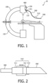
- an instrument tracking system 10 comprises an imaging system 100 used to acquire and display an image space showing anatomical structures proximate to an intervention procedure to be performed.
- the imaging system 100 may be a C-arm flat-detector CT imaging system as shown in Fig. 1 .
- the imaging system may be an MRI, CY, X-ray, ultrasound, or any other type of imaging system appropriate for acquiring images of anatomic structures for use in guiding an instrument during an intervention procedure.
- the imaging system 100 is an imaging system capable of providing a three-dimensional image volume.
- the instrument tracking system 10 also comprises an instrument 200 for use in an intervention procedure.
- the instrument may be any instrument used during an intervention, including but not limited to: a mechanical scalpel (lancet), a laser scalpel, an endoscope, microscopic imaging probes, a surgical stapler, a retractor, a cautery device (electrical or optical), a catheter, a chisel, a clamp, a probe, a trocar, scissors, or the like.
- the instrument 200 is manipulated by a physician to perform an intervention procedure. In many intervention procedures, a physician will use more than one instrument. Therefore, according to one embodiment, the instrument tracking system comprises more than one instrument.
- the instrument 200 (or one of the instruments) is connected to a connection point 101 on the imaging system 100 by a tether 300.
- the connection point 101 is a point that is registered to the coordinates of the image space of the imaging system 100.
- the connection point is at an optical connector 110.
- the optical connector 110 is fixed on the C-arm body of the CT imaging system.
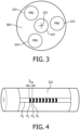
- the instrument 200 is connected to the tether 300 by a connector 310.
- the connector 300 uses clamping force to hold the instrument firmly in place.
- the connector 310 comprises a cylinder 311 fixedly connected to the tether 300 by crimping, adhesive, or any other appropriate fastening method.
- the cylinder may be plastic or any other suitable radiolucent structural material.
- the cylinder 311 has an external thread which is engaged with an internal thread on a collar 312.
- the collar may also be plastic or any other suitable radiolucent structural material.
- a tapered flexible wrap 313 extends into the collar opposite the tether 300 and is affixed to the cylinder 311 by adhesive, clamping, or any other suitable fixation method.
- the flexible wrap may be rubber or any other radiolucent flexible material suitable for deforming and clamping an instrument.
- the instrument 200 is placed into the open tapered flexible wrap 313 and may be abutted to a flange on the cylinder 311 for precision location of the instrument 200 relative to the tether 300.
- the collar 312 is rotated about the cylinder 311 advancing the collar 312 along its axis away from the tether 300 and pressing on the tapered flexible wrap 313 to securely hold the instrument 200 in place.
- the connector 310 allows a physician to attach any one of a plurality of instruments 200 to the tether 300. Moreover, the connector 310 allows the physician to change instruments during an intervention procedure, as will be described hereafter.
- the instrument 200 may be connected to the tether 300 by adhesive, a magnetic connection, threaded engagement of the instrument directly to the tether 300 or a threaded member attached to the tether, or any other suitable connection method.
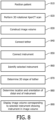
- the tether 300 comprises optical fiber cores 324 ( Fig. 3 ), which together with an optical console 400 ( Fig. 1 ) form a shape sensing system 320 that provides strain information. This strain information can be used to determine the precise location of the instrument 200 and to present the instrument location on an image from the imaging system 100.
- At least one and preferably four optical fibers 324 extend along the tether axis 325 as shown in Fig. 3 .
- one fiber core is on-axis and the others arranged in a helical fashion around the on-axis fiber core.
- the four cores could either be contained within a single fiber (thereby sharing the cladding) or in separate fibers mechanically connected (e.g. glued).
- the optical fibers 324 are symmetrically arranged around the tether axis 325.
- a plurality of optical scatterers are provided in the optical fiber cores or claddings in a plurality of locations along the length of the tether 300 (a single Fiber Bragg grating is shown in Fig. 4 ).
- a Fiber Bragg Grating is a segment of an optical fiber that reflects particular wavelengths of light and transmits all other wavelengths of light. This is achieved by adding a periodic variation of the refractive index in the fiber core, which generates a wavelength-specific dielectric mirror.
- a Fiber Bragg Grating can therefore be used as an inline optical filter to block certain wavelengths, or as a wavelength-specific reflector.
- the core of the optical fiber 324 has a refractive index of n 2 along most of its length. However, the refractive index is periodically changed to a different refractive index n 3 at a spacing of ⁇ B /2n eff (where n eff is the effective refractive index of the optical mode).
- Figs. 5A - 5C show the spectral response of a broadband light signal to the Bragg Grating. As shown in Fig. 5A , a broad spectrum light signal is input to the optical fiber 324. The light is split into light that is not at a wavelength ⁇ B which is transmitted through the Bragg Grating (shown in Fig. 5B ) and light at a wavelength of ⁇ B which is reflected by the Bragg Grating (shown in Fig. 5C ).
- Fiber Bragg Gratings involve Fresnel reflections at each of the interfaces where the refractive index changes. For some wavelengths, the reflected light of the various periods is in phase with one another so that constructive interference exists for reflection and consequently, destructive interference for transmission.
- the Bragg wavelength is sensitive to strain as well as to temperature. This means that Bragg gratings can be used as sensing elements in fiber optic sensors.
- the measurand causes a shift in the Bragg wavelength ⁇ B .
- the coefficient C S is called the coefficient of strain and its magnitude is usually around 0.8 X 10 -6 / ⁇ (or in absolute quantities about 1 pm/ ⁇ ).
- the coefficient C T describes the temperature sensitivity of the sensor; it is made up of the thermal expansion coefficient and the thermo-optic effect. Its value is around 7 X 10 -6 /K (or in absolute quantity 13 pm/K).
- a plurality of optical scatterers 330 can be distributed over the length of an optical fiber in the core or cladding to form sensors or gauges to measure strain. Incorporating at least four fiber optic cores with various sensors (gauges) along the length of a fiber that is embedded in a structure allows for the three-dimensional form of the structure to be precisely determined. As shown in Fig. 6 , scatterers 330 are located at each of a plurality of positions along the length of the tether 300. The local curvature of the tether 300 can be determined from the length-resolved strain and curvature measurements acquired from the tether 300. The total three-dimensional form of the tether 300 is determined from the plurality of strain and curvature measurements.
- the local curvature of the tether 300 can be determined from the length-resolved strain and curvature measurements acquired from the tether 300.
- multiple tethers can be used to simultaneously track multiple instruments in the coordinates of the image volume acquired from the imaging system 100.
- an optical console 400 is connected to the optical fiber cores 324 of the tether 300 at the connection point 101.
- the optical console is mounted within the C-arm body of the imaging system 100.
- the optical console 400 delivers light to the optical fibers and/or fiber optic cores and receives light from them.
- the optical console 400 can determine the Bragg wavelength ⁇ B for different portions of each Fiber Bragg Grating 322.
- an attachment means 150 is disposed on the C-arm of the imaging system 100 to secure the loose end of the tether 300 during rotational scans.
- the attachment means may be any mechanical connection device suitable for securing the tether 300.
- FIG. 7 is a block diagram of the instrument guidance system 10 shown in Fig. 1 .
- a processing unit 500 comprises a processor 510 which is operably connected to a memory 520. According to one embodiment, they are connected through a bus 530.
- the processor 510 may be may be any device capable of executing program instructions, such as one or more microprocessors.
- the memory may be any volatile or non-volatile memory device, such as a removable disc, a hard drive, a CD, a Random Access Memory (RAM), a Read Only Memory (ROM), or the like.
- a display 540 is also operably connected to the processor 510.
- the display may be any monitor, screen, or the like suitable for presenting a graphical user interface (GUI) capable of presenting medical images.
- GUI graphical user interface
- An imaging unit 120 such as the C-arm 102 (in Fig. 1 ) of an imaging system 100, is operably connected to the processor 510.
- the imaging unit provides imaging data to the processor 510 for processing to create an image volume of anatomical features.
- the image volume is then presented on the display 540.
- the processing unit 500 and the imaging unit 120 together form an imaging system 100.
- a shape determining unit 550 provides strain and curvature data from the tether 300 to the processor 510.
- the shape determining unit comprises the optical shape sensor (including optical fiber cores 324 that are located in the tether 300 along its longitudinal axis 325).
- the shape determining unit 550 further comprises an optical console 400, which interrogates the optical fiber cores sending a broadband light signal along each optical fiber core and measuring the reflected wavelengths to determine length-resolved strain and curvature in each optical fiber core.
- the reflection spectrum may be obtained from a narrow band light source whereby the wavelength is swept in time.
- the localized curvatures are used to determine the shape of the tether 300 within the image space.
- the optical console 400 may have a processor (not shown) separate from the processor 510 in the processing unit 500. Moreover, the optical module 400 may perform some or all of the calculations for wavelength shift, strain, and curvature; and provide wavelength measurements, shift calculations, strain calculations, or curvature data to the processor 510.
- the processor 510 processes imaging data to form an image space which is presented on the display 540.
- the data from the shape determining unit 550 is processed, as necessary to calculate curvatures over the length of the tether 300. This shape data is used by the processor 510, together with the known registration point at the fixed end of the tether 300 ( Fig. 1 ) to determine the location and orientation of the tether 300 at the connection 310, and therefore the location and orientation of the instrument 200 in the image space.
- An Instrument Identification Unit (IIU) 560 is operably connected to the processor 510 in the processing unit 500.
- the IIU 560 comprises means for identifying one of a plurality of instruments 200 in use by a physician during an intervention procedure.
- the identifying means may comprise a Radio Frequency Identification (RFID) receiver, with each instrument 200 or its packaging having an RFID transmitter attached to it.
- the identifying means may be a bar code reader, with each instrument 200 or its packaging having a bar code printed on it.
- a resistance code or microchip may be embedded in or attached to each instrument 200.
- the identifying means may be a keyboard or keypad, with the physician manually entering an identification indication, such as a code, or selecting from a menu, or the like.
- the identifying means may be integral with the connector 310 such that the identification information is transmitted through the tether 300.
- the identifying means may be disposed at another location, such as the processing unit with the instrument 200 brought to the identifying means for identification.
- FIG. 8 a flow diagram is shown for a method for dynamically tracking an instrument in an image space.
- a patient is positioned on an imaging system 100 (step 810). Patient positioning is performed according to known procedures in the art. According to one embodiment, the patient is positioned on an XperCT imaging system within the C-arm body as shown in Fig. 1 .
- a three-dimensional rotational XperCT scan is performed on the patient (step 820).
- the scan is performed according to known procedures in the art. It should be understood that alternate embodiments are contemplated using forms of imaging other than the three-dimensional rotational XperCT scan. Moreover, a scan may be performed before a procedure, during a procedure, or both.
- the processor 510 constructs an image volume from the scan data (step 830).
- the image volume is constructed using procedures known in the art showing anatomical structures.
- connection point 101 is a location that can be registered to the image volume. That is, the location of the connection point is known relative to the image volume.
- An optical connector 110 is provided at the connection point 101.
- the connection point 101 is located on the C-arm body of a XperCT imaging system.
- a connection point may be at a source or detector for an imaging system.
- the physician connects the tether 300 to the imaging system 100 (step 850).
- the tether is installed in the optical connector 110, which is connected by optical fibers to the optical console 400.
- the tether 300 is connected after the scan is performed.
- the tether 300 is connected prior to a scan and secured to the imaging system 100 at its distal end using attachment means 150.
- An instrument identification unit 560 identifies a selected instrument 200 (step 860).
- the instrument identification unit 560 may be an RFID receiver, a bar code reader, a keyboard or keypad, an electrical sensor, or any other means suitable for providing a code or signal to indicate a selected one of a plurality of instruments 200.
- the RFID transmitter, bar code, or the like may be provided on the selected instrument 200 or on its packaging.
- the physician takes the instrument 200 or packaging with the RFID transmitter and places it in proximity to the RFID receiver of the instrument identification unit 560.
- the RFID receiver of the instrument identification unit 560 receives the RFID signal and transmits the RFID code to the processor 510.
- a processor separate from the imaging processor 510 may receive the identification code.
- the physician enters an instrument 200 identification code using a keyboard, keypad, or the like.
- the processor 510 determines the shape of the tether 300 (step 870). Using known calculation methods, the known connection point 101, and the curvature data from each sensor triplet 330 along the length of the tether 300, the imaging processor 510 calculates the complete three-dimensional shape of the tether and registers it to the image volume. According to alternate embodiments, a processor separate from the image processor 510 determines the shape of the tether 300. Also, according to various embodiments, the strain calculations and curvature calculations may be performed by the imaging processor 510, another processor, or a combination thereof.
- the processor could calculate the complete three-dimensional shape of a portion of the tether that is clinically relevant; this portion of the tether could be localized relative to the imaging system or another structure by means of one or more markers that are positioned on the tether and tracked with known methods that do not involve the optical fibers or optical fiber cores described in this invention (e.g. EM tracking).
- the processor 510 determines the location and orientation of the functional part of the selected instrument 200 (step 880). Once the three-dimensional shape of the tether, the connection point 101, and the identification of the selected instrument 200 are known, the image processor 510 determines the location of the functional part of the selected instrument 200 and the orientation of the selected instrument 200 in the image space. This determination is performed using a preprogrammed shape and size for the selected instrument 200.
- the processor 510 displays the image volume of the patient corresponding to the selected instrument showing the instrument in the image volume (step 890). Different views of the image volume would be more appropriate for different instruments 200. For example, for a procedure that involves a needle insertion, an image volume in which critical structures such as blood vessels are segmented and highlighted might be appropriate. As another example, for a procedure that involves removing brain tumor tissue with a scalpel or suction device, an image volume in which tumor tissue is segmented and highlighted might be appropriate.
- the processor 510 displays an image most useful or corresponding to which instrument 200 is selected. The processor 510 shows the selected instrument 200 in the image.
- the displayed image may be from a pre-procedural scan or a scan performed during a procedure.
- a pre-procedural image may be acquired using CT or MRI.
- the patient is moved to a surgical table, where an XperCT image is acquired (rotational C-arm scan).
- the XperCT image is co-registered with the CT and/or MRI images.
- Two-dimensional flouroscopic images may be acquired in real-time and registered with the pre-procedural and XperCT images, such as for tracking (or refining) the depth of a scalpel.
- no pre-procedural images are acquired.
- the patient is moved to a surgical table, where an XperCT image is acquired before the procedure starts (rotational C-arm scan), and potentially at different time points during the procedure.
- fluoroscopic images may be acquired in real-time and registered to the XperCT images.
- no pre-procedural images are acquired.
- the patient is moved to a surgical table with an open MRI.
- a MRI image is acquired before the procedure and potentially at different time points during the procedure.
- the functional part of the instrument 200 can be registered to any of the acquired images, because the tether 300 is fixed at a location that is defined relative to the images (being a fixed location on the imaging equipment) and the three-dimensional shape of the tether 300 can be calculated, giving the location of the instrument 200.
- the selected instrument 200 is identified, so that the size and shape can be retrieved from memory and used to determine the precise location of the functional part of the instrument.
- the selected instrument 200 may change during a procedure. For example, a physician may switch from a scalpel to a stapler. Since the new selected instrument 200 is identified, as previously described, the location of the functional part of the new selected instrument 200 can be determined with respect to the image space and an appropriate image can be presented showing the new selected instrument 200.
- At least one radio-opaque marker is disposed on the tether 300 or on the selected instrument 200.
- the radio-opaque marker is visible under two-dimensional fluoroscopy.
- 2D fluoroscopy is utilized during a surgical intervention, the position of the marker(s) in a plane perpendicular to the x-ray detector-emitter axis can be determined in real-time. This determination can be performed by digital analysis of the fluoroscopic images, using image pattern recognition algorithms that are well-known in the scientific community.
- the marker positions can be utilized as reference points to improve the accuracy at which the 3D shape of the tether 300 and location of the instrument 200 are calculated.
- At least one electromagnetic (EM) or optical marker is disposed on the tether 300 or on the selected instrument 200.
- the marker positions, as determined by EM or optical sensors, are utilized as reference points to improve the accuracy at which the 3D shape of the tether 300 and/or instrument 200 is calculated.
- a shape-sensing tether 300 is rigidly attached to a combined X-ray breast mammography / biopsy system 900.
- the tether is connected at either the X-ray source 910, the detector 920, the biopsy system, or any other rigid transformation point.
- Breast mammography systems are able to obtain depth information on tumor nodules by performing tomosynthesis imaging, which involves moving a camera and detector around an object (in this case a breast). Based on images created using this procedure, depth information on tumor location is obtained which is later used for guided or automated breast biopsy.
- a shape-sensing tether 300 Using a shape-sensing tether 300, a conventional, markerless, biopsy needle is tracked and placed with excellent accuracy based on the previously acquired tomosynthesis images. Since the tether 300 is mechanically connected to the combined imaging/biopsy system 900, the position of the instrument connector 310, and therefore the biopsy needle, as calculated with the shape determining algorithm is automatically registered to the coordinates of the tomosynthesis X-ray images.
- optical shape sensing system in this particular application has the significant advantage that it is not sensitive to EM distortions that occur when using EM tracking. EM distortions occur due to metal, which is omnipresent in current X-ray mammography/biopsy systems.
Applications Claiming Priority (2)
| Application Number | Priority Date | Filing Date | Title |
|---|---|---|---|
| US39113710P | 2010-10-08 | 2010-10-08 | |
| PCT/IB2011/054400 WO2012046202A1 (en) | 2010-10-08 | 2011-10-06 | Flexible tether with integrated sensors for dynamic instrument tracking |
Publications (2)
| Publication Number | Publication Date |
|---|---|
| EP2624780A1 EP2624780A1 (en) | 2013-08-14 |
| EP2624780B1 true EP2624780B1 (en) | 2024-02-14 |
Family
ID=44898092
Family Applications (1)
| Application Number | Title | Priority Date | Filing Date |
|---|---|---|---|
| EP11776549.5A Active EP2624780B1 (en) | 2010-10-08 | 2011-10-06 | Flexible tether with integrated sensors for dynamic instrument tracking |
Country Status (6)
| Country | Link |
|---|---|
| US (1) | US9757034B2 (ja) |
| EP (1) | EP2624780B1 (ja) |
| JP (1) | JP5944395B2 (ja) |
| CN (1) | CN103153223B (ja) |
| RU (1) | RU2597136C2 (ja) |
| WO (1) | WO2012046202A1 (ja) |
Families Citing this family (49)
| Publication number | Priority date | Publication date | Assignee | Title |
|---|---|---|---|---|
| ES2569411T3 (es) | 2006-05-19 | 2016-05-10 | The Queen's Medical Center | Sistema de seguimiento de movimiento para imágenes adaptativas en tiempo real y espectroscopia |
| US9606209B2 (en) | 2011-08-26 | 2017-03-28 | Kineticor, Inc. | Methods, systems, and devices for intra-scan motion correction |
| US9405085B2 (en) | 2011-10-26 | 2016-08-02 | Koninklijke Philips N.V. | Smart tool holder for an optical shape-sensing fiber |
| RU2014143669A (ru) * | 2012-03-29 | 2016-05-27 | Конинклейке Филипс Н.В. | Устранение искажений с использованием считывания формы |
| CN104411248B (zh) * | 2012-06-28 | 2017-09-26 | 皇家飞利浦有限公司 | 在内窥镜外科手术中用于最佳图像采集的c型臂轨迹规划 |
| JP6255394B2 (ja) | 2012-07-09 | 2017-12-27 | コーニンクレッカ フィリップス エヌ ヴェKoninklijke Philips N.V. | 適応的な画像によりガイドされた介入のための方法及びシステム |
| ITBO20120479A1 (it) * | 2012-09-12 | 2014-03-13 | Sintea Plustek S R L | Dispositivo retrattore sensorizzato per tessuti in interventi chirurgici |
| RU2638445C2 (ru) * | 2012-10-01 | 2017-12-13 | Конинклейке Филипс Н.В. | Трехмерное полилинейное совмещение с использованием ограничений формы |
| US9305365B2 (en) | 2013-01-24 | 2016-04-05 | Kineticor, Inc. | Systems, devices, and methods for tracking moving targets |
| US9717461B2 (en) | 2013-01-24 | 2017-08-01 | Kineticor, Inc. | Systems, devices, and methods for tracking and compensating for patient motion during a medical imaging scan |
| US10327708B2 (en) | 2013-01-24 | 2019-06-25 | Kineticor, Inc. | Systems, devices, and methods for tracking and compensating for patient motion during a medical imaging scan |
| CN105392423B (zh) | 2013-02-01 | 2018-08-17 | 凯内蒂科尔股份有限公司 | 生物医学成像中的实时适应性运动补偿的运动追踪系统 |
| CN105338919B (zh) * | 2013-06-28 | 2018-08-28 | 皇家飞利浦有限公司 | 利用多条光纤的光学形状感测 |
| WO2015049612A2 (en) * | 2013-10-02 | 2015-04-09 | Koninklijke Philips N.V. | Hub design and methods for optical shape sensing registration |
| US20160228200A1 (en) * | 2013-10-02 | 2016-08-11 | Koninklijke Philips N.V. | Device tracking using longitudinal encoding |
| US10004462B2 (en) | 2014-03-24 | 2018-06-26 | Kineticor, Inc. | Systems, methods, and devices for removing prospective motion correction from medical imaging scans |
| WO2016014718A1 (en) | 2014-07-23 | 2016-01-28 | Kineticor, Inc. | Systems, devices, and methods for tracking and compensating for patient motion during a medical imaging scan |
| US9754372B2 (en) * | 2014-08-15 | 2017-09-05 | Biosense Webster (Israel) Ltd. | Marking of fluoroscope field-of-view |
| JP6894836B2 (ja) * | 2014-09-08 | 2021-06-30 | コーニンクレッカ フィリップス エヌ ヴェKoninklijke Philips N.V. | 整形外科における器具追跡のための光形状検知 |
| CN106999209B (zh) * | 2014-12-01 | 2020-08-18 | 皇家飞利浦有限公司 | 光学形状感测工具的配准 |
| GB2536650A (en) | 2015-03-24 | 2016-09-28 | Augmedics Ltd | Method and system for combining video-based and optic-based augmented reality in a near eye display |
| EP3307193A1 (en) | 2015-06-12 | 2018-04-18 | Koninklijke Philips N.V. | Universal fiber-optical realshape insert |
| EP3316786B1 (en) * | 2015-06-30 | 2019-09-11 | Koninklijke Philips N.V. | Fiber-optical realshape sensing for fluoroscopic surgical navigation |
| US9943247B2 (en) | 2015-07-28 | 2018-04-17 | The University Of Hawai'i | Systems, devices, and methods for detecting false movements for motion correction during a medical imaging scan |
| JP6945293B2 (ja) * | 2015-11-16 | 2021-10-06 | キヤノンメディカルシステムズ株式会社 | X線診断装置および医用画像診断システム |
| WO2017091479A1 (en) | 2015-11-23 | 2017-06-01 | Kineticor, Inc. | Systems, devices, and methods for tracking and compensating for patient motion during a medical imaging scan |
| WO2017115201A1 (en) * | 2015-12-29 | 2017-07-06 | Koninklijke Philips N.V. | Registration system for medical navigation and method of operation thereof |
| JP6828047B2 (ja) | 2016-02-12 | 2021-02-10 | インテュイティブ サージカル オペレーションズ, インコーポレイテッド | 画像誘導手術における透視撮像システムの姿勢推定及び較正のシステム及び方法 |
| CN109310405B (zh) | 2016-05-10 | 2022-04-05 | 皇家飞利浦有限公司 | 活检容器 |
| JP6717713B2 (ja) * | 2016-08-31 | 2020-07-01 | テルモ株式会社 | 医療用デバイス |
| WO2018096491A1 (en) | 2016-11-28 | 2018-05-31 | Koninklijke Philips N.V. | Shape sensing of multiple over-the-wire devices |
| US20200359112A1 (en) * | 2017-12-11 | 2020-11-12 | Drägerwerk AG & Co. KGaA | Cable manager |
| CN108577977B (zh) * | 2018-03-19 | 2020-10-30 | 山东大学 | 穿刺针及穿刺针运动轨迹的三维重建方法及系统 |
| WO2019211741A1 (en) | 2018-05-02 | 2019-11-07 | Augmedics Ltd. | Registration of a fiducial marker for an augmented reality system |
| US11766296B2 (en) | 2018-11-26 | 2023-09-26 | Augmedics Ltd. | Tracking system for image-guided surgery |
| EP4013338A4 (en) | 2019-08-12 | 2023-08-30 | Bard Access Systems, Inc. | FORM MEASUREMENT SYSTEMS AND PROCESSES FOR MEDICAL DEVICES |
| US11525670B2 (en) | 2019-11-25 | 2022-12-13 | Bard Access Systems, Inc. | Shape-sensing systems with filters and methods thereof |
| EP4061466A4 (en) | 2019-11-25 | 2023-11-22 | Bard Access Systems, Inc. | ADVANCED OPTICAL TRACKING SYSTEMS AND THEIR METHODS |
| US11382712B2 (en) | 2019-12-22 | 2022-07-12 | Augmedics Ltd. | Mirroring in image guided surgery |
| EP4110176A1 (en) * | 2020-02-28 | 2023-01-04 | Bard Access Systems, Inc. | Catheter with optic shape sensing capabilities |
| CN113325524A (zh) | 2020-02-28 | 2021-08-31 | 巴德阿克塞斯系统股份有限公司 | 光学连接系统及其方法 |
| CN113456054A (zh) | 2020-03-30 | 2021-10-01 | 巴德阿克塞斯系统股份有限公司 | 光学和电气诊断系统及其方法 |
| CN216319408U (zh) | 2020-06-26 | 2022-04-19 | 巴德阿克塞斯系统股份有限公司 | 错位检测系统 |
| CN216136534U (zh) | 2020-06-29 | 2022-03-29 | 巴德阿克塞斯系统股份有限公司 | 用于将医疗装置放置入患者身体内的医疗装置系统 |
| CN113907705A (zh) | 2020-07-10 | 2022-01-11 | 巴德阿克塞斯系统股份有限公司 | 连续光纤功能监测和自诊断报告系统 |
| CN114052658A (zh) | 2020-08-03 | 2022-02-18 | 巴德阿克塞斯系统股份有限公司 | 布拉格光栅光纤波动感测与监测系统 |
| WO2022081586A1 (en) | 2020-10-13 | 2022-04-21 | Bard Access Systems, Inc. | Disinfecting covers for functional connectors of medical devices and methods thereof |
| CN113349928B (zh) * | 2021-05-20 | 2023-01-24 | 清华大学 | 用于柔性器械的增强现实手术导航装置 |
| US11896445B2 (en) | 2021-07-07 | 2024-02-13 | Augmedics Ltd. | Iliac pin and adapter |
Citations (1)
| Publication number | Priority date | Publication date | Assignee | Title |
|---|---|---|---|---|
| US20100249506A1 (en) * | 2009-03-26 | 2010-09-30 | Intuitive Surgical, Inc. | Method and system for assisting an operator in endoscopic navigation |
Family Cites Families (33)
| Publication number | Priority date | Publication date | Assignee | Title |
|---|---|---|---|---|
| US4821727A (en) * | 1986-10-30 | 1989-04-18 | Elscint Ltd. | Mammographic biopsy needle holder system |
| US5638819A (en) | 1995-08-29 | 1997-06-17 | Manwaring; Kim H. | Method and apparatus for guiding an instrument to a target |
| US6346940B1 (en) | 1997-02-27 | 2002-02-12 | Kabushiki Kaisha Toshiba | Virtualized endoscope system |
| US6522906B1 (en) | 1998-12-08 | 2003-02-18 | Intuitive Surgical, Inc. | Devices and methods for presenting and regulating auxiliary information on an image display of a telesurgical system to assist an operator in performing a surgical procedure |
| US6466815B1 (en) | 1999-03-30 | 2002-10-15 | Olympus Optical Co., Ltd. | Navigation apparatus and surgical operation image acquisition/display apparatus using the same |
| JP4116757B2 (ja) * | 1999-08-24 | 2008-07-09 | オリンパス株式会社 | 電気処置システム |
| US8221402B2 (en) * | 2000-01-19 | 2012-07-17 | Medtronic, Inc. | Method for guiding a medical device |
| DE10004764A1 (de) | 2000-02-03 | 2001-08-09 | Philips Corp Intellectual Pty | Verfahren zur Positionsbestimmung eines medizinischen Instruments |
| US6856827B2 (en) * | 2000-04-28 | 2005-02-15 | Ge Medical Systems Global Technology Company, Llc | Fluoroscopic tracking and visualization system |
| AU2001292836A1 (en) | 2000-09-23 | 2002-04-02 | The Board Of Trustees Of The Leland Stanford Junior University | Endoscopic targeting method and system |
| US6663559B2 (en) | 2001-12-14 | 2003-12-16 | Endactive, Inc. | Interface for a variable direction of view endoscope |
| WO2004039249A1 (ja) | 2002-10-29 | 2004-05-13 | Olympus Corporation | 内視鏡情報の処理装置および処理方法 |
| JP2004208922A (ja) | 2002-12-27 | 2004-07-29 | Olympus Corp | 医療装置及び医療用マニピュレータ並びに医療装置の制御方法 |
| US7027699B2 (en) * | 2003-05-21 | 2006-04-11 | The Hong Kong Polytechnic University | Optical fiber and optical fiber sensors |
| US7319877B2 (en) * | 2003-07-22 | 2008-01-15 | Microsoft Corporation | Methods for determining the approximate location of a device from ambient signals |
| US7232409B2 (en) | 2003-11-20 | 2007-06-19 | Karl Storz Development Corp. | Method and apparatus for displaying endoscopic images |
| US7772541B2 (en) * | 2004-07-16 | 2010-08-10 | Luna Innnovations Incorporated | Fiber optic position and/or shape sensing based on rayleigh scatter |
| US20060013523A1 (en) | 2004-07-16 | 2006-01-19 | Luna Innovations Incorporated | Fiber optic position and shape sensing device and method relating thereto |
| US7643862B2 (en) * | 2005-09-15 | 2010-01-05 | Biomet Manufacturing Corporation | Virtual mouse for use in surgical navigation |
| US7930065B2 (en) | 2005-12-30 | 2011-04-19 | Intuitive Surgical Operations, Inc. | Robotic surgery system including position sensors using fiber bragg gratings |
| JP5085996B2 (ja) | 2006-10-25 | 2012-11-28 | テルモ株式会社 | マニピュレータシステム |
| CN101534714B (zh) * | 2006-11-03 | 2013-09-25 | 皇家飞利浦电子股份有限公司 | 多重旋转的c形臂 |
| WO2008097540A2 (en) | 2007-02-02 | 2008-08-14 | Hansen Medical, Inc. | Robotic surgical instrument and methods using bragg fiber sensors |
| WO2008115375A1 (en) * | 2007-03-16 | 2008-09-25 | Luna Innovations Incorporated | Fiber optic position and/or shape sensing based on rayleigh scatter |
| EP2626027B1 (en) | 2007-08-14 | 2020-04-29 | Koninklijke Philips N.V. | Robotic instrument systems utilizing optical fiber sensors |
| US7720322B2 (en) | 2008-06-30 | 2010-05-18 | Intuitive Surgical, Inc. | Fiber optic shape sensor |
| US20100030063A1 (en) * | 2008-07-31 | 2010-02-04 | Medtronic, Inc. | System and method for tracking an instrument |
| EP2165671B1 (de) * | 2008-09-19 | 2011-06-01 | BrainLAB AG | Chirurgisches Pointerinstrument mit Spitzensensor |
| JP5259340B2 (ja) | 2008-10-28 | 2013-08-07 | オリンパスメディカルシステムズ株式会社 | 医療機器 |
| US8337397B2 (en) * | 2009-03-26 | 2012-12-25 | Intuitive Surgical Operations, Inc. | Method and system for providing visual guidance to an operator for steering a tip of an endoscopic device toward one or more landmarks in a patient |
| WO2010111090A1 (en) * | 2009-03-26 | 2010-09-30 | Intuitive Surgical Operations, Inc. | System for providing visual guidance for steering a tip of an endoscopic device towards one or more landmarks and assisting an operator in endoscopic navigation |
| US8183520B2 (en) * | 2009-11-13 | 2012-05-22 | Intuitive Surgical Operations, Inc. | Optical fiber shape sensor calibration |
| US9285246B2 (en) * | 2010-02-12 | 2016-03-15 | Intuitive Surgical Operations, Inc. | Method and system for absolute three-dimensional measurements using a twist-insensitive shape sensor |
-
2011
- 2011-10-06 WO PCT/IB2011/054400 patent/WO2012046202A1/en active Application Filing
- 2011-10-06 RU RU2013120967/14A patent/RU2597136C2/ru not_active IP Right Cessation
- 2011-10-06 EP EP11776549.5A patent/EP2624780B1/en active Active
- 2011-10-06 CN CN201180048443.2A patent/CN103153223B/zh active Active
- 2011-10-06 US US13/877,343 patent/US9757034B2/en active Active
- 2011-10-06 JP JP2013532306A patent/JP5944395B2/ja active Active
Patent Citations (1)
| Publication number | Priority date | Publication date | Assignee | Title |
|---|---|---|---|---|
| US20100249506A1 (en) * | 2009-03-26 | 2010-09-30 | Intuitive Surgical, Inc. | Method and system for assisting an operator in endoscopic navigation |
Also Published As
| Publication number | Publication date |
|---|---|
| RU2597136C2 (ru) | 2016-09-10 |
| RU2013120967A (ru) | 2014-11-20 |
| US20130188855A1 (en) | 2013-07-25 |
| EP2624780A1 (en) | 2013-08-14 |
| WO2012046202A1 (en) | 2012-04-12 |
| JP5944395B2 (ja) | 2016-07-05 |
| US9757034B2 (en) | 2017-09-12 |
| CN103153223B (zh) | 2016-09-14 |
| JP2013542768A (ja) | 2013-11-28 |
| CN103153223A (zh) | 2013-06-12 |
Similar Documents
| Publication | Publication Date | Title |
|---|---|---|
| EP2624780B1 (en) | Flexible tether with integrated sensors for dynamic instrument tracking | |
| JP2013542768A5 (ja) | ||
| EP2523593B1 (en) | Flexible instrument channel insert for scope with real-time position tracking | |
| CN108601628B (zh) | 将操作器械定位在患者身体内的导航、跟踪和引导系统 | |
| JP6226751B2 (ja) | インターベンショナル環境内への光ファイバ形状検知の統合 | |
| CN107072743B (zh) | 被布置为与光学形状感测使能的介入设备协作的处理系统 | |
| CN115813552A (zh) | 利用光学形状感测光纤触发 | |
| CN102892347A (zh) | 快速的光纤的形状重建 | |
| CN105555205A (zh) | 用于定位可移动目标的形状传感器系统 | |
| WO2012101555A1 (en) | Shape sensing device-specific information storage and retrieval | |
| US20170265946A1 (en) | Shape sensed robotic ultrasound for minimally invasive interventions | |
| US10952810B2 (en) | Method and system for adaptive image guided intervention | |
| US20210186648A1 (en) | Surgical shape sensing fiber optic apparatus and method thereof | |
| CA2955036C (en) | Tip deformation measuring apparatus for medical procedures | |
| US10267624B2 (en) | System and method for reconstructing a trajectory of an optical fiber | |
| US8067726B2 (en) | Universal instrument calibration system and method of use |
Legal Events
| Date | Code | Title | Description |
|---|---|---|---|
| PUAI | Public reference made under article 153(3) epc to a published international application that has entered the european phase |
Free format text: ORIGINAL CODE: 0009012 |
|
| 17P | Request for examination filed |
Effective date: 20130508 |
|
| AK | Designated contracting states |
Kind code of ref document: A1 Designated state(s): AL AT BE BG CH CY CZ DE DK EE ES FI FR GB GR HR HU IE IS IT LI LT LU LV MC MK MT NL NO PL PT RO RS SE SI SK SM TR |
|
| RAP1 | Party data changed (applicant data changed or rights of an application transferred) |
Owner name: KONINKLIJKE PHILIPS N.V. |
|
| DAX | Request for extension of the european patent (deleted) | ||
| STAA | Information on the status of an ep patent application or granted ep patent |
Free format text: STATUS: EXAMINATION IS IN PROGRESS |
|
| 17Q | First examination report despatched |
Effective date: 20170503 |
|
| RAP1 | Party data changed (applicant data changed or rights of an application transferred) |
Owner name: KONINKLIJKE PHILIPS N.V. |
|
| STAA | Information on the status of an ep patent application or granted ep patent |
Free format text: STATUS: EXAMINATION IS IN PROGRESS |
|
| STAA | Information on the status of an ep patent application or granted ep patent |
Free format text: STATUS: EXAMINATION IS IN PROGRESS |
|
| REG | Reference to a national code |
Ref country code: DE Ref legal event code: R079 Free format text: PREVIOUS MAIN CLASS: A61B0019000000 Ipc: A61B0005000000 Ref country code: DE Ref legal event code: R079 Ref document number: 602011074572 Country of ref document: DE Free format text: PREVIOUS MAIN CLASS: A61B0019000000 Ipc: A61B0005000000 |
|
| GRAP | Despatch of communication of intention to grant a patent |
Free format text: ORIGINAL CODE: EPIDOSNIGR1 |
|
| STAA | Information on the status of an ep patent application or granted ep patent |
Free format text: STATUS: GRANT OF PATENT IS INTENDED |
|
| RIC1 | Information provided on ipc code assigned before grant |
Ipc: A61B 90/98 20160101ALI20230918BHEP Ipc: A61B 34/20 20160101ALI20230918BHEP Ipc: A61B 17/34 20060101ALI20230918BHEP Ipc: A61B 6/00 20060101ALI20230918BHEP Ipc: A61B 5/00 20060101AFI20230918BHEP |
|
| INTG | Intention to grant announced |
Effective date: 20231006 |
|
| RIN1 | Information on inventor provided before grant (corrected) |
Inventor name: HALL, CHRISTOPHER, STEPHEN Inventor name: SHECHTER, GUY Inventor name: MANZKE, ROBERT Inventor name: CHAN, RAYMOND Inventor name: 'T HOOFT, GERT, WIM Inventor name: DESJARDINS, ADRIEN, EMMANUEL |
|
| GRAS | Grant fee paid |
Free format text: ORIGINAL CODE: EPIDOSNIGR3 |
|
| GRAA | (expected) grant |
Free format text: ORIGINAL CODE: 0009210 |
|
| STAA | Information on the status of an ep patent application or granted ep patent |
Free format text: STATUS: THE PATENT HAS BEEN GRANTED |
|
| AK | Designated contracting states |
Kind code of ref document: B1 Designated state(s): AL AT BE BG CH CY CZ DE DK EE ES FI FR GB GR HR HU IE IS IT LI LT LU LV MC MK MT NL NO PL PT RO RS SE SI SK SM TR |
|
| REG | Reference to a national code |
Ref country code: GB Ref legal event code: FG4D |
|
| REG | Reference to a national code |
Ref country code: CH Ref legal event code: EP |
|
| REG | Reference to a national code |
Ref country code: DE Ref legal event code: R096 Ref document number: 602011074572 Country of ref document: DE |
|
| REG | Reference to a national code |
Ref country code: IE Ref legal event code: FG4D |