EP2624371A2 - Hermetic feed-through with hybrid seal structure - Google Patents
Hermetic feed-through with hybrid seal structure Download PDFInfo
- Publication number
- EP2624371A2 EP2624371A2 EP20130166474 EP13166474A EP2624371A2 EP 2624371 A2 EP2624371 A2 EP 2624371A2 EP 20130166474 EP20130166474 EP 20130166474 EP 13166474 A EP13166474 A EP 13166474A EP 2624371 A2 EP2624371 A2 EP 2624371A2
- Authority
- EP
- European Patent Office
- Prior art keywords
- sealing
- housing body
- polymer
- glass
- layer
- Prior art date
- Legal status (The legal status is an assumption and is not a legal conclusion. Google has not performed a legal analysis and makes no representation as to the accuracy of the status listed.)
- Granted
Links
Images




Classifications
-
- H—ELECTRICITY
- H01—ELECTRIC ELEMENTS
- H01R—ELECTRICALLY-CONDUCTIVE CONNECTIONS; STRUCTURAL ASSOCIATIONS OF A PLURALITY OF MUTUALLY-INSULATED ELECTRICAL CONNECTING ELEMENTS; COUPLING DEVICES; CURRENT COLLECTORS
- H01R13/00—Details of coupling devices of the kinds covered by groups H01R12/70 or H01R24/00 - H01R33/00
- H01R13/46—Bases; Cases
- H01R13/52—Dustproof, splashproof, drip-proof, waterproof, or flameproof cases
- H01R13/521—Sealing between contact members and housing, e.g. sealing insert
-
- G—PHYSICS
- G11—INFORMATION STORAGE
- G11B—INFORMATION STORAGE BASED ON RELATIVE MOVEMENT BETWEEN RECORD CARRIER AND TRANSDUCER
- G11B33/00—Constructional parts, details or accessories not provided for in the other groups of this subclass
- G11B33/12—Disposition of constructional parts in the apparatus, e.g. of power supply, of modules
- G11B33/121—Disposition of constructional parts in the apparatus, e.g. of power supply, of modules the apparatus comprising a single recording/reproducing device
- G11B33/123—Mounting arrangements of constructional parts onto a chassis
-
- H—ELECTRICITY
- H02—GENERATION; CONVERSION OR DISTRIBUTION OF ELECTRIC POWER
- H02G—INSTALLATION OF ELECTRIC CABLES OR LINES, OR OF COMBINED OPTICAL AND ELECTRIC CABLES OR LINES
- H02G3/00—Installations of electric cables or lines or protective tubing therefor in or on buildings, equivalent structures or vehicles
- H02G3/22—Installations of cables or lines through walls, floors or ceilings, e.g. into buildings
-
- A—HUMAN NECESSITIES
- A61—MEDICAL OR VETERINARY SCIENCE; HYGIENE
- A61N—ELECTROTHERAPY; MAGNETOTHERAPY; RADIATION THERAPY; ULTRASOUND THERAPY
- A61N1/00—Electrotherapy; Circuits therefor
- A61N1/18—Applying electric currents by contact electrodes
- A61N1/32—Applying electric currents by contact electrodes alternating or intermittent currents
- A61N1/36—Applying electric currents by contact electrodes alternating or intermittent currents for stimulation
- A61N1/372—Arrangements in connection with the implantation of stimulators
- A61N1/375—Constructional arrangements, e.g. casings
- A61N1/3752—Details of casing-lead connections
- A61N1/3754—Feedthroughs
-
- H—ELECTRICITY
- H01—ELECTRIC ELEMENTS
- H01R—ELECTRICALLY-CONDUCTIVE CONNECTIONS; STRUCTURAL ASSOCIATIONS OF A PLURALITY OF MUTUALLY-INSULATED ELECTRICAL CONNECTING ELEMENTS; COUPLING DEVICES; CURRENT COLLECTORS
- H01R13/00—Details of coupling devices of the kinds covered by groups H01R12/70 or H01R24/00 - H01R33/00
- H01R13/02—Contact members
- H01R13/03—Contact members characterised by the material, e.g. plating, or coating materials
-
- H—ELECTRICITY
- H01—ELECTRIC ELEMENTS
- H01R—ELECTRICALLY-CONDUCTIVE CONNECTIONS; STRUCTURAL ASSOCIATIONS OF A PLURALITY OF MUTUALLY-INSULATED ELECTRICAL CONNECTING ELEMENTS; COUPLING DEVICES; CURRENT COLLECTORS
- H01R13/00—Details of coupling devices of the kinds covered by groups H01R12/70 or H01R24/00 - H01R33/00
- H01R13/46—Bases; Cases
- H01R13/52—Dustproof, splashproof, drip-proof, waterproof, or flameproof cases
- H01R13/5216—Dustproof, splashproof, drip-proof, waterproof, or flameproof cases characterised by the sealing material, e.g. gels or resins
-
- Y—GENERAL TAGGING OF NEW TECHNOLOGICAL DEVELOPMENTS; GENERAL TAGGING OF CROSS-SECTIONAL TECHNOLOGIES SPANNING OVER SEVERAL SECTIONS OF THE IPC; TECHNICAL SUBJECTS COVERED BY FORMER USPC CROSS-REFERENCE ART COLLECTIONS [XRACs] AND DIGESTS
- Y10—TECHNICAL SUBJECTS COVERED BY FORMER USPC
- Y10T—TECHNICAL SUBJECTS COVERED BY FORMER US CLASSIFICATION
- Y10T29/00—Metal working
- Y10T29/49—Method of mechanical manufacture
- Y10T29/49002—Electrical device making
- Y10T29/49117—Conductor or circuit manufacturing
- Y10T29/49124—On flat or curved insulated base, e.g., printed circuit, etc.
- Y10T29/49155—Manufacturing circuit on or in base
Definitions
- the present disclosure relates to electric power terminals, and more particularly to hermetic feed-throughs of the electric power terminals with improved seal structures.
- Hermetically sealed electric power terminals generally include air-tight feed-throughs for use in conjunction with hermetically sealed devices.
- the feed-through includes a metal housing to be mounted on the hermetically sealed device, and a plurality of conductive pins extending through the metal housing for conducting electric current.
- a sealing material is generally provided between the metal housing and the conductive pins to electrically insulate the conductive pins from the metal housing.
- the sealing material hermetically seals the conductive pins to the metal housing to prohibit air leakage into or from the hermetically sealed device.
- a glass or polymer has been used as the sealing material in the feed-through to provide electric insulation and prevent gas permeation.
- the performance, cost or design flexibility of a glass or polymer may not be preferred for all purposes or environments or operating conditions.
- some sealing materials may be used with a limited number of metals. Therefore the selection of metals for the conductive pins and housings is likewise limited.
- a hermetic feed-through includes a housing body, a conductive pin, and a seal structure that seals the conductive pin to the housing body and that provides electric insulation between the housing body and the conductive pin.
- the seal structure includes a first material fused (e.g., bonded or sealed) to one of the housing body and the conductive pin, and a second material fused to the other one of the housing body and the conductive pin.
- a hermetic feed-through in another form, includes a housing body, a conductive pin, and a seal structure that seals the conductive pin to the housing body and that provides electric insulation between the housing body and the conductive pin.
- the seal structure includes a first material, a second material, and at least two of a first sealing path, a second sealing path, and a third sealing path.
- the first sealing path is a glass-to-metal seal.
- the second sealing path is a polymer-to-metal seal.
- the third sealing path is a polymer-to-glass seal.
- a method of manufacturing a feed-through includes: fusing a first material to at least one dummy pin to form a substrate; removing the at least one dummy pin from the substrate to form at least one opening corresponding to the dummy pin; inserting at least one conductive pin to the at least one opening; and fusing a second material to the at least one conductive pin.
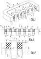
- FIG. 1 is a partial cross-sectional perspective view of an exemplary feed-through of a first embodiment of the present disclosure
- FIG. 2 is a cross-sectional view of the feed-through of FIG. 1 ;
- FIG. 3 is a schematic view illustrating sealing paths of the feed-through of FIG. 1 ;
- FIGS. 4A to FIG. 4D are cross-sectional views of the feed-through of FIG. 1 , illustrating sequential steps of manufacturing the feed-through of the first embodiment
- FIG. 5 is a partial cross-sectional perspective view of an exemplary feed-through of a second embodiment of the present disclosure
- FIG. 6 is a cross-sectional view of an exemplary feed-through of a second embodiment of the present disclosure.
- FIG. 7 is a schematic view illustrating sealing paths of the feed-through of FIG. 5 ;
- FIGS. 8A to 8D are cross-sectional views of the feed-through of FIG. 5 , illustrating sequential steps of manufacturing the feed-through;
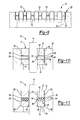
- FIG. 9 is a cross-sectional view of an exemplary feed-through in accordance with a third embodiment of the present disclosure.
- FIG. 10 is a schematic view illustrating sealing paths of a feed-through of a third embodiment
- FIG. 11 is a schematic view illustrating sealing paths of a variant of an exemplary feed-through of a third embodiment
- FIG. 12 is a partial cross-sectional perspective view of an exemplary feed-through in accordance with a fourth embodiment of the present disclosure.
- FIG. 13 is a cross-sectional view of a feed-through of the fourth embodiment
- FIG. 14 is a schematic view illustrating sealing paths of an exemplary feed-through of the fourth embodiment
- FIG. 15 is a cross-sectional view of an exemplary feed-through of the fifth embodiment of the present disclosure.
- FIG. 16 is a schematic view illustrating sealing paths of a feed-through of the fifth embodiment
- FIG. 17 is a cross-sectional view of a feed-through in accordance with a sixth embodiment of the present disclosure.
- FIG. 18 is a schematic view illustrating a sealing boundary of a feed-through of the sixth embodiment.
- FIG. 19 is a schematic view illustrating a sealing boundary of a feed-through in accordance with a seventh embodiment of the present disclosure.
- first, second, third, etc. may be used herein to describe various elements, components, regions, layers and/or sections, these elements, components, regions, layers and/or sections should not be limited by these terms. These terms may be only used to distinguish one element, component, region, layer or section from another region, layer or section. Terms such as “first,” “second,” and other numerical terms when used herein do not imply a sequence or order unless clearly indicated by the context. Thus, a first element, component, region, layer or section discussed below could be termed a second element, component, region, layer or section without departing from the teachings of the example embodiments.
- spatially relative terms such as “inner,” “oxter” “beneath”, “below”, “lower”, “above”, “upper” and the like, may be used herein for ease of description to describe one element or feature's relationship to another element(s) or feature(s) as illustrated in the figures.
- Spatially relative terms may be intended to encompass different orientations of the device in use or operation in addition to the orientation depicted in the figures. For example, if the device in the figures is turned over, elements described as “below” or “beneath” other elements or features would then be oriented “above” the other elements or features.
- the example term “below” can encompass both an orientation of above and below.
- the device may be otherwise oriented (rotated 90 degrees or at other orientations) and the spatially relative descriptors used herein interpreted accordingly.
- an electric power terminal feed-through 10 in accordance with a first embodiment of the present disclosure includes a metallic housing body 12 and a plurality of conductive pins 14.
- the housing body 12 includes an inner surface 16 defining an inner space 18 (shown in FIG. 4A ).
- the plurality of conductive pins 14 extend through the inner space 18 along a central axis Y of the housing body 12.
- the feed-through 10 has a first side 22 and a second side 24 opposite to the first side 22.
- the feed-through 10 is mounted to a hermetically sealed device (not shown), for example, a disc drive, wherein the first side 22 is located inside the hermetically sealed device and the second side 24 is located outside the hermetically sealed device.
- a seal structure 26 is provided in the inner space 18 to seal the conductive pins 14 to the inner surface 16 of the housing body 12.
- the seal structure 26 electrically insulates the conductive pins 14 from the housing body 12 and hermetically blocks air flow from the first side 22 to the second side 24 of the feed-through 10.
- the seal structure 26 precludes leakage into or from the hermetically sealed device (by way of the conductive pins 14).
- the housing body 12 may be made of cold-rolled steel.
- the conductive pins 14 may include a metal having a low melting point, such as copper, gold, and silver.
- the conductive pins 14 may also be copper pins, stainless steel pins coated with gold, or copper-core steel wires.
- the seal structure 26 has a laminated structure including a first material and a second material.
- the first material and the second material have different fusing temperatures, gas permeation prevention properties, and/or coefficients of thermal expansion.
- the first material may be selected to function as a gas barrier to prevent gas, particularly helium, from travelling through the seal structure 26.
- the second material may be selected for its low fusing temperature so that the seal structure 26 may be fused to the conductive pins and/or housing body at a lower fusing temperature than that of the first material, without damaging the housing body and/or conductive pins.
- the first material and the second material may be chosen to have thermal expansion characteristics that match the metals (i.e., conductive pins and housing body) to which they are fused.
- the first material may be a sealing glass that can effectively prevent gas permeation.
- the second material may be a sealing polymer that has a lower fusing temperature than glass and can be fused to metals that have low melting points, such as aluminum, gold, copper, and silver.
- the first and second materials may have a thermal expansion matching the housing body and the conductive pins, respectively, to avoid damaging the sealing paths at elevated temperatures.
- both the first material and the second material may be polymers that have different required properties as previously described.
- the seal structure 26 includes a glass layer 28 and a polymer layer 30 that are arranged along the central axis Y of the housing body 12.
- the seal structure 26 defines a plurality of openings.
- the conductive pins 14 are inserted into the openings.
- the seal structure 26 includes a first sealing path 34, a second sealing path 36, and a third sealing path 38 that are continuously connected to form a continuous sealing boundary. It should be noted that the interfaces of the sealing paths, themselves, may be smooth and featureless or include features such as serrations, locking fingers and the like to promote a good seal.
- the first, second, and third sealing paths 34, 36, and 38 are provided at interfaces between the glass layer 28 and the inner surface 16 of the housing body 12, between the polymer layer 30 and the conductive pins 14, and between the glass layer 28 and the polymer layer 30, respectively. Angled portions 41 may be formed at their connecting points, particularly, at the interface between the two sealing materials.
- a fourth sealing path 39 may be provided at an interface between the housing body 12 and the polymer layer 30.
- the first sealing path 34 and the second sealing path 36 provide a hermetic seal.
- the third sealing path 38 may or may not provide a hermetic seal.
- the first sealing path 34 is a glass-to-metal seal that fuses the glass to the housing body 12 made of cold-rolled steel.
- the glass layer 28 may be selected to have a coefficient of thermal expansion that matches that of the housing body 12 to avoid compromising or interrupting the first sealing path 34 due to incompatible thermal expansion.
- the second sealing path 36 is a polymer-to-metal seal, which seals the polymer to the gold-coated conductive pins 14.
- the polymer may be epoxy.
- the materials for the polymer layer 30 may be properly selected to have a coefficient of thermal expansion matching that of the conductive pins 14 to avoid compromising or interrupting the second sealing path 36 due to incompatible thermal expansion when the operating temperature changes.
- the third sealing path 38 is a polymer-to-glass seal.
- the third sealing path 38 which is formed at the interface between the two sealing materials, may be oriented perpendicular to the conductive pins 14 and the inner surface 16 of the housing body 12.
- shear stress may be generated at the third sealing path 38 due to a difference in thermal expansion between the two sealing materials.
- the shear stress does not compromise or interrupt the third sealing path 38. Therefore, the sealing paths among the first material, the second material, the housing body and the conductive pins remain continuously connected (i.e., closed) at elevated temperatures.
- the third sealing path 38 does not have to be perpendicular to the conductive pins 14 and/or the housing body 12 to maintain a continuous sealing boundary when temperature changes.
- the third sealing path 38 may have an angle relative to the X axis so that the interface between the two sealing materials does not receive significant tensile stress to compromise or interrupt the third sealing path 38.
- the angle of the third sealing path 38 relative to the X axis may depend on coefficients of thermal expansion of the two sealing materials.
- the fourth sealing path 39 is also a polymer-to-metal seal and can be optionally applied.
- the fourth sealing path is different from the second sealing path in that the second sealing path is provided between a polymer and a first metal that has a low melting point, whereas the fourth sealing path is provided between the polymer and a second metal that has a higher melting point.
- a plurality of dummy pins 40 are first provided in the inner space 18 of the housing body 12, followed by fusing a glass material to the dummy pins 40 and the inner surface 16 of the housing body 12 to form the glass layer 28.
- the first sealing path 34 is formed at the interface between the glass layer 28 and the housing body 12.
- the dummy pins 40 are removed to form a plurality of openings 42 in the glass layer 28.
- a plurality of conductive pins 14 are inserted into the openings 42, followed by fusing a polymer material to the conductive pins 14 and the glass layer 28 to form a polymer layer 30 on an upper surface of the glass layer 28.
- a second sealing path 36 and the third sealing path 38 are formed between the polymer layer 30 and the conductive pins 14 and between the glass layer 28 and the polymer layer 30, respectively.
- the polymer material may be fused to the inner surface 16 of the housing body 12 to form the fourth sealing path 39.
- a power terminal feed-through in accordance with a second embodiment of the present disclosure has a structure similar to that of first embodiment except for the seal structure and the housing body.
- the feed-through 50 includes a metallic housing body 52, a plurality of conductive pins 14, and a seal structure 54.
- the housing body 52 is made of aluminum, which has a low melting point.
- the housing body 52 may include an inner surface 53 and an annular flange 55 extending from the inner surface 53.
- the flange 55 includes a horizontal surface 57 perpendicular to the inner surface 53.
- the seal structure 54 includes a glass layer 56 and a polymer layer 58 formed between the glass layer 56 and the annular flange 55.
- the seal structure 54 includes a pair of second sealing paths 60, and a third sealing path 64 between the glass layer 56 and the polymer layer 58.
- the second sealing paths 60 are formed between the polymer layer 58 and the housing body 52 and between the polymer layer 58 and the conductive pins 14.
- the second sealing paths 60 are polymer-to-metal seals. A part of the second sealing paths 60 is formed between the polymer layer 58 and the horizontal surface 57 of the flange 55.
- the third sealing path 64 is formed at an interface between the glass layer 56 and the polymer layer 58 and may be oriented perpendicular to the conductive pins 14 and the inner surface 53 of the housing body 52.
- the third sealing path 64 is a polymer-to-glass seal.
- the pair of second sealing paths 60 are connected by the third sealing path 64.
- Angled portions 66 are formed at their connecting points.
- a glass material i.e., a glass pellet
- the dummy pins 40 are removed from the glass layer 56 to form a plurality of openings 42.
- a plurality of conductive pins 14 are inserted into the plurality of openings 42.
- the sub-assembly of the glass layer 56 and the conductive pins 14 is placed in the housing body 52.
- a polymer pellet (such as epoxy) is disposed in the space between the glass layer 56 and the upper horizontal surface 57 of the flange 55 to fuse the conductive pins 14 and the housing body 52.
- the second sealing paths 60 and the third sealing path 64 are formed when the polymer material is cured.
- a feed-through 70 in accordance with a third embodiment of the present disclosure includes a structure similar to that in the second embodiment except for a seal structure 72.
- the seal structure 72 includes a first glass layer 74, a second glass layer 76, and a polymer layer 78 between the first and second glass layers 74 and 76.
- the seal structure 72 has improved gas permeation prevention properties due to the presence of two glass layers 74 and 76 and can be fused to the conductive pins 14 and the housing body 52 having low melting points.
- the glass layers 74 and 76 may be properly chosen to have a thermal expansion matching that of the housing body 52.
- the polymer layer 78 may be properly chosen to have a thermal expansion matching that of the conductive pins 14.
- the seal structure 72 includes a pair of second sealing paths 80 and a pair of third sealing paths 82.
- the pair of second sealing paths 80 are formed at interfaces between the polymer layer 78 and the aluminum housing body 52 and between the polymer layer 78 and the conductive pins 14.
- the third sealing paths 82 are formed at interfaces between the polymer layer 78 and the first glass layer 74 and between the polymer layer 78 and the second glass layer 76.
- the second sealing paths 80 are polymer-to-metal seals.
- the third sealing paths 82 are polymer-to-glass seals.
- the seal structure 72 may include a plurality of fourth sealing paths 88 that are polymer-glass-metal seals, formed between the glass layers 74, 76 and the housing body 52.
- the second sealing paths 80, the third sealing paths 82, and the fourth sealing paths 88 are continuously connected to form a continuous sealing boundary that has angled portions 89.
- the first glass material and the second glass material are fused to dummy pins to form a first glass layer 74 and a second glass layer 76, respectively.
- the dummy pins are removed to form a plurality of openings that correspond to the conductive pins.
- the first glass layer 74 is placed in the inner space of the housing body 52 against the flange 55.
- a molten polymer material is then applied on the entire upper surface of the first glass layer 74.
- the second glass layer 76 is placed on the molten polymer material.
- the conductive pins 14 are then inserted into the openings.
- the second glass layer 76 is pressed against the first glass layer 74.
- the seal structure that has a laminated structure is formed, as shown in FIG. 10 .
- gaps may be formed between the conductive pins 14 and the first glass layer 74 and the second glass layer 76, and between the housing body 52 and the first glass layer 74 and the second glass layer 76.
- Polymer pellets may be provided in the gaps to form additional sealing paths 88, as shown in FIG. 11 .
- a feed-through 100 in accordance with a fourth embodiment of the present disclosure has a housing body 12 made of cold-rolled steel, similar to that of the first embodiment.
- a seal structure 104 seals a plurality of conductive pins 14 to the housing body 12.
- the seal structure 104 includes a glass layer 106 and a plurality of polymer layers 108.
- the polymer layers 108 each have a tubular body 112 and a flange portion 114 extending perpendicularly and outwardly from the tubular body 112.
- the glass layer 106 is fused to the inner surface 16 of the housing body 12 to form a first sealing path 110, i.e., glass-to-metal seal.
- the tubular bodies 112 of the polymer layers 108 are fused to the conductive pins 14 and the glass layer 106 to form second sealing paths 107 (i.e., polymer-to-metal seals) and third sealing paths 109 (i.e., polymer-to-glass seals).
- the flange portions 114 of the polymer layers 108 are fused to an upper surface 116 of the glass layer 106 to form polymer-to-glass seals.
- a glass material is fused to the housing body 12 and a plurality of dummy pins to form the glass layer 106. After the glass material is cured, the dummy pins are removed to create a plurality of openings in the glass layer 106. A plurality of conductive pins 14 are inserted into the openings. Polymer pellets are applied around the conductive pins 14 to form the tubular portions 112 between the glass layer 106 and the conductive pins 14. A portion of the polymer pellets may be formed on the upper surface 116 of the glass layer 106 to form the flange portions 114.
- a feed-through 120 in accordance with a fifth embodiment of the present disclosure is similar to the feed-through in the fourth embodiment except for the housing body and the seal structure.
- the housing body 52 of the present embodiment is similar to that of the second embodiment, which is made of aluminum.
- the seal structure 124 of the present embodiment is similar to the seal structure 104 of the fourth embodiment except that the glass layer 126 of the present embodiment is not fused to the housing body 52.
- the seal structure 124 includes a glass layer 126 and a polymer material.
- the glass layer 126 is not fused to the housing body 52.
- the polymer material includes a plurality of first tubular bodies 130 around the conductive pins 14 and a second tubular body 128 formed between the glass layer 126 and the housing body 52.
- a plurality of first flange portions 136 extend outwardly and perpendicularly from the plurality of first tubular bodies 130 and are fused to an upper surface 134 of the glass layer 124.
- a second flange portion 132 extends inwardly and perpendicularly from the second tubular body 128 and is fused to the upper surface 134 of the glass layer.
- the seal structure 124 includes a pair of second sealing paths, which are polymer-to-metal seals and a pair of third sealing paths, which are glass-to-polymer seals.
- a feed-through 140 in accordance with a sixth embodiment of the present disclosure is similar to the fifth embodiment, except for the seal structure and the conductive pins.
- the seal structure 144 has a glass layer 146 and a polymer layer having a second tubular body 148 and a flange portion 149 extending perpendicularly and inwardly from the second tubular body 148.
- the conductive pins 141 are palladium plated. Because the conductive pins 141 have a high melting point, the glass layer 146 can be directly fused to the conductive pins 141, thereby eliminating the first tubular bodies of the fourth embodiment.
- the seal structure 144 has a first sealing path 143, a second sealing path 145, and a third sealing path 147.
- the first sealing path 143 is a glass-to-metal seal at an interface between the conductive pin 141 and the glass layer 146.
- the second sealing path 145 is a polymer-to-metal seal at an interface between the housing body 52 and the polymer material.
- the third sealing path 147 is a polymer-to-glass layer at an interface between the glass layer 146 and the polymer material.
- a feed-through 150 in accordance with a seventh embodiment of the present disclosure includes a housing body 12, a conductive pin 14, and a seal structure 154.
- the housing body 12 and the conductive pins 14 are similar to those in the first embodiment.
- the housing body 12 is made of cold-rolled steel.
- the conductive pins 14 are gold-coated.
- the seal structure 154 includes a glass layer 156, a first polymer layer 158, and a second polymer layer 160.
- the glass layer 156 fills in the entire inner space of the housing body 12.
- the first polymer layer 158 and the second polymer layer 160 are formed on a lower surface 162 and an upper surface 164 of the housing body 12, respectively.
- the glass layer 156 is fused to the inner surface of the housing body 152 to form a first sealing path 166, i.e., a glass-to-metal seal.
- the first polymer layer 158 and the second polymer layer 160 are fused to the conductive pins 14 to form a pair of second sealing paths 168, which are polymer-to-metal seals.
- the first polymer layer 158 and the second polymer layer 160 are fused to the lower surface 162 and the upper surface 164 of the glass layer 156, respectively, to form a pair of third sealing paths 170, which are polymer-to-glass seals.
- the first sealing path 166, the pair of the second sealing paths 168, and the pair of the third sealing paths 170 are connected to form a continuous sealing boundary.
- the hybrid seal structure that includes a first material and a second material according to any of the embodiments described in the present disclosure allows for a wide selection of materials for the seal structure, the housing body, and the conductive pins.
- the first material may be used to prevent gas permeation
- the second material may be used for fusing the seal structure to the conductive pins and/or housing body if the conductive pins and housing body have low melting points. Therefore, the hybrid seal structure can effectively prevent gas permeation without damaging the housing body and the conductive pins.
- thermoset polymer may be a thermoplastic polymer.
- a suitable thermoset polymer includes Rohm and Haas's CorvelTM ECB-1363A Red 2036. Testing of this material confirms that satisfactory hermetic seal(s) (with a gas permeation rate as low as 10 -8 cm 3 He/sec at 1 atmosphere) in the hybrid seal structure are achieved.
- suitable thermoplastic polymers for the disclosed construction may include Nanocor's ImpermTM 103 (a Nylon/Nanocomposite), Nylon 6,6, Ticona's Liquid Crystalline Polymer (glass-filled or no-glass-filled), Chevron Phillips's Polyphenylene Sulfide, Chevron Phillips's Polyphenylene Sulfide-Glass, Chevron Phillips's Polyphenylene Sulfide- glass and mineral, Dow's SaranexTM 11 co-polymer, EVALTM Ethylene Vinyle Alcohol co-polymer, INEOS Barex's Polyacrylonitrile, and DuPont's Polybutylene terephthalate.
- Nanocor's ImpermTM 103 a Nylon/Nanocomposite
- Nylon 6,6 Ticona's Liquid Crystalline Polymer (glass-filled or no-glass-filled)
- Chevron Phillips's Polyphenylene Sulfide Chevron Phillips's Polyphenylene
- first and second materials may be properly selected to match the thermal expansion of the housing body and the conductive pins, respectively. Therefore, the hybrid seal structure can maintain integrity of the sealing paths at high temperatures.
- a hermetic feed-through comprises a housing body; a conductive pin; and a seal structure that seals the conductive pin to the housing body and that provides electric insulation between the housing body and the conductive pin, wherein the seal structure includes a first material fused to one of the housing body and the conductive pin, and a second material fused to the other one of the housing body and the conductive pin.
- the first material has a gas permeation prevention property better than that of the second material.
- the second material has a fusing temperature lower than that of the first material.
- the housing body is made of a first metal, the first material having a coefficient of thermal expansion matching that of the first material, the conductive pin made of a second metal having a coefficient of thermal expansion matching that of the second material.
- the seal structure includes a first layer of the first material and a second layer of the second material, the second layer fused to the first layer along a plane perpendicular to the conductive pin.
- the hermetic feed-through may further comprise a first sealing path, a second sealing path, and a third sealing path, wherein the first sealing path is a glass-to-metal seal, the second sealing path is a polymer-to-metal seal, and the third sealing path is a glass-to-polymer seal.
- the first sealing path is formed at an interface between the first layer and the housing body
- the second sealing path is formed at an interface between the second layer and the conductive pin
- the third sealing path is formed at an interface between the first layer and the second layer.
- the hermetic feed-through may further comprise a fourth sealing path provided at an interface between the second layer and the housing body.
- the first material is glass
- the second material is epoxy
- the housing body is made of steel
- the conductive pin includes at least one of copper, silver, and gold.
- the first material has a layer structure provided between the housing body and the conductive pin
- the second material includes a first tubular body surrounding the conductive pin and provided between the first material and the conductive pin.
- the second material further includes a first flange portion, wherein the first flange portion extends perpendicularly from the first tubular body and is fused to the first material.
- the seal structure includes a first sealing path, a second sealing path, and a third sealing path, the first sealing path is formed at an interface between the first material and the housing body, the second sealing path is formed between the second material and the conductive pin, and the third sealing path is formed between the first material and the second material.
- the third sealing path forms an angled portion between the first tubular body and the first flange portion.
- the second material further comprises a second tubular body between the first material and the housing body.
- the hermetic feed-through may further comprise a pair of the second sealing paths and a pair of the third sealing paths, wherein the second sealing paths are polymer-to-metal seal, and the third sealing paths are polymer-to-glass seals.
- the housing body is made of aluminum.
- the first material has a layer structure provided between the housing body and the conductive pin and the second material has a tubular body formed between the first material and the housing body.
- the first sealing path is a glass-to-metal seal
- the second sealing path is a polymer-to-metal seal
- the third sealing path is a polymer-to-glass seal.
- the hermetic feed-through may further comprise a first sealing path provided at an interface between the first material and the housing body; a pair of the second sealing paths provided between the conductive pin and the first layer of the second material, and between the conductive pin and the second layer of the second material; and a pair of the third sealing paths provided between the first layer of the second material and between the first material and the second layer of the second material.
- the first sealing path is a glass-to-meal seal
- the second sealing paths are polymer-to-metal seals
- the third sealing paths are glass-to-polymer seals.
- a hermetic feed-through comprises a housing body; a conductive pin; and a seal structure that seals the conductive pin to the housing body and that provides electric insulation between the housing body and the conductive pin, wherein the seal structure includes a first material, a second material, and at least two of a first sealing path, a second sealing path, and a third sealing path, and wherein the first sealing path is a glass-to-metal seal, the second sealing path is a polymer-to-metal seal, and the third sealing path is a polymer-to-glass seal.
- the seal structure includes a pair of second sealing paths provided between the conductive pin and the second material and between the housing body and the second material.
- the housing body is made of aluminum, and includes an inner surface and a horizontal surface extending perpendicularly from the inner surface, wherein one of the second sealing paths is formed between the second material and the inner surface and between the second material and the horizontal surface.
- the hermetic feed-through may further comprise a third layer of a third material, wherein the second layer is provided between the first layer and the third layer and the second layer is fused to the first layer and the third layer.
- the first material and the third materials are glass, and the second material is polymer.
- the seal structure comprises a pair of second sealing paths and a pair of third sealing paths, the second sealing paths being polymer-to-metal seals, and the third sealing paths being polymer-to-glass seals.
- the second sealing paths are provided at interfaces between the second layer and the housing body and between the second layer and the conductive pin, and the third sealing paths are provided at interfaces between the first layer and the second layer and between the second layer and the third layer.
- the hermetic feed-through may further comprise a plurality of sealing paths between at least one of the first and third layers and at least one of the housing body and the conductive pin.
- a method of manufacturing a feed-through comprises: fusing a first material to at least one dummy pin to form a substrate; removing the at least one dummy pin from the substrate to form at least one opening corresponding to the dummy pin; inserting at least one conductive pin to the at least one opening; and fusing a second material to the at least one conductive pin.
- the method may further comprise fusing the substrate to a housing body, wherein the housing body has an inner space in which the substrate is disposed.
- the method may further comprise fusing one of the first material and the second material to the housing body.
- the housing body is made of aluminum.
- the method may further comprise fusing the second material to the first material.
Landscapes
- Engineering & Computer Science (AREA)
- Architecture (AREA)
- Civil Engineering (AREA)
- Structural Engineering (AREA)
- Connections Arranged To Contact A Plurality Of Conductors (AREA)
- Gasket Seals (AREA)
- Connector Housings Or Holding Contact Members (AREA)
- Manufacturing Of Electrical Connectors (AREA)
- Joining Of Glass To Other Materials (AREA)
Abstract
Description
- The present disclosure relates to electric power terminals, and more particularly to hermetic feed-throughs of the electric power terminals with improved seal structures.
- This section provides background information related to the present disclosure which is not necessarily prior art.
- Hermetically sealed electric power terminals generally include air-tight feed-throughs for use in conjunction with hermetically sealed devices. The feed-through includes a metal housing to be mounted on the hermetically sealed device, and a plurality of conductive pins extending through the metal housing for conducting electric current. A sealing material is generally provided between the metal housing and the conductive pins to electrically insulate the conductive pins from the metal housing. In addition, the sealing material hermetically seals the conductive pins to the metal housing to prohibit air leakage into or from the hermetically sealed device.
- A glass or polymer has been used as the sealing material in the feed-through to provide electric insulation and prevent gas permeation. The performance, cost or design flexibility of a glass or polymer, however, may not be preferred for all purposes or environments or operating conditions. For example, some sealing materials may be used with a limited number of metals. Therefore the selection of metals for the conductive pins and housings is likewise limited.
- This section provides a general summary of the disclosure, and is not a comprehensive disclosure of its full scope or all of its features.
- In one form, a hermetic feed-through includes a housing body, a conductive pin, and a seal structure that seals the conductive pin to the housing body and that provides electric insulation between the housing body and the conductive pin. The seal structure includes a first material fused (e.g., bonded or sealed) to one of the housing body and the conductive pin, and a second material fused to the other one of the housing body and the conductive pin.
- In another form, a hermetic feed-through includes a housing body, a conductive pin, and a seal structure that seals the conductive pin to the housing body and that provides electric insulation between the housing body and the conductive pin. The seal structure includes a first material, a second material, and at least two of a first sealing path, a second sealing path, and a third sealing path. The first sealing path is a glass-to-metal seal. The second sealing path is a polymer-to-metal seal. The third sealing path is a polymer-to-glass seal.
- In still another form, a method of manufacturing a feed-through includes: fusing a first material to at least one dummy pin to form a substrate; removing the at least one dummy pin from the substrate to form at least one opening corresponding to the dummy pin; inserting at least one conductive pin to the at least one opening; and fusing a second material to the at least one conductive pin.
- Further areas of applicability will become apparent from the description provided herein. The description and specific examples in this summary are intended for purposes of illustration only and are not intended to limit the scope of the present disclosure.
- The drawings described herein are for illustrative purposes only of selected embodiments and not all possible implementations, and are not intended to limit the scope of the present disclosure.
-
FIG. 1 is a partial cross-sectional perspective view of an exemplary feed-through of a first embodiment of the present disclosure; -
FIG. 2 is a cross-sectional view of the feed-through ofFIG. 1 ; -
FIG. 3 is a schematic view illustrating sealing paths of the feed-through ofFIG. 1 ; -
FIGS. 4A to FIG. 4D are cross-sectional views of the feed-through ofFIG. 1 , illustrating sequential steps of manufacturing the feed-through of the first embodiment; -
FIG. 5 is a partial cross-sectional perspective view of an exemplary feed-through of a second embodiment of the present disclosure; -
FIG. 6 is a cross-sectional view of an exemplary feed-through of a second embodiment of the present disclosure; -
FIG. 7 is a schematic view illustrating sealing paths of the feed-through ofFIG. 5 ; -
FIGS. 8A to 8D are cross-sectional views of the feed-through ofFIG. 5 , illustrating sequential steps of manufacturing the feed-through; -
FIG. 9 is a cross-sectional view of an exemplary feed-through in accordance with a third embodiment of the present disclosure; -
FIG. 10 is a schematic view illustrating sealing paths of a feed-through of a third embodiment; -
FIG. 11 is a schematic view illustrating sealing paths of a variant of an exemplary feed-through of a third embodiment; -
FIG. 12 is a partial cross-sectional perspective view of an exemplary feed-through in accordance with a fourth embodiment of the present disclosure; -
FIG. 13 is a cross-sectional view of a feed-through of the fourth embodiment; -
FIG. 14 is a schematic view illustrating sealing paths of an exemplary feed-through of the fourth embodiment; -
FIG. 15 is a cross-sectional view of an exemplary feed-through of the fifth embodiment of the present disclosure; -
FIG. 16 is a schematic view illustrating sealing paths of a feed-through of the fifth embodiment; -
FIG. 17 is a cross-sectional view of a feed-through in accordance with a sixth embodiment of the present disclosure; -
FIG. 18 is a schematic view illustrating a sealing boundary of a feed-through of the sixth embodiment; and -
FIG. 19 is a schematic view illustrating a sealing boundary of a feed-through in accordance with a seventh embodiment of the present disclosure. - Corresponding reference numerals indicate corresponding parts throughout the several views of the drawings.
- Example embodiments will now be described more fully with reference to the accompanying drawings.
- The terminology used herein is for the purpose of describing particular example embodiments only and is not intended to be limiting. As used herein, the singular forms "a", "an" and "the" may be intended to include the plural forms as well, unless the context clearly indicates otherwise. The terms "comprises," "comprising," "including," and "having," are inclusive and therefore specify the presence of stated features, integers, steps, operations, elements, and/or components, but do not preclude the presence or addition of one or more other features, integers, steps, operations, elements, components, and/or groups thereof. The method steps, processes, and operations described herein are not to be construed as necessarily requiring their performance in the particular order discussed or illustrated, unless specifically identified as an order of performance. It is also to be understood that additional or alternative steps may be employed.
- Although the terms first, second, third, etc. may be used herein to describe various elements, components, regions, layers and/or sections, these elements, components, regions, layers and/or sections should not be limited by these terms. These terms may be only used to distinguish one element, component, region, layer or section from another region, layer or section. Terms such as "first," "second," and other numerical terms when used herein do not imply a sequence or order unless clearly indicated by the context. Thus, a first element, component, region, layer or section discussed below could be termed a second element, component, region, layer or section without departing from the teachings of the example embodiments.
- Spatially relative terms, such as "inner," "oxter" "beneath", "below", "lower", "above", "upper" and the like, may be used herein for ease of description to describe one element or feature's relationship to another element(s) or feature(s) as illustrated in the figures. Spatially relative terms may be intended to encompass different orientations of the device in use or operation in addition to the orientation depicted in the figures. For example, if the device in the figures is turned over, elements described as "below" or "beneath" other elements or features would then be oriented "above" the other elements or features. Thus, the example term "below" can encompass both an orientation of above and below. The device may be otherwise oriented (rotated 90 degrees or at other orientations) and the spatially relative descriptors used herein interpreted accordingly.
- First Embodiment
- Referring to
FIG. 1 , an electric power terminal feed-through 10 in accordance with a first embodiment of the present disclosure includes ametallic housing body 12 and a plurality ofconductive pins 14. Thehousing body 12 includes aninner surface 16 defining an inner space 18 (shown inFIG. 4A ). The plurality ofconductive pins 14 extend through theinner space 18 along a central axis Y of thehousing body 12. - The feed-through 10 has a
first side 22 and asecond side 24 opposite to thefirst side 22. The feed-through 10 is mounted to a hermetically sealed device (not shown), for example, a disc drive, wherein thefirst side 22 is located inside the hermetically sealed device and thesecond side 24 is located outside the hermetically sealed device. Aseal structure 26 is provided in theinner space 18 to seal theconductive pins 14 to theinner surface 16 of thehousing body 12. Theseal structure 26 electrically insulates theconductive pins 14 from thehousing body 12 and hermetically blocks air flow from thefirst side 22 to thesecond side 24 of the feed-through 10. Theseal structure 26 precludes leakage into or from the hermetically sealed device (by way of the conductive pins 14). - The
housing body 12 may be made of cold-rolled steel. The conductive pins 14 may include a metal having a low melting point, such as copper, gold, and silver. The conductive pins 14 may also be copper pins, stainless steel pins coated with gold, or copper-core steel wires. - The
seal structure 26 has a laminated structure including a first material and a second material. The first material and the second material have different fusing temperatures, gas permeation prevention properties, and/or coefficients of thermal expansion. For example, the first material may be selected to function as a gas barrier to prevent gas, particularly helium, from travelling through theseal structure 26. The second material may be selected for its low fusing temperature so that theseal structure 26 may be fused to the conductive pins and/or housing body at a lower fusing temperature than that of the first material, without damaging the housing body and/or conductive pins. Moreover, the first material and the second material may be chosen to have thermal expansion characteristics that match the metals (i.e., conductive pins and housing body) to which they are fused. - For example, the first material may be a sealing glass that can effectively prevent gas permeation. The second material may be a sealing polymer that has a lower fusing temperature than glass and can be fused to metals that have low melting points, such as aluminum, gold, copper, and silver. Alternatively, the first and second materials may have a thermal expansion matching the housing body and the conductive pins, respectively, to avoid damaging the sealing paths at elevated temperatures. Alternatively, both the first material and the second material may be polymers that have different required properties as previously described.
- Referring to
FIG. 2 , theseal structure 26 includes aglass layer 28 and apolymer layer 30 that are arranged along the central axis Y of thehousing body 12. Theseal structure 26 defines a plurality of openings. The conductive pins 14 are inserted into the openings. - Referring to
FIG. 3 , theseal structure 26 includes afirst sealing path 34, asecond sealing path 36, and athird sealing path 38 that are continuously connected to form a continuous sealing boundary. It should be noted that the interfaces of the sealing paths, themselves, may be smooth and featureless or include features such as serrations, locking fingers and the like to promote a good seal. - The first, second, and
third sealing paths glass layer 28 and theinner surface 16 of thehousing body 12, between thepolymer layer 30 and theconductive pins 14, and between theglass layer 28 and thepolymer layer 30, respectively.Angled portions 41 may be formed at their connecting points, particularly, at the interface between the two sealing materials. Optionally, afourth sealing path 39 may be provided at an interface between thehousing body 12 and thepolymer layer 30. Thefirst sealing path 34 and thesecond sealing path 36 provide a hermetic seal. Thethird sealing path 38 may or may not provide a hermetic seal. - The
first sealing path 34 is a glass-to-metal seal that fuses the glass to thehousing body 12 made of cold-rolled steel. Theglass layer 28 may be selected to have a coefficient of thermal expansion that matches that of thehousing body 12 to avoid compromising or interrupting thefirst sealing path 34 due to incompatible thermal expansion. - The
second sealing path 36 is a polymer-to-metal seal, which seals the polymer to the gold-coated conductive pins 14. The polymer may be epoxy. The materials for thepolymer layer 30 may be properly selected to have a coefficient of thermal expansion matching that of theconductive pins 14 to avoid compromising or interrupting thesecond sealing path 36 due to incompatible thermal expansion when the operating temperature changes. - The
third sealing path 38 is a polymer-to-glass seal. Thethird sealing path 38, which is formed at the interface between the two sealing materials, may be oriented perpendicular to theconductive pins 14 and theinner surface 16 of thehousing body 12. When the feed-through 10 is operated at elevated temperatures, shear stress may be generated at thethird sealing path 38 due to a difference in thermal expansion between the two sealing materials. The shear stress does not compromise or interrupt thethird sealing path 38. Therefore, the sealing paths among the first material, the second material, the housing body and the conductive pins remain continuously connected (i.e., closed) at elevated temperatures. - While not shown in the drawings, it is appreciated and understood that the
third sealing path 38 does not have to be perpendicular to theconductive pins 14 and/or thehousing body 12 to maintain a continuous sealing boundary when temperature changes. Thethird sealing path 38 may have an angle relative to the X axis so that the interface between the two sealing materials does not receive significant tensile stress to compromise or interrupt thethird sealing path 38. The angle of thethird sealing path 38 relative to the X axis may depend on coefficients of thermal expansion of the two sealing materials. - The
fourth sealing path 39 is also a polymer-to-metal seal and can be optionally applied. The fourth sealing path is different from the second sealing path in that the second sealing path is provided between a polymer and a first metal that has a low melting point, whereas the fourth sealing path is provided between the polymer and a second metal that has a higher melting point. - Referring to
FIGS. 4A to 4D , to form a feed-through 10 of the first embodiment, a plurality of dummy pins 40 are first provided in theinner space 18 of thehousing body 12, followed by fusing a glass material to the dummy pins 40 and theinner surface 16 of thehousing body 12 to form theglass layer 28. Thefirst sealing path 34 is formed at the interface between theglass layer 28 and thehousing body 12. - Next, the dummy pins 40 are removed to form a plurality of
openings 42 in theglass layer 28. A plurality ofconductive pins 14 are inserted into theopenings 42, followed by fusing a polymer material to theconductive pins 14 and theglass layer 28 to form apolymer layer 30 on an upper surface of theglass layer 28. Asecond sealing path 36 and thethird sealing path 38 are formed between thepolymer layer 30 and theconductive pins 14 and between theglass layer 28 and thepolymer layer 30, respectively. Optionally, the polymer material may be fused to theinner surface 16 of thehousing body 12 to form thefourth sealing path 39. - Second Embodiment
- Referring to
FIGS. 5 and 6 , a power terminal feed-through in accordance with a second embodiment of the present disclosure has a structure similar to that of first embodiment except for the seal structure and the housing body. - The feed-through 50 includes a
metallic housing body 52, a plurality ofconductive pins 14, and aseal structure 54. Thehousing body 52 is made of aluminum, which has a low melting point. Thehousing body 52 may include aninner surface 53 and anannular flange 55 extending from theinner surface 53. Theflange 55 includes ahorizontal surface 57 perpendicular to theinner surface 53. Theseal structure 54 includes aglass layer 56 and apolymer layer 58 formed between theglass layer 56 and theannular flange 55. - Referring to
FIG. 7 , theseal structure 54 includes a pair ofsecond sealing paths 60, and athird sealing path 64 between theglass layer 56 and thepolymer layer 58. Thesecond sealing paths 60 are formed between thepolymer layer 58 and thehousing body 52 and between thepolymer layer 58 and the conductive pins 14. Thesecond sealing paths 60 are polymer-to-metal seals. A part of thesecond sealing paths 60 is formed between thepolymer layer 58 and thehorizontal surface 57 of theflange 55. - The
third sealing path 64 is formed at an interface between theglass layer 56 and thepolymer layer 58 and may be oriented perpendicular to theconductive pins 14 and theinner surface 53 of thehousing body 52. Thethird sealing path 64 is a polymer-to-glass seal. The pair ofsecond sealing paths 60 are connected by thethird sealing path 64.Angled portions 66 are formed at their connecting points. - Referring to
FIGS. 8A to 8D , to form the feed-through 50 of the second embodiment, a glass material (i.e., a glass pellet) is fused to a plurality of dummy pins 40 to form aglass layer 56 or a glass substrate. The dummy pins 40 are removed from theglass layer 56 to form a plurality ofopenings 42. A plurality ofconductive pins 14 are inserted into the plurality ofopenings 42. The sub-assembly of theglass layer 56 and theconductive pins 14 is placed in thehousing body 52. A polymer pellet (such as epoxy) is disposed in the space between theglass layer 56 and the upperhorizontal surface 57 of theflange 55 to fuse theconductive pins 14 and thehousing body 52. Thesecond sealing paths 60 and thethird sealing path 64 are formed when the polymer material is cured. - Third Embodiment
- Referring to
FIG. 9 , a feed-through 70 in accordance with a third embodiment of the present disclosure includes a structure similar to that in the second embodiment except for aseal structure 72. Theseal structure 72 includes afirst glass layer 74, asecond glass layer 76, and apolymer layer 78 between the first and second glass layers 74 and 76. Theseal structure 72 has improved gas permeation prevention properties due to the presence of twoglass layers conductive pins 14 and thehousing body 52 having low melting points. The glass layers 74 and 76 may be properly chosen to have a thermal expansion matching that of thehousing body 52. Thepolymer layer 78 may be properly chosen to have a thermal expansion matching that of the conductive pins 14. - Referring to
FIG. 10 , theseal structure 72 includes a pair ofsecond sealing paths 80 and a pair ofthird sealing paths 82. The pair ofsecond sealing paths 80 are formed at interfaces between thepolymer layer 78 and thealuminum housing body 52 and between thepolymer layer 78 and the conductive pins 14. Thethird sealing paths 82 are formed at interfaces between thepolymer layer 78 and thefirst glass layer 74 and between thepolymer layer 78 and thesecond glass layer 76. Thesecond sealing paths 80 are polymer-to-metal seals. Thethird sealing paths 82 are polymer-to-glass seals. - Optionally, the
seal structure 72 may include a plurality offourth sealing paths 88 that are polymer-glass-metal seals, formed between the glass layers 74, 76 and thehousing body 52. Thesecond sealing paths 80, thethird sealing paths 82, and thefourth sealing paths 88 are continuously connected to form a continuous sealing boundary that has angledportions 89. - To manufacture the feed-through 70 or 71 of the present embodiment, the first glass material and the second glass material are fused to dummy pins to form a
first glass layer 74 and asecond glass layer 76, respectively. After thefirst glass layer 74 and thesecond glass layer 76 are cured, the dummy pins are removed to form a plurality of openings that correspond to the conductive pins. Thefirst glass layer 74 is placed in the inner space of thehousing body 52 against theflange 55. A molten polymer material is then applied on the entire upper surface of thefirst glass layer 74. - Next, the
second glass layer 76 is placed on the molten polymer material. The conductive pins 14 are then inserted into the openings. Next, thesecond glass layer 76 is pressed against thefirst glass layer 74. After thepolymer layer 78 is cured, the seal structure that has a laminated structure is formed, as shown inFIG. 10 . - Alternatively, gaps may be formed between the
conductive pins 14 and thefirst glass layer 74 and thesecond glass layer 76, and between thehousing body 52 and thefirst glass layer 74 and thesecond glass layer 76. Polymer pellets may be provided in the gaps to formadditional sealing paths 88, as shown inFIG. 11 . - Fourth Embodiment
- Referring to
FIGS. 12 and 13 , a feed-through 100 in accordance with a fourth embodiment of the present disclosure has ahousing body 12 made of cold-rolled steel, similar to that of the first embodiment. Aseal structure 104 seals a plurality ofconductive pins 14 to thehousing body 12. Theseal structure 104 includes aglass layer 106 and a plurality of polymer layers 108. The polymer layers 108 each have atubular body 112 and aflange portion 114 extending perpendicularly and outwardly from thetubular body 112. - Referring to
FIG. 14 , theglass layer 106 is fused to theinner surface 16 of thehousing body 12 to form afirst sealing path 110, i.e., glass-to-metal seal. Thetubular bodies 112 of the polymer layers 108 are fused to theconductive pins 14 and theglass layer 106 to form second sealing paths 107 (i.e., polymer-to-metal seals) and third sealing paths 109 (i.e., polymer-to-glass seals). Theflange portions 114 of the polymer layers 108 are fused to anupper surface 116 of theglass layer 106 to form polymer-to-glass seals. - To manufacture the feed-through 100 of the present embodiment, a glass material is fused to the
housing body 12 and a plurality of dummy pins to form theglass layer 106. After the glass material is cured, the dummy pins are removed to create a plurality of openings in theglass layer 106. A plurality ofconductive pins 14 are inserted into the openings. Polymer pellets are applied around theconductive pins 14 to form thetubular portions 112 between theglass layer 106 and the conductive pins 14. A portion of the polymer pellets may be formed on theupper surface 116 of theglass layer 106 to form theflange portions 114. - Fifth Embodiment
- Referring to
FIGS. 15 and 16 , a feed-through 120 in accordance with a fifth embodiment of the present disclosure is similar to the feed-through in the fourth embodiment except for the housing body and the seal structure. Thehousing body 52 of the present embodiment is similar to that of the second embodiment, which is made of aluminum. Theseal structure 124 of the present embodiment is similar to theseal structure 104 of the fourth embodiment except that theglass layer 126 of the present embodiment is not fused to thehousing body 52. - More specifically, the
seal structure 124 includes aglass layer 126 and a polymer material. Theglass layer 126 is not fused to thehousing body 52. The polymer material includes a plurality of firsttubular bodies 130 around theconductive pins 14 and a secondtubular body 128 formed between theglass layer 126 and thehousing body 52. A plurality offirst flange portions 136 extend outwardly and perpendicularly from the plurality of firsttubular bodies 130 and are fused to anupper surface 134 of theglass layer 124. Asecond flange portion 132 extends inwardly and perpendicularly from the secondtubular body 128 and is fused to theupper surface 134 of the glass layer. - The
seal structure 124 includes a pair of second sealing paths, which are polymer-to-metal seals and a pair of third sealing paths, which are glass-to-polymer seals. - Sixth Embodiment
- Referring to
FIGS. 17 and18 , a feed-through 140 in accordance with a sixth embodiment of the present disclosure is similar to the fifth embodiment, except for the seal structure and the conductive pins. Theseal structure 144 has aglass layer 146 and a polymer layer having a secondtubular body 148 and aflange portion 149 extending perpendicularly and inwardly from the secondtubular body 148. Theconductive pins 141 are palladium plated. Because theconductive pins 141 have a high melting point, theglass layer 146 can be directly fused to theconductive pins 141, thereby eliminating the first tubular bodies of the fourth embodiment. - The
seal structure 144 has afirst sealing path 143, asecond sealing path 145, and athird sealing path 147. Thefirst sealing path 143 is a glass-to-metal seal at an interface between theconductive pin 141 and theglass layer 146. Thesecond sealing path 145 is a polymer-to-metal seal at an interface between thehousing body 52 and the polymer material. Thethird sealing path 147 is a polymer-to-glass layer at an interface between theglass layer 146 and the polymer material. - Seventh Embodiment
- Referring to
FIG. 19 , a feed-through 150 in accordance with a seventh embodiment of the present disclosure includes ahousing body 12, aconductive pin 14, and aseal structure 154. Thehousing body 12 and theconductive pins 14 are similar to those in the first embodiment. Thehousing body 12 is made of cold-rolled steel. The conductive pins 14 are gold-coated. Theseal structure 154 includes aglass layer 156, afirst polymer layer 158, and a second polymer layer 160. Theglass layer 156 fills in the entire inner space of thehousing body 12. Thefirst polymer layer 158 and the second polymer layer 160 are formed on alower surface 162 and anupper surface 164 of thehousing body 12, respectively. - The
glass layer 156 is fused to the inner surface of the housing body 152 to form afirst sealing path 166, i.e., a glass-to-metal seal. Thefirst polymer layer 158 and the second polymer layer 160 are fused to theconductive pins 14 to form a pair ofsecond sealing paths 168, which are polymer-to-metal seals. Additionally, thefirst polymer layer 158 and the second polymer layer 160 are fused to thelower surface 162 and theupper surface 164 of theglass layer 156, respectively, to form a pair ofthird sealing paths 170, which are polymer-to-glass seals. Thefirst sealing path 166, the pair of thesecond sealing paths 168, and the pair of thethird sealing paths 170 are connected to form a continuous sealing boundary. - The hybrid seal structure that includes a first material and a second material according to any of the embodiments described in the present disclosure allows for a wide selection of materials for the seal structure, the housing body, and the conductive pins. The first material may be used to prevent gas permeation, whereas the second material may be used for fusing the seal structure to the conductive pins and/or housing body if the conductive pins and housing body have low melting points. Therefore, the hybrid seal structure can effectively prevent gas permeation without damaging the housing body and the conductive pins.
- The polymers used in any of the embodiments described above may be a thermoset polymer or a thermoplastic polymer. A suitable thermoset polymer includes Rohm and Haas's Corvel™ ECB-1363A Red 2036. Testing of this material confirms that satisfactory hermetic seal(s) (with a gas permeation rate as low as 10-8 cm3 He/sec at 1 atmosphere) in the hybrid seal structure are achieved. In addition, it is contemplated that suitable thermoplastic polymers for the disclosed construction may include Nanocor's Imperm™ 103 (a Nylon/Nanocomposite), Nylon 6,6, Ticona's Liquid Crystalline Polymer (glass-filled or no-glass-filled), Chevron Phillips's Polyphenylene Sulfide, Chevron Phillips's Polyphenylene Sulfide-Glass, Chevron Phillips's Polyphenylene Sulfide- glass and mineral, Dow's Saranex™ 11 co-polymer, EVAL™ Ethylene Vinyle Alcohol co-polymer, INEOS Barex's Polyacrylonitrile, and DuPont's Polybutylene terephthalate.
- Further, the first and second materials may be properly selected to match the thermal expansion of the housing body and the conductive pins, respectively. Therefore, the hybrid seal structure can maintain integrity of the sealing paths at high temperatures.
- Eighth Embodiment
- According to an eighth embodiment a hermetic feed-through comprises a housing body; a conductive pin; and a seal structure that seals the conductive pin to the housing body and that provides electric insulation between the housing body and the conductive pin, wherein the seal structure includes a first material fused to one of the housing body and the conductive pin, and a second material fused to the other one of the housing body and the conductive pin.
- The first material has a gas permeation prevention property better than that of the second material. The second material has a fusing temperature lower than that of the first material.
- The housing body is made of a first metal, the first material having a coefficient of thermal expansion matching that of the first material, the conductive pin made of a second metal having a coefficient of thermal expansion matching that of the second material.
- The seal structure includes a first layer of the first material and a second layer of the second material, the second layer fused to the first layer along a plane perpendicular to the conductive pin.
- The hermetic feed-through may further comprise a first sealing path, a second sealing path, and a third sealing path, wherein the first sealing path is a glass-to-metal seal, the second sealing path is a polymer-to-metal seal, and the third sealing path is a glass-to-polymer seal.
- The first sealing path is formed at an interface between the first layer and the housing body, the second sealing path is formed at an interface between the second layer and the conductive pin, and the third sealing path is formed at an interface between the first layer and the second layer.
- The hermetic feed-through may further comprise a fourth sealing path provided at an interface between the second layer and the housing body.
- The first material is glass, the second material is epoxy, the housing body is made of steel, and the conductive pin includes at least one of copper, silver, and gold.
- The first material has a layer structure provided between the housing body and the conductive pin, and the second material includes a first tubular body surrounding the conductive pin and provided between the first material and the conductive pin.
- The second material further includes a first flange portion, wherein the first flange portion extends perpendicularly from the first tubular body and is fused to the first material.
- The seal structure includes a first sealing path, a second sealing path, and a third sealing path, the first sealing path is formed at an interface between the first material and the housing body, the second sealing path is formed between the second material and the conductive pin, and the third sealing path is formed between the first material and the second material.
- The third sealing path forms an angled portion between the first tubular body and the first flange portion.
- The second material further comprises a second tubular body between the first material and the housing body.
- The hermetic feed-through may further comprise a pair of the second sealing paths and a pair of the third sealing paths, wherein the second sealing paths are polymer-to-metal seal, and the third sealing paths are polymer-to-glass seals. The housing body is made of aluminum.
- The first material has a layer structure provided between the housing body and the conductive pin and the second material has a tubular body formed between the first material and the housing body.
- The hermetic feed-through may further comprise a first sealing path, a second sealing path and a third sealing path, wherein the first sealing path is formed at an interface between the first material and the conductive pin, the second sealing path is formed between the housing body and the tubular body of the second material, and the third sealing path is formed between the first material and the second material.
- The first sealing path is a glass-to-metal seal, the second sealing path is a polymer-to-metal seal, and the third sealing path is a polymer-to-glass seal.
- The first material is provided between the conductive pin and the housing body, the second material including a first layer on a lower surface of the housing body and a second layer on an upper surface of the housing body.
- The hermetic feed-through may further comprise a first sealing path provided at an interface between the first material and the housing body; a pair of the second sealing paths provided between the conductive pin and the first layer of the second material, and between the conductive pin and the second layer of the second material; and a pair of the third sealing paths provided between the first layer of the second material and between the first material and the second layer of the second material. The first sealing path is a glass-to-meal seal, the second sealing paths are polymer-to-metal seals and the third sealing paths are glass-to-polymer seals.
- Ninth Embodiment
- According to a ninth embodiment a hermetic feed-through comprises a housing body; a conductive pin; and a seal structure that seals the conductive pin to the housing body and that provides electric insulation between the housing body and the conductive pin, wherein the seal structure includes a first material, a second material, and at least two of a first sealing path, a second sealing path, and a third sealing path, and wherein the first sealing path is a glass-to-metal seal, the second sealing path is a polymer-to-metal seal, and the third sealing path is a polymer-to-glass seal.
- The seal structure includes a pair of second sealing paths provided between the conductive pin and the second material and between the housing body and the second material.
- The housing body is made of aluminum, and includes an inner surface and a horizontal surface extending perpendicularly from the inner surface, wherein one of the second sealing paths is formed between the second material and the inner surface and between the second material and the horizontal surface.
- The hermetic feed-through may further comprise a third layer of a third material, wherein the second layer is provided between the first layer and the third layer and the second layer is fused to the first layer and the third layer.
- The first material and the third materials are glass, and the second material is polymer.
- The seal structure comprises a pair of second sealing paths and a pair of third sealing paths, the second sealing paths being polymer-to-metal seals, and the third sealing paths being polymer-to-glass seals.
- The second sealing paths are provided at interfaces between the second layer and the housing body and between the second layer and the conductive pin, and the third sealing paths are provided at interfaces between the first layer and the second layer and between the second layer and the third layer.
- The hermetic feed-through may further comprise a plurality of sealing paths between at least one of the first and third layers and at least one of the housing body and the conductive pin.
- Tenth Embodiment
- According to a tenth embodiment a method of manufacturing a feed-through comprises: fusing a first material to at least one dummy pin to form a substrate; removing the at least one dummy pin from the substrate to form at least one opening corresponding to the dummy pin; inserting at least one conductive pin to the at least one opening; and fusing a second material to the at least one conductive pin.
- The method may further comprise fusing the substrate to a housing body, wherein the housing body has an inner space in which the substrate is disposed.
- The method may further comprise fusing one of the first material and the second material to the housing body. The housing body is made of aluminum.
- The method may further comprise fusing the second material to the first material.
- The foregoing description of the embodiments has been provided for purposes of illustration and description. It is not intended to be exhaustive or to limit the invention. Individual elements or features of a particular embodiment are generally not limited to that particular embodiment, but, where applicable, are interchangeable and can be used in a selected embodiment, even if not specifically shown or described. The same may also be varied in many ways. Such variations are not to be regarded as a departure from the invention, and all such modifications are intended to be included within the scope of the invention
Claims (6)
- A hermetic feed-through comprising:- a housing body (122) comprising an aperture therethrough;- a conductive pin (14) having a longitudinal axis and extending in a direction along the longitudinal axis through the aperture in the housing; and- a seal structure (124) hermetically sealing the conductive pin to the housing and electrically insulating the conductive pin from the housing;
the seal structure comprising a first dielectric material (128), a second dielectric material (130), a third dielectric material (126) and four sealing paths extending parallel to the direction of the longitudinal axis, a first sealing path located between the first dielectric material and the housing, a second sealing path located between the second dielectric material and the pin, a third sealing path located between the first dielectric material and the third dielectric material, and a fourth sealing path located between the second dielectric material and the third dielectric material. - The hermetic feed-through of claim 1 wherein the first dielectric material comprises a first tubular body and the second dielectric material comprises a second tubular body and the third dielectric material comprises a sealing glass.
- The hermetic feed-through of claims 2 wherein the first tubular body comprises a first flange portion extending toward the longitudinal axis; and wherein the first flange portion is fused to an upper surface of the third dielectric material.
- The hermetic feed-through of claim 2 or 3 wherein the second tubular body comprises a second flange portion extending away from the longitudinal axis; and wherein the second flange portion is fused to an upper surface of the third dielectric material.
- The hermetic feed-through of any of claims 1 through 4 wherein the first and second sealing paths comprise a polymer-to-metal seal, and the third and fourth sealing paths comprise a glass-to-polymer seal.
- The hermetic feed-through of any of claims 1 through 5 wherein the first and second dielectric materials comprise a polymer, and the third dielectric material comprises a sealing glass; and
wherein the housing comprises a first metal having a coefficient of thermal expansion matching that of the first dielectric material, and the conductive pin comprises a second metal having a coefficient of thermal expansion matching that of the second dielectric material.
Applications Claiming Priority (2)
| Application Number | Priority Date | Filing Date | Title |
|---|---|---|---|
| US1735207P | 2007-12-28 | 2007-12-28 | |
| EP08868002.0A EP2232646B1 (en) | 2007-12-28 | 2008-12-24 | Hermetic feed-through with hybrid seal structure |
Related Parent Applications (3)
| Application Number | Title | Priority Date | Filing Date |
|---|---|---|---|
| EP08868002.0A Division EP2232646B1 (en) | 2007-12-28 | 2008-12-24 | Hermetic feed-through with hybrid seal structure |
| EP08868002.0A Division-Into EP2232646B1 (en) | 2007-12-28 | 2008-12-24 | Hermetic feed-through with hybrid seal structure |
| EP08868002.0 Division | 2008-12-24 |
Publications (3)
| Publication Number | Publication Date |
|---|---|
| EP2624371A2 true EP2624371A2 (en) | 2013-08-07 |
| EP2624371A3 EP2624371A3 (en) | 2013-11-13 |
| EP2624371B1 EP2624371B1 (en) | 2015-09-02 |
Family
ID=40825084
Family Applications (2)
| Application Number | Title | Priority Date | Filing Date |
|---|---|---|---|
| EP08868002.0A Active EP2232646B1 (en) | 2007-12-28 | 2008-12-24 | Hermetic feed-through with hybrid seal structure |
| EP13166474.0A Active EP2624371B1 (en) | 2007-12-28 | 2008-12-24 | Hermetic feed-through with hybrid seal structure |
Family Applications Before (1)
| Application Number | Title | Priority Date | Filing Date |
|---|---|---|---|
| EP08868002.0A Active EP2232646B1 (en) | 2007-12-28 | 2008-12-24 | Hermetic feed-through with hybrid seal structure |
Country Status (6)
| Country | Link |
|---|---|
| US (1) | US8378239B2 (en) |
| EP (2) | EP2232646B1 (en) |
| JP (2) | JP5307156B2 (en) |
| CN (1) | CN201845943U (en) |
| BR (1) | BRPI0821518B1 (en) |
| WO (1) | WO2009086435A2 (en) |
Families Citing this family (41)
| Publication number | Priority date | Publication date | Assignee | Title |
|---|---|---|---|---|
| US8487187B2 (en) * | 2009-09-09 | 2013-07-16 | Emerson Electric Co. | Solid core glass bead seal with stiffening rib |
| US20110094768A1 (en) * | 2009-10-28 | 2011-04-28 | Pacesetter, Inc. | Implantable medical device having feedthru with an integrated interconnect/filter substrate |
| EP3020449B1 (en) * | 2010-05-21 | 2022-09-21 | Dyconex AG | Electronic device or electric component |
| DE102011009858B8 (en) | 2011-01-31 | 2013-11-07 | Heraeus Precious Metals Gmbh & Co. Kg | Cermet-containing bushing for a medically implantable device with a bonding layer |
| DE102011009867B4 (en) | 2011-01-31 | 2013-09-05 | Heraeus Precious Metals Gmbh & Co. Kg | Ceramic bushing for a medically implantable device |
| DE102011009855B8 (en) | 2011-01-31 | 2013-01-03 | Heraeus Precious Metals Gmbh & Co. Kg | Ceramic bushing with inductive filter |
| DE102011009859B4 (en) | 2011-01-31 | 2012-09-20 | Heraeus Precious Metals Gmbh & Co. Kg | Ceramic bushing with filter |
| US8841558B2 (en) * | 2011-08-02 | 2014-09-23 | Medtronic Inc. | Hermetic feedthrough |
| US20130058004A1 (en) * | 2011-09-01 | 2013-03-07 | Medtronic, Inc. | Feedthrough assembly including underfill access channel and electrically insulating material |
| DE102011119125B4 (en) | 2011-11-23 | 2014-01-23 | Heraeus Precious Metals Gmbh & Co. Kg | Contacting arrangement with bushing and filter structure |
| CN103296495A (en) * | 2012-02-23 | 2013-09-11 | 艾默生电气公司 | Sealed power source feed-through terminal plate component |
| DE102012005637B4 (en) | 2012-03-22 | 2019-02-21 | Krohne Messtechnik Gmbh | gauge |
| KR101853100B1 (en) * | 2012-12-12 | 2018-04-27 | 마이크로 모우션, 인코포레이티드 | Feed-through |
| US9478959B2 (en) * | 2013-03-14 | 2016-10-25 | Heraeus Deutschland GmbH & Co. KG | Laser welding a feedthrough |
| KR101418683B1 (en) * | 2013-06-11 | 2014-07-14 | 현대오트론 주식회사 | Electronic control apparatus for vehicle using water proof type housing sealing and method thereof |
| JP2015022922A (en) * | 2013-07-19 | 2015-02-02 | 矢崎総業株式会社 | Liquid-proof connector |
| JP6239999B2 (en) * | 2014-02-25 | 2017-11-29 | 京セラ株式会社 | Electronic component storage package and electronic device |
| AU360052S (en) * | 2014-05-07 | 2015-01-21 | Mct Brattberg Ab | A cable wire or pipe sealing device |
| FR3021490B1 (en) * | 2014-05-23 | 2017-08-11 | Radiall Sa | ASSEMBLY COMPRISING A HYPERFREQUENCY COMPONENT AND A PRINTED CIRCUIT |
| DE102014211593A1 (en) * | 2014-06-17 | 2015-12-17 | Conti Temic Microelectronic Gmbh | Component with at least one opening |
| JP6383213B2 (en) * | 2014-08-05 | 2018-08-29 | ショット日本株式会社 | Airtight terminal with elastic buffer function |
| CN105375129B (en) * | 2014-08-27 | 2018-09-07 | 珠海格力节能环保制冷技术研究中心有限公司 | A kind of glass sealing-in terminal |
| CN104209643A (en) * | 2014-08-29 | 2014-12-17 | 王建辉 | Integrated electric spark bead weld repair machine binding post |
| EP3069757A1 (en) | 2015-03-20 | 2016-09-21 | BIOTRONIK SE & Co. KG | Feedthrough of an implantable electronic medical device and implantable electronic medical device |
| US20160271402A1 (en) | 2015-03-20 | 2016-09-22 | Biotronik Se & Co. Kg | Implantable Electromedical Device |
| US9608363B2 (en) | 2015-07-24 | 2017-03-28 | Magna Powertrain, Inc. | Sealing insert for electrical connectors |
| US9721620B2 (en) | 2015-12-09 | 2017-08-01 | Western Digital Technologies, Inc. | Hermetic sealing of hard disk drive using laminated film seal |
| US9721619B2 (en) | 2015-12-09 | 2017-08-01 | Western Digital Technologies, Inc. | Hermetic sealing of hard disk drive using laminated film seal |
| US9704539B2 (en) * | 2015-12-09 | 2017-07-11 | Western Digital Technologies, Inc. | Hermetic sealing of hard disk drive using laminated film seal |
| JP2018005960A (en) * | 2016-07-01 | 2018-01-11 | エヌイーシー ショット コンポーネンツ株式会社 | Airtight terminal having contactor |
| EP3421083A1 (en) * | 2017-06-30 | 2019-01-02 | BIOTRONIK SE & Co. KG | Implementation of a medical-electrical device and medical-electrical device |
| US11058883B2 (en) | 2019-02-15 | 2021-07-13 | Medtronic, Inc. | Feedthrough assembly |
| JP2022547845A (en) * | 2019-09-17 | 2022-11-16 | アーデント コンセプツ,アイエヌシー. | Hermetically sealed, controlled impedance feedthrough assembly |
| EP4230258B1 (en) | 2020-02-21 | 2025-06-04 | Heraeus Medical Components, LLC | Ferrule with strain relief spacer for implantable medical device |
| EP4226968B1 (en) | 2020-02-21 | 2025-04-30 | Heraeus Medical Components, LLC | Ferrule for non-planar medical device housing |
| US11804680B2 (en) | 2020-09-30 | 2023-10-31 | Corning Optical Communications Rf Llc | RF connectors with dispensable and formable insulative materials and related methods |
| TWI751732B (en) * | 2020-10-07 | 2022-01-01 | 和碩聯合科技股份有限公司 | Connector and manufacturing method thereof |
| US12567707B2 (en) | 2021-11-22 | 2026-03-03 | Corning Optical Communications Rf Llc | Devices, assemblies, and methods for terminating coaxial radiofrequency ports |
| CN114744438B (en) * | 2022-05-11 | 2023-10-10 | 中国电子科技集团公司第二十九研究所 | Integrated gradient material box body packaging structure for airtight rectangular connector |
| CN117529856A (en) * | 2022-05-26 | 2024-02-06 | 株式会社Lg新能源 | High heat-resistant connector for battery pack and manufacturing method thereof |
| US12456562B2 (en) * | 2024-01-31 | 2025-10-28 | Integrated Microwave Corporation | Ceramic RF feedthrough component |
Family Cites Families (28)
| Publication number | Priority date | Publication date | Assignee | Title |
|---|---|---|---|---|
| US4308323A (en) * | 1980-11-10 | 1981-12-29 | Emerson Electric Co. | Battery seal |
| US4493378A (en) * | 1981-07-16 | 1985-01-15 | Kyle James C | Terminal assembly |
| US4514590A (en) * | 1982-10-08 | 1985-04-30 | Kyle James C | Electrical terminal assembly |
| JPH0334069Y2 (en) * | 1984-12-04 | 1991-07-18 | ||
| US4833049A (en) * | 1986-09-19 | 1989-05-23 | Emerson Electric Co. | Terminal assembly having two sealing layers |
| JPH0222563U (en) * | 1988-07-28 | 1990-02-15 | ||
| US4913673A (en) * | 1988-07-29 | 1990-04-03 | Amp Incorporated | Hermetically sealed connector |
| US4940858A (en) * | 1989-08-18 | 1990-07-10 | Medtronic, Inc. | Implantable pulse generator feedthrough |
| US5026302A (en) * | 1990-06-08 | 1991-06-25 | W. L. Gore & Associates, Inc. | Connector |
| US5535512A (en) * | 1994-10-12 | 1996-07-16 | Armogan; Lloyd | Method of making a hermetically sealed electrical connector |
| JPH08162188A (en) * | 1994-12-08 | 1996-06-21 | Fuji Denka:Kk | Airtight terminal |
| US5871513A (en) * | 1997-04-30 | 1999-02-16 | Medtronic Inc. | Centerless ground feedthrough pin for an electrical power source in an implantable medical device |
| US6107566A (en) * | 1998-11-07 | 2000-08-22 | Emerson Electric Co. | Hermetic terminal structure |
| JP2001093596A (en) * | 1999-09-28 | 2001-04-06 | Nec Kansai Ltd | Sealed terminal |
| US6368451B1 (en) * | 2000-02-09 | 2002-04-09 | Delphi Technologies, Inc. | High voltage feedthrough for non-thermal plasma reactor |
| US7480988B2 (en) * | 2001-03-30 | 2009-01-27 | Second Sight Medical Products, Inc. | Method and apparatus for providing hermetic electrical feedthrough |
| US6696199B2 (en) * | 2002-01-30 | 2004-02-24 | Japan Storage Battery Co., Ltd. | Battery |
| US6632104B2 (en) * | 2002-02-08 | 2003-10-14 | Emerson Electric Co. | Hermetic terminal assembly |
| JP4012764B2 (en) * | 2002-04-30 | 2007-11-21 | ジーイー・メディカル・システムズ・グローバル・テクノロジー・カンパニー・エルエルシー | Through terminal and X-ray tube |
| AU2002951734A0 (en) * | 2002-09-30 | 2002-10-17 | Cochlear Limited | Feedthrough with conductive pathways of varing configurations |
| US6903268B2 (en) * | 2003-10-29 | 2005-06-07 | Medtronic, Inc. | Implantable device feedthrough assembly |
| US6841731B1 (en) * | 2003-12-18 | 2005-01-11 | Emerson Electric Co. | Terminal assembly |
| JP4806395B2 (en) * | 2004-02-27 | 2011-11-02 | グリーン, ツイード オブ デラウェア, インコーポレイテッド | Sealed electrical connector |
| JP2005353291A (en) * | 2004-06-08 | 2005-12-22 | Fuji Denka:Kk | Airtight terminal and manufacturing method of the same |
| US7210966B2 (en) * | 2004-07-12 | 2007-05-01 | Medtronic, Inc. | Multi-polar feedthrough array for analog communication with implantable medical device circuitry |
| US7145076B2 (en) * | 2005-02-08 | 2006-12-05 | Greatbatch, Inc. | Method for minimizing stress in feedthrough capacitor filter assemblies |
| US8160707B2 (en) * | 2006-01-30 | 2012-04-17 | Medtronic, Inc. | Method and apparatus for minimizing EMI coupling in a feedthrough array having at least one unfiltered feedthrough |
| DE102006041940A1 (en) * | 2006-09-07 | 2008-03-27 | Biotronik Crm Patent Ag | Electrical implementation |
-
2008
- 2008-12-24 WO PCT/US2008/088267 patent/WO2009086435A2/en not_active Ceased
- 2008-12-24 EP EP08868002.0A patent/EP2232646B1/en active Active
- 2008-12-24 JP JP2010540880A patent/JP5307156B2/en not_active Expired - Fee Related
- 2008-12-24 US US12/808,452 patent/US8378239B2/en not_active Expired - Fee Related
- 2008-12-24 EP EP13166474.0A patent/EP2624371B1/en active Active
- 2008-12-24 CN CN2008901002712U patent/CN201845943U/en not_active Expired - Lifetime
- 2008-12-24 BR BRPI0821518-9A patent/BRPI0821518B1/en not_active IP Right Cessation
-
2013
- 2013-04-22 JP JP2013089245A patent/JP5710682B2/en not_active Expired - Fee Related
Non-Patent Citations (1)
| Title |
|---|
| None |
Also Published As
| Publication number | Publication date |
|---|---|
| JP2011511397A (en) | 2011-04-07 |
| EP2624371B1 (en) | 2015-09-02 |
| EP2624371A3 (en) | 2013-11-13 |
| CN201845943U (en) | 2011-05-25 |
| BRPI0821518A2 (en) | 2015-07-21 |
| JP5307156B2 (en) | 2013-10-02 |
| EP2232646A4 (en) | 2011-05-04 |
| JP2013191567A (en) | 2013-09-26 |
| EP2232646B1 (en) | 2014-05-21 |
| WO2009086435A3 (en) | 2009-08-27 |
| WO2009086435A2 (en) | 2009-07-09 |
| US20110108320A1 (en) | 2011-05-12 |
| BRPI0821518B1 (en) | 2019-08-06 |
| EP2232646A2 (en) | 2010-09-29 |
| US8378239B2 (en) | 2013-02-19 |
| JP5710682B2 (en) | 2015-04-30 |
Similar Documents
| Publication | Publication Date | Title |
|---|---|---|
| US8378239B2 (en) | Hermetic feed-through with hybrid seal structure | |
| JP2011511397A5 (en) | ||
| US6921297B2 (en) | Hermetic terminal assembly and associated method of manufacture | |
| KR860001057B1 (en) | Hermetically sealable package for hybrid solid-state electronic device | |
| KR20120082893A (en) | Solid core glass bead seal with stiffening rib | |
| KR101817144B1 (en) | Hermetic terminal with fully insulated direct wire connection | |
| US20260100528A1 (en) | Methods And Systems For Terminal-Free Circuit Connectors And Flexible Multilayered Interconnect Circuits | |
| CN1220287C (en) | Closed cell | |
| US20100096712A1 (en) | Hermetic sealing and electrical contacting of a microelectromechanical structure, and microsystem (mems) produced therewith | |
| EP0966030A1 (en) | Feedthrough interconnection assembly | |
| CN106961177A (en) | Electric current feedthrough and the method for its manufacture and installation | |
| KR102306411B1 (en) | Vacuum switching apparatus and contact assembly therefor | |
| JP4988255B2 (en) | Apparatus and method for electrical connection of an electronic circuit provided in a housing | |
| TWI701694B (en) | Fuse resistor assembly and method of manufacturing the same | |
| JP4218678B2 (en) | Insulator with shield electrode embedded, and high-voltage equipment using this insulator | |
| EP1074034B1 (en) | Electrical fuse element | |
| US12614648B2 (en) | Busbar fixing | |
| JP3331911B2 (en) | Thermal fuse, method of manufacturing the same, thermal fuse unit using the same, battery and power supply device | |
| JP2010522783A (en) | Manufacturing method for forming conductive path in plastic member | |
| JP4652692B2 (en) | Power semiconductor module that can withstand high voltage | |
| JP3760870B2 (en) | Insulator with shield electrode embedded, and high-voltage equipment using this insulator | |
| JP7769337B2 (en) | Electrical contact and method for forming electrical contact | |
| US20230071827A1 (en) | Semiconductor module | |
| US11398710B2 (en) | Protective barrier for the dielectric materials of an electrical connection/interface in an oil well environment and a method of forming the same | |
| JP2022137787A (en) | lightning arrestor |
Legal Events
| Date | Code | Title | Description |
|---|---|---|---|
| PUAI | Public reference made under article 153(3) epc to a published international application that has entered the european phase |
Free format text: ORIGINAL CODE: 0009012 |
|
| AC | Divisional application: reference to earlier application |
Ref document number: 2232646 Country of ref document: EP Kind code of ref document: P |
|
| AK | Designated contracting states |
Kind code of ref document: A2 Designated state(s): AT BE BG CH CY CZ DE DK EE ES FI FR GB GR HR HU IE IS IT LI LT LU LV MC MT NL NO PL PT RO SE SI SK TR |
|
| PUAL | Search report despatched |
Free format text: ORIGINAL CODE: 0009013 |
|
| AK | Designated contracting states |
Kind code of ref document: A3 Designated state(s): AT BE BG CH CY CZ DE DK EE ES FI FR GB GR HR HU IE IS IT LI LT LU LV MC MT NL NO PL PT RO SE SI SK TR |
|
| RIC1 | Information provided on ipc code assigned before grant |
Ipc: A61N 1/375 20060101ALN20131008BHEP Ipc: H01R 12/00 20060101ALI20131008BHEP Ipc: H01R 13/03 20060101ALN20131008BHEP Ipc: G11B 33/12 20060101ALI20131008BHEP Ipc: H02G 3/22 20060101ALI20131008BHEP Ipc: H01R 13/52 20060101AFI20131008BHEP Ipc: H01R 13/02 20060101ALI20131008BHEP |
|
| RIN1 | Information on inventor provided before grant (corrected) |
Inventor name: KHADKIKAR, PRASAD S. Inventor name: SUN, JIAN Inventor name: LAKNER, GABE |
|
| 17P | Request for examination filed |
Effective date: 20140513 |
|
| RBV | Designated contracting states (corrected) |
Designated state(s): AT BE BG CH CY CZ DE DK EE ES FI FR GB GR HR HU IE IS IT LI LT LU LV MC MT NL NO PL PT RO SE SI SK TR |
|
| 17Q | First examination report despatched |
Effective date: 20140613 |
|
| GRAJ | Information related to disapproval of communication of intention to grant by the applicant or resumption of examination proceedings by the epo deleted |
Free format text: ORIGINAL CODE: EPIDOSDIGR1 |
|
| GRAP | Despatch of communication of intention to grant a patent |
Free format text: ORIGINAL CODE: EPIDOSNIGR1 |
|
| RIC1 | Information provided on ipc code assigned before grant |
Ipc: G11B 33/12 20060101ALI20150225BHEP Ipc: H01R 13/02 20060101ALI20150225BHEP Ipc: H01R 13/03 20060101ALN20150225BHEP Ipc: H01R 13/52 20060101AFI20150225BHEP Ipc: H02G 3/22 20060101ALI20150225BHEP Ipc: H01R 12/00 20060101ALI20150225BHEP Ipc: A61N 1/375 20060101ALN20150225BHEP |
|
| INTG | Intention to grant announced |
Effective date: 20150320 |
|
| RIC1 | Information provided on ipc code assigned before grant |
Ipc: A61N 1/375 20060101ALN20150309BHEP Ipc: H01R 12/00 20060101ALI20150309BHEP Ipc: H02G 3/22 20060101ALI20150309BHEP Ipc: H01R 13/52 20060101AFI20150309BHEP Ipc: G11B 33/12 20060101ALI20150309BHEP Ipc: H01R 13/03 20060101ALN20150309BHEP Ipc: H01R 13/02 20060101ALI20150309BHEP |
|
| GRAS | Grant fee paid |
Free format text: ORIGINAL CODE: EPIDOSNIGR3 |
|
| GRAA | (expected) grant |
Free format text: ORIGINAL CODE: 0009210 |
|
| AC | Divisional application: reference to earlier application |
Ref document number: 2232646 Country of ref document: EP Kind code of ref document: P |
|
| AK | Designated contracting states |
Kind code of ref document: B1 Designated state(s): AT BE BG CH CY CZ DE DK EE ES FI FR GB GR HR HU IE IS IT LI LT LU LV MC MT NL NO PL PT RO SE SI SK TR |
|
| REG | Reference to a national code |
Ref country code: GB Ref legal event code: FG4D |
|
| REG | Reference to a national code |
Ref country code: AT Ref legal event code: REF Ref document number: 747134 Country of ref document: AT Kind code of ref document: T Effective date: 20150915 Ref country code: CH Ref legal event code: EP |
|
| REG | Reference to a national code |
Ref country code: IE Ref legal event code: FG4D |
|
| REG | Reference to a national code |
Ref country code: DE Ref legal event code: R096 Ref document number: 602008040022 Country of ref document: DE |
|
| REG | Reference to a national code |
Ref country code: NL Ref legal event code: FP |
|
| REG | Reference to a national code |
Ref country code: FR Ref legal event code: PLFP Year of fee payment: 8 |
|
| REG | Reference to a national code |
Ref country code: AT Ref legal event code: MK05 Ref document number: 747134 Country of ref document: AT Kind code of ref document: T Effective date: 20150902 |
|
| PG25 | Lapsed in a contracting state [announced via postgrant information from national office to epo] |
Ref country code: LT Free format text: LAPSE BECAUSE OF FAILURE TO SUBMIT A TRANSLATION OF THE DESCRIPTION OR TO PAY THE FEE WITHIN THE PRESCRIBED TIME-LIMIT Effective date: 20150902 Ref country code: FI Free format text: LAPSE BECAUSE OF FAILURE TO SUBMIT A TRANSLATION OF THE DESCRIPTION OR TO PAY THE FEE WITHIN THE PRESCRIBED TIME-LIMIT Effective date: 20150902 Ref country code: GR Free format text: LAPSE BECAUSE OF FAILURE TO SUBMIT A TRANSLATION OF THE DESCRIPTION OR TO PAY THE FEE WITHIN THE PRESCRIBED TIME-LIMIT Effective date: 20151203 Ref country code: NO Free format text: LAPSE BECAUSE OF FAILURE TO SUBMIT A TRANSLATION OF THE DESCRIPTION OR TO PAY THE FEE WITHIN THE PRESCRIBED TIME-LIMIT Effective date: 20151202 Ref country code: LV Free format text: LAPSE BECAUSE OF FAILURE TO SUBMIT A TRANSLATION OF THE DESCRIPTION OR TO PAY THE FEE WITHIN THE PRESCRIBED TIME-LIMIT Effective date: 20150902 |
|
| REG | Reference to a national code |
Ref country code: LT Ref legal event code: MG4D |
|
| PG25 | Lapsed in a contracting state [announced via postgrant information from national office to epo] |
Ref country code: SE Free format text: LAPSE BECAUSE OF FAILURE TO SUBMIT A TRANSLATION OF THE DESCRIPTION OR TO PAY THE FEE WITHIN THE PRESCRIBED TIME-LIMIT Effective date: 20150902 Ref country code: ES Free format text: LAPSE BECAUSE OF FAILURE TO SUBMIT A TRANSLATION OF THE DESCRIPTION OR TO PAY THE FEE WITHIN THE PRESCRIBED TIME-LIMIT Effective date: 20150902 Ref country code: AT Free format text: LAPSE BECAUSE OF FAILURE TO SUBMIT A TRANSLATION OF THE DESCRIPTION OR TO PAY THE FEE WITHIN THE PRESCRIBED TIME-LIMIT Effective date: 20150902 Ref country code: PL Free format text: LAPSE BECAUSE OF FAILURE TO SUBMIT A TRANSLATION OF THE DESCRIPTION OR TO PAY THE FEE WITHIN THE PRESCRIBED TIME-LIMIT Effective date: 20150902 |
|
| PG25 | Lapsed in a contracting state [announced via postgrant information from national office to epo] |
Ref country code: SK Free format text: LAPSE BECAUSE OF FAILURE TO SUBMIT A TRANSLATION OF THE DESCRIPTION OR TO PAY THE FEE WITHIN THE PRESCRIBED TIME-LIMIT Effective date: 20150902 Ref country code: EE Free format text: LAPSE BECAUSE OF FAILURE TO SUBMIT A TRANSLATION OF THE DESCRIPTION OR TO PAY THE FEE WITHIN THE PRESCRIBED TIME-LIMIT Effective date: 20150902 Ref country code: IS Free format text: LAPSE BECAUSE OF FAILURE TO SUBMIT A TRANSLATION OF THE DESCRIPTION OR TO PAY THE FEE WITHIN THE PRESCRIBED TIME-LIMIT Effective date: 20160102 |
|
| PG25 | Lapsed in a contracting state [announced via postgrant information from national office to epo] |
Ref country code: PT Free format text: LAPSE BECAUSE OF FAILURE TO SUBMIT A TRANSLATION OF THE DESCRIPTION OR TO PAY THE FEE WITHIN THE PRESCRIBED TIME-LIMIT Effective date: 20160104 Ref country code: RO Free format text: LAPSE BECAUSE OF FAILURE TO SUBMIT A TRANSLATION OF THE DESCRIPTION OR TO PAY THE FEE WITHIN THE PRESCRIBED TIME-LIMIT Effective date: 20150902 Ref country code: BE Free format text: LAPSE BECAUSE OF NON-PAYMENT OF DUE FEES Effective date: 20151231 |
|
| REG | Reference to a national code |
Ref country code: DE Ref legal event code: R097 Ref document number: 602008040022 Country of ref document: DE |
|
| PLBE | No opposition filed within time limit |
Free format text: ORIGINAL CODE: 0009261 |
|
| STAA | Information on the status of an ep patent application or granted ep patent |
Free format text: STATUS: NO OPPOSITION FILED WITHIN TIME LIMIT |
|
| PG25 | Lapsed in a contracting state [announced via postgrant information from national office to epo] |
Ref country code: LU Free format text: LAPSE BECAUSE OF FAILURE TO SUBMIT A TRANSLATION OF THE DESCRIPTION OR TO PAY THE FEE WITHIN THE PRESCRIBED TIME-LIMIT Effective date: 20151224 Ref country code: MC Free format text: LAPSE BECAUSE OF FAILURE TO SUBMIT A TRANSLATION OF THE DESCRIPTION OR TO PAY THE FEE WITHIN THE PRESCRIBED TIME-LIMIT Effective date: 20150902 |
|
| REG | Reference to a national code |
Ref country code: CH Ref legal event code: PL |
|
| 26N | No opposition filed |
Effective date: 20160603 |
|
| PG25 | Lapsed in a contracting state [announced via postgrant information from national office to epo] |
Ref country code: DK Free format text: LAPSE BECAUSE OF FAILURE TO SUBMIT A TRANSLATION OF THE DESCRIPTION OR TO PAY THE FEE WITHIN THE PRESCRIBED TIME-LIMIT Effective date: 20150902 Ref country code: SI Free format text: LAPSE BECAUSE OF FAILURE TO SUBMIT A TRANSLATION OF THE DESCRIPTION OR TO PAY THE FEE WITHIN THE PRESCRIBED TIME-LIMIT Effective date: 20150902 |
|
| REG | Reference to a national code |
Ref country code: IE Ref legal event code: MM4A |
|
| PG25 | Lapsed in a contracting state [announced via postgrant information from national office to epo] |
Ref country code: IE Free format text: LAPSE BECAUSE OF NON-PAYMENT OF DUE FEES Effective date: 20151224 Ref country code: LI Free format text: LAPSE BECAUSE OF NON-PAYMENT OF DUE FEES Effective date: 20151231 Ref country code: CH Free format text: LAPSE BECAUSE OF NON-PAYMENT OF DUE FEES Effective date: 20151231 |
|
| REG | Reference to a national code |
Ref country code: FR Ref legal event code: PLFP Year of fee payment: 9 |
|
| PG25 | Lapsed in a contracting state [announced via postgrant information from national office to epo] |
Ref country code: BE Free format text: LAPSE BECAUSE OF FAILURE TO SUBMIT A TRANSLATION OF THE DESCRIPTION OR TO PAY THE FEE WITHIN THE PRESCRIBED TIME-LIMIT Effective date: 20150902 |
|
| PG25 | Lapsed in a contracting state [announced via postgrant information from national office to epo] |
Ref country code: IT Free format text: LAPSE BECAUSE OF NON-PAYMENT OF DUE FEES Effective date: 20151224 |
|
| PG25 | Lapsed in a contracting state [announced via postgrant information from national office to epo] |
Ref country code: BG Free format text: LAPSE BECAUSE OF FAILURE TO SUBMIT A TRANSLATION OF THE DESCRIPTION OR TO PAY THE FEE WITHIN THE PRESCRIBED TIME-LIMIT Effective date: 20150902 Ref country code: HU Free format text: LAPSE BECAUSE OF FAILURE TO SUBMIT A TRANSLATION OF THE DESCRIPTION OR TO PAY THE FEE WITHIN THE PRESCRIBED TIME-LIMIT; INVALID AB INITIO Effective date: 20081224 |
|
| PG25 | Lapsed in a contracting state [announced via postgrant information from national office to epo] |
Ref country code: CY Free format text: LAPSE BECAUSE OF FAILURE TO SUBMIT A TRANSLATION OF THE DESCRIPTION OR TO PAY THE FEE WITHIN THE PRESCRIBED TIME-LIMIT Effective date: 20150902 |
|
| PG25 | Lapsed in a contracting state [announced via postgrant information from national office to epo] |
Ref country code: HR Free format text: LAPSE BECAUSE OF FAILURE TO SUBMIT A TRANSLATION OF THE DESCRIPTION OR TO PAY THE FEE WITHIN THE PRESCRIBED TIME-LIMIT Effective date: 20150902 |
|
| PG25 | Lapsed in a contracting state [announced via postgrant information from national office to epo] |
Ref country code: IT Free format text: LAPSE BECAUSE OF NON-PAYMENT OF DUE FEES Effective date: 20151224 Ref country code: MT Free format text: LAPSE BECAUSE OF FAILURE TO SUBMIT A TRANSLATION OF THE DESCRIPTION OR TO PAY THE FEE WITHIN THE PRESCRIBED TIME-LIMIT Effective date: 20150902 |
|
| PGRI | Patent reinstated in contracting state [announced from national office to epo] |
Ref country code: IT Effective date: 20170710 |
|
| REG | Reference to a national code |
Ref country code: FR Ref legal event code: PLFP Year of fee payment: 10 |
|
| PG25 | Lapsed in a contracting state [announced via postgrant information from national office to epo] |
Ref country code: TR Free format text: LAPSE BECAUSE OF FAILURE TO SUBMIT A TRANSLATION OF THE DESCRIPTION OR TO PAY THE FEE WITHIN THE PRESCRIBED TIME-LIMIT Effective date: 20150902 |
|
| P01 | Opt-out of the competence of the unified patent court (upc) registered |
Effective date: 20230528 |
|
| PGFP | Annual fee paid to national office [announced via postgrant information from national office to epo] |
Ref country code: GB Payment date: 20231227 Year of fee payment: 16 |
|
| PGFP | Annual fee paid to national office [announced via postgrant information from national office to epo] |
Ref country code: NL Payment date: 20231226 Year of fee payment: 16 Ref country code: IT Payment date: 20231220 Year of fee payment: 16 Ref country code: FR Payment date: 20231227 Year of fee payment: 16 Ref country code: CZ Payment date: 20231207 Year of fee payment: 16 |
|
| PGFP | Annual fee paid to national office [announced via postgrant information from national office to epo] |
Ref country code: DE Payment date: 20231229 Year of fee payment: 16 |
|
| REG | Reference to a national code |
Ref country code: DE Ref legal event code: R119 Ref document number: 602008040022 Country of ref document: DE |
|
| PG25 | Lapsed in a contracting state [announced via postgrant information from national office to epo] |
Ref country code: CZ Free format text: LAPSE BECAUSE OF NON-PAYMENT OF DUE FEES Effective date: 20241224 |
|
| REG | Reference to a national code |
Ref country code: NL Ref legal event code: MM Effective date: 20250101 |
|
| GBPC | Gb: european patent ceased through non-payment of renewal fee |
Effective date: 20241224 |
|
| PG25 | Lapsed in a contracting state [announced via postgrant information from national office to epo] |
Ref country code: NL Free format text: LAPSE BECAUSE OF NON-PAYMENT OF DUE FEES Effective date: 20250101 |
|
| PG25 | Lapsed in a contracting state [announced via postgrant information from national office to epo] |
Ref country code: DE Free format text: LAPSE BECAUSE OF NON-PAYMENT OF DUE FEES Effective date: 20250701 |
|
| PG25 | Lapsed in a contracting state [announced via postgrant information from national office to epo] |
Ref country code: GB Free format text: LAPSE BECAUSE OF NON-PAYMENT OF DUE FEES Effective date: 20241224 |
|
| PG25 | Lapsed in a contracting state [announced via postgrant information from national office to epo] |
Ref country code: FR Free format text: LAPSE BECAUSE OF NON-PAYMENT OF DUE FEES Effective date: 20241231 |