EP3069757A1 - Feedthrough of an implantable electronic medical device and implantable electronic medical device - Google Patents
Feedthrough of an implantable electronic medical device and implantable electronic medical device Download PDFInfo
- Publication number
- EP3069757A1 EP3069757A1 EP16157065.0A EP16157065A EP3069757A1 EP 3069757 A1 EP3069757 A1 EP 3069757A1 EP 16157065 A EP16157065 A EP 16157065A EP 3069757 A1 EP3069757 A1 EP 3069757A1
- Authority
- EP
- European Patent Office
- Prior art keywords
- insulating body
- temperature
- component
- bushing
- plastic
- Prior art date
- Legal status (The legal status is an assumption and is not a legal conclusion. Google has not performed a legal analysis and makes no representation as to the accuracy of the status listed.)
- Withdrawn
Links
Images

Classifications
-
- A—HUMAN NECESSITIES
- A61—MEDICAL OR VETERINARY SCIENCE; HYGIENE
- A61N—ELECTROTHERAPY; MAGNETOTHERAPY; RADIATION THERAPY; ULTRASOUND THERAPY
- A61N1/00—Electrotherapy; Circuits therefor
- A61N1/18—Applying electric currents by contact electrodes
- A61N1/32—Applying electric currents by contact electrodes alternating or intermittent currents
- A61N1/36—Applying electric currents by contact electrodes alternating or intermittent currents for stimulation
- A61N1/372—Arrangements in connection with the implantation of stimulators
- A61N1/375—Constructional arrangements, e.g. casings
- A61N1/3752—Details of casing-lead connections
- A61N1/3754—Feedthroughs
Definitions
- the invention relates to an implementation of an implantable medical electronic device, comprising an insulating body, a comprehensive implementation of the insulating flange and at least one insulating body piercing connection element for external connection of an electrical or electronic component of the device, in particular a plurality of connection elements. It further relates to an implantable medical electronic device which includes such an implementation.
- Such devices are in particular as pacemakers or implantable cardioverter (especially defibrillators) for a long time in mass use.
- this may also be a less complex device, such as an electrode or sensor line or a cochlear implant act.
- Electrodes or connections for at least one electrode line are provided directly on the device, in the distal end section the electrodes for pulse transmission the tissues are attached.
- the electronic / electrical functional units inside the unit are to be connected in a manner with the outer electrodes or electrode lead terminals, which ensures an absolutely and permanently reliable function under the special conditions of the implanted state.
- feedthroughs are known, whose base and insulating body consists essentially of ceramic or glass, with multi-layered or multi-part structures having been developed and used with the use of metals or metal oxides.
- Such known bushings largely meet the demands placed on them.
- the thermal expansion coefficients must be taken into account in order to ensure sufficient over the intended life tightness.
- a hermetically sealed feedthrough structure comprising a multi-part base body in combination with sealing (non-structural) polymer layers is known.
- the preparation of such an implementation is highly complex in terms of the required work and test steps and also in terms of prefabrication, warehousing and feeding many different parts.
- US 7,064,270 B2 describes a multi-part lead-through which has been specially developed for an electrode lead and may comprise several plastic-made or plastic-coated components.
- brazing processes for the cohesive connection of, for example, titanium and nickel parts using eutectic solders and thereby to reduce the thermal stresses associated with welded joints or high-temperature brazing processes and resulting problems; see. N. Weyrich et. al. High Temperature Brazing and Diffusion Bonding, Brazing, 2013, p. 22. Also known is the use of low melting Au alloy solders for soldering filter capacitors in implementations of implantable medical devices; see. to US 5,870,272 or US 6,031,710 ,
- the invention is based on the object to provide an improved implantable electromedical device, which is inexpensive to produce and highly reliable.
- the invention is based on the idea that for a permanently reliable function of the implementation, in principle, perform critical heating and cooling steps with significantly lower temperature differences, thereby at least substantially reducing the aforementioned problems. Added to this is the consideration that reduced maximum process temperatures offer potential for the use of less temperature-resistant materials and generally greater degrees of freedom in the design of the bushing. This leads to the consideration between the insulating body and the bushing flange and / or between the insulating body and the or at least one connecting element and / or between the insulating body and the housing to provide a low-temperature braze or solder joint, in particular at a temperature of 900 ° C or less, preferably less than 450 ° C, more preferably less than 400 ° C is formed.
- the feedthrough comprises the low-temperature brazing compound having a gold alloy eutectic solder melting below 900 ° C., in particular below 450 ° C. and more particularly below 400 ° C., such as Au 80 Sn 20, Au 81 Si 19, Au94Sn6 or similar.
- the bushing comprises a component or region which is only limited in temperature stability up to a temperature of 1050 ° C., in particular only up to 950 ° C. or less.
- the limited temperature-stable component or region has a metal / ceramic composite.
- the component with limited temperature stability has an electronic arrangement produced in LTCC technology, in particular an arrangement of connection elements.
- the insulating body has at least one plastic component.
- the plastic component is a plastic injection molded part or a plastic coating of a ceramic or glass part.
- the plastic component may have a filling with non-organic and non-metallic particles, in particular ceramic and / or glass particles.
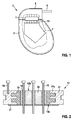
- Fig. 1 shows a pacemaker 1 with a pacemaker housing 3 and a header (header) 5, in the interior of which, in addition to other electronic components, a printed circuit board (PCB) 7 arranged and with its arranged in the header (not shown) line connection, an electrode line 9 is connected.
- a provided between the device housing 3 and header 5 implementation 11 includes a plurality of pins 13. The pins are inserted at one end through a corresponding hole in the circuit board and soldered to this soft.
- Fig. 2 shows, using the same reference numerals for functionally identical parts as in Fig. 1
- This comprises an outer annular plastic base body 15, which is produced as an injection-molded part, and inner disc-shaped ceramic base body 16, which is inserted into a through-flow flange 17 formed by metal-powder injection molding (MiM technology) 17 carries on its inner circumference a plurality of inwardly projecting into the material of the directly injected into the flange plastic base body 15 annular projections 17a.
- MIM technology metal-powder injection molding
- terminal pins 13 pierce the inner ceramic base body 16. They are integrally inserted into these each with a Weichlöttell 18 from a eutectic gold alloy solder. By using the low temperature solder joint, the soldering of the pins 13 into the inner ceramic body 16 is possible despite the fact that the surrounding outer plastic body 15 has a limited temperature resistance and would not withstand the temperatures required in a conventional brazing process.
- a ground pin 19 is inserted into the flange 17 (again soldered or simultaneously produced in the MiM method).
- a barrier layer 21 covering both base bodies 15, 16 on the passage surface 15a improves the diffusion resistance of the passage to gaseous or liquid components of the environment of use of the device.
- Fig. 3 represents in a very simplified schematic representation of another embodiment of a bushing 11 ', in which a ceramic insulator 16' connected both on its outer wall via a low-temperature braze 18.1 with a cold-formed bushing flange 17 'and in the interior of the body a low temperature braze joint 18.2 is provided for hermetically sealing a relatively heat sensitive terminal assembly 13 'constructed in LTCC technology.
- a low-temperature braze joint is understood here as one that can be generated in a free atmosphere, ie not in a vacuum or under inert gas.
- the application of a eutectic low-temperature solder not only allows the reduction of stress and an increase in general reliability, but above all, a novel design principle of implementation.
- Fig. 4 represents, again in a very schematic representation, another exemplary implementation 11 ", in which a ceramic insulator 16", which here surrounds a single pin 13 ", by means of a low-temperature braze 18" directly with a bent portion 3a of an implant housing 3 is soldered.
Landscapes
- Health & Medical Sciences (AREA)
- Engineering & Computer Science (AREA)
- Biomedical Technology (AREA)
- Nuclear Medicine, Radiotherapy & Molecular Imaging (AREA)
- Radiology & Medical Imaging (AREA)
- Life Sciences & Earth Sciences (AREA)
- Animal Behavior & Ethology (AREA)
- General Health & Medical Sciences (AREA)
- Public Health (AREA)
- Veterinary Medicine (AREA)
- Electrotherapy Devices (AREA)
Abstract
Durchführung eines implantierbaren medizinelektronischen Geräts, mit einem Gehäuse, einem Isolierkörper, einem den Isolierkörper umfassenden Durchführungs-Flansch und mindestens einem den Isolierkörper durchstoßenden Anschlusselement zum externen Anschluss eines elektrischen oder elektronischen Bauelements des Geräts, insbesondere mehreren Anschlusselementen, wobei zwischen dem Isolierkörper und dem Durchführungs-Flansch und/oder zwischen dem Isolierkörper und dem oder mindestens einem Anschlusselement und/oder zwischen dem Isolierkörper und dem Gehäuse eine Niedertemperatur-Hartlötverbindung oder Weichlötverbindung vorgesehen ist, die insbesondere bei einer Temperatur von 900°C oder weniger, bevorzugt weniger als 450°C, noch bevorzugter weniger als 400°C, gebildet ist.Implementation of an implantable medical electronic device, comprising a housing, an insulating body, a bushing through the insulating body and at least one connecting element piercing the insulating body for external connection of an electrical or electronic component of the device, in particular a plurality of connecting elements, between the insulating body and the bushing Flange and / or between the insulating body and the or at least one connecting element and / or between the insulating body and the housing, a low-temperature brazing or Weichlötverbindung is provided, in particular at a temperature of 900 ° C or less, preferably less than 450 ° C, more preferably less than 400 ° C is formed.
Description
Die Erfindung betrifft eine Durchführung eines implantierbaren medizinelektronischen Geräts, mit einem Isolierkörper, einem den Isolierkörper umfassenden Durchführungs-Flansch und mindestens einem den Isolierkörper durchstoßenden Anschlusselement zum externen Anschluss eines elektrischen oder elektronischen Bauelements des Geräts, insbesondere mehreren Anschlusselementen. Sie betrifft des Weiteren ein implantierbares medizinielektronisches Gerät, welches eine solche Durchführung enthält.The invention relates to an implementation of an implantable medical electronic device, comprising an insulating body, a comprehensive implementation of the insulating flange and at least one insulating body piercing connection element for external connection of an electrical or electronic component of the device, in particular a plurality of connection elements. It further relates to an implantable medical electronic device which includes such an implementation.
Derartige Geräte sind insbesondere als Herzschrittmacher oder implantierbare Kardioverter (speziell Defibrillatoren) seit langem in massenhaftem Einsatz. Es kann sich hierbei aber auch um eine weniger komplexe Vorrichtung, wie etwa eine Elektroden- oder Sensorleitung oder auch ein Cochlea-Implantat, handeln.Such devices are in particular as pacemakers or implantable cardioverter (especially defibrillators) for a long time in mass use. However, this may also be a less complex device, such as an electrode or sensor line or a cochlear implant act.
Die meisten praktisch bedeutsamen implantierbaren elektromedizinischen Geräte sind dazu vorgesehen, über geeignet platzierte Elektroden elektrische Impulse an reizbares Körpergewebe abzugeben. Um diese Funktion auszuführen, sind im Gehäuse des Gerätes elektronische/elektrische Funktionseinheiten zur Erzeugung der Impulse und zur geeigneten Steuerung der Impulserzeugung untergebracht, und außen am Gerät sind unmittelbar Elektroden oder Anschlüsse für mindestens eine Elektrodenleitung vorgesehen, in deren distalem Endabschnitt die Elektroden zur Impulsübertragung an das Gewebe angebracht sind. Die elektronischen/elektrischen Funktionseinheiten im Geräteinneren sind in einer Weise mit den äußeren Elektroden oder Elektrodenleitungsanschlüssen zu verbinden, die unter den speziellen Bedingungen des implantierten Zustandes eine absolut und dauerhaft verlässliche Funktion gewährleistet.Most practically important implantable electromedical devices are designed to deliver electrical impulses to irritable body tissue via appropriately placed electrodes. To carry out this function, electronic / electrical functional units for generating the pulses and for suitable control of pulse generation are accommodated in the housing of the device, and electrodes or connections for at least one electrode line are provided directly on the device, in the distal end section the electrodes for pulse transmission the tissues are attached. The electronic / electrical functional units inside the unit are to be connected in a manner with the outer electrodes or electrode lead terminals, which ensures an absolutely and permanently reliable function under the special conditions of the implanted state.
Bekannt sind insbesondere Durchführungen, deren Grund- und Isolationskörper im Wesentlichen aus Keramik oder Glas besteht, wobei auch mehrschichtige bzw. mehrteilige Aufbauten unter Einsatz von Metallen oder Metalloxiden entwickelt wurden und eingesetzt werden. Derartige bekannte Durchführungen erfüllen weitgehend die an sie gestellten Anforderungen. Jedoch müssen bei der Materialauswahl für die Komponenten Isolationskeramik/Glas, Metall- oder Glaslot, Metallpin und Metallflansch die thermischen Ausdehnungskoeffizienten berücksichtigt werden, um eine über die vorgesehene Lebensdauer ausreichende Dichtheit gewährleisten zu können.In particular, feedthroughs are known, whose base and insulating body consists essentially of ceramic or glass, with multi-layered or multi-part structures having been developed and used with the use of metals or metal oxides. Such known bushings largely meet the demands placed on them. However, in the selection of materials for the components insulating ceramic / glass, metal or glass solder, Metallpin and metal flange, the thermal expansion coefficients must be taken into account in order to ensure sufficient over the intended life tightness.
Beim konventionellen Design (Metallflansch - Lot - Isolationskeramik - Lot - Metallpin) kommt die Wirkung von nicht angepassten thermischen Ausdehnungskoeffizienten in erster Linie beim Abkühlen von Löttemperatur und Einschweißen der Durchführung ins Gehäuse zum Tragen. Resultieren können mechanische Zugspannungen, welche zur Materialtrennung und folglich zu etwaigen Leckagen der Durchführung führen können. Die bei konventionellen Durchführungen verwendeten keramischen und metallischen Komponenten sind durch den Lotwerkstoff miteinander verbunden; bei ungleichmäßiger Ausdehnung/Schrumpfung der Komponenten untereinander, einschließlich des Lotes, aufgrund von Aufheiz-/Abkühlvorgängen erzeugen die resultierenden relativen Längenänderungen entsprechende mechanische Spannungen.In the conventional design (metal flange - solder - insulation ceramic - solder - metal pin), the effect of unmatched thermal expansion coefficients comes first and foremost when cooling soldering temperature and welding the bushing into the housing. This can result in mechanical tensile stresses which can lead to material separation and consequently to possible leaks in the bushing. The ceramic and metallic components used in conventional bushings are interconnected by the solder material; with uneven expansion / contraction of the components, including the solder, due to heating / cooling processes, the resulting relative length changes produce corresponding mechanical stresses.
Aus der
Auch die
Aus der
Es ist auch bekannt, Hartlötverfahren zur stoffschlüssigen Verbindung etwa von Titan- und Nickel-Teilen unter Einsatz eutektischer Lote durchzuführen und hierdurch die mit Schweißverbindungen oder hochtemperatur-Lötverfahren einhergehenden thermischen Belastungen und daraus resultierenden Probleme zu verringern; vgl. N. Weyrich et. al. "Joining of Titanium and Nickel at Temperatures Below 450°C", Brazing, High Temperature Brazing and Diffusion Bonding, Löt 2013, p. 22. Bekannt ist auch der Einsatz niedrig schmelzender Au-Legierungs-Lote für das Einlöten von Filterkondensatoren in Durchführungen implantierbarer medizinischer Geräte; vgl. dazu
Der Erfindung liegt die Aufgabe zu Grunde, ein verbessertes implantierbares elektromedizinisches Gerät bereitzustellen, welches kostengünstig herstellbar und hochgradig zuverlässig ist.The invention is based on the object to provide an improved implantable electromedical device, which is inexpensive to produce and highly reliable.
Diese Aufgabe wird durch eine Durchführung mit den Merkmalen des Anspruchs 1 gelöst. Zweckmäßige Fortbildungen des Erfindungsgedankens sind Gegenstand der abhängigen Ansprüche. Des Weiteren wird ein entsprechendes implantierbares medizinelektronisches Gerät vorgeschlagen.This object is achieved by an implementation with the features of claim 1. Advantageous developments of the inventive concept are the subject of the dependent claims. Furthermore, a corresponding implantable medical electronic device is proposed.
Die Erfindung geht von der Überlegung aus, die für eine dauerhaft zuverlässige Funktion der Durchführung grundsätzlich kritischen Aufheiz- und Abkühlschritte mit deutlich geringeren Temperaturdifferenzen auszuführen und hierdurch die erwähnten Probleme zumindest wesentlich zu verringern. Hinzu tritt die Überlegung, dass verringerte maximale Prozesstemperaturen Potential für den Einsatz weniger temperaturbeständiger Materialien und generell größere Freiheitsgrade beim Entwurf der Durchführung bieten. Dies mündet in der Überlegung, zwischen dem Isolierkörper und dem Durchführungs-Flansch und/oder zwischen dem Isolierkörper und dem oder mindestens einem Anschlusselement und/oder zwischen dem Isolierkörper und dem Gehäuse eine Niedertemperatur-Hartlötverbindung oder Weichlötverbindung vorzusehen, die insbesondere bei einer Temperatur von 900°C oder weniger, bevorzugt weniger als 450°C, noch bevorzugter weniger als 400°C, gebildet ist.The invention is based on the idea that for a permanently reliable function of the implementation, in principle, perform critical heating and cooling steps with significantly lower temperature differences, thereby at least substantially reducing the aforementioned problems. Added to this is the consideration that reduced maximum process temperatures offer potential for the use of less temperature-resistant materials and generally greater degrees of freedom in the design of the bushing. This leads to the consideration between the insulating body and the bushing flange and / or between the insulating body and the or at least one connecting element and / or between the insulating body and the housing to provide a low-temperature braze or solder joint, in particular at a temperature of 900 ° C or less, preferably less than 450 ° C, more preferably less than 400 ° C is formed.
In einer Ausführung der Erfindung umfasst die Durchführung die Niedertemperatur-Hartlötverbindung mit einem unterhalb von 900°C, insbesondere unterhalb von 450°C und weiter insbesondere unterhalb von 400°C, schmelzenden eutektischen Gold-Legierungs-Lot gebildet ist, wie Au80Sn20, Au81Si19, Au94Sn6 oder Ähnlichem.In one embodiment of the invention, the feedthrough comprises the low-temperature brazing compound having a gold alloy eutectic solder melting below 900 ° C., in particular below 450 ° C. and more particularly below 400 ° C., such as Au 80 Sn 20, Au 81 Si 19, Au94Sn6 or similar.
In weiteren Ausführungen der Erfindung ist vorgesehen, dass die Durchführung die einen Bestandteil oder Bereich umfasst, der nur bis zu einer Temperatur von 1050°C, insbesondere nur bis 950°C oder weniger, begrenzt temperaturstabil ist.In further embodiments of the invention, it is provided that the bushing comprises a component or region which is only limited in temperature stability up to a temperature of 1050 ° C., in particular only up to 950 ° C. or less.
In einer Ausgestaltung dieser Ausführungen ist vorgesehen, dass der begrenzt temperaturstabile Bestandteil oder Bereich einen Metall/Keramik-Verbund aufweist.In one embodiment of these embodiments, it is provided that the limited temperature-stable component or region has a metal / ceramic composite.
In einer Variante dieser Ausführung weist der begrenzt temperaturstabile Bestandteil eine in LTCC-Technologie erstellte elektronische Anordnung, insbesondere Anordnung von Anschlusselementen, auf.In a variant of this embodiment, the component with limited temperature stability has an electronic arrangement produced in LTCC technology, in particular an arrangement of connection elements.
In weiteren Ausführungen weist der Isolierkörper mindestens eine Kunststoffkomponente auf. In einer Ausgestaltung ist vorgesehen, dass die Kunststoffkomponente ein Kunststoff Spritzgussteil oder eine Kunststoffbeschichtung eines Keramik- oder Glasteiles ist. Des Weiteren kann die Kunststoffkomponente eine Füllung mit nichtorganischen und nichtmetallischen Teilchen, insbesondere Keramik- und/oder Glasteilchen aufweisen.In further embodiments, the insulating body has at least one plastic component. In one embodiment, it is provided that the plastic component is a plastic injection molded part or a plastic coating of a ceramic or glass part. Furthermore, the plastic component may have a filling with non-organic and non-metallic particles, in particular ceramic and / or glass particles.
Vorteile und Zweckmäßigkeiten der Erfindung ergeben sich im Übrigen aus der Beschreibung von Ausführungsbeispielen anhand der Figuren. Von diesen zeigen:
- Fig. 1
- eine schematische, teilweise geschnittene Darstellung eines implantierbaren elektromedizinischen Geräts,
- Fig. 2
- eine schematische Querschnittsdarstellung (Teilansicht) eines Ausführungsbeispiels der Erfindung,
- Fig. 3
- eine schematische Querschnittsdarstellung (Teilansicht) eines weiteren Ausführungsbeispiels der Erfindung, und
- Fig. 4
- eine schematische Querschnittsdarstellung (Teilansicht) eines weiteren Ausführungsbeispiels der Erfindung.
- Fig. 1
- a schematic, partially sectioned view of an implantable electromedical device,
- Fig. 2
- a schematic cross-sectional view (partial view) of an embodiment of the invention,
- Fig. 3
- a schematic cross-sectional view (partial view) of another embodiment of the invention, and
- Fig. 4
- a schematic cross-sectional view (partial view) of another embodiment of the invention.
Mehrere Anschlussstifte 13 durchstoßen den inneren Keramik-Grundkörper 16. Sie sind in diesen jeweils mit einer Weichlötverbindung 18 aus einem eutektischen Gold-Legierungs-Lot stoffschlüssig eingefügt. Durch den Einsatz der niedertemperatur-Lötverbindung wird das Einlöten der Anschlussstifte 13 in den inneren Keramik-Grundkörper 16 ungeachtet dessen möglich, dass der umgebende äußere Kunststoff-Grundkörper 15 eine begrenzte Temperaturbeständigkeit hat und den bei einem herkömmlichen Hartlötverfahren benötigten Temperaturen nicht widerstehen würde.Several
In den Flansch 17 ist im Übrigen ein Massepin 19 eingefügt (wiederum eingelötet oder im MiM-Verfahren zugleich erzeugt). Eine beide Grundkörper 15, 16 auf der DurchführungOberfläche 15a bedeckende Barriereschicht 21 verbessert die Diffusionsfestigkeit der Durchführung gegenüber gasförmigen oder flüssigen Bestandteilen der Einsatzumgebung des Gerätes.Incidentally, a
Die Ausführung der Erfindung ist auch in einer Vielzahl von Abwandlungen der hier gezeigten Beispiele und weiter oben hervorgehobenen Aspekte der Erfindung möglich.The practice of the invention is also possible in a variety of variations of the examples shown herein and aspects of the invention highlighted above.
Claims (9)
wobei zwischen dem Isolierkörper und dem Durchführungs-Flansch und/oder zwischen dem Isolierkörper und dem oder mindestens einem Anschlusselement und/oder zwischen dem Isolierkörper und dem Gehäuse eine Niedertemperatur-Hartlötverbindung oder Weichlötverbindung (18; 18.1, 18.2) vorgesehen ist, die insbesondere bei einer Temperatur von 900°C oder weniger, bevorzugt weniger als 450°C, noch bevorzugter weniger als 400°C, gebildet ist.An implementation (11; 11 ') of an implantable medical electronic device (1) comprising a housing, an insulating body (15, 16; 16'), a bushing flange (17, 17 ') surrounding the insulating body and at least one connecting element piercing the insulating body (13, 13 ') for external connection of an electrical or electronic component of the device, in particular a plurality of connection elements,
wherein between the insulating body and the bushing flange and / or between the insulating body and the or at least one connecting element and / or between the insulating body and the housing, a low-temperature brazing or soldering connection (18, 18.1, 18.2) is provided, in particular in a Temperature of 900 ° C or less, preferably less than 450 ° C, more preferably less than 400 ° C, is formed.
Applications Claiming Priority (1)
| Application Number | Priority Date | Filing Date | Title |
|---|---|---|---|
| US201562135709P | 2015-03-20 | 2015-03-20 |
Publications (1)
| Publication Number | Publication Date |
|---|---|
| EP3069757A1 true EP3069757A1 (en) | 2016-09-21 |
Family
ID=55532114
Family Applications (1)
| Application Number | Title | Priority Date | Filing Date |
|---|---|---|---|
| EP16157065.0A Withdrawn EP3069757A1 (en) | 2015-03-20 | 2016-02-24 | Feedthrough of an implantable electronic medical device and implantable electronic medical device |
Country Status (2)
| Country | Link |
|---|---|
| US (1) | US20160271399A1 (en) |
| EP (1) | EP3069757A1 (en) |
Cited By (2)
| Publication number | Priority date | Publication date | Assignee | Title |
|---|---|---|---|---|
| DE102016107414A1 (en) * | 2016-04-21 | 2017-10-26 | Biotronik Se & Co. Kg | Implementation of an implantable medical electronic device and implantable medical electronic device |
| EP3461533A1 (en) * | 2017-09-29 | 2019-04-03 | BIOTRONIK SE & Co. KG | External casing part of an implantable medical electronic device |
Families Citing this family (1)
| Publication number | Priority date | Publication date | Assignee | Title |
|---|---|---|---|---|
| CN111355209A (en) * | 2020-03-10 | 2020-06-30 | 摩科斯新材料科技(苏州)有限公司 | Implantable ceramic feedthrough connector and method of making same |
Citations (8)
| Publication number | Priority date | Publication date | Assignee | Title |
|---|---|---|---|---|
| US5867361A (en) * | 1997-05-06 | 1999-02-02 | Medtronic Inc. | Adhesively-bonded capacitive filter feedthrough for implantable medical device |
| US7064270B2 (en) | 2003-10-29 | 2006-06-20 | Medtronic, Inc. | Implantable device feedthrough assembly |
| US20080119906A1 (en) * | 2006-11-17 | 2008-05-22 | Marcel Starke | Filter feedthrough for implants |
| US20110232962A1 (en) * | 2010-03-29 | 2011-09-29 | Biotronik Se & Co. Kg | Electrical Feedthrough, Method for the Production and Use Thereof |
| EP2388044A1 (en) | 2010-05-21 | 2011-11-23 | Dyconex AG | Electronic device or electric component |
| US20120212918A1 (en) * | 2011-02-22 | 2012-08-23 | Micro Systems Engineering Gmbh | Electrical Component Having an Electrical Connection Arrangement and Method for the Manufacture Thereof |
| US20130058003A1 (en) * | 2011-09-01 | 2013-03-07 | Medtronic, Inc. | Feedthrough assembly including a capacitive filter array |
| EP2232646B1 (en) | 2007-12-28 | 2014-05-21 | Emerson Electric Co. | Hermetic feed-through with hybrid seal structure |
Family Cites Families (2)
| Publication number | Priority date | Publication date | Assignee | Title |
|---|---|---|---|---|
| EP1811617A1 (en) * | 2006-01-18 | 2007-07-25 | JENOPTIK Laserdiode GmbH | Base for a vertical arrangement of laserdiode bars with a stop |
| DE102011119125B4 (en) * | 2011-11-23 | 2014-01-23 | Heraeus Precious Metals Gmbh & Co. Kg | Contacting arrangement with bushing and filter structure |
-
2016
- 2016-02-24 EP EP16157065.0A patent/EP3069757A1/en not_active Withdrawn
- 2016-02-26 US US15/054,496 patent/US20160271399A1/en not_active Abandoned
Patent Citations (10)
| Publication number | Priority date | Publication date | Assignee | Title |
|---|---|---|---|---|
| US5867361A (en) * | 1997-05-06 | 1999-02-02 | Medtronic Inc. | Adhesively-bonded capacitive filter feedthrough for implantable medical device |
| US5870272A (en) | 1997-05-06 | 1999-02-09 | Medtronic Inc. | Capacitive filter feedthrough for implantable medical device |
| US6031710A (en) | 1997-05-06 | 2000-02-29 | Medtronic, Inc. | Adhesively- and solder-bonded capacitive filter feedthrough for implantable medical devices |
| US7064270B2 (en) | 2003-10-29 | 2006-06-20 | Medtronic, Inc. | Implantable device feedthrough assembly |
| US20080119906A1 (en) * | 2006-11-17 | 2008-05-22 | Marcel Starke | Filter feedthrough for implants |
| EP2232646B1 (en) | 2007-12-28 | 2014-05-21 | Emerson Electric Co. | Hermetic feed-through with hybrid seal structure |
| US20110232962A1 (en) * | 2010-03-29 | 2011-09-29 | Biotronik Se & Co. Kg | Electrical Feedthrough, Method for the Production and Use Thereof |
| EP2388044A1 (en) | 2010-05-21 | 2011-11-23 | Dyconex AG | Electronic device or electric component |
| US20120212918A1 (en) * | 2011-02-22 | 2012-08-23 | Micro Systems Engineering Gmbh | Electrical Component Having an Electrical Connection Arrangement and Method for the Manufacture Thereof |
| US20130058003A1 (en) * | 2011-09-01 | 2013-03-07 | Medtronic, Inc. | Feedthrough assembly including a capacitive filter array |
Non-Patent Citations (2)
| Title |
|---|
| N. WEYRICH: "Joining of Titanium and Nickel at Temperatures Below 450°C", BRAZING, HIGH TEMPERATURE BRAZING AND DIFFUSION BONDING, 2013, pages 22 |
| WIKIPEDIA: "Löten", 23 January 2016 (2016-01-23), XP002759903, Retrieved from the Internet <URL:https://de.wikipedia.org/wiki/L%C3%B6ten> [retrieved on 20160706] * |
Cited By (4)
| Publication number | Priority date | Publication date | Assignee | Title |
|---|---|---|---|---|
| DE102016107414A1 (en) * | 2016-04-21 | 2017-10-26 | Biotronik Se & Co. Kg | Implementation of an implantable medical electronic device and implantable medical electronic device |
| EP3461533A1 (en) * | 2017-09-29 | 2019-04-03 | BIOTRONIK SE & Co. KG | External casing part of an implantable medical electronic device |
| EP3461534A1 (en) * | 2017-09-29 | 2019-04-03 | BIOTRONIK SE & Co. KG | External casing part of an implantable medical electronic device |
| US11129995B2 (en) | 2017-09-29 | 2021-09-28 | Biotronik Se & Co. Kg | Outer casing part of an implantable medical electronic device |
Also Published As
| Publication number | Publication date |
|---|---|
| US20160271399A1 (en) | 2016-09-22 |
Similar Documents
| Publication | Publication Date | Title |
|---|---|---|
| EP2371418B1 (en) | Electrical feedthrough for electromedical implants | |
| DE19819797C2 (en) | Feedthrough assembly for an implantable medical device | |
| EP1897588B1 (en) | Feedthrough connection | |
| EP2371417B1 (en) | Electrical feedthrough, method for the production and use thereof | |
| DE602004013217T2 (en) | Multi-pin feedthrough with a ground pin that goes through an insulator and is soldered directly to a ferrule | |
| DE102009008673B3 (en) | Punched feedthrough element with soldered contact pin | |
| DE102011009866B4 (en) | Directly applied electrical feedthrough | |
| EP3055095B1 (en) | Method for producing a metal-ceramic soldered connection | |
| US7839620B2 (en) | Filtered feedthrough assemblies for implantable devices and methods of manufacture | |
| EP2516321B1 (en) | Sensor comprising a preferably multilayered ceramic substrate and method for producing it | |
| EP1923099A1 (en) | Filter duct for implants | |
| EP2926864A1 (en) | Electric feedthrough for electromedical implants, electric contact element comprising such a feedthrough, and electromedical implant | |
| EP3069757A1 (en) | Feedthrough of an implantable electronic medical device and implantable electronic medical device | |
| EP2371419A2 (en) | Electrical feedthrough of a capacitor for medical implants and method for the production and use thereof | |
| EP3072553B1 (en) | Terminal pin and feedthrough | |
| DE60100794T2 (en) | HERMETIC GROUNDING PIN ARRANGEMENT | |
| DE2028838A1 (en) | ||
| EP3159039A1 (en) | Durchführung eines medizinelektronischen gerätes und medizinelektronisches gerät | |
| DE102019208035B4 (en) | Glass-to-metal bushing with a sleeve | |
| EP3332836B1 (en) | Feedthrough of an implantable medical electronic device | |
| EP3069760B1 (en) | Implantable electromedical device | |
| EP3181194A1 (en) | Feedthrough of a medical electronic device, method for producing same, and medical electronic device | |
| EP3195899A1 (en) | Feedthrough of a medical electronic device, method for producing same, and medical electronic device | |
| EP3200568B1 (en) | Battery bridge and method for activating an electronic device | |
| EP3069759A1 (en) | Implantable electromedical device with a feedthrough having a single piece polymeric base body |
Legal Events
| Date | Code | Title | Description |
|---|---|---|---|
| PUAI | Public reference made under article 153(3) epc to a published international application that has entered the european phase |
Free format text: ORIGINAL CODE: 0009012 |
|
| AK | Designated contracting states |
Kind code of ref document: A1 Designated state(s): AL AT BE BG CH CY CZ DE DK EE ES FI FR GB GR HR HU IE IS IT LI LT LU LV MC MK MT NL NO PL PT RO RS SE SI SK SM TR |
|
| AX | Request for extension of the european patent |
Extension state: BA ME |
|
| STAA | Information on the status of an ep patent application or granted ep patent |
Free format text: STATUS: THE APPLICATION IS DEEMED TO BE WITHDRAWN |
|
| 18D | Application deemed to be withdrawn |
Effective date: 20170322 |