EP3069757A1 - Realisation d'un appareil electronique medical implantable et appareil electronique medical implantable - Google Patents
Realisation d'un appareil electronique medical implantable et appareil electronique medical implantable Download PDFInfo
- Publication number
- EP3069757A1 EP3069757A1 EP16157065.0A EP16157065A EP3069757A1 EP 3069757 A1 EP3069757 A1 EP 3069757A1 EP 16157065 A EP16157065 A EP 16157065A EP 3069757 A1 EP3069757 A1 EP 3069757A1
- Authority
- EP
- European Patent Office
- Prior art keywords
- insulating body
- temperature
- component
- bushing
- plastic
- Prior art date
- Legal status (The legal status is an assumption and is not a legal conclusion. Google has not performed a legal analysis and makes no representation as to the accuracy of the status listed.)
- Withdrawn
Links
Images

Classifications
-
- A—HUMAN NECESSITIES
- A61—MEDICAL OR VETERINARY SCIENCE; HYGIENE
- A61N—ELECTROTHERAPY; MAGNETOTHERAPY; RADIATION THERAPY; ULTRASOUND THERAPY
- A61N1/00—Electrotherapy; Circuits therefor
- A61N1/18—Applying electric currents by contact electrodes
- A61N1/32—Applying electric currents by contact electrodes alternating or intermittent currents
- A61N1/36—Applying electric currents by contact electrodes alternating or intermittent currents for stimulation
- A61N1/372—Arrangements in connection with the implantation of stimulators
- A61N1/375—Constructional arrangements, e.g. casings
- A61N1/3752—Details of casing-lead connections
- A61N1/3754—Feedthroughs
Definitions
- the invention relates to an implementation of an implantable medical electronic device, comprising an insulating body, a comprehensive implementation of the insulating flange and at least one insulating body piercing connection element for external connection of an electrical or electronic component of the device, in particular a plurality of connection elements. It further relates to an implantable medical electronic device which includes such an implementation.
- Such devices are in particular as pacemakers or implantable cardioverter (especially defibrillators) for a long time in mass use.
- this may also be a less complex device, such as an electrode or sensor line or a cochlear implant act.
- Electrodes or connections for at least one electrode line are provided directly on the device, in the distal end section the electrodes for pulse transmission the tissues are attached.
- the electronic / electrical functional units inside the unit are to be connected in a manner with the outer electrodes or electrode lead terminals, which ensures an absolutely and permanently reliable function under the special conditions of the implanted state.
- feedthroughs are known, whose base and insulating body consists essentially of ceramic or glass, with multi-layered or multi-part structures having been developed and used with the use of metals or metal oxides.
- Such known bushings largely meet the demands placed on them.
- the thermal expansion coefficients must be taken into account in order to ensure sufficient over the intended life tightness.
- a hermetically sealed feedthrough structure comprising a multi-part base body in combination with sealing (non-structural) polymer layers is known.
- the preparation of such an implementation is highly complex in terms of the required work and test steps and also in terms of prefabrication, warehousing and feeding many different parts.
- US 7,064,270 B2 describes a multi-part lead-through which has been specially developed for an electrode lead and may comprise several plastic-made or plastic-coated components.
- brazing processes for the cohesive connection of, for example, titanium and nickel parts using eutectic solders and thereby to reduce the thermal stresses associated with welded joints or high-temperature brazing processes and resulting problems; see. N. Weyrich et. al. High Temperature Brazing and Diffusion Bonding, Brazing, 2013, p. 22. Also known is the use of low melting Au alloy solders for soldering filter capacitors in implementations of implantable medical devices; see. to US 5,870,272 or US 6,031,710 ,
- the invention is based on the object to provide an improved implantable electromedical device, which is inexpensive to produce and highly reliable.
- the invention is based on the idea that for a permanently reliable function of the implementation, in principle, perform critical heating and cooling steps with significantly lower temperature differences, thereby at least substantially reducing the aforementioned problems. Added to this is the consideration that reduced maximum process temperatures offer potential for the use of less temperature-resistant materials and generally greater degrees of freedom in the design of the bushing. This leads to the consideration between the insulating body and the bushing flange and / or between the insulating body and the or at least one connecting element and / or between the insulating body and the housing to provide a low-temperature braze or solder joint, in particular at a temperature of 900 ° C or less, preferably less than 450 ° C, more preferably less than 400 ° C is formed.
- the feedthrough comprises the low-temperature brazing compound having a gold alloy eutectic solder melting below 900 ° C., in particular below 450 ° C. and more particularly below 400 ° C., such as Au 80 Sn 20, Au 81 Si 19, Au94Sn6 or similar.
- the bushing comprises a component or region which is only limited in temperature stability up to a temperature of 1050 ° C., in particular only up to 950 ° C. or less.
- the limited temperature-stable component or region has a metal / ceramic composite.
- the component with limited temperature stability has an electronic arrangement produced in LTCC technology, in particular an arrangement of connection elements.
- the insulating body has at least one plastic component.
- the plastic component is a plastic injection molded part or a plastic coating of a ceramic or glass part.
- the plastic component may have a filling with non-organic and non-metallic particles, in particular ceramic and / or glass particles.
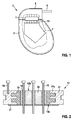
- Fig. 1 shows a pacemaker 1 with a pacemaker housing 3 and a header (header) 5, in the interior of which, in addition to other electronic components, a printed circuit board (PCB) 7 arranged and with its arranged in the header (not shown) line connection, an electrode line 9 is connected.
- a provided between the device housing 3 and header 5 implementation 11 includes a plurality of pins 13. The pins are inserted at one end through a corresponding hole in the circuit board and soldered to this soft.
- Fig. 2 shows, using the same reference numerals for functionally identical parts as in Fig. 1
- This comprises an outer annular plastic base body 15, which is produced as an injection-molded part, and inner disc-shaped ceramic base body 16, which is inserted into a through-flow flange 17 formed by metal-powder injection molding (MiM technology) 17 carries on its inner circumference a plurality of inwardly projecting into the material of the directly injected into the flange plastic base body 15 annular projections 17a.
- MIM technology metal-powder injection molding
- terminal pins 13 pierce the inner ceramic base body 16. They are integrally inserted into these each with a Weichlöttell 18 from a eutectic gold alloy solder. By using the low temperature solder joint, the soldering of the pins 13 into the inner ceramic body 16 is possible despite the fact that the surrounding outer plastic body 15 has a limited temperature resistance and would not withstand the temperatures required in a conventional brazing process.
- a ground pin 19 is inserted into the flange 17 (again soldered or simultaneously produced in the MiM method).
- a barrier layer 21 covering both base bodies 15, 16 on the passage surface 15a improves the diffusion resistance of the passage to gaseous or liquid components of the environment of use of the device.
- Fig. 3 represents in a very simplified schematic representation of another embodiment of a bushing 11 ', in which a ceramic insulator 16' connected both on its outer wall via a low-temperature braze 18.1 with a cold-formed bushing flange 17 'and in the interior of the body a low temperature braze joint 18.2 is provided for hermetically sealing a relatively heat sensitive terminal assembly 13 'constructed in LTCC technology.
- a low-temperature braze joint is understood here as one that can be generated in a free atmosphere, ie not in a vacuum or under inert gas.
- the application of a eutectic low-temperature solder not only allows the reduction of stress and an increase in general reliability, but above all, a novel design principle of implementation.
- Fig. 4 represents, again in a very schematic representation, another exemplary implementation 11 ", in which a ceramic insulator 16", which here surrounds a single pin 13 ", by means of a low-temperature braze 18" directly with a bent portion 3a of an implant housing 3 is soldered.
Applications Claiming Priority (1)
| Application Number | Priority Date | Filing Date | Title |
|---|---|---|---|
| US201562135709P | 2015-03-20 | 2015-03-20 |
Publications (1)
| Publication Number | Publication Date |
|---|---|
| EP3069757A1 true EP3069757A1 (fr) | 2016-09-21 |
Family
ID=55532114
Family Applications (1)
| Application Number | Title | Priority Date | Filing Date |
|---|---|---|---|
| EP16157065.0A Withdrawn EP3069757A1 (fr) | 2015-03-20 | 2016-02-24 | Realisation d'un appareil electronique medical implantable et appareil electronique medical implantable |
Country Status (2)
| Country | Link |
|---|---|
| US (1) | US20160271399A1 (fr) |
| EP (1) | EP3069757A1 (fr) |
Cited By (2)
| Publication number | Priority date | Publication date | Assignee | Title |
|---|---|---|---|---|
| DE102016107414A1 (de) * | 2016-04-21 | 2017-10-26 | Biotronik Se & Co. Kg | Durchführung eines implantierbaren medizinelektronischen Gerätes und implantierbares medizinelektronisches Gerät |
| EP3461534A1 (fr) * | 2017-09-29 | 2019-04-03 | BIOTRONIK SE & Co. KG | Partie du boitier extérieur d'un appareil médical électronique implantable |
Families Citing this family (1)
| Publication number | Priority date | Publication date | Assignee | Title |
|---|---|---|---|---|
| CN111355209A (zh) * | 2020-03-10 | 2020-06-30 | 摩科斯新材料科技(苏州)有限公司 | 植入式陶瓷馈通连接器及其制造方法 |
Citations (8)
| Publication number | Priority date | Publication date | Assignee | Title |
|---|---|---|---|---|
| US5867361A (en) * | 1997-05-06 | 1999-02-02 | Medtronic Inc. | Adhesively-bonded capacitive filter feedthrough for implantable medical device |
| US7064270B2 (en) | 2003-10-29 | 2006-06-20 | Medtronic, Inc. | Implantable device feedthrough assembly |
| US20080119906A1 (en) * | 2006-11-17 | 2008-05-22 | Marcel Starke | Filter feedthrough for implants |
| US20110232962A1 (en) * | 2010-03-29 | 2011-09-29 | Biotronik Se & Co. Kg | Electrical Feedthrough, Method for the Production and Use Thereof |
| EP2388044A1 (fr) | 2010-05-21 | 2011-11-23 | Dyconex AG | Appareil électronique ou composant électrique |
| US20120212918A1 (en) * | 2011-02-22 | 2012-08-23 | Micro Systems Engineering Gmbh | Electrical Component Having an Electrical Connection Arrangement and Method for the Manufacture Thereof |
| US20130058003A1 (en) * | 2011-09-01 | 2013-03-07 | Medtronic, Inc. | Feedthrough assembly including a capacitive filter array |
| EP2232646B1 (fr) | 2007-12-28 | 2014-05-21 | Emerson Electric Co. | Trou d'interconnexion hermétique avec une structure d'enrobage hybride |
Family Cites Families (2)
| Publication number | Priority date | Publication date | Assignee | Title |
|---|---|---|---|---|
| EP1811617A1 (fr) * | 2006-01-18 | 2007-07-25 | JENOPTIK Laserdiode GmbH | Base pour un arrangement vertical des barres de diode laser avec un arrêt |
| DE102011119125B4 (de) * | 2011-11-23 | 2014-01-23 | Heraeus Precious Metals Gmbh & Co. Kg | Kontaktierungsanordnung mit Durchführung und Filterstruktur |
-
2016
- 2016-02-24 EP EP16157065.0A patent/EP3069757A1/fr not_active Withdrawn
- 2016-02-26 US US15/054,496 patent/US20160271399A1/en not_active Abandoned
Patent Citations (10)
| Publication number | Priority date | Publication date | Assignee | Title |
|---|---|---|---|---|
| US5867361A (en) * | 1997-05-06 | 1999-02-02 | Medtronic Inc. | Adhesively-bonded capacitive filter feedthrough for implantable medical device |
| US5870272A (en) | 1997-05-06 | 1999-02-09 | Medtronic Inc. | Capacitive filter feedthrough for implantable medical device |
| US6031710A (en) | 1997-05-06 | 2000-02-29 | Medtronic, Inc. | Adhesively- and solder-bonded capacitive filter feedthrough for implantable medical devices |
| US7064270B2 (en) | 2003-10-29 | 2006-06-20 | Medtronic, Inc. | Implantable device feedthrough assembly |
| US20080119906A1 (en) * | 2006-11-17 | 2008-05-22 | Marcel Starke | Filter feedthrough for implants |
| EP2232646B1 (fr) | 2007-12-28 | 2014-05-21 | Emerson Electric Co. | Trou d'interconnexion hermétique avec une structure d'enrobage hybride |
| US20110232962A1 (en) * | 2010-03-29 | 2011-09-29 | Biotronik Se & Co. Kg | Electrical Feedthrough, Method for the Production and Use Thereof |
| EP2388044A1 (fr) | 2010-05-21 | 2011-11-23 | Dyconex AG | Appareil électronique ou composant électrique |
| US20120212918A1 (en) * | 2011-02-22 | 2012-08-23 | Micro Systems Engineering Gmbh | Electrical Component Having an Electrical Connection Arrangement and Method for the Manufacture Thereof |
| US20130058003A1 (en) * | 2011-09-01 | 2013-03-07 | Medtronic, Inc. | Feedthrough assembly including a capacitive filter array |
Non-Patent Citations (2)
| Title |
|---|
| N. WEYRICH: "Joining of Titanium and Nickel at Temperatures Below 450°C", BRAZING, HIGH TEMPERATURE BRAZING AND DIFFUSION BONDING, 2013, pages 22 |
| WIKIPEDIA: "Löten", 23 January 2016 (2016-01-23), XP002759903, Retrieved from the Internet <URL:https://de.wikipedia.org/wiki/L%C3%B6ten> [retrieved on 20160706] * |
Cited By (4)
| Publication number | Priority date | Publication date | Assignee | Title |
|---|---|---|---|---|
| DE102016107414A1 (de) * | 2016-04-21 | 2017-10-26 | Biotronik Se & Co. Kg | Durchführung eines implantierbaren medizinelektronischen Gerätes und implantierbares medizinelektronisches Gerät |
| EP3461534A1 (fr) * | 2017-09-29 | 2019-04-03 | BIOTRONIK SE & Co. KG | Partie du boitier extérieur d'un appareil médical électronique implantable |
| EP3461533A1 (fr) * | 2017-09-29 | 2019-04-03 | BIOTRONIK SE & Co. KG | Partie du boitier extérieur d'un appareil médical électronique implantable |
| US11129995B2 (en) | 2017-09-29 | 2021-09-28 | Biotronik Se & Co. Kg | Outer casing part of an implantable medical electronic device |
Also Published As
| Publication number | Publication date |
|---|---|
| US20160271399A1 (en) | 2016-09-22 |
Similar Documents
| Publication | Publication Date | Title |
|---|---|---|
| EP2371418B1 (fr) | Conduite électrique pour implants électromédicaux | |
| DE19819797C2 (de) | Durchführungsbaugruppe für eine implantierbare medizinische Vorrichtung | |
| EP1897588B1 (fr) | Conducteurs tranversants | |
| EP2371417B1 (fr) | Conduite électrique, procédé de fabrication et d'utilisation de celle-ci | |
| DE602004013217T2 (de) | Mehrstift-durchführung mit einem Erdungsstift , der einen Isolator durchgeht und mit einem Ferrule direkt gelötet ist | |
| DE102009008673B3 (de) | Gestanztes Durchführungselement mit eingelötetem Kontaktstift | |
| EP3055095B1 (fr) | Procédé de production d'une liaison par brasage métal-céramique | |
| US7839620B2 (en) | Filtered feedthrough assemblies for implantable devices and methods of manufacture | |
| EP2516321B1 (fr) | Capteur comportant un substrat céramique de préférence multicouche et procédé de fabrication correspondant | |
| EP0269007A1 (fr) | Assemblage céramique-métal, en particulier pour stimulateur cardiaque ou neurologique, et procédé de fabrication | |
| EP1923099A1 (fr) | Passage de filtre pour implants | |
| EP2926864A1 (fr) | Passage électrique pour implants électromédicaux, élément de contact électrique doté d'un tel passage et implant électromédical | |
| EP3069757A1 (fr) | Realisation d'un appareil electronique medical implantable et appareil electronique medical implantable | |
| EP3072553B1 (fr) | Broche de raccordement et traversée | |
| DE60100794T2 (de) | Hermetische erdungsstiftanordnung | |
| DE2028838A1 (fr) | ||
| EP3159039A1 (fr) | Durchführung eines medizinelektronischen gerätes und medizinelektronisches gerät | |
| DE102019208035B4 (de) | Glas-Metall-Durchführung mit einer Hülse | |
| EP3181194A1 (fr) | Réalisation d'un appareil médical électronique, son procédé de production et appareil médical électronique | |
| EP3332836B1 (fr) | Traversée d'un appareil médical électronique implantable | |
| EP3069760B1 (fr) | Dispositif electromedical implantable | |
| EP3195899A1 (fr) | Traversée d'un appareil médical électronique, son procédé de fabrication et appareil médical électronique | |
| EP3200568B1 (fr) | Élément de liaison pour batterie et procédé d'activation d'un dispositif électronique | |
| EP3069759A1 (fr) | Appareil electro-medical implantable avec une traversée ayant un corps de base monobloc en polymère | |
| DE102017209278A1 (de) | Elektronische Komponente und Verfahren zur Herstellung einer elektronischen Komponente |
Legal Events
| Date | Code | Title | Description |
|---|---|---|---|
| PUAI | Public reference made under article 153(3) epc to a published international application that has entered the european phase |
Free format text: ORIGINAL CODE: 0009012 |
|
| AK | Designated contracting states |
Kind code of ref document: A1 Designated state(s): AL AT BE BG CH CY CZ DE DK EE ES FI FR GB GR HR HU IE IS IT LI LT LU LV MC MK MT NL NO PL PT RO RS SE SI SK SM TR |
|
| AX | Request for extension of the european patent |
Extension state: BA ME |
|
| STAA | Information on the status of an ep patent application or granted ep patent |
Free format text: STATUS: THE APPLICATION IS DEEMED TO BE WITHDRAWN |
|
| 18D | Application deemed to be withdrawn |
Effective date: 20170322 |