EP2623865A1 - Brûleur à gaz, procédé de fonctionnement associé et système de brûleur à gaz multiples - Google Patents
Brûleur à gaz, procédé de fonctionnement associé et système de brûleur à gaz multiples Download PDFInfo
- Publication number
- EP2623865A1 EP2623865A1 EP12153790.6A EP12153790A EP2623865A1 EP 2623865 A1 EP2623865 A1 EP 2623865A1 EP 12153790 A EP12153790 A EP 12153790A EP 2623865 A1 EP2623865 A1 EP 2623865A1
- Authority
- EP
- European Patent Office
- Prior art keywords
- gas
- burner
- air
- fan
- backflow
- Prior art date
- Legal status (The legal status is an assumption and is not a legal conclusion. Google has not performed a legal analysis and makes no representation as to the accuracy of the status listed.)
- Granted
Links
- 238000000034 method Methods 0.000 title claims abstract description 15
- 239000000203 mixture Substances 0.000 claims abstract description 26
- 238000002485 combustion reaction Methods 0.000 description 4
- 230000001419 dependent effect Effects 0.000 description 1
- 238000001514 detection method Methods 0.000 description 1
- 238000011161 development Methods 0.000 description 1
- 230000018109 developmental process Effects 0.000 description 1
- 230000001105 regulatory effect Effects 0.000 description 1
Images

Classifications
-
- F—MECHANICAL ENGINEERING; LIGHTING; HEATING; WEAPONS; BLASTING
- F23—COMBUSTION APPARATUS; COMBUSTION PROCESSES
- F23N—REGULATING OR CONTROLLING COMBUSTION
- F23N5/00—Systems for controlling combustion
- F23N5/24—Preventing development of abnormal or undesired conditions, i.e. safety arrangements
- F23N5/242—Preventing development of abnormal or undesired conditions, i.e. safety arrangements using electronic means
-
- F—MECHANICAL ENGINEERING; LIGHTING; HEATING; WEAPONS; BLASTING
- F23—COMBUSTION APPARATUS; COMBUSTION PROCESSES
- F23N—REGULATING OR CONTROLLING COMBUSTION
- F23N5/00—Systems for controlling combustion
- F23N5/18—Systems for controlling combustion using detectors sensitive to rate of flow of air or fuel
- F23N5/187—Systems for controlling combustion using detectors sensitive to rate of flow of air or fuel using electrical or electromechanical means
-
- F—MECHANICAL ENGINEERING; LIGHTING; HEATING; WEAPONS; BLASTING
- F23—COMBUSTION APPARATUS; COMBUSTION PROCESSES
- F23N—REGULATING OR CONTROLLING COMBUSTION
- F23N2227/00—Ignition or checking
- F23N2227/02—Starting or ignition cycles
-
- F—MECHANICAL ENGINEERING; LIGHTING; HEATING; WEAPONS; BLASTING
- F23—COMBUSTION APPARATUS; COMBUSTION PROCESSES
- F23N—REGULATING OR CONTROLLING COMBUSTION
- F23N2237/00—Controlling
- F23N2237/02—Controlling two or more burners
-
- F—MECHANICAL ENGINEERING; LIGHTING; HEATING; WEAPONS; BLASTING
- F23—COMBUSTION APPARATUS; COMBUSTION PROCESSES
- F23N—REGULATING OR CONTROLLING COMBUSTION
- F23N2237/00—Controlling
- F23N2237/08—Controlling two or more different types of fuel simultaneously
Definitions
- the present patent application relates to a method for operating a gas burner. Further on, the present patent application relates to a gas burner and a multi gas burner system.
- EP 1 084 369 B1 and EP 1 179 159 B1 each disclose a method for operating a gas burner.
- a gas/air mixture having a defined mixing ratio of gas and air is provided to a burner chamber of the gas burner.
- the gas/air mixture is provided by mixing an air flow provided by an air duct with a gas flow provided by a gas duct using a mixing device.
- the quantity of the air flow is adjusted by a fan.
- the defined mixing ratio of the gas/air mixture is controlled by a controller on basis of a signal provided by an electrical or electronic sensor.
- the electrical or electronic sensor is coupled to the gas duct and to the air duct.
- the electrical or electronic sensor is coupled to the gas duct and to a reference point.
- the electrical or electronic sensor is especially designed as a flow-meter.
- An actual value corresponding to a pressure ratio between the gas pressure in the gas duct and the air pressure in the air duct or corresponding to a pressure ratio between the gas pressure in the gas duct and the air pressure at the reference point is provided by the electrical or electronic sensor, wherein this actual value is compared with a nominal value.
- a control variable for a gas valve assigned to the gas duct is generated on basis of the control deviation between the actual value and nominal value, wherein the gas valve is adjusted on basis of this control variable in order to provide the defined mixing ratio of gas and air in the gas/air mixture.
- gas burners known from prior art are fitted with mechanical devices like flapper valves.
- the prior art document US 2010/0330512 A1 discloses a multi gas burner system having several gas burners connected to a common exhaust pipe, wherein each gas burner comprises a damper to prevent backflow of exhaust gas.
- Such mechanical devices like flapper valves or dampers are costly and not always reliable.
- the method for operating a gas burner is defined in the claim 1. During burner-off phases the actual value provided by the electrical or electronic sensor is used to determine backflow.
- the method of the present patent application allows the determination of backflow of air or exhaust gas during burner-off phases on basis of a signal provided by the electrical or electronic sensor, whereby this electrical or electronic sensor is used during burner-on phases to control the mixing ratio of gas and air in the gas/air mixture. No, additional devices are need to determine backflow.
- the fan is turned on in such a way that the fan compensates the backflow resulting in a zero flow.
- This way of operating the fan during burner-off phases is very efficient.
- An electrical power consumption of the fan at low fan speeds is very low. Further on, this way of operating the fan keeps noises caused by the fan at a minimum.
- the gas burner is defined in the claim 7 and the multi gas burner system is defined in the claim 11.
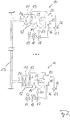
- Figure 1 shows a schematic view of a gas burner 10.
- the gas burner comprises a burner chamber 11 in which combustion of a gas/air mixture takes place during burner-on phases of the gas burner 10.
- the combustion of the gas/air mixture results into flames 12 monitored by e.g. an ionization sensor 13.
- the gas/air mixture is provided to the burner chamber 11 of the gas burner 10 by mixing an air flow with a gas flow.
- a fan 14 sucks in air flowing through an air duct 15 and gas flowing though a gas duct 16.
- a gas valve 17 for adjusting the gas flow through the gas duct 16 and safety valves 18, 19 are assigned to the gas duct 16.
- the gas/air mixture having a defined mixing ratio of gas and air is provided to the burner chamber 11 of the gas burner 10.
- the gas/air mixture is provided by mixing the air flow provided by an air duct 15 with a gas flow provided by a gas duct 16.
- the air flow and the gas flow become preferably mixed by a mixing device.
- a mixing device can be designed as a Venturi nozzle (not shown).
- the quantity of the air flow and thereby the quantity of the gas/air mixture flow is adjusted by the fan 14, namely by the speed of the fan 14.
- the fan speed can be adjusted by an actuator 22 of the fan 14.
- the defined mixing ratio of the gas/air mixture is controlled by a controller 20 on basis of a signal provided by an electrical or electronic sensor 23.
- the electrical or electronic sensor 23 is coupled to the gas duct 16 and to a reference point 26.
- the electrical or electronic sensor 23 is designed as a flow-meter.
- An actual value corresponding to a pressure ratio between the gas pressure in the gas duct 16 and the air pressure air pressure at the reference point 26 is provided by the electrical or electronic sensor 23.
- This actual value is compared by the controller 20 with a nominal value stored in the controller 20.
- the controller 20 generates a control variable for the gas valve 17, namely for an actuator 21 of the gas valve 17, on basis of the control deviation between the actual value provided by the electrical or electronic sensor 23 and the nominal value stored in the controller 20.
- the gas valve position of the gas valve 17 is adjusted by the actuator 21 of the same on basis of this control variable in order to provide the defined mixing ratio of gas and air in the gas/air mixture.
- Exhaust gas resulting form the combustion of the gas/air mixture within the burner chamber 11 during burner-on phases of the gas burner 10 is leaving the burner chamber 11 through an exhaust outlet 24 of the burner chamber 11.
- the exhaust gas flows than into an exhaust pipe 25.
- the actual value provided by the electrical or electronic sensor 23 is used to determine backflow, namely backflow of exhaust gas or air.
- the electrical or electronic sensor 23 provides the actual value to the controller 20 and the controller 20 determines from this actual value and a nominal value valid for burner-off phases the presence of backflow of exhaust gas or air.
- the fan 14 of the gas burner 10 When backflow is determined during burner-off phases, the fan 14 of the gas burner 10 is turned on.
- the controller 20 generates a signal for the actuator 22 of the fan 14 in order to turn the same on during burner-off phases when back flow was detected.
- the fan 14 is turned on in such a way that the fan 14 provides a flow through the burner chamber 11 opposite to the direction of the backflow.
- the fan 14 is turned on in such a way that the fan 14 merely compensates the backflow resulting in a zero flow through the burner chamber 11.
- This way of operating the fan 14 during burner-off phases is energy efficient. An electrical power consumption of the fan at a low fan speed is very low. Further on, this way of operating the fan 14 keeps noises caused by the fan 14 at a minimum.
- Figure 2 shows a multi gas burner system having at least two gas burners 10.
- the gas burners 10 are connected to a common exhaust pipe 25.
- At least one of the gas burners 10, preferably all gas burners 10, of the multi gas burner system comprise the functionality as described above.
- the detection of backflow is particularly of advantage in such a multi gas burner system. In such multi gas burner system the risk of backflow of exhaust gas is significantly higher than in a single gas burner application. By turning on the fan of the gas burner 10 for which backflow has been detected, further backflow into the same can be avoided.
- the present patent application avoids the use of mechanical devices like flapper valves or dampers to stop backflow.
Landscapes
- Engineering & Computer Science (AREA)
- Chemical & Material Sciences (AREA)
- Combustion & Propulsion (AREA)
- Mechanical Engineering (AREA)
- General Engineering & Computer Science (AREA)
- Regulation And Control Of Combustion (AREA)
Priority Applications (1)
| Application Number | Priority Date | Filing Date | Title |
|---|---|---|---|
| EP12153790.6A EP2623865B1 (fr) | 2012-02-03 | 2012-02-03 | Brûleur à gaz, procédé de fonctionnement associé et système de brûleur à gaz multiples |
Applications Claiming Priority (1)
| Application Number | Priority Date | Filing Date | Title |
|---|---|---|---|
| EP12153790.6A EP2623865B1 (fr) | 2012-02-03 | 2012-02-03 | Brûleur à gaz, procédé de fonctionnement associé et système de brûleur à gaz multiples |
Publications (2)
| Publication Number | Publication Date |
|---|---|
| EP2623865A1 true EP2623865A1 (fr) | 2013-08-07 |
| EP2623865B1 EP2623865B1 (fr) | 2020-04-08 |
Family
ID=45655373
Family Applications (1)
| Application Number | Title | Priority Date | Filing Date |
|---|---|---|---|
| EP12153790.6A Active EP2623865B1 (fr) | 2012-02-03 | 2012-02-03 | Brûleur à gaz, procédé de fonctionnement associé et système de brûleur à gaz multiples |
Country Status (1)
| Country | Link |
|---|---|
| EP (1) | EP2623865B1 (fr) |
Cited By (3)
| Publication number | Priority date | Publication date | Assignee | Title |
|---|---|---|---|---|
| EP2966354A1 (fr) * | 2014-07-08 | 2016-01-13 | Honeywell Technologies Sarl | Procédé et contrôleur de fonctionnement d'un brûleur à gaz |
| JP2020094764A (ja) * | 2018-12-13 | 2020-06-18 | 大阪瓦斯株式会社 | ファンを有する熱源機、当該熱源機を含む排気システム及び排気処理方法 |
| EP3763997A1 (fr) * | 2019-07-11 | 2021-01-13 | Viessmann Werke GmbH & Co. KG | Procédé de fonctionnement d'un brûleur à ventilateur |
Citations (5)
| Publication number | Priority date | Publication date | Assignee | Title |
|---|---|---|---|---|
| EP1084369A1 (fr) * | 1998-06-02 | 2001-03-21 | Honeywell B.V. | Systeme de regulation pour bruleur a gaz |
| EP1179159B1 (fr) | 1999-05-14 | 2004-11-24 | Honeywell B.V. | Dispositif de regulation pour bruleur de gaz |
| DE102005034758B3 (de) * | 2005-07-21 | 2006-08-10 | Honeywell Technologies S.A.R.L. | Verfahren zum Betreiben eines Gasbrenners |
| US20100330512A1 (en) | 2008-05-20 | 2010-12-30 | Kim Si-Hwan | Multi-boiler and control method thereof for preventing back flow of exhaust gas |
| AT510002A4 (de) * | 2010-12-20 | 2012-01-15 | Vaillant Group Austria Gmbh | Verfahren zur regelung eines gas-/luftgemisches |
-
2012
- 2012-02-03 EP EP12153790.6A patent/EP2623865B1/fr active Active
Patent Citations (6)
| Publication number | Priority date | Publication date | Assignee | Title |
|---|---|---|---|---|
| EP1084369A1 (fr) * | 1998-06-02 | 2001-03-21 | Honeywell B.V. | Systeme de regulation pour bruleur a gaz |
| EP1084369B1 (fr) | 1998-06-02 | 2003-01-15 | Honeywell B.V. | Systeme de regulation pour bruleur a gaz |
| EP1179159B1 (fr) | 1999-05-14 | 2004-11-24 | Honeywell B.V. | Dispositif de regulation pour bruleur de gaz |
| DE102005034758B3 (de) * | 2005-07-21 | 2006-08-10 | Honeywell Technologies S.A.R.L. | Verfahren zum Betreiben eines Gasbrenners |
| US20100330512A1 (en) | 2008-05-20 | 2010-12-30 | Kim Si-Hwan | Multi-boiler and control method thereof for preventing back flow of exhaust gas |
| AT510002A4 (de) * | 2010-12-20 | 2012-01-15 | Vaillant Group Austria Gmbh | Verfahren zur regelung eines gas-/luftgemisches |
Cited By (3)
| Publication number | Priority date | Publication date | Assignee | Title |
|---|---|---|---|---|
| EP2966354A1 (fr) * | 2014-07-08 | 2016-01-13 | Honeywell Technologies Sarl | Procédé et contrôleur de fonctionnement d'un brûleur à gaz |
| JP2020094764A (ja) * | 2018-12-13 | 2020-06-18 | 大阪瓦斯株式会社 | ファンを有する熱源機、当該熱源機を含む排気システム及び排気処理方法 |
| EP3763997A1 (fr) * | 2019-07-11 | 2021-01-13 | Viessmann Werke GmbH & Co. KG | Procédé de fonctionnement d'un brûleur à ventilateur |
Also Published As
| Publication number | Publication date |
|---|---|
| EP2623865B1 (fr) | 2020-04-08 |
Similar Documents
| Publication | Publication Date | Title |
|---|---|---|
| US8635997B2 (en) | Systems and methods for controlling gas pressure to gas-fired appliances | |
| EP2667097B1 (fr) | Procédé de fonctionnement d'un brûleur à gaz | |
| EP2141335B1 (fr) | Système de chauffage d'air d'admission pour moteur à turbine à gaz | |
| EP3228936B1 (fr) | Procédé de fonctionnement d'un appareil à brûleur à gaz | |
| EP2966354B1 (fr) | Procédé de fonctionnement d'un brûleur à gaz | |
| US9134026B2 (en) | Method for operating a gas burner | |
| EP2660515A2 (fr) | Dispositif de combustion de prémélange de brûleur à gaz | |
| US20090197212A1 (en) | Premix Burner Control System and Method | |
| US8591221B2 (en) | Combustion blower control for modulating furnace | |
| WO2007126980A3 (fr) | Intégration de combustion par oxy-carburant et air-carburant | |
| JP2013076479A (ja) | ボイラ | |
| EP2623865B1 (fr) | Brûleur à gaz, procédé de fonctionnement associé et système de brûleur à gaz multiples | |
| EP2685169B1 (fr) | Procédé de fonctionnement d'un brûleur à gaz | |
| EP2631541B1 (fr) | Procédé de fonctionnement d'un brûleur à gaz | |
| EP2685168B1 (fr) | Procédé de fonctionnement d'un brûleur à gaz | |
| EP2728256B1 (fr) | Modulation de système de brûleur | |
| CN105658934B (zh) | 控制燃气轮机设备的排放物的方法和燃气轮机设备 | |
| EP2685167B1 (fr) | Procédé de fonctionnement d'un brûleur à gaz | |
| US20230090905A1 (en) | Flame monitoring device for a gas burner appliance and gas burner appliance | |
| JP4873530B2 (ja) | 燃焼装置 | |
| JP2015210042A (ja) | ボイラ | |
| JP2014005971A (ja) | ボイラ | |
| CN205807421U (zh) | 炉用燃烧器脉冲控制系统 | |
| CN108351099B (zh) | 减少具有密封的强制通风燃烧室的燃气锅炉的有害气体排放物的方法和相应的锅炉 | |
| WO2015146426A1 (fr) | Chaudière |
Legal Events
| Date | Code | Title | Description |
|---|---|---|---|
| PUAI | Public reference made under article 153(3) epc to a published international application that has entered the european phase |
Free format text: ORIGINAL CODE: 0009012 |
|
| AK | Designated contracting states |
Kind code of ref document: A1 Designated state(s): AL AT BE BG CH CY CZ DE DK EE ES FI FR GB GR HR HU IE IS IT LI LT LU LV MC MK MT NL NO PL PT RO RS SE SI SK SM TR |
|
| AX | Request for extension of the european patent |
Extension state: BA ME |
|
| 17P | Request for examination filed |
Effective date: 20140130 |
|
| RBV | Designated contracting states (corrected) |
Designated state(s): AL AT BE BG CH CY CZ DE DK EE ES FI FR GB GR HR HU IE IS IT LI LT LU LV MC MK MT NL NO PL PT RO RS SE SI SK SM TR |
|
| REG | Reference to a national code |
Ref country code: DE Ref legal event code: R079 Ref document number: 602012069043 Country of ref document: DE Free format text: PREVIOUS MAIN CLASS: F23N0005240000 Ipc: F23N0005180000 |
|
| GRAP | Despatch of communication of intention to grant a patent |
Free format text: ORIGINAL CODE: EPIDOSNIGR1 |
|
| STAA | Information on the status of an ep patent application or granted ep patent |
Free format text: STATUS: GRANT OF PATENT IS INTENDED |
|
| RIC1 | Information provided on ipc code assigned before grant |
Ipc: F23N 5/24 20060101ALI20190304BHEP Ipc: F23N 5/18 20060101AFI20190304BHEP |
|
| INTG | Intention to grant announced |
Effective date: 20190410 |
|
| GRAS | Grant fee paid |
Free format text: ORIGINAL CODE: EPIDOSNIGR3 |
|
| GRAJ | Information related to disapproval of communication of intention to grant by the applicant or resumption of examination proceedings by the epo deleted |
Free format text: ORIGINAL CODE: EPIDOSDIGR1 |
|
| GRAL | Information related to payment of fee for publishing/printing deleted |
Free format text: ORIGINAL CODE: EPIDOSDIGR3 |
|
| STAA | Information on the status of an ep patent application or granted ep patent |
Free format text: STATUS: REQUEST FOR EXAMINATION WAS MADE |
|
| INTC | Intention to grant announced (deleted) | ||
| GRAP | Despatch of communication of intention to grant a patent |
Free format text: ORIGINAL CODE: EPIDOSNIGR1 |
|
| STAA | Information on the status of an ep patent application or granted ep patent |
Free format text: STATUS: GRANT OF PATENT IS INTENDED |
|
| INTG | Intention to grant announced |
Effective date: 20191007 |
|
| GRAA | (expected) grant |
Free format text: ORIGINAL CODE: 0009210 |
|
| STAA | Information on the status of an ep patent application or granted ep patent |
Free format text: STATUS: THE PATENT HAS BEEN GRANTED |
|
| AK | Designated contracting states |
Kind code of ref document: B1 Designated state(s): AL AT BE BG CH CY CZ DE DK EE ES FI FR GB GR HR HU IE IS IT LI LT LU LV MC MK MT NL NO PL PT RO RS SE SI SK SM TR |
|
| REG | Reference to a national code |
Ref country code: GB Ref legal event code: FG4D |
|
| REG | Reference to a national code |
Ref country code: AT Ref legal event code: REF Ref document number: 1254889 Country of ref document: AT Kind code of ref document: T Effective date: 20200415 Ref country code: CH Ref legal event code: EP |
|
| REG | Reference to a national code |
Ref country code: DE Ref legal event code: R096 Ref document number: 602012069043 Country of ref document: DE |
|
| REG | Reference to a national code |
Ref country code: IE Ref legal event code: FG4D |
|
| REG | Reference to a national code |
Ref country code: NL Ref legal event code: MP Effective date: 20200408 |
|
| REG | Reference to a national code |
Ref country code: LT Ref legal event code: MG4D |
|
| PG25 | Lapsed in a contracting state [announced via postgrant information from national office to epo] |
Ref country code: LT Free format text: LAPSE BECAUSE OF FAILURE TO SUBMIT A TRANSLATION OF THE DESCRIPTION OR TO PAY THE FEE WITHIN THE PRESCRIBED TIME-LIMIT Effective date: 20200408 Ref country code: PT Free format text: LAPSE BECAUSE OF FAILURE TO SUBMIT A TRANSLATION OF THE DESCRIPTION OR TO PAY THE FEE WITHIN THE PRESCRIBED TIME-LIMIT Effective date: 20200817 Ref country code: GR Free format text: LAPSE BECAUSE OF FAILURE TO SUBMIT A TRANSLATION OF THE DESCRIPTION OR TO PAY THE FEE WITHIN THE PRESCRIBED TIME-LIMIT Effective date: 20200709 Ref country code: NO Free format text: LAPSE BECAUSE OF FAILURE TO SUBMIT A TRANSLATION OF THE DESCRIPTION OR TO PAY THE FEE WITHIN THE PRESCRIBED TIME-LIMIT Effective date: 20200708 Ref country code: IS Free format text: LAPSE BECAUSE OF FAILURE TO SUBMIT A TRANSLATION OF THE DESCRIPTION OR TO PAY THE FEE WITHIN THE PRESCRIBED TIME-LIMIT Effective date: 20200808 Ref country code: FI Free format text: LAPSE BECAUSE OF FAILURE TO SUBMIT A TRANSLATION OF THE DESCRIPTION OR TO PAY THE FEE WITHIN THE PRESCRIBED TIME-LIMIT Effective date: 20200408 Ref country code: SE Free format text: LAPSE BECAUSE OF FAILURE TO SUBMIT A TRANSLATION OF THE DESCRIPTION OR TO PAY THE FEE WITHIN THE PRESCRIBED TIME-LIMIT Effective date: 20200408 Ref country code: NL Free format text: LAPSE BECAUSE OF FAILURE TO SUBMIT A TRANSLATION OF THE DESCRIPTION OR TO PAY THE FEE WITHIN THE PRESCRIBED TIME-LIMIT Effective date: 20200408 |
|
| REG | Reference to a national code |
Ref country code: AT Ref legal event code: MK05 Ref document number: 1254889 Country of ref document: AT Kind code of ref document: T Effective date: 20200408 |
|
| PG25 | Lapsed in a contracting state [announced via postgrant information from national office to epo] |
Ref country code: HR Free format text: LAPSE BECAUSE OF FAILURE TO SUBMIT A TRANSLATION OF THE DESCRIPTION OR TO PAY THE FEE WITHIN THE PRESCRIBED TIME-LIMIT Effective date: 20200408 Ref country code: RS Free format text: LAPSE BECAUSE OF FAILURE TO SUBMIT A TRANSLATION OF THE DESCRIPTION OR TO PAY THE FEE WITHIN THE PRESCRIBED TIME-LIMIT Effective date: 20200408 Ref country code: BG Free format text: LAPSE BECAUSE OF FAILURE TO SUBMIT A TRANSLATION OF THE DESCRIPTION OR TO PAY THE FEE WITHIN THE PRESCRIBED TIME-LIMIT Effective date: 20200708 Ref country code: LV Free format text: LAPSE BECAUSE OF FAILURE TO SUBMIT A TRANSLATION OF THE DESCRIPTION OR TO PAY THE FEE WITHIN THE PRESCRIBED TIME-LIMIT Effective date: 20200408 |
|
| PG25 | Lapsed in a contracting state [announced via postgrant information from national office to epo] |
Ref country code: AL Free format text: LAPSE BECAUSE OF FAILURE TO SUBMIT A TRANSLATION OF THE DESCRIPTION OR TO PAY THE FEE WITHIN THE PRESCRIBED TIME-LIMIT Effective date: 20200408 |
|
| REG | Reference to a national code |
Ref country code: DE Ref legal event code: R097 Ref document number: 602012069043 Country of ref document: DE |
|
| PG25 | Lapsed in a contracting state [announced via postgrant information from national office to epo] |
Ref country code: ES Free format text: LAPSE BECAUSE OF FAILURE TO SUBMIT A TRANSLATION OF THE DESCRIPTION OR TO PAY THE FEE WITHIN THE PRESCRIBED TIME-LIMIT Effective date: 20200408 Ref country code: AT Free format text: LAPSE BECAUSE OF FAILURE TO SUBMIT A TRANSLATION OF THE DESCRIPTION OR TO PAY THE FEE WITHIN THE PRESCRIBED TIME-LIMIT Effective date: 20200408 Ref country code: DK Free format text: LAPSE BECAUSE OF FAILURE TO SUBMIT A TRANSLATION OF THE DESCRIPTION OR TO PAY THE FEE WITHIN THE PRESCRIBED TIME-LIMIT Effective date: 20200408 Ref country code: IT Free format text: LAPSE BECAUSE OF FAILURE TO SUBMIT A TRANSLATION OF THE DESCRIPTION OR TO PAY THE FEE WITHIN THE PRESCRIBED TIME-LIMIT Effective date: 20200408 Ref country code: SM Free format text: LAPSE BECAUSE OF FAILURE TO SUBMIT A TRANSLATION OF THE DESCRIPTION OR TO PAY THE FEE WITHIN THE PRESCRIBED TIME-LIMIT Effective date: 20200408 Ref country code: EE Free format text: LAPSE BECAUSE OF FAILURE TO SUBMIT A TRANSLATION OF THE DESCRIPTION OR TO PAY THE FEE WITHIN THE PRESCRIBED TIME-LIMIT Effective date: 20200408 Ref country code: RO Free format text: LAPSE BECAUSE OF FAILURE TO SUBMIT A TRANSLATION OF THE DESCRIPTION OR TO PAY THE FEE WITHIN THE PRESCRIBED TIME-LIMIT Effective date: 20200408 Ref country code: CZ Free format text: LAPSE BECAUSE OF FAILURE TO SUBMIT A TRANSLATION OF THE DESCRIPTION OR TO PAY THE FEE WITHIN THE PRESCRIBED TIME-LIMIT Effective date: 20200408 |
|
| PLBE | No opposition filed within time limit |
Free format text: ORIGINAL CODE: 0009261 |
|
| STAA | Information on the status of an ep patent application or granted ep patent |
Free format text: STATUS: NO OPPOSITION FILED WITHIN TIME LIMIT |
|
| PG25 | Lapsed in a contracting state [announced via postgrant information from national office to epo] |
Ref country code: PL Free format text: LAPSE BECAUSE OF FAILURE TO SUBMIT A TRANSLATION OF THE DESCRIPTION OR TO PAY THE FEE WITHIN THE PRESCRIBED TIME-LIMIT Effective date: 20200408 Ref country code: SK Free format text: LAPSE BECAUSE OF FAILURE TO SUBMIT A TRANSLATION OF THE DESCRIPTION OR TO PAY THE FEE WITHIN THE PRESCRIBED TIME-LIMIT Effective date: 20200408 |
|
| 26N | No opposition filed |
Effective date: 20210112 |
|
| PG25 | Lapsed in a contracting state [announced via postgrant information from national office to epo] |
Ref country code: SI Free format text: LAPSE BECAUSE OF FAILURE TO SUBMIT A TRANSLATION OF THE DESCRIPTION OR TO PAY THE FEE WITHIN THE PRESCRIBED TIME-LIMIT Effective date: 20200408 |
|
| PG25 | Lapsed in a contracting state [announced via postgrant information from national office to epo] |
Ref country code: MC Free format text: LAPSE BECAUSE OF FAILURE TO SUBMIT A TRANSLATION OF THE DESCRIPTION OR TO PAY THE FEE WITHIN THE PRESCRIBED TIME-LIMIT Effective date: 20200408 |
|
| REG | Reference to a national code |
Ref country code: BE Ref legal event code: MM Effective date: 20210228 |
|
| PG25 | Lapsed in a contracting state [announced via postgrant information from national office to epo] |
Ref country code: LU Free format text: LAPSE BECAUSE OF NON-PAYMENT OF DUE FEES Effective date: 20210203 Ref country code: LI Free format text: LAPSE BECAUSE OF NON-PAYMENT OF DUE FEES Effective date: 20210228 Ref country code: CH Free format text: LAPSE BECAUSE OF NON-PAYMENT OF DUE FEES Effective date: 20210228 |
|
| PG25 | Lapsed in a contracting state [announced via postgrant information from national office to epo] |
Ref country code: IE Free format text: LAPSE BECAUSE OF NON-PAYMENT OF DUE FEES Effective date: 20210203 |
|
| REG | Reference to a national code |
Ref country code: GB Ref legal event code: 732E Free format text: REGISTERED BETWEEN 20220505 AND 20220512 |
|
| REG | Reference to a national code |
Ref country code: DE Ref legal event code: R081 Ref document number: 602012069043 Country of ref document: DE Owner name: PITTWAY SARL, CH Free format text: FORMER OWNER: HONEYWELL TECHNOLOGIES SARL, ROLLE, CH |
|
| PG25 | Lapsed in a contracting state [announced via postgrant information from national office to epo] |
Ref country code: BE Free format text: LAPSE BECAUSE OF NON-PAYMENT OF DUE FEES Effective date: 20210228 |
|
| PG25 | Lapsed in a contracting state [announced via postgrant information from national office to epo] |
Ref country code: HU Free format text: LAPSE BECAUSE OF FAILURE TO SUBMIT A TRANSLATION OF THE DESCRIPTION OR TO PAY THE FEE WITHIN THE PRESCRIBED TIME-LIMIT; INVALID AB INITIO Effective date: 20120203 Ref country code: CY Free format text: LAPSE BECAUSE OF FAILURE TO SUBMIT A TRANSLATION OF THE DESCRIPTION OR TO PAY THE FEE WITHIN THE PRESCRIBED TIME-LIMIT Effective date: 20200408 |
|
| P01 | Opt-out of the competence of the unified patent court (upc) registered |
Effective date: 20230827 |
|
| PG25 | Lapsed in a contracting state [announced via postgrant information from national office to epo] |
Ref country code: MK Free format text: LAPSE BECAUSE OF FAILURE TO SUBMIT A TRANSLATION OF THE DESCRIPTION OR TO PAY THE FEE WITHIN THE PRESCRIBED TIME-LIMIT Effective date: 20200408 |
|
| PGFP | Annual fee paid to national office [announced via postgrant information from national office to epo] |
Ref country code: DE Payment date: 20240328 Year of fee payment: 13 Ref country code: GB Payment date: 20240220 Year of fee payment: 13 |
|
| PGFP | Annual fee paid to national office [announced via postgrant information from national office to epo] |
Ref country code: FR Payment date: 20240226 Year of fee payment: 13 |
|
| PG25 | Lapsed in a contracting state [announced via postgrant information from national office to epo] |
Ref country code: TR Free format text: LAPSE BECAUSE OF FAILURE TO SUBMIT A TRANSLATION OF THE DESCRIPTION OR TO PAY THE FEE WITHIN THE PRESCRIBED TIME-LIMIT Effective date: 20200408 |
|
| PG25 | Lapsed in a contracting state [announced via postgrant information from national office to epo] |
Ref country code: MT Free format text: LAPSE BECAUSE OF FAILURE TO SUBMIT A TRANSLATION OF THE DESCRIPTION OR TO PAY THE FEE WITHIN THE PRESCRIBED TIME-LIMIT Effective date: 20200408 |